1
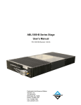
Operating Specifications
AirLift 115 Series Stage User's Manual
3.4. Limit Switches
AirLift 115 series stages are provided with end of travel limit switches. The limit switches signal when the
stage has reached its maximum useable travel distance in either direction.
3.4.1. Limit Switch Operation
Limit switches are integral to the stage's linear encoder. They are placed directly on the encoder scale at the
extents of nominal stage travel. When the stage encoder senses a limit, a clockwise (CW) or counterclockwise (CCW) limit signal is generated.
If the stage is driven past the electrical limit, it will encounter the hard stop. The stage's
shocks are designed to the stage's specifications. Damage to the stage could result from a
hard stop strike if the stage is driven at conditions exceeding its maximum velocity, acceleration, or payload specifications.
3.4.2. Limit Switch Wiring
Limit switches are open-collector, TTL–compatible devices powered by 5 Volts that change output states
when the stage approaches its maximum travel distance. Since they are open-collector devices, they may
be interfaced to 24 Volt logic inputs.
With the NC limit configuration, the input to the controller is seen as a logic 0 (typical 0.4V @ 12.8mA) when
no limit condition is present. When the limit switch is activated, a 5V source through a pull-up resistor, on the
controller, causes a logic 1 (typically 4.8-5V) to be seen by the controller input. See Figure 3-1 for a diagram
of limit switch wiring.
Figure 3-1:
16
Limit Switch Wiring
Chapter 3
www.aerotech.com