1
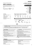
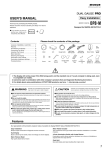
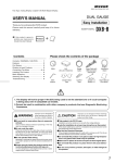
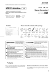
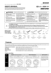
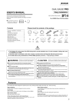
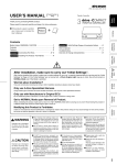
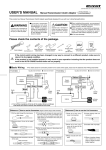
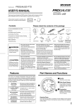
(52X-BM As of December, 2014 No.1)
USER’ S MANUAL
Triple Gauge Set for BMW
52X-BM
Thank you for purchasing this PIVOT product.
Please read this manual carefully and keep it for future reference.
● If this produc t is given to
another user, make sure to
include this User’ s Manual.
Product
+
Please check the contents of the package
Contents
Voltage
Meter
Contents / WARNING / CAUTION …… 1
Features ………………………………… 1
Part Names and Displays ……………… 1
Connecting The Wires and
Installing The Product …………… 2 ~3
Basic Operation ………………………… 4
Switching The Display ………………… 4
Troubleshooting ………………………… 4
Water Temp
Meter
Boost
Meter
Gauge Cable
×3
Peak Switch
Unit
Cut
Connectors
OBD Cable
with fuse 3A
Double-sided
Tape
(round) (square)
Cushion
Tape
×6
Fuse Power Cable
with fuse 3A
Zip Ties
(Large) × 2
(Small) × 5
User’ s
Manual
●You need the 3DDesign corporation brand Gauge Panel to install.(included in the full kit)
1. The display will not be proper if the ECU being used is not the standard one or if a sub-computer is being used, even in compatible car
models.
2. Cannot be used in combination with other company’ s products that use Diagnostic Monitoring Connectors.
3. For details about using in combination with other PIVOT products that use Diagnostic Monitoring Connectors please see our Web Site
at h t t p://p ivo t j p.c o m /o b d - e /.
4. On account of the mounting location, original cigar lighter and ashtray you will not be able to use.
WARNING
Improper use or disregard of these warnings
may result in the injury or death of people.
CAUTION
●Do not operate while driving.
●Do not work in areas where
there is excessive exhaust.
●This product is for DC12V cars;
Operating or checking the display
during driving may cause an
accident; please use with the utmost
consideration for safety.
Due to vehicle exhaust emission
poisoning or fire may result in a
damage to humans.
Installation cannot be carried out on cars
with other voltage batteries.
●Just after installation do not exert
any strong force on the product.
●Please securely fasten the
product to a stable place and
be sure to store bundle away
all wires with tape, etc...
●Do not crush the cable.
Please be careful that the cable
does not get crushed by the seat
rail or car door steel plate, nor cut
by any sharp steel plate as this
may cause a poor connection or
an electric short leading to fire or
other danger.
Improper use or disregard of these warnings may cause
injury to persons, damage the product and other things.
When double-sided tape is used for an
installation be warned that when hot the
tape temporarily losses adhesiveness.
●Do Not Use Chemical Cleansers.
It is very dangerous to pull tangled
wires by force or allow tangled wires
to interfere with driving.
If the unit gets dirty please wipe with a soft
c l o t h t o r e m ove a ny d i r t . D o n o t u s e
c h e m i c a l c l e a n s e r s s u c h a s t h i n n e r,
benzene, or alcohol.
●Do not install the product in any
place subject to high temperature
or any place where water may be
splashed.
●Make sure to replace all screws
and parts to their original place.
●Do not install the product in a
place where it will cause distraction.
●Do not, in any manner, process,
take apart, or make changes to
this product.
Features
Triple Gauge
Peak Switch
LED Illumination
No Piping or Wiring Necessary
Stepping Motor Drive
Simultaneous display of three types of data: Boost, Water Temperature and Voltage.
Boost and Water temp gauge can display the maximum value and Voltage gauge can display the lowest value.
Standard Matching Orange Illumination.(keep lighting the meter in operation)
It is possible to connect directly to the diagnostic monitoring connector meaning there is no need for troublesome wiring.
Our stepping motor is able to provide a smooth, highly precise display.
Part Names
Displays and Uses
Voltage
Display 7V〜17V
Check battery
Use
Water Temp
Boost
20˚C〜120˚C
0 ∼154kPa
Prevention of overheating
Check Heating etc.
Check Boost etc.
【Meter】
Bezel
Dial
120
20
1
40
Ex:14V
Ex:95˚C
Unit
(View from Gauge Connection)
TEMP °C
Ex:40kPa
Opening Demo
The needle will move to the lowest value side several times, then it will move to
the maximum value and finally to reading for current measurement item.
ø52
ø56.5
Shows
the current
values.
【Unit】
WATER
STEPPING
GAUGE
Meter
6 38
100
60
[Unit:mm]
(Absolute pressure display)
Needle
80
Size
70
Peak Switch
connector
50
Connect Peak Switch
1
2
2
Meter connector
Connect gauge cable
(View from Car Connection)
3
Depth 22
Power connector
Connect OBD Cable
3
1
Connecting the Wires and Installing the Product
Basic Wiring
Please carry out wiring with the engine turned OFF and the key removed.
Connect to Power
(1.5m)
IGN = 12V with
key switch ON
※Not as normal
power source
Peak Switch
Backside
of Meter
Backside
of Meter
2-pin
Connector
SW
Gauge Cable (1.5m)
METER
3-pin
Connector
3-pin
Connector
T h e 3 - p i n c o n n e c to r s
can be connected to any
of the three positions
1
Connecting to Power
1-pin
Connector
Unit
6-pin
Connector
Yellow
OBD
Backside
of Meter
※1
OBD Cable
Yellow
(2.7m)
Fuse Power Cable
with fuse 3A
Red
Red
Diagnostic
Monitoring
Connector
(0.5m)
※1
Do not use the Red Cable of 1-pin
connector from OBD Cable fuse.
OBD
Connector
(In case of right-hand drive)
In case of 1 and 3 series
① Remove the under cover of the passenger side glove box.
② Open the bonnet and check the position of the fuse box.
③ Remove the cover
above the fuse box.
⑤ Pr y o p e n t h e f u s e
case using such as
drivers.
⑥ Pass the Fuse
Power Cable
through the hole in
the fuse case back
and pull it to car
interior and connect
the 1-pin Connector.
④ Remove the fuse box
cover.
⑦ Replace the original fuse 5A of the sixth position
from the left to the fuse of the Fuse Power Cable.
⑧ Routed the Fuse Power Cable as shown in the figure.
⑨ Return in the reverse order.
2
In case of Z4
① Rem ove t he un d er
cover of the passenger side glove box.
(3 places screw)
③ Connect the cable of
2-pin connector(the
position of the figure)
on back of the cigar
lighter socket to the
tip of the Fuse Power
Cable using Cut
Connector.
Cigar lighter
② Cut the fuse of Fuse
Power Cable as
shown in the diagram.
Fuse Power Cable with fuse 3A
Connect
Yellow
Fuse
Cut
Fuse
④ Put back the under cover.
【Reference 1】How to use the Cut Connectors
1
2
10 mm
Peel off of the vinyl
cover at connection.
2
3
10 mm
Peel off of the vinyl
cover at the end of
the product’ s wire.
4
Wrap around
both wire coils.
5
C l o s e t i g ht l y w i t h
cut connector.
Insulate with vinyl
tape.
When crimping, please
use crimpers or use
pliers to bend and then
solder together.
Connecting each Cable and the Unit
① Laying the Gauge Cable from the mounting position of the Meter to the Unit. 【Reference 2】Notes about using the OBD Connector
② Connect 1-pin connector of the Fuse Power Cable to the 1-pin connector of
OBD Cable.
Make sure to grip the
distended portions when
pulling it out or inserting it.
CAUTION
Do not pull on the wires
when trying to remove the
connector; the wires may
become disconnected.
③ Connect the Peak Switch, the Gauge Cable and the OBD Cable to the Unit.
④ Insert the OBD Connector to the diagnostic monitoring connector. (Remove
the cover of the diagnostic monitoring connector if it's annoying.)
If you unable to get a grip
on the distended portions.
W i t h s o m e c ar m o d e l s i t
m ay b e d i f f i c u l t t o g e t a
good grip on the connector.
3
Installing The Product
Installing the Meter
For procedure of the installation of the meter
panel, please refer to the instruction manual
of the meter panel (3DDesign Corporation).
① Affix cushion tapes(included) to the Meter.
② Connect the Meter and Gauge Cable, and press
into the meter panel.
Cushion Tape
(two to four places)
Installing the Unit
Installing the Peak Switch
Fasten the unit into positions not usually affected by
water.
Fasten the switch to a position
that is easy to operate.
Fastening to
Flat Space
When Fastenings
to a Cable or Pipe
Double-sided
tape(square)
(Included)
Through
holes
Thick cable
or pipe
Placement
Installation direction
Basic place would be in the figure, but arrangement on
your preference is also possible.
※Meter can be connected to any of the 3-pin connector.
Can be adjusted to the easy-to-read and preference
direction.
Water Temp
Fastening to
Flat Space
Peak Switch
Zip tie
(Large)
Unit
Clean to
remove
oil and dust.
Voltage
In such case, pull
out the connector
by pulling on the
end of the zip tie.
Double-sided
tape(round)
(Included)
Clean to
remove
oil and dust.
Boost
3
Basic Operation
1
Key Switch ON
2
(Engine start)
Opening Demo
(Start-up all together)
3
4
Real-time display
(Engine stop)
5
Meter OFF
START
STOP
START
STOP
EN
Key Switch OFF
EN
GINE
GINE
STOP
START
Switching The Display
Peak reading display
1
Reset the Peak reading
1
Press the switch
once
While the meter is in operation, press
the switch once.
2
Product
Pressing the switch while displaying the peak
reading will reset the peak reading.
Peak reading display
2
3
Real-time display
Reset the Peak reading
Peak
VOLTAGE
Lowest side
WATER TEMP
Maximum side
BOOST
Maximum side
Reset all three meters at the same time.
Display all three meters at the same time.
3
Press the switch
for 3 seconds
Real-time display
Back to real-time display after 3 seconds releasing
the switch.
※Each peak value can be reset by the key OFF.
Measuring the lowest voltage by voltmeter
1
START
STOP
EN
START
STOP
or
EN
GINE
Without braking,
press down twice
(1, 3 series)
GINE
Turn the key switch ON
and display the meter
2
Without braking,
insert the key and
press down once
(Z4)
START
STOP
EN
GINE
Start the engine and
check the lowest voltage
with Peak reading display
With braking,
press down once
●Recommend to charge or replace the battery if it's lower about 1V or more than when new.
Troubleshooting
Trouble
Possible Causes
Possible Solutions
Poor connection of OBD Connector and
Fuse Power Cable .
Please reconfirm whether wiring and connections of
OBD Connector and Fuse Power Cable are correct or not.
Poor connection or wrong wiring of Yellow cable
if wired directly to the power supply.
Please reconfirm whether wiring and connections of Yellow
cable is correct or not.
The unit has been installed into an incompatible
car model.
Please check the “Fitting List” .
One or two meters do not work.
Poor connection of Gauge Cable .
Please reconfirm whether wiring and connections of
Gauge Cable is correct or not.
Needle of the boost gauge is shifted
to slightly negative from 0 than the
others(relative pressure).
Depending on the altitude, needle shifts about one scale by the characteristics of car side sensor
(absolute pressure), but this is not a malfunction.
All three meters do not work.
※Our products have already been recognized as our Industrial Property or are in the process of receiving Industrial Property status.
※We plan in the near future to take all possible legal measures to protect against unfair competition from look-alike products using similar designs, regulating characteristics,
circuitry and circuitry layout.
※We strictly prohibit the unlicensed use of the PIVOT trademark and the unauthorized use of PIVOT User’ s Manual.
4
PIVOT CORPORATION 87-3, Shimookada Okada, Matsumoto-shi, Nagano, 390-0313 JAPAN
http://pivotjp.com/