1
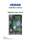
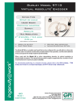
ISC3N
ENCODER INTERFACE WITH DIGITAL I/O
PCI Version
USER’S MANUAL
Gurley Precision Instruments
INTRODUCTION
The ISC3N card is a PCI bus compatible Encoder Interface with Digital Inputs and
Outputs that provides a direct transfer of position values from incremental encoders
to the PC without any external position readout units. The additional digital
input/output lines make the ISC3N card ideal for use in motion control systems,
measurement applications, position regulations, etc. It is possible to connect up to
three incremental encoders, and 16 digital inputs and outputs to the PC with a single
ISC3N card.
FEATURES
•
•
•
•
•
•
•
•
•
•
Counting in positive and negative direction
Trigger initiated counting
Trigger latched counting
Position latched counting
Reset/Preset
Counting error detection (phase error)
16 programmable I/O lines divided in four groups
3 output lines may be programmed to output equality status bits
3 inputs as External triggers or additional inputs
Interrupt request may be generated by Trigger, Error Detection or Position
Equality
• Fast industry standard PCI interface
ISC3N CHARACTERISTICS
• Three 32-bit counters
• Input signals from incremental encoders:
1. A, B, RI +5V TTL compatible
2. A+, A-, B+, B-, RI+, RIRS422 compatible
• Digital input filters
2 stages
• Input pulse width, low or high - tW
60 ns min. (see figure below)
• Phase difference between any A and B
signal transitions - tAB 30 ns min. (see figure below)
• Digital Inputs and Outputs
+5V TTL compatible, buffered,
47kΩ pull-ups
• Output current 25 mA max.
• Power consumption
200 mA max.
• IRQ line INTA#
• PCI 5V, 32-bit, 33MHz compatible, PCI 3.3V optional
ISC3N - PCI
1
Gurley Precision Instruments
tW
tW
A
t AB
B
Figure 1: Encoder input signal requirements
DESCRIPTION
Each encoder input channel of the ISC3N consists of a line receiver, quadrature
decoder with phase error detection, control logic for trigger evaluation, 32-bit counter,
32-bit latch, 32-bit register and 32-bit equality comparator. It is possible to reset and
preset the counter. The data from the counter is accessed only through the latch.
The ISC3N can be programmed to operate in several different modes:
- counter counts independently of any trigger signals,
- counter starts counting when the trigger signal is detected,
- latch follows the counter, that is, the latch is transparent,
- counter data is latched whenever the trigger signal is detected,
- all counters are latched whenever selected counter data equals to register data
(latching at desired position).
INSTALLATION
Power off your PC and insert the ISC3N card in a free PCI expansion slot. Upon
power-up the operating system should detect the card. Then simply follow the Driver
Installation Wizard.
ISC3N - PCI
2
Gurley Precision Instruments
BLOCK DIAGRAM
K2
Data Transceivers
IOCP: I/O Control Port
IOB15..0
EXTi
IOP: 16-bit I/O Port
DOCP: Digital Output
Control Port
Z
ESDIP: Error Status and
Digital Input Port
Y
X
DB9X
Encoder
Input X
MCP: Mode Control Port
Equality Comparator
TSIEP: Trigger Status and
Interrupt Enable Port
Register
Digital Input Filter
Counter
Quadrature Decoder
Latch
SP: Status Port
DB9Y
Encoder
Input Y
DB9Z
Encoder
Input Z
CP: Control Port
Trigger Control Logic
PCI Target Interface
PCI bus
ISC3N - PCI
3
Gurley Precision Instruments
CONNECTOR PIN ASSIGNMENT
- DB9X, Y, Z Encoder Connectors, Sub-D DB9 female
+5V TTL
GND
RI
B
A
+5V
RS422
GND
RI+
B+
A+
+5V
Pin No.:
1
6
2
7
3
8
4
9
5
RS422
RI–
B–
A–
GND
+5V TTL
GND
- K2 I/O Connector, HD26 male or Sub-D DB25 female
HD26
GND
EXTX–
EXTY–
EXTZ–
GND
IOB1
IOB3
IOB5
IOB7
IOB9
IOB11
IOB13
IOB15
Pin No.:
1
2
3
4
5
6
7
8
9
10
11
12
13
14
15
16
17
18
19
20
21
22
23
24
25
26
HD26
EXTX+
EXTY+
EXTZ+
+5V
IOB0
IOB2
IOB4
IOB6
IOB8
IOB10
IOB12
IOB14
GND
DB25
GND
EXTX–
EXTY–
EXTZ–
GND
IOB1
IOB3
IOB5
IOB7
IOB9
IOB11
IOB13
IOB15
Pin No.:
1
14
2
15
3
16
4
17
5
18
6
19
7
20
8
21
9
22
10
23
11
24
12
25
13
DB25
EXTX+
EXTY+
EXTZ+
+5V
IOB0
IOB2
IOB4
IOB6
IOB8
IOB10
IOB12
IOB14
The EXTi inputs are normally used as external triggers, but may also be used as
additional general-purpose digital inputs.
The IOB0..15 pins are programmable I/O lines divided in four groups by four. Each
group may be programmed to function as inputs or as outputs.
The pins IOB0..2 may be individually programmed to output the Count=Register
(C=Ri) equality status of the channels X, Y and Z, respectively.
Total loading of the +5V pins should be kept below 200mA. A short-circuit from these
pins to any other pin must be avoided.
Connectors K3 and K4 are reserved for factory test.
ISC3N - PCI
4
Gurley Precision Instruments
ISC3N Registers
BAR
+00
+04
+08
+0C
+10
+14
+18
+1C
+20
+24
+3
+2
+1
+0
XCNT - X Counter
XREG - X Register
YCNT - Y Counter
YREG - Y Register
ZCNT - Z Counter
ZREG - Z Register
IOP
SP
MCP
IOCP
CP
ESDIP
TSIEP
DOCP
XCNT, YCNT, ZCNT – X, Y, Z Encoder Counters / offsets 00, 08, 10h
0
31
0
ICNT
XREG, YREG, ZREG – X, Y, Z Compare Registers / offsets 04, 0C, 14h
04
31
0
IREG
IOP – I/O Port / offset 18h
18
31
16 15
0
IOB[15:0]
IOCP – I/O Control Port / offset 1Ch
7
ISC3N - PCI
6
5
4
3
GDD3
5
2
GDD2
1
GDD1
0
GDD0
Gurley Precision Instruments
GDDi
0
1
Group Data Direction
Inputs
Outputs
Bit GDD0 controls IOB[3:0], GDD1 controls IOB[7:4], GDD2 controls IOB[11:8] ,
GDD3 controls IOB[15:12].
CP - Control Port / offset 20h
7
6
5
CI
4
DL
3
2
CI
0
1
Count Inhibit
Counters enabled
Counters stopped
DL
0
1
Counter Read Latch Control
Counter data is latched
Read Latch is transparent and follows counter
data
1
0
TSIEP - Trigger Select and Interrupt Enable Port / offset 21h
7
TSi
0
1
ERIE
0
1
6
ERIE
5
EQIE
4
TRIE
3
2
TSZ
Trigger Source
Reference Impulse (RIi)
External Trigger (INi)
Error Interrupt Enable
Error interrupt disabled
Enable interrupt on quadrature decoder error
(ERRi)
ISC3N - PCI
6
1
TSY
0
TSX
Gurley Precision Instruments
EQIE
0
1
Equality Interrupt Enable
Equality interrupt disabled
Enable interrupt on equality (C=Ri)
TRIE
0
1
Trigger Interrupt Enable
Trigger interrupt disabled
Enable trigger interrupt (Ti)
MCP - Mode Control Port / offset 22h
7
6
iM1
0
0
1
1
iM0
0
1
0
1
5
ZM1
4
ZM0
3
YM1
2
YM0
1
XM1
0
XM0
Counter Mode
Continuous counting mode
Latch counter data on trigger (Ti)
Start counter after trigger (Ti)
Latch all counters on equality (C=Ri)
The iM1 M0 bits control the count enable (iM0) and latch function (iM1) of the
selected channel, except when iM0 M1=11, they also affect other two counters.
SP - Status Port / offset 23h
7
Ti
C=Ri
6
T
Z
5
T
Y
4
T
X
3
2
C=R
Z
1
C=R
Y
0
C=R
X
Logic High indicates that the corresponding trigger signal has been detected.
Bits are cleared by writing zeros to them.
Logic High indicates that the counter data equalled the corresponding
register. Bits are cleared by writing zeros to them.
ISC3N - PCI
7
Gurley Precision Instruments
ESDIP - Error Status and Digital Input Port / offset 24h
7
ERRi
INi
6
ERRZ
5
ERRY
4
ERRX
3
2
INZ
1
INY
0
INX
Logic High indicates that the built-in quadrature decoder detected an invalid
transition of the encoder AB input signals. Bits are cleared by writing zeros to
them.
These bits are read-only and their values correspond to the logic level of the
respective K4 connector input pins EXTi.
DOCP - Digital Output Control Port / offset 25h
7
OCi
0
1
6
OCZ
5
OCY
4
OCX
3
2
1
0
Digital Output Control
Connector pins IOB[2:0] correspond to bits in I/O PORT
Connector pins IOB[2:0] correspond to C=RZ, C=RY,
C=RX status bits in SP, respectively.
This feature enables routing equality status to the outside world via IOB[2:0] port
signals.
ISC3N - PCI
8
Gurley Precision Instruments
SOFTWARE REFERENCE
EIPCI32.DLL functions description
The EIPCILibOpen opens and allocates the resources used by the driver. This
function must be matched with a call to EIPCILibClose.
Int EIPCILibOpen();
Parameters:
none
Result of
0: OK
2: Driver can not be opened.
NOTE:
The EIPCILibOpen function has to be called first to open the driver.
The EIPCILibClose closes and releases the resources used by the driver.
VOID EIPCILibClose();
Parameters:
none
NOTE:
This function must be matched with a call to EIPCILibOpen.
ISC3N - PCI
9
Gurley Precision Instruments
The ISC3N initalization routine. The EIPCIInit function:
Detects the installed card,
resets I/O Port and I/O Control Port,
resets Trigger Select and Interrupt Enable Port, resets Mode Control Port, resets
Status Port,
resets Error Status and Digital Input Port,
resets Digital Output Control Port,
resets X, Y and Z axis position.
int EIPCIInit ();
Parameters:
none
Result of
0: OK
1: Card not installed
2: Driver not opened.
NOTE:
The EIPCIInit function detects the card and initializes the cards parameters. It is
usually called immediatelly after the EIPCILibOpen call.
The ISC3N initalization routine. The EIPCIInitEx function:
Detects the installed card,
resets I/O Port and I/O Control Port,
resets Trigger Select and Interrupt Enable Port, resets Mode Control Port, resets
Status Port,
resets Error Status and Digital Input Port,
resets Digital Output Control Port.
int EIPCIInitEx ();
Parameters:
none
Result of
0: OK
1: Card not installed
2: Driver not opened.
NOTE:
The same as EIPCIInit except it doesn't reset the X, Y and Z counters.
ISC3N - PCI
10
Gurley Precision Instruments
The EIPCIReadAxis function returns the Counter Value (current position) of the
selected axis, accessed through the Latch as a signed 32 bit value.
int EIPCIReadAxis (
BYTE Axis,
BYTE DLMode
);
// Axis selected
// Data Latch mode
Parameters:
Axis
One of the three channels of the ISC3N Card selected
1 : X Axis
2 : Y Axis
3 : Z Axis
DLMode
DLMode defines the DL bit of the ISC3N Control Port while reading position
0 : DL bit of Control Port is set to 1 while reading position data from
the Latch. After reading the data the DL bit remains set to 1.
1 : DL bit of Control Port is set to 0 while reading position data from
the Latch. After reading the data the DL bit is set to 1.
2 : DL bit of Control Port is set to 0 while reading position data from
the Latch. After reading the data the DL bit remains set to 0.
The EIPCIPresetAxis function presets the Counter of the selected axis with signed
32 bit Value.
VOID EIPCIPresetAxis (
BYTE Axis,
int Value
);
// Axis selected
// Preset Value
Parameters:
Axis
One of the three channels of the ISC3N Card selected
1 : X Axis
2 : Y Axis
3 : Z Axis
Value
Preset Value
ISC3N - PCI
11
Gurley Precision Instruments
The EIPCIReadRegister function returns the axis Register Value as a signed 32 bit
value.
int EIPCIReadRegister (
BYTE Axis,
);
// Axis selected
Parameters:
Axis
One of the three channels of the ISC3N Card selected
1 : X Axis
2 : Y Axis
3 : Z Axis
The EIPCIPresetRegister function writes signed 32 bit Value to the axis Register.
Corresponding C=R bit of the Status Port is set when the Counter data equals the
Register data.
VOID EIPCIPresetRegister (
BYTE Axis,
// Axis selected
int Value
// Preset Value
);
Parameters:
Axis
One of the three channels of the ISC3N Card selected
1 : X Axis
2 : Y Axis
3 : Z Axis
Value
Preset Value
The EIPCIResetAxis function presets the axis Counter with value of 0.
VOID EIPCIResetAxis (
BYTE Axis
);
// Axis selected
Parameters:
Axis One of the three channels of the ISC3N Card selected
1 : X Axis
2 : Y Axis
3 : Z Axis
ISC3N - PCI
12
Gurley Precision Instruments
The EIPCISetCountingMode function sets the axis counting mode.
VOID EIPCISetCountingMode (
BYTE Axis,
// Axis selected
BYTE CountingMode
// Counting mode selected
);
Parameters:
Axis
One of the three channels of the ISC3N Card selected
1 : X Axis
2 : Y Axis
3 : Z Axis
CountingMode
CountingMode byte defines the counting mode of the selected axis
0 : Continuous Counting Mode
1 : Trigger Latched Counting Mode
2 : Trigger Started Counting Mode
3 : Equality Latched Counting Mode
The EIPCIGetEqualityStatus function returns C=R (D0-D2) bits of the Status Port.
BYTE EIPCIGetEqualityStatus ();
Parameters:
none
The EIPCIResetEqualityStatus function resets C=R (D0-D2) bits of the Status Port.
VOID EIPCIResetEqualityStatus ();
Parameters:
none
The EIPCIGetTriggerStatus function returns T (D4-D6) bits of the Status Port.
BYTE EIPCIGetTriggerStatus ();
Parameters:
none
ISC3N - PCI
13
Gurley Precision Instruments
The EIPCIResetTriggerStatus function resets T (D4-D6) bits of the Status Port.
VOID EIPCIResetTriggerStatus (
BYTE Axis
// Axis selected
);
Parameters:
Axis
One of the three channels of the ISC3N Card selected
1 : X Axis
2 : Y Axis
3 : Z Axis
The EIPCISetTriggerSource function selects Trigger Source.
VOID EIPCISetTriggerSource (
BYTE Axis,
// Axis selected
BOOL ExternalTrigger
// External trigger flag
);
Parameters:
Axis
One of the three channels of the ISC3N Card selected
1 : X Axis
2 : Y Axis
3 : Z Axis
ExternalTrigger
ExternalTrigger flag defines Trigger Source of the selected axis
FALSE : the Reference Impulse as Trigger Source
TRUE : the External Trigger as Trigger Source
The EIPCIGetErrorStatus function returns ERR (D4-D6) bits of the Error Status and
Digital Input Port.
BYTE EIPCIGetErrorStatus ();
Parameters:
none
ISC3N - PCI
14
Gurley Precision Instruments
The EIPCIResetErrorStatus function resets ERR (D4-D6) bits of the Error Status
and Digital Input Port.
VOID EIPCIResetErrorStatus ();
Parameters:
none
The EIPCISetIOP function writes the 16 bit Value to the I/O Port.
VOID EIPCISetIOP (
WORD Value
);
// Value
Parameters:
Value
Byte value, written to the I/O Port
The EIPCISetIOCP function writes the Value to the I/O Control Port.
VOID EIPCISetIOCP (
BYTE Value
);
// Value
Parameters:
Value
Byte value, written to the I/O Control Port
The EIPCISetCP function writes the Value to the Control Port.
VOID EIPCISetCP (
BYTE Value
);
// Value
Parameters:
Value
Byte value, written to the Control Port
ISC3N - PCI
15
Gurley Precision Instruments
The EIPCISetTSIEP function writes the Value to the Trigger Select and Interrupt
Enable Port.
VOID EIPCISetTSIEP (
BYTE Value
);
// Value
Parameters:
Value
Byte value, written to the Trigger Select and Interrupt Enable Port
The EIPCISetMCP function writes the Value to the Mode Control Port.
VOID EIPCISetMCP (
BYTE Value
);
// Value
Parameters:
Value
Byte value, written to the Mode Control Port
The EIPCISetSP function writes the Value to the Status Port.
VOID EIPCISetSP (
BYTE Value
);
// Value
Parameters:
Value
Byte value, written to the Status Port
The EIPCISetESDIP function writes the Value to the Error Status and Digital Input
Port.
VOID EIPCISetESDIP (
BYTE Value
);
// Value
Parameters:
Value
Byte value, written to the Error Status and Digital Input Port.
Note:
Bits D0 to D3 of the ESDIP are read-only.
ISC3N - PCI
16
Gurley Precision Instruments
The EIPCISetDOCP function writes the Value to the Digital Output Control Port.
VOID EIPCISetDOCP (
BYTE Value
);
// Value
Parameters:
Value
Byte value, written to the Status Port
The EIPCIGetIOP function returns D0-D15 bits of the I/O Port.
WORD EIPCIGetIOP ();
Parameters: none
The EIPCIGetIOCP function returns D0-D7 bits of the I/O Control Port.
BYTE EIPCIGetIOCP ();
Parameters:
none
The EIPCIGetCP function returns D0-D7 bits of the Control Port.
BYTE EIPCIGetCP ();
Parameters:
none
The EIPCIGetTSIEP function returns D0-D7 bits of the Trigger Select and Interrupt
Enable Port.
BYTE EIPCIGetTSIEP ();
Parameters:
none
ISC3N - PCI
17
Gurley Precision Instruments
The EIPCIGetMCP function returns D0-D7 bits of the Mode Control Port.
BYTE EIPCIGetMCP ();
Parameters:
none
The EIPCIGetSP function returns D0-D7 bits of the Status Port.
BYTE EIPCIGetSP ();
Parameters:
none
The EIPCIGetESDIP function returns D0-D7 bits of the Error Status and Digital
Input Port.
BYTE EIPCIGetESDIP ();
Parameters:
none
The EIPCIGetDOCP function returns D0-D7 bits of the Digital Output Control Port.
BYTE EIPCIGetDOCP ();
Parameters:
none
ISC3N - PCI
18