1
Design and Implementation of a Remotely Controlled
Electronic Door Lock
By
Rabab Osman Mohammed Said Farh
B.Sc. (HONOUR) in Telecommunication,
University of Gezira, 2003
A Thesis Submitted to the University of Khartoum as a
Partial Fulfillment of the Requirements for the degree of
M.Sc. in Computer Architecture and Networking
Supervisor:
Professor: Sharief F. Babikir
Department of Electrical and Electronic Engineering
Faculty of Engineering
January 2015
ق ال هللا تعالى:
ِب ِبي ِهَّللِب
للِب ِبي
لل ْس َم ِب ِهَّلل
ا ِهَّلل
ْس
﴿وَشي انزَن أوتىا انعهى انزٌ
أنزل إنُك ين سبك هى انحك وَهذي
إنٍ صشاط انعزَز انحًُذ﴾
صذق هللا انعظُى
سىسة سبأ اَِت ()5
I
Dedication
To my sister Rihab Osman who supported to do my best in
life, study, work …
Acknowledgement
II
Thanks first and last to ALLAAH who enabled me to conduct this
study by grace of him and gave me strength. For all those who stood by
me, and helped me in this thesis, I send my thanks and deepest gratitude.
Special and deepest regards to my supervisor Prof. Sharief Fadul Babiker
for his continuous supports, help and patience.
Last but not least, special thanks are to my friends who have shared their
opinions and useful information as well as the technical support to me
in order to complete the project.
Abstract
This thesis describes the design and implementation of a Microcontroller
based security system. It provides users with an efficient and reliable
security system that supports the use of an electronic keypad or mobile
phone, Dual Tone Multiple Frequency (DTMF) arranged to send signals
to the control unit. The system provides the ability to authenticate the
user and to on lock the entry point.
The system was implemented using a microcontroller interfaced to a
DTMF decoder together with a stepper motor. The system has been
successfully tested under normal operating conditions and this system
was found to provide the expected functionality.
المستخلص
هزا انبحث َصف تصًُى وتهُئت نظبو حًبَت َعتًذ عهً انًتحكى انذلُك
وَزود انًستخذو بنطبو رو كفبء وفبعهُت وهزا اننظبو َستخذو فُه نىحت انًفبتُح
اوانهبتف انجىال ،تشدد انننً ِةت انلنباُ ِةت انًتعذّ ِةد (دٌ .تً .أو .اف) إلسسبل إشبسة
نىحذة انتحكى .واننظبو َزود انًستخذو بًمذسة عهً انتحكى فً نمبط انىصىل.
هزا اننظبو تى تهُئت بئستخذاو انًتحكى انذلُك بتىصُههب يع (دٌ .تً .أو
.اف) وتىصُههًب ببنًىتىس .تى إختببس وتشنُم هزا اننظبو عهً انطبُعت حُث انه
َؤدي انًهبو وانىظباف انًطهىبت ين تصًًُه.
Table of Contents
Title
Chapter One: Introduction
Background
1.1 Problem Definition ………………………………………………….
1.2 Objectives ……………………………………………………………
1.3 Methodology…………………………………………………………
1.4 Thesis Layout…………………………………………………………
Page No.
1
1
2
2
2
Chapter Two: Literature Review
Introduction
2.1 Biometric System……………………………………………………..
2.2 Similar Study …………………………………………………………
2.3 PIC Microcontroller………………………………………………….
4
5
8
9
Chapter Three: System Design
Introduction
3.1 System flow chart…………………………………………………….
3.2 Introduction to Proteus Software…………………………………….
3.3 MikroC PRO for PIC………………………………………………….
3.4 System Circuit Diagram………………………………………………
3.5 PIC K150 programmer………………………………………………..
3.6 Dual Tone Multiple Frequency (DTMF) …………………………….
3.7 Stepper Motor…………………………………………………………
3.8 Keypad Interface with Microcontroller………………………….……
3.9 Interfacing LCD with Microcontroller ……………………….……….
10
11
12
13
14
16
17
20
22
23
Chapter Four: Result and discussions
4.1 Simulation Results and discussions ………………………………….
4.2 Results of hardware construction……………………………………
24
29
Chapter Five: Conclusion and Recommendation
5.1 Conclusions…………………………………………………………… 34
5.2 Recommendations…………………………………………………… 34
References……………………………………………………………….. 36
Appendices
Appendix A (Project code)
Appendix B (PIC 16F877A Data Sheet)
Appendix C (ULN2803)
Appendix D (MT8870)
List of Figures
Figure Name
Page No.
Figure (3.1) - Block diagram the door lock………………………….….
Figure (3.2) - System Flow Chart……………………………………….
Figure (3.3) - Proteus simulation program……………………………..
VI
Figure (3.4) - MikroC program for PIC……………………………........
Figure (3.5) - Circuit diagram of the door lock controller………………
Figure (3.6) - PIC k150 programmer………………………………........
Figure (3.7) - Functional Block Diagram of MT8870………………….
Figure (3.8) - MT8870 Single-Ended Input Configuration………..........
Figure (3.9) - Stepper motor…………………………………………….
Figure (3.10) - ULN 2803 interface to stepper motor…………………..
Figure (3.11) - Keypad 4*4…………………………………………......
Figure (3.12) - LCD 16*2 Pin Diagram…………………………………
10
11
12
13
15
16
17
18
20
21
22
23
Figure of Result in Simulation program
Figure (4.1) - System design in proteus program……………………
Figure (4.2) - Initial state of system …………………………………
Figure (4.3) - system waiting password from keypad………………
Figure (4.4) - Entering password to system from keypad………….
Figure (4.5) - Motor is activated in order to unlock the door………
Figure (4.6) - Motor is activated in order to lock the door ………...
Figure (4.7) - system waiting password from Mobile………………
Figure (4.8) - system message when entered password is wrong. ...
Figure of Results of hardware construction
Figure (4.9) - System hardware design………………………………
Figure (4.10) - Initial state of system………………………………..
Figure (4.11) - system waiting password from keypad…………….
Figure (4.12) - Entering password to system from keypad………...
Figure (4.13) - Motor is activated in order to unlock the door……..
Figure (4.14) - Motor is activated in order to lock the door………..
Figure (4.15) - system waiting password from Mobile……………..
Figure (4.16) - system message when entered password is wrong...
Figure (4.17) - Overall system and desired output………………….
24
24
25
25
26
26
27
28
29
29
30
30
31
31
32
33
33
List of Tables
Table Name
Pages No.
Table (3.1) - DTMF keypad frequenciesVII
…………………………..
Table (3.2) - Digit coding…………………………………………...
Table (3.3) - Four different steps of stepper motor………………
Table (3.4) - Connect keypad in PORTD………………………….
Table (3.6) - LCD 16*2 Pin Description…………………………..
19
19
21
22
23
List of Abbreviations
ANSI
CISC
CPU
DTMF
EMF
I/O
IDE
LCD
LD
OACS
PIC
RISC
American National Standards Institute
Complex Instruction Set Computing
Central ProcessingVIII
Unit
Dual-Tone Multiple Frequency
Electromotive Force
Input/ Output
Integrated Development Environment
Liquid Crystal Display
Loop disconnect
Office Access Control System
Programmable Interface Controller
Reduced Instruction Set Computing
Chapter One
Introduction
Chapter One
Introduction
Background
Efficient and reliable security systems are needed for most
access point. Traditional keys may be forgotten anywhere, also remote
access control may be needed for those who are far away and while
someone should access the point without been informed of the required
access password.
1.1.
Problem Definition
Devices such as motion detectors, light detectors among others are
susceptible to be triggered by false signals such as noise impulses,
whenever its sensitivity is increased. They are not suitable for most
outdoor security protection due to the fact that they don‟t possess high
discriminative capability during operation and they are fairly expensive.
It is hence imperative to provide a locking device, one which is
suitable for outdoor security protection also efficient, reliable and low
cost. It includes using correct personal identification numbers to operate
the locking device.
The automatic lock finds application in homes, banks in the field of
military applications i.e. ammunition ware house and industries etc.
1.2. Objectives
To design and build a low-cost, keyless security system using
1 mobile phone (DTMF) if it is
keypad build in the access point or
required to open the door for kids or relatives when the user or owner
is far away from the access point .
1.3. Methodology
In this project Proteus simulation program will be used to design
the electronic circuit with microcontroller as the main control unit, C
code will be written using MikroC Compiler, the code will be burned
to PIC16F877A using PIC k150 programmer, the circuit will be
designed, analyzed and tested. The modules considered in this project
are (The keypad unit, Mobile phone (DTMF) unit, display unit, output
motor (ULN2803+ MOTOR) unit.
1.4. Thesis Layout
Chapter two (Literature Review) gives an introduction to door
lock
system,
Biometric
System,
Similar
Study
and
PIC
Microcontroller.
Chapter three (system design) this chapter discusses proteus
simulation program, mikroC compiler, PIC k150 programmer and
circuit of the project. This chapter discusses all software and hardware
that used to build door lock system.
Chapter four (Result): this chapter discusses results of the
project started with results of simulation in proteus program and results
of hardware construction.
Chapter five (conclusion and Recommendations): this chapter
contains the conclusion that can be drawn from this thesis, based on the
work
introduced
by
chapter
four.
Also
contains
recommendation to develop this system in the future.
2
some
of
Chapter Two
Literature Review
Chapter Two
Literature Review
Access control security systems are used as selective systems to
decide who can access a given location based on a personal distinctive
trait of the user. From the past time to the present, security locks
usually include mechanical devices made of forged metal, door chain,
pin tumbler lock, jam lock and padlock etc.
Other recently developed security devices are gadgets like laser
beam detectors, motion detectors and magnetic card readers. Most
recent of these devices are offshoots of biometric engineering. They
include voice recognition systems, finger print readers, retina eye
scanners …etc.
The major characteristic of security devices is to prevent an
intruder from gaining access to a location. Most of these devices,
however, have lapses and loophole which may give an unauthorized
person access to location where they are barred.
The simple jam lock and pad lock can be forced open or the keys
duplicated by unauthorized persons and under certain conditions,
physical changes of the individual concerned, the biometric devices
sometimes fail in recognizing the authentic individual concerned.
Hence they cannot be totally relied on. Furthermore, these
devices are very expensive, their use is restricted only to few
individuals or organizations that can afford it.
2.1
Biometric System
Biometrics is defined as the unique (personal) physical/logical
characteristics or traits of human body. These characteristics and traits
are used to identify each human. Any details of the human body which
differs from one human to other will be used as unique biometric data
to serve as that person's unique identification (ID), such as: retinal, iris,
fingerprint, palm print and DNA. Biometric systems will collect and
store this data in order to use it for verifying personal identity. The
combination of biometric data systems and biometrics recognition/
identification technologies creates the biometric security systems [1].
2.1.1 Facial Recognition Detector
The human face is one of the characteristic which can be used in
biometric security system to identify a user. Face recognition
technology, is very popular and is used more widely because it does
not require any kind of physical contact between the users and device.
Cameras scan the user face and match it to a database for verification.
Furthermore, it is easy to install and does not require any expensive
hardware. Facial recognition technology is used widely in a variety of
security systems such as physical access control or computer user
accounts. However, it is still not as unique as its counterparts such as
retinal, iris or DNA. Therefore, it is normally used with other
characteristics in the system. On the other hand, time is the most
negative affective factor with face recognition technology because as
the user ages will change over time [1].
5
2.1.2 Fingerprint Reader
Our fingerprint is made of a number of ridges and valley on the
surface of finger that are unique to each human. "Ridges are the upper
skin layer segments of the finger ".
There are several benefits of using fingerprint recognition
systems. This system is easy to use and install. Equipment has low
power consumption. However, there are some disadvantages in this
system. If the surface of the finger gets damaged and/or has one or
more marks on it, identification becomes increasingly hard.
Furthermore, the system requires the users' finger surface to have a
point of minutiae or pattern in order to have matching images. This
will be a limitation factor for the security of the algorithm [1].
2.1.3 Voice Recognition
There are two main factors which makes a person's voice unique.
Firstly, it is the physiological component which is known as the voice
tract. Secondly, it is a behavioral component which is known as the
voice accent. By combining both of these factors, it is almost
impossible to imitate another person's voice exactly and unauthorized
users can record authorized users' voices and run it through the
verification process in order to get user access control to system [1].
2.1.4 Iris Scanner & Recognition
The human iris is a thin circular structure in the eyes which is
responsible for controlling the diameter and size of the pupils. It also
controls the amount of light which is allowed through to retinal in
order to protect the eye's retina. Iris color is also a variable different to
each person depending upon their genes. Iris color will decide eye
color for each individual. Iris recognition systems will scan the iris in
6
different ways. It will analyze over 200 points of the iris including:
rings, furrows, freckles, the corona and others characteristics. After
recording data from each individual, it will save the information in a
database for future use in comparing it every time a user want to access
to the system [1].
2.1.5 Veins Recognition
One of the recent biometric technologies invented is the vein
recognition system. Veins are blood vessels that carry blood to the
heart. Each person's veins have unique physical and behavioral traits.
Taking advantage of this, biometrics uses unique characteristics of the
veins as a method to identify the user. Vein recognition systems mainly
focus on the veins in the users hands. Each finger on human hand has
veins which connect directly with the heart and it has its own physical
traits [1].
2.1.6 DNA Biometrics System
One of biometrics technology which is used in security systems
recently is DNA biometrics. It is impossible to fake this characteristic
because each person's DNA is unique. Each person's DNA contains
some trait from his/her parents. Each cell in the human body contains a
copy of this DNA. DNA profiling will decide the amount of VNTR
(variable number tandem repeat) which repeats at a number of
distinctive loci. These amounts of VNTR will make up an individual's
DNA profile [1].
Because of time is the negative affective for facial recognition
detector, for fingerprint reader if the surface of the finger gets damaged
it will be difficult to match, for Voice Recognition unauthorized users
can record authorized users' voices and run it through the verification
7
process in order to get user access control to system…and for many
other reason password access control system are useful [1].
2.2
Similar Studies
Alternative House Security System designed by Rachit Saini
Jerry Shim Qi Zhao [2]. Design a personal and home security system
that requires nothing to carry, like keys or cards. However, the resident
himself can activate and enters the home. The system prevents a person
from getting locked out of their home if they forget to grab their key
before leaving. The system project was chosen because there are not
any non-expensive ways to get into the house using biometrics.
The functions of their security system is doorknob which
activate the system by detecting the (Height - weight - Eye blinking)
unlocking the door if all identifications match [2].
Microcontroller-Based Lock Using Color Security Code was
designed by Then Dao Hui [3]. The main objective of this design is to
develop a security system that uses the color sequence as
authentication method. The color of the button to key in the color code
is changing randomly. It creates a security lock that can reduce the
probability of password being stolen by bystander in such a way that
the passwords pressed are difficult to be guessed by others nearby.
Firstly, the security lock is aimed to use for door locking system
using microcontroller as the controller. Secondly, there will be at least
3 colors changing randomly for each key of the keypad. Third, the
color will be changed when one of the keys (button) is pressed or 5s
had elapsed without any key pressed [3].
A Private Office Access Control System (OACS) was designed
by Sadeque Reza Khan [4]. This is a flexible and low cost modular
system based on integration of keypad, magnetic lock and a
8
microcontroller, is used as a main controller. The main controller
obtains a user password from a keypad. If the password is correct then
it will permit the access of a valid user by controlling an
electromagnetic door lock. For an invalid password the system will
stack and blow protection alarm [4].
2.3 PIC Microcontrollers
Microcontrollers are single-chip computers consisting of Central
Processing Unit (CPU), data and program memory, serial and parallel
input/output (I/O) … etc [5].
Microcontrollers are programmed devices. A program is a
sequence of instructions that tell the microcontroller what to do [5].
Programmable Interface Controller (PIC) microcontrollers are
manufactured in different sizes and in varying complexity. These
microcontrollers incorporate Reduced Instruction Set Computer (RISC)
architecture and there is only a small set of instructions that the user
has to learn. Also, the power consumption of PIC microcontrollers is
very low and this is one of the reasons which make these
microcontrollers popular in portable hand-held applications [6].
9
Chapter Three
System Design
Chapter Three
System Design
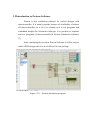
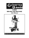
The project is divided into two parts; namely hardware and
software. Each part will be analyzed separately. Proteus simulation
program used to design the electronic circuit with microcontroller as
the main control unit, C code written using MikroC Compiler. The
code was burned to PIC16F877A using PIC k150 programmer. The
circuit was designed, analyzed and tested. The modules considered in
this project are: the keypad unit, mobile phone (DTMF) unit, display
unit, output motor (ULN2803+ Motor) unit.
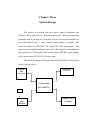
The block diagram of the microcontroller based Electronic door
lock is shown below:
Display unit
LCD 16*2
Keypad
unit
4*4keypad
Control unit
PIC 16F877A
Crystal
DTMF
unit
MT8870
Stepper motor
ULN2803
Figure (3.1) - Block diagram of the door lock
3.1 System Flowchart
10
If #2
From Mobile Phone
If wrong
If right
Start
If #1
Enter Password
Reset
Reset
Password
Wrong
Password
Correct
Lock Open
End
Lock Close
Figure (3.2) – System flowchart
From Keypad
If wrong
If right
3.2 Introduction to Proteus Software
Proteus is best simulation software for various designs with
microcontroller. It is mainly popular because of availability of almost
all microcontrollers in it. So it is a handy tool to test programs and
embedded designs for electronics hobbyist. It is possible to simulate
and test programs of microcontroller in Proteus Simulation Software
[7].
After simulating the circuit in Proteus Software it will be easy to
make a PCB design with it so it could be all in one package .
Figure (3.3) - Proteus simulation program
3.3 MikroC PRO for PIC
The mikroC PRO for PIC is a powerful, feature-rich
development tool for PIC microcontrollers. It is designed to provide
the programmer with the easiest possible solution to developing
applications
for
embedded
systems,
without
compromising
performance or control [8].
PIC and C fit together well, PIC is the most popular 8-bit chip in
the world, used in a wide variety of applications, and C, prized for its
efficiency, is the natural choice for developing embedded systems.
MikroC PRO for PIC provides a successful match featuring highly
advanced IDE, ANSI compliant compiler, broad set of hardware
libraries, comprehensive documentation, and plenty of ready-to-run
examples [8].
Figure (3.4) - MikroC program for PIC
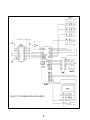
3.4 System Circuit Diagram
The main control unit is PIC16F877A has five ports (A –
13in this project.
B – C – D – E). Port E is not used
DTMF (MT8870) is interfaced to the main control unit
through Port A (A0-A4) as the inputs for the system.
The keypad is interfaced to the main control unit through
Prot B (B0-B7), as the inputs for the system.
A 16*2 LCD is the output for the system that displays the
status of the system; it interfaces to the main control unit
through Prot D (D2-D7).
A motor drive is the output for the system that represents
the
lock
of
the
door.
Motor
drive
connects
to
the
microcontroller using the integrated circuit ULN2803.
ULN2803 interfaces to the main control unit through Prot
C (C0-C3).
Figure (3.5) - Circuit diagram of the door lock controller
15
3.5 k150 Programmer
The USB PIC K150 microcontroller programmer is a lowcost high-performance PIC programmer, support most popular PIC
chip burning Write, read and other functions, use a high-speed USB
communication, ultra-fast programming, programming quality is stable
and reliable [9].
Figure (3.6) - PIC k150 programmer
16
3.6 Dual Tone Multiple Frequency (DTMF)
Dual
Tone
Multi
Frequency
signaling
is
used
for
telecommunication signaling over analog telephone lines in the voicefrequency band between telephone handsets and other communications
devices and the switching center [10].
Dual Tone Multi-Frequency, or DTMF, is a method for
instructing a telephone switching system of the telephone number to be
dialed, or to issue commands to switching systems or related telephony
equipment [10].
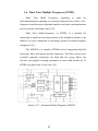
The MT8870 is a complete DTMF receiver integrating both the
band split filter and digital decoder functions. The filter section uses
switched capacitor techniques for high and low group filters, the
decoder uses digital counting techniques to detect and decode all 16
DTMF tone-pairs into a 4-bit code [10].
Figure (3.7) - Functional Block Diagram of MT887
17
External component count is minimized by on chip provision of
a differential input amplifier, clock oscillator and latched three-state
bus interface.
The MT8870 provides full DTMF receiver capability by
integrating both the band-split filter and digital decoder functions into a
single 18-pin. The filter section uses a switched capacitor technique for
both high and low group filters and dial tone rejection [10].
All types of the MT8870 series use digital counting techniques
to detect and decode all the 16 DTMF tone pairs into a 4-bit code
output. The built-in dial tone rejection circuit eliminates the need for
pre-filtering. When the input signal given at pin 2 (IN) in single-ended
input configuration is recognized to be effective, the correct 4-bit
decode signal of the DTMF tone is transferred to Q1 (pin 11), Q2 (pin
12), Q3 (pin 13), Q4 (pin 14) outputs of the DTMF decoder (IC) are
connected to port pins of microcontroller [10].
Figure (3.8) – MT8870 Single-Ended Input Configuration
DTMF keypad is laid out in a 4×4 matrix, with each row
representing a low frequency, and each column representing a high
frequency. Pressing a single key (such as „1‟) will send a sinusoidal
18
tone for each of the two frequencies (697 and 1209 hertz (Hz)). The
original keypads had levers inside, so each button activated two
contacts. The multiple tones are the reason for calling the system multi
frequency. These tones are then decoded by the switching center to
determine which key was pressed [10].
Table (3.1) - DTMF keypad frequencies
(with sound clips)
1209 Hz
1336 Hz 1477 Hz 1633 Hz
697 Hz
1
2
3
A
770 Hz
4
5
6
B
852 Hz
7
8
9
C
941 Hz
*
0
#
D
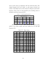
DTMF MT8870 is an IC which converts the numbers at any
mobile to the binary number and each number has low and high
frequency [10].
Table (3.2) - Digit coding
FLOW
697
697
697
770
770
770
852
852
852
941
941
941
697
770
852
941
FHIGH KEY
1209
1
1336
2
1477
3
1209
4
1336
5
1477
6
1209
7
1336
8
1477
9
1209
0
1336
.
1477
#
1633
A
1633
B
1633
C
1633
D
TOE
H
H
H
H
H
H
H
H
H
H
H
H
H
H
H
H
19
Q4 Q3 Q2 Q1
0 0 0
1
0 0 1
0
0 0 1
1
0 1 0
0
0 1 0
1
0 1 1
0
0 1 1
1
1 0 0
0
1 0 0
1
1 0 1
0
1 0 1
1
1 1 0
0
1 1 0
1
1 1 1
0
1 1 1
1
0 0 0
0
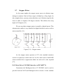
3.7
Stepper Motor
As the name implies the stepper motor moves in distinct steps
during its rotation. Each of these steps is defined by a Step Angle. In
the example above you may notice that there are 4 distinct steps for the
rotor to make a complete 360 degree rotation. This defines the steep
angle at 90 degrees [11].
We can say that a stepper motor is actually a digital motor. This
characteristic makes it very suitable for digital interfaces such as with a
microcontroller [11].
Figure (3.9) – Stepper motor
As the stepper motor operates at 12V, the standard transistor
circuit is required to switch each coil. As the coils create a back EMF
when switched off, a suppression diode on each coil is also required
[11].
3.8.1 Motor Drive (ULN2803) Interface to PIC16F877A
Fortunately the Darlington driver IC ULN2803 can be used to
provide both the NOT and Darlington driver circuits. It also contains
the back EMF suppression diodes so no external diodes are required.
The complete circuit is shown next.
Figure (3.10) – ULN 2803 interface to stepper motor
Before programming, there is another pattern to notice in the stepping
sequence. Look at this table, which show the four different steps required
to make the motor turn [11].
Table (3.3) - Four different steps of stepper motor
Step Coil1 Coil2 Coil3 Coil4
1.
1
0
1
0
2.
1
0
0
1
3.
0
1
0
1
4.
0
1
1
0
1.
1
0
1
0
Coil 2 is always the opposite (or logical NOT) of coil 1.
The same applies for coils 3 and 4. It is therefore possible to cut
down the number of microcontroller pins required to just two by the
use of two additional NOT gates [11].
3.8 Keypad Interface with Microcontroller
Matrix keypad is widely use
21 in our daily life. Each switches
connecting one row and column. So the combinations of rows and
columns make up the 16 inputs [12]. Initially all the switches are open
(not connected). When button pressed switch is now closed
(connected). Then there is a connection between the row and column
[12]. Scanning a keypad in PIC16F877A board in case of 4X4 matrix
keypad both the ends of switches are connected to the port pin. Four
rows and four columns, all sixteen switches have been interfaced using
just eight lines [12].
Row lines (PORTD.0 – PORTD.3) and column lines (PORTD.4
to PORTD.7) connected directly by the port pins in PIC16F877A.
Figure (3.11) – Keypad 4*4
Table (3.4) – Connect keypad in PORTD
4x4 Matrix
Lines
ROW-0
ROW-1
Rows
ROW-2
ROW-4
COLUMN-0
Column
COLUMN-1
PIC16F
Lines
PORTD.0
PORTD.1
PORTD.2
PORTD.3
PORTD.4
PORTD.5
COLUMN-2
COLUMN-3
PORTD.6
PORTD.7
3.9 Interfacing LCD with Microcontroller
Liquid Crystal Display (LCD) is an electronic display module and find a
wide range of applications. A 16x2 LCD
22 display is very basic module and
is very commonly used in various devices and circuits [13].
A PIC Microcontroller can be easily made to communicate with LCD by
using the built in Libraries of MikroC. Interfacing between PIC and LCD
can be 4-bit or 8-bit [14].
In this project 4-bit mode is used 4-bit mode uses only 4 data lines, which
are sending sequentially through data lines DB4 – DB7. The idea of 4-bit
communication is to save as much pins that used to interface
microcontroller with LCD. The 4-bit mode data transmission is most
commonly used [14].
Figure (3.12) – LCD 16*2 Pin Diagram
Table (3.5) - LCD 16*2 Pin Description
Pin No
Function
1
Ground (0V)
2
Supply voltage; 5V (4.7V – 5.3V)
3
Contrast adjustment; through a variable resistor
4
Selects command register when low; and data register when high
5
Low to write to the register; High to read from the register
6
Sends data to data pins when a high to low pulse is given
11
12
4-bit data pins
13
14
15
Backlight VCC (5V)
16
Backlight Ground (0V)
23
Chapter Four
Results and discussions
Name
Ground
Vcc
VEE
Register Select
Read/write
Enable
DB4
DB5
DB6
DB7
Led+
Led-
Chapter Four
Results
Results and discussions
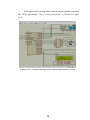
4.1 Simulation Results and discussions
The system design in proteus simulation is shown in Figure (4.1)
Figure (4.1) – System design in proteus program
In the initial state on the LCD display will show only a simple
message indicating that it is expecting a password from keypad or mobile
phone. This is shown in Figure (4.2)
Figure (4.2) – Initial state of system
An authorized user would select option #1. The user is then prompted to
enter the password from keypad as shown in Figure (4.3).
24
Figure (4.3) - System waiting password from keypad
For security purposes, the password is displayed as stars as it is the
convention in such systems. This is illustrated in Figure (4.4).
Figure (4.4) – Entering password to system from keypad
If the correct password is entered, the motor (door lock) will be
activated in order to unlock the door. This is displayed “Lock Open” on
the LCD as shown in Figure (4.5).
25
Figure (4.5) – Motor is activated in order to unlock the door
Then the door will close, the motor (door lock) will be activated in
order to lock the door, this message will be display “Lock Close” on LCD
as shown in Figure (4.6)
Figure (4.6) – Motor is activated in order to lock the door
If the user has no access to the premise, then he/she can contact
the residents or someone who has access to the building. The idea is
that the door could be remotely unlocked by supplying the passwords
over the phone using the DTMF functionality. This is activated by
option #2 then it will display enter password from mobile as shown in
Figure (4.7)
Figure (4.7) - System waiting password from mobile
So the owner will call the mobile phone that attached with
system, he/she must set the mobile phone in the mode of auto answer
when the headset is connect, in this mode the phone will auto answer
after that the owner will enter the DTMF password remotely. The user
requesting entrance will then be granted access to the premises. The
password interring remotely will not be displayed on the LCD for
security issue.
The user requesting entrance will then be granted access to the
premises.
When door is turn to close it will press the reset button so the
system will close the lock and LCD will display “Door locked”.
If the password is wrong when entered from keypad or remotely
the LCD will display "sorry, wrong password" as shown in Figure
(4.8).
Figure (4.8) – System message when entered password is wrong
28
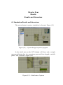
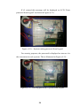
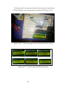
4.2 Results of Hardware construction
The system hardware design is shown in Figure (4.9).
Figure (4.9) – System hardware design
Initially, the LCD will display two options; #1 is enter password from
keypad, #2 is enter password from mobile phone as shown in Figure
(4.10).
Figure (4.10) – Initial state of system
29
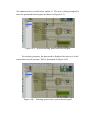
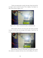
If #1 entered this message will be displayed on LCD “Enter
password from keypad” as shown in Figure (4.11).
Figure (4.11) - System waiting password from keypad
For security purposes, the password is displayed as stars as it is
the convention in such systems. This is illustrated in Figure (4.12).
Figure (4.12) - Entering password to system from keypad
30
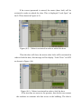
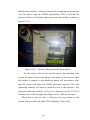
If the correct password is entered, the motor (door lock) will be
activated in order to unlock the door. This is display “Lock Open” on
the LCD as shown in Figure (4.13).
Figure (4.13) – Motor is activated in order to unlock the door
Then the door will close, the motor (door lock) will be activated
in order to lock the door, this message will be display “Lock Close” on
LCD as shown in Figure (4.14).
Figure (4.14) – Motor is activated in order to lock the door
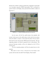
If the user has no access to the premise, then he/she can contact
the residents or someone who has access to the building. The idea is
31
that the door could be remotely unlocked by supplying the passwords
over the phone using the DTMF functionality. This is activated by
option #2 then it will display enter password from mobile as shown in
Figure (4.15).
Figure (4.15) - System waiting password from mobile
So the owner will call the mobile phone that attached with
system, he must set the mobile phone in the mode of auto answer when
the headset is connect, in this mode the phone will auto answer after
that the owner will enter the DTMF password remotely. The user
requesting entrance will then be granted access to the premises. The
password interring remotely will not be displayed on the LCD for
security issue so the message that display on the LCD is Lock open.
When door is turn to close it will press the reset button so the
system will close the lock and LCD will display “Door close”.
32
If the password is wrong when entered from keypad or remotely the
LCD will display sorry wrong password as shown in Figure (4.16).
Figure (4.16) – System message when entered password is wrong
Figure (4.17) - Overall system and desired outputs.
33
Chapter Five
Conclusion and
Recommendations
Chapter Five
Conclusions and Recommendations
5.1 Conclusions
This thesis has presented a low cost door lock system.
Comparing to other biometrics locks that are based on different
authentication method such as fingerprint and eye blinking detection,
this lock has the advantage on cost basis. At the same time, it provides
a reasonably safe access control mechanism.
This system is suitable for most outdoor security protection due
to the fact that it has high discriminative capability during operation
and they are fairly low cost useful system.
5.2 Recommendations
Instead of using the keypad build on the access point to start
remote access which may cause some limitation to this system, the
system may be directly accessed remotely to be more useful and
practical.
The system could be expanded by integrating a call system
with the present system. It could be simplified to allow the system to
directly call the owner of the password from the access point. This
removes the requirement that the person requesting access to have a
mobile phone. The proposed modifications to the system can be
developed with minimal costs and with relatively low operational
costs. The system requires high degrees of security, an example when
children try to gain access to the home when no one is available at
home.
Some feedback can be added to those who open door remotely
about the status of the access point especially when kids access the
entry point. Different types of alarms can be added to alert the
occupants of the premises when the access point is open or someone
tries to be gain access.
References
References
[1] Raj Jain, A Survey of Biometrics Security Systems, http://www.cse.
wustl.edu/~jain/cse571-11/ftp/biomet/index.html, accessed on 7 March
2014.
[2] Rachit Saini Jerry Shim Qi Zhao, alternative house security system, in
March 2014. https://courses.engr.illinois.edu/ece445/projects.asp?term=
120128, accessed on 19 April 2014.
[3] Then Dao Hui “Microcontroller-Based Lock Using Color Security
Code,
in
June
2013,
http://www.scribd.com/doc/188071886/
Microcontroller-based-Lock-Using-Colour-Security-Code#scribd,
accessed on 25 April 2014.
[4] Sadeque Reza Khan, Office Access Control System (OACS),
International Journal of Embedded Systems and Applications (IJESA),
June 2012. http://arnetminer.org/publication/development-of-low-costprivate-office-access-control-system-oacs-3594050.html, accessed on 25
February 2014.
[5] Dogan Ibrahim, PIC BASIC Projects 30 Projects Using PIC BASIC
and PIC BASIC PRO, Linacre House, http://elsevier.com/locate/
permissions, accessed on 25 February 2014.
[6] Martin Bates, introduction to Microelectronic system The
PIC16F877A Microcontroller system security, Elsevier / Newness,
October 2000. http://pic-microcontroller.com/pic-microcontrollers-anintroduction-to-microelectronics-by-martin-bates-e-book, accessed on 15
March2014.
[7] Proteus software, http://geniusdevils.com/2013/03/what-is-proteussoftware/, accessed on 20 March 2014.
[8] MikroC, http://www.mikroe.com/download/eng/documents/compiler
s/mikroc/pro/pic/help/introduction_to_mikroc_pro_for_pic.html accessed
on 20 March 2014.
[9] Manual: “User Manual – PIC K150 Programmer” www.gie.com.my,
accessed on 22 March 2014.
[10] Application Note: MSAN-108. Applications of the MT8870
integrated DTMF Receiver. www.zarlink.com accessed on 18 May 2014.
[11] Stepper Motor, http://en.wikipedia.org/wiki/Stepper_motor accessed
on 15 June 2014.
[12] Keypad, https://iamzxlee.wordpress.com/2013/07/24/4x4-matrix36
keypad/ accessed on 6 November 2014.
[13] Data Sheet: LCD 16x2.pdf, Electronics Reference Design Library,
http://www.engineersgarage.com/electronic-components/16x2-lcdmodule-datasheet accessed on 8 November 2014.
[14] LCD interfacing with PIC Microcontroller, by Ligo George,
http://electrosome.com/lcd-pic-interfacing accessed on 8 November 2014.
Appendices
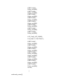
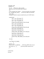
Appendix A
Project code
kp;
char code1[16] ;
char Default_Password[5]={'1', '1', '1', '1','1'};
int i = 0, oldstate;
int Compare_Password();
char get_key();
char Temp_Password_DTMF[5];
int k=0;
//keypad module connections
char keypadPort at PORTB;
//end keypad module connections
//lcd module connections
sbit LCD_RS at RD2_bit;
sbit LCD_EN at RD3_bit;
sbit LCD_D4 at RD4_bit;
sbit LCD_D5 at RD5_bit;
sbit LCD_D6 at RD6_bit;
sbit LCD_D7 at RD7_bit;
sbit LCD_RS_Direction at TRISD2_bit;
sbit LCD_EN_Direction at TRISD3_bit;
sbit LCD_D4_Direction at TRISD4_bit;
sbit LCD_D5_Direction at TRISD5_bit;
sbit LCD_D6_Direction at TRISD6_bit;
sbit LCD_D7_Direction at TRISD7_bit;
void Open_Door()
{
Lcd_Cmd(_LCD_CLEAR);
Lcd_Out(1, 2,"lock Open");
PORTC=0x03;
Delay_ms(500);
PORTC=0x06;
Delay_ms(500);
PORTC=0x0C;
Delay_ms(500);
PORTC=0x09;
Delay_ms(500);
PORTC=0x03;
Delay_ms(500);
PORTC=0x06;
Delay_ms(500);
PORTC=0x0C;
Delay_ms(500);
PORTC=0x09;
Delay_ms(500);
LCD_Cmd(_LCD_CLEAR);
Lcd_out(1, 2,"lock Close");
PORTC=0x0C;
Delay_ms(500);
PORTC=0x06;
Delay_ms(500);
PORTC=0x03;
Delay_ms(500);
PORTC=0x09;
Delay_ms(500);
Delay_ms(500);
PORTC=0x06;
Delay_ms(500);
PORTC=0x03;
Delay_ms(500);
PORTC=0x09;
Delay_ms(500);
return;
}
void code_enter(){
//keypad_init();
oldstate = 0;
kp = 0;
//Reset key code variable
//wait for key to be pressed and released
do
//kp = Keypad_Key_Press(); // store key code in kp variable
kp = Keypad_Key_Click();
// store key code in kp variable
while (!kp);
//prepare value for output, transform key to it's ASCII value
switch (kp){
case 1: kp = 49; break; // 1
case 2: kp = 50; break; // 2
case 3: kp = 51; break; // 3
//case 4: kp = 65; break; // A for 4x4 pad
case 5: kp = 52; break; // 4
case 6: kp = 53; break; // 5
case 7: kp = 54; break; // 6
//case 8: kp = 66; break; // B for 4x4 pad
case 9: kp = 55; break; // 7
case 10: kp = 56; break; // 8
case 11: kp = 57; break; // 9
//case 12: kp = 67; break; // C for 4x4 pad
case 13: kp = 42; break; // *
case 14: kp = 48; break; // 0
case 15: kp = 35; break; // #
//case 16: kp = 68; break; // D for 4x4 pad
}
if(i==0)
{
Lcd_Cmd(_LCD_CLEAR);
}
code1[i] = kp;
//Lcd_Chr(2, i+1, code1[i]);
//Print key ASCII value on Lcd
Lcd_Chr(2, i+1, '*');
//Print key ASCII value on Lcd
i++;
}
void main(){
//int kp;
Keypad_Init();
// Initialize Keypad
TRISC = 0x00;
PORTC = 0x00;
TRISD = 0x00;
PORTD = 0x00;
ADCON1 = 0X07;
//A/D converter
PORTA = 0XFF;
TRISA = 0XFF;
PORTB = 0XFF;
TRISB = 0XFF;
Lcd_Init();
// Initialize LCD
Lcd_Cmd(_LCD_CLEAR);
// Clear display
Lcd_Cmd(_LCD_CURSOR_OFF);
// Cursor off
do {
Lcd_Out(1, 1,"#1 From keypad");
Lcd_Out(2, 1,"#2 From Mobile");
Lcd_Cmd(_LCD_CURSOR_OFF);
kp= Keypad_Key_Click();
if (kp==1)
{
Lcd_Cmd(_LCD_CLEAR);
// clear display
Lcd_Out(1, 1, "Enter Password:");
Lcd_Out(2, 4, "from keypad");
Lcd_Cmd(_LCD_CURSOR_OFF);
i=0;
code_enter();
code_enter();
code_enter();
code_enter();
code_enter();
Compare_Password();
}
if (kp==2)
{
Lcd_Cmd(_LCD_CLEAR);
// clear display
Lcd_Out(1, 1,"Enter Password:");
Lcd_Out(2, 4,"From Mobile");
Lcd_Cmd(_LCD_CURSOR_OFF);
k=0;
for(k=0;k<5;k++){
Temp_Password_DTMF[k]=get_key();}
Compare_Password();
}
}
while(1);}
//int Compare_Password(char *password)
int Compare_Password()
{
int j=0;
char Temp_Password1[5];
for(j=0;j<5;j++)
{
Temp_Password1[j]=code1[j];
}
while (1)
{
int f=1;
int c;
int f2=1;
int c1;
for(c=0;c<5;c++)
if ((code1[c]!=Default_Password[c]) )
f=0;
for(c1=0;c1<5;c1++)
if(Temp_Password_DTMF[c1]!=Default_Password[c1])
f2=0;
if(f==1||f2==1)
{
Open_Door();
break;
}
else
{
Lcd_Cmd(_LCD_CLEAR);
Lcd_Out(1, 4, "Sorry");
Lcd_Out(2, 1, "wrong Password ");
delay_ms(2000);
Lcd_Cmd(_LCD_CLEAR);
return;
}
}
}
char get_key()
{
while (1)
{
if (PORTa.f4==0)
while (1)
{
if (PORTa.f0==1 && PORTa.f1==0 && PORTa.f2==0 &&
PORTa.f3==0)
// if the INPUT = "1"
{
return '1';
}
if (PORTa.f0==0 && PORTa.f1==1 && PORTa.f2==0 &&
PORTa.f3==0)
// if the INPUT = "2"
{
return '2';
}
if (PORTa.f0==1 && PORTa.f1==1 && PORTa.f2==0 &&
PORTa.f3==0)
// if the INPUT = "3"
{
return '3';
}
if (PORTa.f0==0 && PORTa.f1==0 && PORTa.f2==1 &&
PORTa.f3==0)
// if the INPUT = "4"
{
return '4';
}
if (PORTa.f0==1 && PORTa.f1==0 && PORTa.f2==1 &&
PORTa.f3==0)
// if the INPUT = "5"
{
return '5';
}
if (PORTa.f0==0 && PORTa.f1==1 && PORTa.f2==1 &&
PORTa.f3==0)
// if the INPUT = "6"
{
return '6';
}
if (PORTa.f0==1 && PORTa.f1==1 && PORTa.f2==1 &&
PORTa.f3==0)
// if the INPUT = "7"
{
return '7';
}
if (PORTa.f0==0 && PORTa.f1==0 && PORTa.f2==0 &&
PORTa.f3==1)
// if the INPUT = "8"
{
return '8';
}
if (PORTa.f0==1 && PORTa.f1==0 && PORTa.f2==0 &&
PORTa.f3==1)
// if the INPUT = "9"
{
return '9';
}
if (PORTa.f0==0 && PORTa.f1==0 && PORTa.f2==1 &&
PORTa.f3==1)
// if the INPUT = "#"
{
return '#';
}
if (PORTa.f0==1 && PORTa.f1==1 && PORTa.f2==0 &&
PORTa.f3==1)
// if the INPUT = "*"
{
return '*';
}
if (PORTa.f0==0 && PORTa.f1==1 && PORTa.f2==0 &&
PORTa.f3==1)
// if the INPUT = "0"
{
return '0';
}
}
}
}
Appendix B
PIC 16F877A Data Sheet
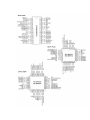
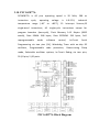
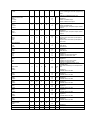
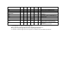
3.10 PIC 16F877A
PIC16F877A is 40 pins operating speed is 20 MHz, 200 ns
instruction
cycle,
temperature
operating
voltage
is
(-40°
+85°C),
15
range
to
4.0-5.5V,
Interrupt
industrial
Sources,35
single-word instructions, All single-cycle instructions except for
program branches (two-cycle), Flash Memory 14.3 Kbytes (8192
words), Data SRAM: 368 bytes, Data EEPROM: 256 bytes, Selfreprogrammable
under
software
control,
In-Circuit
Serial
Programming via two pins (5V), Watchdog Timer with on-chip RC
oscillator,
Programmable
code
protection,
Power-saving
Sleep
mode, Selectable oscillator options, In-Circuit Debug via two pins,
33 I/O pins; 5 I/O ports.
PIC 16F877A Block Diagram
Pin Name
OSC1/CLKI
OSC1
PDIP
Pin#
PLCC
Pin#
TQFP
Pin#
13
14
30
QFN
Pin#
I/O/P
Type
Buffer
Type
I
ST/CM
OS(4)
32
I
CLKI
Description
Oscillator crystal or external clock input.
Oscillator crystal input or external clock
source input. ST buffer when configured
in RC mode; otherwise CMOS.
External clock source input. Always
associated with pin function OSC1 (see
OSC1/CLKI, OSC2/CLKO pins).
O
OSC2/CLKO
OSC2
14
15
31
33
O
—
CLKO
MCLR/VPP
MCLR
1
2
18
I
P
VPP
RA0/AN0
RA0
AN0
RA1/AN1
RA1
AN1
RA2/AN2/VREF-/CVREF
RA2
AN2
VREFCVREF
RA3/AN3/VREF+
RA3
AN3
VREF+
RA4/T0CKI/C1OUT
RA4
T0CKI
C1OUT
ST
18
2
3
3
4
19
20
19
20
I/O
I
4
5
21
21
5
6
22
22
6
7
23
I/O
I
I/O
I
I
O
I/O
I
I
23
I/O
I
O
Oscillator crystal or clock output.
Oscillator crystal output.
Connects to crystal or resonator in
Crystal Oscillator mode.
In RC mode, OSC2 pin outputs CLKO,
which has 1/4 the frequency of OSC1
and denotes the instruction cycle rate.
Master Clear (input) or programming
voltage (output).
Master Clear (Reset) input. This pin is
an active low Reset to the device.
Programming voltage input.
PORTA is a bidirectional I/O port.
TTL
Digital I/O.
Analog input 0.
TTL
Digital I/O.
Analog input 1.
TTL
Digital I/O.
Analog input 2.
A/D reference voltage (Low) input.
Comparator VREF output.
TTL
ST
Digital I/O.
Analog input 3.
A/D reference voltage (High) input.
Digital I/O – Open-drain when configured
as output.
Timer0 external clock input.
Comparator 1 output.
RA5/AN4/SS/C2OUT
RA5
AN4
SS
C2OUT
7
8
24
24
RB0/INT
RB0
INT
RB1
33
36
8
9
34
37
9
10
I/O
TTL
Digital I/O.
External interrupt.
Digital I/O.
RB2
35
38
10
11
I/O
TTL
Digital I/O.
RB3/PGM
RB3
PGM
36
39
11
12
I/O
I
TTL
RB4
37
41
14
14
I/O
TTL
Digital I/O.
Low-voltage ICSP programming enable
pin.
Digital I/O.
RB5
38
42
15
15
I/O
TTL
Digital I/O.
RB6/PGC
39
43
16
I/O
I
I
O
TTL/ST
(1)
I/O
I
40
44
17
17
Digital I/O.
Analog input 4.
SPI slave select input.
Comparator 2 output.
PORTB is a bidirectional I/O port. PORTB
can be software programmed for internal
weak pull-up on all inputs.
TTL/ST
(2)
16
RB6
PGC
RB7/PGD
I/O
I
TTL
Digital I/O.
In-circuit debugger and ICSP programming
clock.
TTL/ST
I/O
I/O
RB7
PGD
(2)
Digital I/O.
In-circuit debugger and ICSP programming
data.
PORTC is a bidirectional I/O port.
RC0/T1OSO/T1CKI
RC0
T1OSO
T1CKI
RC1/T1OSI/CCP2
RC1
T1OSI
CCP2
15
16
32
34
ST
I/O
O
I
Digital I/O.
Timer1 oscillator output.
Timer1 external clock input.
16
18
35
35
I/O
I
I/O
ST
17
19
36
36
I/O
ST
18
20
37
37
I/O
I/O
I/O
RC4/SDI/SDA
RC4
SDI
SDA
RC5/SDO
RC5
SDO
RC6/TX/CK
RC6
TX
CK
RC7/RX/DT
RC7
RX
DT
23
25
42
42
RD0/PSP0
RD0
PSP0
19
RC2/CCP1
RC2
CCP1
RC3/SCK/SCL
RC3
SCK
SCL
RD1/PSP1
RD1
PSP1
RD2/PSP2
RD2
PSP2
RD3/PSP3
RD3
PSP3
RD4/PSP4
RD4
PSP4
RD5/PSP5
RD5
PSP5
24
25
26
26
27
29
21
43
44
I/O
I
I/O
43
I/O
O
44
I/O
O
I/O
1
1
38
I/O
I
I/O
I/O
I/O
38
ST
Digital I/O.
Timer1 oscillator input.
Capture2 input, Compare2 output, PWM2
output.
Digital I/O.
Capture1 input, Compare1 output, PWM1
output.
Digital I/O.
Synchronous serial clock input/output for
SPI mode.
Synchronous serial clock input/output for
I2C mode.
ST
Digital I/O.
SPI data in.
I2C data I/O.
ST
Digital I/O.
SPI data out.
ST
Digital I/O.
USART asynchronous transmit.
USART1 synchronous clock.
ST
ST/T
TL(3)
Digital I/O.
USART asynchronous receive.
USART synchronous data.
PORTD is a bidirectional I/O port or
Parallel Slave
Port when interfacing to a microprocessor
bus.
Digital I/O.
Parallel Slave Port data
20
22
39
39
I/O
I/O
21
23
40
40
I/O
I/O
22
24
41
41
I/O
I/O
27
30
2
2
I/O
I/O
28
31
3
3
I/O
I/O
RD6/PSP6
RD6
PSP6
29
32
4
4
RD7/PSP7
RD7
PSP7
30
33
5
5
RE0/RD/AN5
RE0
8
9
25
I/O
I/O
I/O
I/O
25
I/O
ST/T
TL(3)
ST/T
TL(3)
ST/T
TL(3)
ST/T
TL(3)
ST/T
TL(3)
ST/T
TL(3)
ST/T
TL(3)
ST/T
TL(3)
Digital I/O.
Parallel Slave Port data
Digital I/O.
Parallel Slave Port data.
Digital I/O.
Parallel Slave Port data.
Digital I/O.
Parallel Slave Port data.
Digital I/O.
Parallel Slave Port data.
Digital I/O.
Parallel Slave Port data.
Digital I/O.
Parallel Slave Port data.
PORTE is a bidirectional I/O port.
RD
I
Digital I/O.
Read control for Parallel Slave Port.
AN5
I
Analog input 5.
RE1/WR/AN6
9
10
26
ST/T
(3)
TL
26
RE1
I/O
WR
I
AN6
I
RE2/CS/AN7
10
11
27
Digital I/O.
Write control for Parallel Slave Port.
Analog input 6.
ST/T
TL(3)
27
I/O
RE2
Digital I/O.
CS
I
Chip select control for Parallel Slave Port.
AN7
I
Analog input 7.
VSS
VDD
NC
12, 31
13, 34
6, 29
6, 30,
31
P
—
Ground reference for logic and I/O pins.
P
—
Positive supply for logic and I/O pins.
—
—
These pins are not internally connected.
These pins
should be left unconnected
11, 32
12, 35
7, 28
7, 8,
28, 29
—
1, 17,
28, 40
12,13,
33, 34
13
Legend: I = input O = output I/O = input/output P = power
— = Not used TTL = TTL input ST = Schmitt Trigger input
Note 1: This buffer is a Schmitt Trigger input when configured as the external interrupt.
2: This buffer is a Schmitt Trigger input when used in Serial Programming mode.
3: This buffer is a Schmitt Trigger input when configured in RC Oscillator mode and a CMOS input otherwise.
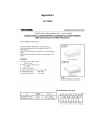
Appendix C
ULN2803
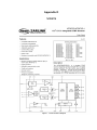
Appendix D
MT8870