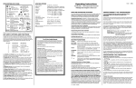
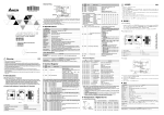
1
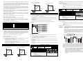
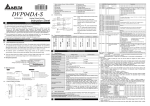
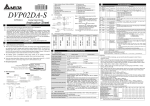
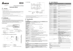
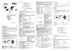
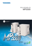
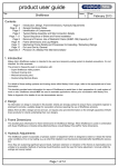
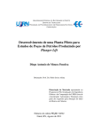
http://www.delta.com.tw/industrialautomation/
DVP04TC-S
Thermocouple Sensors
Instruction Sheet
2.3
3.2
1. Status indicator (Power, RUN and ERROR)
8. Extension port
2. Model Number
9. Extension Clip
3. DIN rail clip
10. DIN rail location (35mm)
Power Specification
4. I/O terminals
11. RS-485 Communication port
5. I/O point indicator
6. Extension hole of the extension unit mounting
pins
7. Specification Label
12. Extension Clip
13. DC Power input
supplied with your
thermocouple sensor.
Thermocouple
This is an OPEN TYPE PLC.
-
Also, it is equipped with protective methods such as
Shielded*1
L+
L-
Cold-junction
Compensation
*2
Make sure that the DVP04TC-S is properly grounded
2
terminal of DVP04TC-S
AG
terminal of
power module
*3
System
Grounding
, to avoid any electromagnetic noise.
power supply module and
5V
Check all the wiring prior to power up.
Do NOT touch internal circuit within 1 minute after power is OFF.
+15V
DC/ DC
24+
24-
Converter
AG
-15V
four thermocouple sensors (Type J/K).
No Connection ( ) terminals.
60℃
The DVP04TC-S series can read/write the data by using
instructions FROM / TO via DVP-PLC SS/SA/SX/SC MPU program.
There are 49 CR (Control
Power supply and
DVP04DA-S
V+
I+
COM
FG
V+
I+
COM
FG
V+
I+
COM
FG
V+
I+
COM
FG
main processing units are sold separately.
The DVP04TC-S works with both Centigrade and Fahrenheit.
DVP02DA-S
V+
I+
COM
FG
V+
I+
COM
FG
Register) in each module and 16 bits for each register.
DVP04TC-S thermocouple sensor can update software version by RS-485.
Terminals of analog module
DVP04AD-S
DVP04PT-S
V+
I+
COM
FG
V+
I+
COM
FG
DVP04TC-S
L+
LIFG
L+
LIFG
V+
I+
COM
FG
V+
I+
COM
FG
L+
LIFG
L+
LIFG
The input resolution for
DVP06XA-S
DVP08RT-S
V+
I+
COM
V+
I+
COM
V+
I+
COM
V+
I+
COM
V+
I+
COM
V+
I+
COM
L+
LSLG
L+
LSLG
L+
LSLG
L+
LSLG
L+
LL+
LL+
LL+
LL+
LL+
LL+
LL+
L-
Analog Input /Output Module Spec.
Barcode, series and version
MODEL:
POWER INPUT :
24Vdc 2W
THERMOCOUPLES: TYPE J , K
RESOLUTION: 14 BITS
V X .X
3.1
Model Explanation
Serial Number
Product Series
Input + Output points
Production series
Production week
Production year (2005)
Production place (Taoyuan)
Serial number of version
Production Model
S: for SS/SA series MPU
Model type
AD: Analog input module
DA: Analog output module
PT: Platinum temperature sensors (PT-100)
2.2
TC: Thermocouple sensors (Type J/K)
XA: Analog input/output mixed module
RT: Resistor Thermocouple(NTC)
Function Specifications
Product Profile and Outline
Power Supply Voltage
24 VDC(20.4VDC~28.8VDC) ( –15%~+20%)
Analog Input Channel
4 channels per module
Sensors Type
J-type or K-type thermocouple
Temperature Input Range
J-type: -100°C~700°C
K-type: -100°C~1000°C
J-type: -148°F~1292°F
K-type: -148°F~1832°F
Digital Conversion Range
J-type: K-1000~K7000
K-type: K-1000~K10000
J-type: K-3280~K12920
K-type: K-1480~K18320
Resolution
14 bits(0.1°C)
14 bits(0.18°F)
Overall Accuracy
±0.5% of full scale of 25°C(77°F), ±1% of full scale during 0~55°C
(32~131°F)
Response Time
250 ms × channels
Isolation Method
Isolation between digital and analog circuitry. There is no isolation between
channels.
Digital Data Format
2’s complement of 16-bit, (13 Significant Bits)
Average Function
Yes (CR#2~CR#5 may be set and the range is K1~K4096)
Self Diagnostic Function
Yes
Communication Mode (RS-485)
MODBUS ASCII/RTU Mode. Communication baud rate of 4800 / 9600 /
19200 / 38400 / 57600 / 115200. For ASCII mode, date format is 7Bits,
even, 1 stop bit (7 E 1). For RTU mode, date format is 8Bits, even, 1 stop
bit (8 E 1). The RS-485 is disabled when the DVP04TC-S is connected in
series to an MPU.
Connection to a DVP-PLC MPU in
Series
When DVP04TC-S modules are connected to an MPU, the modules are
numbered from 0 – 7. 0 is the closest to the MPU and 7 is the farthest. The
Maximum number of modules is 8 modules and they do not occupy any
digital I/O points of the MPU.
4
5
1
3.00
25.20
60.00
L+
3.4
6
11
7
60.00
3.00
C
H
SLD 1
L-
Fahrenheit (°F)
Centigrade (°C)
Platinum Temperature Module (04TC)
0 4 T C - S0 T 5 0 20 0 01
MADE I N XXXXX X
Model
CH2 average number
H 409A
#5
H 409B ○ R/W
H 409C ╳ R
H 409D ╳ R
H 409E ╳ R
CH3 average number
L- C
H
SLD 2
8
10
12
14
●
●
L+
C
LH
SLD 3
90.00
9
13
●
L+
L- C
H
SLD 4
2
90.00
3
●
●
3
4.00
Unit: mm
b4
b3
CH2
CH2 average degrees(°C)
CH3 average degrees(°C)
Average degrees for channels CH1~CH4.
(unit: 0.1 degrees C)
Average degrees for channels CH1~CH4.
(unit: 0.1 degrees F)
H 409F
H 40A2
╳
R
CH1 average degrees(°F)
#11
H 40A3
╳
R
CH2 average degrees(°F)
#12
H 40A4
╳
R
CH3 average degrees(°F)
#13
H 40A5
╳
R
#14
H 40A8
╳
R
#15
H 40A9
╳
R
#16
H 40AA ╳
R
#17
H 40AB ╳
R
#19
H 40AE ╳
R
#20
H 40AF ╳
R
#21
H 40B0
╳
R
#22
H 40B1
╳
R
H 40AE ○
H 40AF ○
R
CH4 average degrees(°F)
Present temperature of
CH1 (°C)
Present temperature of
CH2 (°C)
Present temperature of channels CH1~CH4. (unit: 0.1 degrees C)
Present temperature of
CH3 (°C)
Present temperature of
CH4 (°C)
Reserved
Present temperature of
CH1 (°F)
Present temperature of
CH2 (°F)
Present temperature of channels CH1~CH4. (unit: 0.1degrees F)
Present temperature of
CH3 (°F)
Present temperature of
CH4 (°F)
Reserved
CH1 OFFSET Value
R
CH2 OFFSET Value
H 40B0 ○
H 40B1 ○
R
CH3 OFFSET Value
R
╳
R
CH4 OFFSET Value
Reserved
Error status
○ R/W
#31
H 40B5
#32
H 40B6
○ R/W
#33
H 40B7
○ R/W
b0
CH1
CH4 average number
CH4 average degrees(°C)
#23
#24
b1
The number of readings used for “average” temperature on channels CH1~CH4.
Setting range is K1~K4096 and factory setting is K10.
R
#18
b2
CH1 average degrees(°C)
Communication address
setting
Communication baud rate
setting
Reset to factory setting
●
L+
b5
╳
#27
#28~#29
#30 H 40B4
STANDARD SPECIFICATIONS
b6
Thermocouple type
#4
#8
b7
○ R/W
CH1 average number
#7
b8
Reserved
CH4
CH3
Example: Setting of CH1
1. b0: set 0 to use J-type and set 1 to use K-type
2. b1: Reserved.
3. b2: Reserved.
○ R/W
○ R/W
#6
b15 b14 b13 b12 b11 b10 b9
System used, DVP04TC-S model code = H 8B
○ R/W
#26
Nameplate Explanation
PLC model
Input power Supply Spec.
Register name
Explanation
Model type
H 4099
#25
Centigrade is 0.1 degrees and for Fahrenheit is 0.18 degrees.
3
R
H 4098
to system earth ground.
Warning: DO NOT connect wires to the
Class 3 Grounding
(100 of less)
2.4
Latched
○
#3
#10
Use copper conductor only,
The DVP04TC-S allows the connection of
H 4096
H 4097
#2
thermocouple sensors module
Model Explanation and Peripherals
Thank you for choosing DELTA’s DVP Series PLC.
#0
#9
INTRODUCTION
2.1
terminal of
Note 3: Please connect
SLD
Do NOT connect the AC main circuit power supply to any of the input/output terminals, or it may
DVP04TC-S platinum temperature sensors
RS-485
CR
Parameter
No. address
#1
location for noise suppression.
CH4
-
CR (Controlled Register)
in-lbs).
Note 2: Terminal SLD is a grounding
+
the PLC.
Tighten
torque of 1.95 kg-cm (1.7
MUX
SLD
Thermocouple
some special tools or keys to open the enclosure, in order to prevent hazard to users or damage
Follow the DVP-PLC MPU.
All places between terminals and ground comply with the spec.
PLC terminal screws to a
100
L+
L-
The PLC should be kept in an enclosure away from airborne dust,
humidity, electric shock risk and vibration.
damage the PLC.
CH1
+
Make sure that power is OFF before wiring.
Environment Condition
Static Electricity Prevention
4
External wiring
Shielded*1
2W at 24 VDC (20.4VDC~28.8VDC) ( -15 % ~ +20 %)
14. Extension port
WARNING
Always read this instruction thoroughly before using the DVP04TC-S.
Maximum Power Consumption
Environment Condition
Note 1: Use only the wires that are
1
Other Specification
#34
Adjust offset value of channels CH1~CH4. The range is -1000~+1000 and
factory setting is K0. (unit: 0.1 degrees C)
Data register stores the error status, refer to fault code chart for details.
RS-485 communication address.
Setting range is 01~255 and factory setting is K1
Communication baud rate (4800, 9600, 19200, 38400, 57600 and 115200 bps).
b0: 4800 bps (bit/sec).
b1: 9600 bps (bit/sec). (factory setting)
b2: 19200 bps (bit/sec).
b3: 38400 bps (bit/sec).
b4: 57600 bps (bit/sec).
b5: 115200 bps (bit/sec).
b6~b13: Reserved.
b14: switch between low bit and high bit of CRC code (only for RTU mode)
b15: RTU mode.
b15 b14 b13 b12 b11 b10 b9 b8 b7 b6 b5 b4 b3 b2 b1 b0
Definition of ERR
CH4
CH3
CH2
CH1
LED
Example: Setting of CH1
1. b0 Reserved
2. b1 Reserved
3. b2: Set to 1 and PLC will be reset to factory settings.
Definition of ERR LED: b12~b15=1111(factory settings)
1. b12 corresponds to CH1: when b12=1, scale exceeds the range or external
contact has no connection, ERR LED flashes.
2. b13 corresponds to CH2: when b13=1, scale exceeds the range or external
contact has no connection, ERR LED flashes.
3. b14 corresponds to CH3: when b14=1, scale exceeds the range or external
contact has no connection, ERR LED flashes.
4. b15 corresponds to CH4: when b15=1, scale exceeds the range or external
contact has no connection, ERR LED flashes.
Display software version in hexadecimal. Example: H 010A = version 1.0A.
Software version
H 40B4 ○ R
#35~#48
System used
○ means latched.
╳ means not latched.
R means can read data by using FROM instruction or RS-485.
W means can write data by using TO instruction or RS-485.
Explanation:
1. CR#0: The PLC model type.
2. CR#1: Used to set the working mode of four channels (CH1~CH4). There are 2 modes (J-type
Command
Explanation
Temperature mode: (Fahrenheit)
and K-type) for each channel and can be set individually. For example, If you want to set
J-type thermocouple
CH1~CH4 as following: CH1: mode 0 (b2~b0=000), CH2: mode 1(b5~b3=001), CH3: mode
K-type thermocouple
Digital output
0(b8~b6=000) and CH4: mode 1(b11~b9=001), you should set CR#1 to H0208. The higher
bits (b12~b15) will be reserved and the factory setting is H0000.
Digital output
+12920
D: When assigning bit operand, K1~K4 can be used for 16-bit and K5~K8 can be used
for 32-bit.
The available range is K1~K4096 and factory setting is K10. (Note: When PLC sets average
Please refer the following footnote for calculationof special module number.
times via TO/DTO instructions, please use rising-edge/falling-edge detection instruction (such
as LDP and LDF) to get correct average times.)
The average temperature is calculated from
multiple temperature readings. Example: If CR#2 is 10, the temperature in CR#6 will be the
average of the last 10 readings in CH1.
5. CR#10 ~ CR#13: The average temperature (°F).
The average temperature is calculated from
multiple temperature readings. Example: If CR#2 is 10, the temperature in CR#12 will be the
average of the last 10 readings in CH1.
Temperature
input
Temperature
input
-148 F
-148 F
+1292 F
X
6
Initial PLC Start-up
LED display:
7. CR#18, CR#23, CR#28, CR#29 are reserved.
2. No errors= POWER LED on and ERROR LED off.
Low Voltage error (lower than 19.5V), ERROR LED will blink continuously till the power supply
rises above 19.5V.
LED should blink.
Command
Explanation
4. After receiving the first RS-485 instruction the A/D LED or D/A LED will blink.
FROM
K0
TO
K0
FROM
K0
FROM
K0
FROM
K0
FROM
K0
M1002
= H8B D0
b3:38400 bps, b4:57600 bps,
b5:115200 bps, b6~b13: Reserved, b14: switch between low bit and high bit of CRC code
Footnote
END
If the model type is DVP04TC-S. Reading the average temperature (°C) of CH1~CH4 (4 data)
from CR#6~CR#9 and save them into D20~D23.
16. The corresponding parameters address H 4096~H 40C7 of CR#0~CR#48 may provide users
to read/write data via RS-485 communication.
-100 C
Reading the present temperature (°F) of CH1~CH4 (4 data) from CR#19~CR#22 and save them
into D34~D37.
7
78
Digital output
+700 C
-1000
Reading the present temperature (°C) of CH1~CH4 (4 data) from CR#14~CR#17 and save them
into D30~D33.
Related Instructions Explanation
API
m1
m2
D
n
Temperature
input
Temperature
input
-100 C
+1000 C
-1000
¼
C
D
E
F
¼
¼
¼
¼
¼
16-bit instruction (9 STEPS)
Continuous
Pulse
TO
TOP
execution
execution
32-bit instruction (17 STEPS)
Continuous
Pulse
DTO
DTOP
execution
execution
Flag: When M1083=On, it allows
to insert interrupt during
FROM/TO.
Refer to following for detail.
m1: the number of special module. m2: the number of CR (Control Register) of special
module that will be wrote in. S: the data to write in CR. n: the data number to write in
one time.
The rule of instruction operand:
m1: arrangement number of special module. The number of special module that
connects to PLC MPU. The numbering order of special module from the near to
the distant of MPU is from 0 to 7. The maximum is 8 special modules and won’t
occupy I/O point.
D
FROM
Special module CR
data read out
P
Applicable model
SS SA/SX/SC EH
Bit device
Word device
16-bit instruction (9 STEPS)
X Y M S K H KnX KnY KnM KnS T C D E F
Continuous
Pulse
FROM
¼ ¼
¼ ¼
¼
¼
¼
¼ ¼
¼
¼
¼
¼ ¼
Note: The usage range of operand m1 is 0~7.
The usage range of operand m2: SS/SA: 0-48, EH:
0-254.
The usage range of operand n: SS/SA: n= 1~(49-m2),
EH: 1~(255-m2).
SS series model doesn’t support pulse execution
instruction (FROMP, DFROMP).
execution
FROMP
execution
32-bit instruction (17 STEPS)
DFROM
Continuous
Pulse
DFROMP
execution
execution
Flag: When M1083=On, it allows to
insert interrupt during FROM/TO.
Refer to following for detail.
CR #9
Specified CR number
The number of transmission groups n. The meaning of n=2 of 16-bit instruction
and n=1 of 32-bit are the same.
Specified device
Reading the average temperature (°F) of CH1~CH4 (4 data) from CR#10~CR#13 and save them
into D24~D27.
a. Communication baud rate: 4800, 9600, 19200, 38400, 57600, 115200 bps.
b. Communication format: ASCII mode is 7Bit, even bit, 1 stop bit (7 E 1). Communication
format of RTU mode is 8Bit, even bit, 1 stop bit (8 E 1).
c. Function code: 03H—read data from register. 06H—write a WORD into register.
10H—write many WORDs into register.
+10000
¼
CR #10
15. CR#35~ CR#48: Reserved for internal system use.
+7000
¼
T
Upper 16-bit Lower 16-bit
The averaging number for CH1~CH4 will be D10~D13.
Digital output
¼
Explanation:
14. CR#34: software version.
K-type thermocouple
KnX KnY KnM KnS
If using FROM/TO instruction, the unit of read/write of CR is one number for one
time. If using DFROM/DTO instruction, the unit of read/write of CR is two numbers
in one time.
Reading the model type of extension module K0 (should be H8B for DVP04TC-S model type).
J-type thermocouple
H
¼
¼
¼
¼
m2: the number of CR. Built in 16-bit of 49 groups memory of special module is
called CR (Control Register). The number of CR uses decimal digital (#0~#48). All
running status and setting values of special module has included.
13. CR#33: Used to reset the settings of CR registers to factory settings.
Temperature mode: (Centigrade)
Word device
K
¼
¼
¼
¼
S: When assigning bit operand, K1~K4 can be used for 16-bit and K5~K8 can be used
for 32-bit.
M1000
12. CR#32: RS-485 communication baud rate: 4800, 9600, 19200, 38400, 57600 and 115200.
Temperature/Digital Characteristic Curve
S
DVP-series PLC uses this instruction to write data into CR of special module.
Example:
11. CR#31: RS-485 communication address. Setting range is 01~255 and factory setting is K1.
(only for RTU mode), b15: ASCII / RTU mode. For ASCII mode, date format is 7Bits, even, 1
stop bit (7 E 1). For RTU mode, date format is 8Bits, even, 1 stop bit (8 E 1).
M
Applicable model
SS SA/SX/SC EH
3. DVP04TC-S connected to PLC MPU in series = RUN LED on MPU will be lit and A/D LED or D/A
Fault description
Content
b15~b8
b7
b6
b5
b4
b3
b2
b1
b0
Power source abnormal
K1(H1)
0
0
0
0
0
0
0
1
Analog input value error
K2(H2)
0
0
0
0
0
0
1
0
Setting mode error
K4(H4)
0
0
0
0
0
1
0
0
Offset/Gain error
K8(H8)
0
0
0
0
1
0
0
0
Reserved
Hardware malfunction
K16(H10)
0
0
0
1
0
0
0
0
Digital range error
K32(H20)
0
0
1
0
0
0
0
0
Average times setting error K64(H40)
0
1
0
0
0
0
0
0
Instruction error
K128(H80)
1
0
0
0
0
0
0
0
Note: Each fault code will have corresponding bit (b0~b7). Two or more faults may happen at the same time. 0
means normal and 1 means fault occurs.
b0:4800bps, b1:9600bps (factory setting), b2:19200bps,
Special module CR
data write in
P
Note: The usage range of operand m1 is 0~7.
The usage range of operand m2: SS/SA: 0-48, EH:
0-254.
The usage range of operand n: SS/SA n= 1~(49-m2),
EH: 1~(255-m2).
For SS series, it doesn’t support pulse execution
instruction (TOP, DTOP)
5. If the input or output exceeds the upper or lower bounds, then the ERROR LED will blink.
10. CR#30 is a fault code register. Refer to the following chart.
5
Y
m1
m2
S
n
1. Upon power-up, the ERROR LED will light for 0.5 seconds the POWER LED will light continuously.
unit is 0.1 degrees C. The definition of OFFSET is Actual temperature = temperature
measured by DVP04TC-S – OFFSET value.
TO
D
Bit device
-1480
-1480
8. CR#19 ~ CR#22: display present temperature (°F) of CH1~CH4 input signal.
API
79
+1832 F
6. CR#14 ~ CR#17: display present temperature (°C) of CH1~CH4 input signal.
9. CR#24 ~ CR#27: display offset value of channels CH1~CH4. The range is -1000~+1000 and
module that will be read. D: the location to save reading data. n: the data number of
reading one time.
DVP-series PLC uses this instruction to read CR data of special module.
+18320
3. CR#2 ~ CR#5: Used to set the times of input readings for the average temperature calculation.
4. CR#6 ~ CR#9: The average temperature (°C).
m1: the number for special module. m2: the number of CR (Control Register) of special
Specified CR
Specified device Specified CR
D0
D1
D2
CR #5
D0
D1
D2
CR #5
CR #6
CR #7
D3
D4
CR #8
CR #9
D3
D4
CR #8
CR #9
D5
CR #10
D5
CR #10
16-bit command when n=6
CR #6
CR #7
32-bit command when n=3
In SS series models, flag M1083 is not provided. When FROM/TO instruction is
executed, all interrupts (including external or internal interrupt subroutines) will be
disabled. All interrupts will be executed after FROM/TO instruction is completed.
Besides, FROM/TO instruction also can be executed in the interrupt subroutine.
The function of the flag M1083 (FROM/TO mode exchange) provided in SA/EH series
models:
1. When M1083=Off, FROM/TO instruction is executed, all interrupts (including
external or internal interrupt subroutines) will be disabled. All interrupts will be
executed after FROM/TO instruction is completed. Besides, FROM/TO
instruction also can be executed in the interrupt subroutine.
2. When M1083=On, if an interrupt occurs while FROM/TO instruction has been
programmed, FROM/TO instruction will be interruptted to execute the
interrupt. However, FROM/TO instruction cannot be executed in the interrupt
subroutine.