1
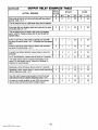
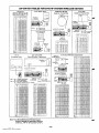
Section
1.
GENERAL
information
.............. 4
Arming Fundions .. ...... ....... ..... ........ .. ......... ... .....l9
Panic Keys ..... ..... ... .... ...... ....... ..... .... ................l9
mouBLEmNDmioNs
. ....... ..... .... ... .... ....... .... ......2o
General information . ................. ......... .................2O
'Check" and"Batiey" Dispiays .... ......... ... .............2O
Power Faiiure .....................................................2O
Other Dispiays (Fixed Word Consoles) ....................2O
Section
6. PROGRAMMiNG
THE SYSTEM.......21
General information . ....... ..... .... ..... .... ..... ..... .......21
Summary of Programming Commands ..................... 22
Speciai Messages . ........ ..... .... ........... ... .... ..... .....22
PROGRAMMiNG DATA FiELDS ................................23
ALPHA Description
ENTRiES ..... ........ .................3O
Assigning Zone Descriptors.., ...............................3O
Entering Zone Descriptors ....................................3O
Adding Custom Words .... ..... ........ ....... ... .... ..........3l
introduction ............. .... ...... . ...... .... ......... ..... .... ....4
Zone Characteristics .............................................5
Section
2. SYSTEM CONFIGURATIONS . . . . . . . . . . 6
zoNEwPE Definitions ........................................6
HARD WiRED ZONES...............................................7
Basic Contm~s Zones ......... ... .... ..... ......... ......... ....7
wiREDzoNE ExPANsDN ... .... ......... ..... ............ ......8
Nos. 4219and 4229 Expansion Units ........ ...............8
WiRELESS EXPANSON, -5700 RF SYSTEM- ...........9
General ...... .... ... .......... ....... ............. ...... ..... ........9
Supervision .......... ........ ....................... ........ ........9
House identification ..............................................9
Transm”kter identification . ...... ....... ..... .... ..... .... .......9
WiRELESS EXPANSiON, -5800 RF SYSTEM-. ... .....10
General .. .... .... ... .... .... ..... ........ ..... ........ ............. 10
ALPHA FiXED Dictionary
(For Entering Zone Descriptors) ................................32
CHA~CTER (ASCll) CHART ...... ... ...... ... ........... ......32
Section 7. SYSTEM COMMUNICATION . . . . . . . ...33
Re~ti Reformats
..... ..... .... ..... .... .. ......... ........33
Section
8. REMOTE PROGRAMMiNG
AND
CONTROL (DOWNLOADING)........34
Supervision ........... .... ........ ........................ ........ 10
House identification ............................................ 10
Transmitter identification ..... ..... .... ... ...... ... ...... ..... 10
Transmitter System installation Options .................11
RELAY OUTPUTS .................................................. 12
Nos. 4204 and 4229 Output Reiay Modules .............. 12
4204Setup . .......... ... .... .... ..... ................. ...........l2
4229 Setup ..... .... ..... ........... ...... ......... ......... .... ..l2
Relay Basics ....... ....... ........ ..... ...... .................. ..l3
Section
3. MOUNTING THE CONTROL,
LOCK, & PC BOARD . . . . . . . . . . . . . . . . . 14
Mounting the Cabinet ...... ... .. ....... .... ..... .... ...........l4
installing the Lock (if Used) ...... ... ...... ... ..... .... ....... 14
installing the control’s Circuit Board Alone,
or (if used), with a 4219, 4229, or 4204 .................... 14
installing Controi and RF Receiver Circuit Boards
Together, inthe Same Cabinet .. ..... ......... .... .......... 15
Section
4. WIRING & POWERiNG
THE SYSTEM . . . . . . . . . . . . . . . . . . . . . . . . . . 16
Generai information . .... ..... ......... ........ . .... ..... .......34
Equipment Required ............................................34
Programming .. ...... ... ...... ......... ......... .... ..............34
Remote Programming Advisory Notes .....................34
Section 9. TESTiNG THE SYSTEM . . . . . . . . . . . . ...36
Procedure ..... ................................ ....... .............36
Section
10. SPECIFICATIONS
&
ACCESSORIES
. . . . . . . . . . . . . . . . . . . ...39
sPEciFicATioNs ................................... ...... ... .....39
ACCESSORIES (COMPATIBLE DEVICES). ................41
FCC STATEMENTS . . . . . . . . . . . . . . . . . . . . . . . . . . . . . . . ...48
CANADiAN DOC STATEMENT . . . . . . . . . . . . . . . . . . ...49
Limitations
OF THiS ALARM SYSTEM . . . . . . . . 50
LiMiTED WARRANTY . . . . . . . . . . . . . . . . . . . . . . . . . . . . ...51
Grounding the System ......................................... 16
Terminals andtinne@bns .. ...... ....... .......... .... .....l6
Power. up Procedure . ...... ....... ..... ......... ............. ..l7
Section 5. SYSTEM OPERATION . . . . . . . . . . . . . . ...18
SECURi~~DES
. ... .... ..... .... ..... ........ .......... ........ 18
Master Code ...................................................... 18
User Codes ..... .... ..... ......... ........... .......... ........... 18
KEYPAD FuNcmoNs ...... ..... .. ...... ..... .... .........<.... ..l8
Generai information ...... ....... ...... ... ...... .............. .. 18
Dlaarams
TROUBLESHOOTiNG
GUiDE . . . . . . . . . . . . . . . . . . . ...37
OUTPUT RELAY
EXAMPLES
TABLE .. .... .... ....44
DiP SWiTCH TABLES FOR
WiRELESS
DEViCES . . . . . . . . . . . . . . . . . . . . . . . . . . . . . . . 46
SUMMARY OF CONNECTiONS
Diagram ... ... .. 47
PROGRAMMiNG FORM . . . . . . . . . . . . . . . . . .. Centerfold
–3-
www.PDF-Zoo.com
and Tabi e s