1
Addition of new 5800 series transmitters with this
control panel is prohibited, other than for repair of
existing installations. Non-permitted use voids U.S.
warranty.
—
m
IQ
2NDEMC0
www.PDF-Zoo.com
CONGRATULATIONS
!
on your purchase of the Ademco via30 System
The purpose
of these Installation
Instructions
is to give you
system, and provide instructions for installing a basic system.
a brief
overview
of
the ~
As always, ADEMCO is there for YOU! Our SALES and TECHNICAL SUPPORT staff are eager
to assist you in any way they can, so don’t hesitate to call, for any reason!
East Coast Technical Support:
West Coast Technical Support:
Technical Support Fax Number:
1-800-645-7492 (8 a.m.-6 p.m. E.S.T.)
1-800-458-9469 (8 a.m.-5 p.m. P.S. T.)
l-8@447-50t36
PLEASE,
Before
you call Technical
be sure you have:
s
Checked
“
Determined
“
Verified
c
Noted the proper model number of this product, and the version
along with any documentation that came with the product.
“
Your
connections
that the power
your
Ademco
Having this
effectively.
Again,
all wiring
Support,
supply and backup
programming
customer
information
and fuses.
information
number
handy
CONGRATULATIONS,
where
and/or
will
battery
make
are supplying
applicable.
company
name.
it
for
easier
and WELCOME
proper voltages.
us
to
level (if known)
serve
you
ABOARD!
The Ademco via30 System
Can Support 2 EOLR Wired Zones
and
(when used
with
appropriate
wireless
receiver
and/or
wired
expansion
Up to a Total of 30 Expansion Zones
(Including
up to: 30 Wireless,
and/or
s Additional
Wired)
and
(when
used
with
appropriate
output
relay
unit)
2 or 4 Output Relays
FOR YOUR CONVENIENCE,
an easily removable Programming
Form
has been included at the center of this manual.
This system is not California State Fire Marshall approved
and, as such, should not be used for fire protection in California
(or other areas requiring such acceptance).
www.PDF-Zoo.com
-2-
unit)
quickly
and
Section
1.
GENERAL
information
.............. 4
Arming Fundions .. ...... ....... ..... ........ .. ......... ... .....l9
Panic Keys ..... ..... ... .... ...... ....... ..... .... ................l9
mouBLEmNDmioNs
. ....... ..... .... ... .... ....... .... ......2o
General information . ................. ......... .................2O
'Check" and"Batiey" Dispiays .... ......... ... .............2O
Power Faiiure .....................................................2O
Other Dispiays (Fixed Word Consoles) ....................2O
Section
6. PROGRAMMiNG
THE SYSTEM.......21
General information . ....... ..... .... ..... .... ..... ..... .......21
Summary of Programming Commands ..................... 22
Speciai Messages . ........ ..... .... ........... ... .... ..... .....22
PROGRAMMiNG DATA FiELDS ................................23
ALPHA Description
ENTRiES ..... ........ .................3O
Assigning Zone Descriptors.., ...............................3O
Entering Zone Descriptors ....................................3O
Adding Custom Words .... ..... ........ ....... ... .... ..........3l
introduction ............. .... ...... . ...... .... ......... ..... .... ....4
Zone Characteristics .............................................5
Section
2. SYSTEM CONFIGURATIONS . . . . . . . . . . 6
zoNEwPE Definitions ........................................6
HARD WiRED ZONES...............................................7
Basic Contm~s Zones ......... ... .... ..... ......... ......... ....7
wiREDzoNE ExPANsDN ... .... ......... ..... ............ ......8
Nos. 4219and 4229 Expansion Units ........ ...............8
WiRELESS EXPANSON, -5700 RF SYSTEM- ...........9
General ...... .... ... .......... ....... ............. ...... ..... ........9
Supervision .......... ........ ....................... ........ ........9
House identification ..............................................9
Transm”kter identification . ...... ....... ..... .... ..... .... .......9
WiRELESS EXPANSiON, -5800 RF SYSTEM-. ... .....10
General .. .... .... ... .... .... ..... ........ ..... ........ ............. 10
ALPHA FiXED Dictionary
(For Entering Zone Descriptors) ................................32
CHA~CTER (ASCll) CHART ...... ... ...... ... ........... ......32
Section 7. SYSTEM COMMUNICATION . . . . . . . ...33
Re~ti Reformats
..... ..... .... ..... .... .. ......... ........33
Section
8. REMOTE PROGRAMMiNG
AND
CONTROL (DOWNLOADING)........34
Supervision ........... .... ........ ........................ ........ 10
House identification ............................................ 10
Transmitter identification ..... ..... .... ... ...... ... ...... ..... 10
Transmitter System installation Options .................11
RELAY OUTPUTS .................................................. 12
Nos. 4204 and 4229 Output Reiay Modules .............. 12
4204Setup . .......... ... .... .... ..... ................. ...........l2
4229 Setup ..... .... ..... ........... ...... ......... ......... .... ..l2
Relay Basics ....... ....... ........ ..... ...... .................. ..l3
Section
3. MOUNTING THE CONTROL,
LOCK, & PC BOARD . . . . . . . . . . . . . . . . . 14
Mounting the Cabinet ...... ... .. ....... .... ..... .... ...........l4
installing the Lock (if Used) ...... ... ...... ... ..... .... ....... 14
installing the control’s Circuit Board Alone,
or (if used), with a 4219, 4229, or 4204 .................... 14
installing Controi and RF Receiver Circuit Boards
Together, inthe Same Cabinet .. ..... ......... .... .......... 15
Section
4. WIRING & POWERiNG
THE SYSTEM . . . . . . . . . . . . . . . . . . . . . . . . . . 16
Generai information . .... ..... ......... ........ . .... ..... .......34
Equipment Required ............................................34
Programming .. ...... ... ...... ......... ......... .... ..............34
Remote Programming Advisory Notes .....................34
Section 9. TESTiNG THE SYSTEM . . . . . . . . . . . . ...36
Procedure ..... ................................ ....... .............36
Section
10. SPECIFICATIONS
&
ACCESSORIES
. . . . . . . . . . . . . . . . . . . ...39
sPEciFicATioNs ................................... ...... ... .....39
ACCESSORIES (COMPATIBLE DEVICES). ................41
FCC STATEMENTS . . . . . . . . . . . . . . . . . . . . . . . . . . . . . . . ...48
CANADiAN DOC STATEMENT . . . . . . . . . . . . . . . . . . ...49
Limitations
OF THiS ALARM SYSTEM . . . . . . . . 50
LiMiTED WARRANTY . . . . . . . . . . . . . . . . . . . . . . . . . . . . ...51
Grounding the System ......................................... 16
Terminals andtinne@bns .. ...... ....... .......... .... .....l6
Power. up Procedure . ...... ....... ..... ......... ............. ..l7
Section 5. SYSTEM OPERATION . . . . . . . . . . . . . . ...18
SECURi~~DES
. ... .... ..... .... ..... ........ .......... ........ 18
Master Code ...................................................... 18
User Codes ..... .... ..... ......... ........... .......... ........... 18
KEYPAD FuNcmoNs ...... ..... .. ...... ..... .... .........<.... ..l8
Generai information ...... ....... ...... ... ...... .............. .. 18
Dlaarams
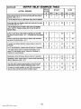
TROUBLESHOOTiNG
GUiDE . . . . . . . . . . . . . . . . . . . ...37
OUTPUT RELAY
EXAMPLES
TABLE .. .... .... ....44
DiP SWiTCH TABLES FOR
WiRELESS
DEViCES . . . . . . . . . . . . . . . . . . . . . . . . . . . . . . . 46
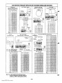
SUMMARY OF CONNECTiONS
Diagram ... ... .. 47
PROGRAMMiNG FORM . . . . . . . . . . . . . . . . . .. Centerfold
–3-
www.PDF-Zoo.com
and Tabi e s
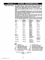
Introduction
System
Zones Supported
state-ofThe Ademco via30 k a microprocessor-based
the-art security control intended for wireless applications.
Supports up to 32 zones, in the following configuration:
2 hard wired EOLR “basic” zones.
Up to 30 expansion zones (wireless and/or additional
wired zones) by using an appropriate RF receiver( 4281
or 5881 type) or wired expansion unit (No. 4219 or
4229). Refer to the Zone Characteristics tabulation on
the next page for detailed zone information.
/Vote: The sirg/e 4281/5881 type RF receiver that the
Adenwo via30 accommodates, features Spatial
Diversity (dual antennas), which virtually eliminates
the possibility of “Nulls” and “Dead Spots” within
the coverage area.
●
●
I
Alarm Output Advisov
I
Relay Outputs
2 or 4 output relays can be added, to perform programmable actions in response to zone activity or manual
entries, by using a No. 4229 Wired Expansion/Relay Unit
(8 wired zones and 2 output relays) or No. 4204 Relay Unit
(4 output relays).
Programming
A No.5137 or 6139 Alpha Console is required
for programming
zones and relay operation, but
it need not remain in the system. These consoles have
digital keypads and 2-line 32 character alphanumeric LCDS
(Liquid Crystal Displays).
Programmed options to establish specific alarm and reporting features are stored in electrically erasable, nonvolatile EEROM memory. This means that the unit can be
reprogrammed many times (unlike units equipped with
PROMS) and that information which has been programmed will not be lost in the event of a complete loss of
power.
In addition, the system can be uploaded, downloaded, or
controlled via a computer and Hayes modem (see REMOTE PROGRAMMING AND CONTROL on page 34).
Remote Consoles
After programming, the system may use one or more
4127, 4137, 5137, 6127 or 6139 Consoles. The 4127,
4137, and 6127 have digital keypads and fixed English
status LCDS.
This system includes an alarm
output
rated at 2 amps.
Throughout
the
manual,
wherever
reference
is
made
to
Alarm
Output
assume
a
Ratings,
they
Note:
fully charged battery is
connected, unless the UL
rating is stated. The battery
is periodically tested automatically (approximately every four
hours), and if it cannot sustain a
load, a low battery message is
displayed and can be reported to
the”central station.
I
When wireless is in use, the system may aLso be armed
and disarmed with a wireless keypad (No. 5727/5827) or
other 5800 RF system units (e.g., Nos. 5801, 5802,
5803).
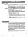
Jser Codes
Up to 3 secondary user codes can be assigned by the system’s Master code.
communication
The system provides communication capability (central
station reporting, etc.) over existing telephone lines.
–4–
www.PDF-Zoo.com
and 5137AD (Addressable) Consoles
may be used, provided they are set to their nonaddressable mode (device ID 31 ...all DIP switch
positions UP).
4137AD
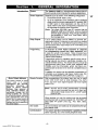
Zone Characterlstlcs
!ones
1-4
not present
!ones
5,6
Wired Programmable
Zones. EOLR supervised,
N.0, or N.C. sensors, 300-500 msec normal response.
!ones
7, 95, 96 Console Panics (Wired & Wireless). 24hr zones, programmable for silent, audible, auxiliary, or fire.
!one
8
Duress (see User’s Manual).
!one
9
Tamper. Reports faults in the expansion units (e.g.,
4219, 4229, 4281), tampers on 5800 system RF units
(5881), and trouble-by-day/alarm-by -night zones. For all
repori formats (except Contact ID, which provides more
explicit reporting) a trouble code is reported when the
system is not armed, and Zone 9 report code is sent for an
alarm.
additional
Mired
Vogrammabie
tones
Up to 8 loops can be added, with a 4219 Wired
Expansion Unit or No. 4229 Wired Expansion/Relay Unit.
Loops are EOLR supervised, for N.O. or N.C. sensors,
300-500 msec normai response, with optionai fast (1O-15
msec) response on ioop A (first expansion zone). Zone
numbers 10-17 should be assigned when using a 4219
or 4229 for zone expansion.
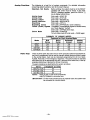
Alireiess
Up to 30 wireiess (RF) zones can be added by
using an Ademco 4281(5700 System) or 5881 (5800
System) Type RF Receiver. Specificaiiy:
Number of Zones
Modei
Zones
4281 L
4281 M15881L
5881M
4281 H/5881 H
up to 4
Up to 8
Upto 16
up to 30
Zone number assignments (which are also transmitter iD
assignments for 5700 RF system transmitters) can be in
the 10-63 range (18-63 when a 4219 or 4229 is aiso
used). A variety of RF system transmitters can be used to
make up the wireiess zones. This includes window/door
units, smoke detectors, PIRs, and panic keys.
Note: For brevity, subsequent references herein to the
RF Receiver will be indicated by “4281/5881” unless a specific model is named.
if (4219/4229) wired exDansion
zones and (4281/5881)
wireless
expansion
zones are ~o be added, they can comprise up to 8
(4219/4229) wired zones, pius wireiess zones up to the number permitted by
the type of 4281/5881 RF receiver used, as long as the tots/ does not exceec
the 30 expansion zones accommodated by the control.
For example: When aii 8 ioopsofa4219 or 4229 are to be used, a 4281H 01
5881H can add oniy 22 zones, so as not to exceed a totai of 30
expansion zones for this controi.
-5-
www.PDF-Zoo.com
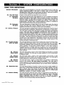
ZONE NPE
DEFINITIONS
General Information
Zone Not Used
Program a zone with this zone type if the zone is not used.
01 - Entry/Exit
Burglary
This zone type provides entry delay whenever the zone is faulted if the control is
armed in the Away or Stay modes. When the panel is armed in the Instant or
Maximum modes, no entry delay is provided. Exit delay begins whenever the
control is armed, regardless of the arming mode selected. These delays are
programmable. This zone type is usually assigned to sensors or contacts on
doors through which primary entry and exit will take place.
03- Perimeter
Burglary
This zone type gives an instant alarm if the zone is faulted when the panel is
armed in the Away, Stay, Instant or Maximum modes. This zone type is usually
assigned to all sensors or contacts on exterior doors and windows.
Interior, Follower
This zone type gives a delayed alarm (using the programmed Entry/Exit time) if
the Entry/Exit zone is faulted first. Otherwise this zone type gives an instant alarm.
This zone type is active when the panel is armed in the Away and Maximum
modes. This zone type is bypassed automatically
when the panel k
armed in the Stay or Instant modes. This zone type is usually assigned to a
zone covering an area such as a foyer, lobby, or hallway through which one must
pass upon entry (After faulting the entry/exit zone to reach the console to disarm
the system.) Since this zone type is designed to provide an instant alarm if the
enty/exit zone is not violated first, it will protect an area in the event an intruder
hides on the premises prior to the system being armed, or gains access to the
premises through an unprotected area.
Trouble by Day/
Alarm by, Night
This zone type will give an instant alarm if faulted when armed in the Away, Stay,
00-
04-
05-
Each zone must be assigned to a zone type, which defines the way in which the
system responds to faults in that zone. In addition, there are three keypad
activated zones (PANIC keys, see note below), and two RF supervisory zones for
the RF Receiver if installed. Zone types are defined below.
Instant or Maximum (night) modes. During the disarmed state (day), the system
will provide a latched trouble sounding from the console (and a central station
-
~,
report, if desired). This zone type is usually assigned to a zone which contains a
foil-protected door or window (such as in a store), or to a zone covering a
“sensitive” area such as a stock room, drug supply room, etc. This zone type can
also be used on a sensor or contact in an area where immediate notification of an
entry is desired.
06- 24-hour
Silent Alarm
This zone type sends a report to the Central Station but provides no console
display or sounding. This zone type is usually assigned to a zone containing an
Emergency button.
07- 24-hour
Audible Alarm
This zone type sends a report to the Central Station, and provides a rapid
beeping sound at the console, and an audible external alarm. This zone type is
usually assigned to a zone that has an Emergency button.
08- 24-hour
Auxiliary Alarm
This zone type sends a report to Central Station and provides a rapid beeping
sound at the console. (No bell output is provided). This zone type is
usually assigned to a zone containing a button for use in personal emergencies,
or to a zone containing monitoring devices such as water sensors, temperature
sensors, etc.
09- Supervised Fire
This zone type provides a fire alarm on short circuit and a trouble condition on
open circuit. The beil output will puise when this zone type is faulted. This zone
type is always active and cannot be bypassed. This zone type can be
assigned to controi panei wired zone 5, any zone in a wired zone
expansion
moduie, or certain wireiess zones.
10- Interior w/Delay
This zone type gives entry/exit delay (using the programmed entry/exit time), if
tripped when the panel is armed in the Away or Maximum modes. This zone
type is bypassed when the panei is armed in the Stay or instant
modes. Delay begins whenever sensors in this zone are vioiated, regardless of
whether or not an entry/exit delay zone was tripped first.
-6–
www.PDF-Zoo.com
.
~
Arm-Stay
20-
21 - Arm-Away
22-
23-
Disarm
No Alarm
Response
This is a special purpose zone type used with 5800 series wireless pushbutton or
contact closure or opening, and which will result in arming the system in the STAY
mode when the zone is activated.
This is a special purpose zone type used with 5800 series wireless pushbutton or
contact closure or opening, and which will result in arming the system in the
AWAY mode when the zone is activated.
This is a special purpose zone type used with 5800 series wireless pushbutton or
contact closure or opening, and which will result in disarming the system when the
zone is activated,
This zone type can be used on a zone when an output relay action is desired, but
with no accompanying alarm (ex. lobby door access).
By using a 4281/5881 RF Receiver and the appropriate 5700/5800 series
transmitters, all of the above zone types are available for the wireless portion of
the system.
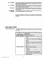
HARD-WIRED
ZONES
Basic Control’s Zones
The Ademco via30 supports 2 hard-wired zones, which are connected as
zones 5 & 6. These zones must be EOLR supervised, and can use N.O. and/or
N.C. sensors.
Zone
Response
Type
Response
Time
I/lax. Zone Resistance
EOLR
Supervised
Any zone response can be assigned to devices on
these zones.
300-500 msec.
300 ohms, excluding EOLR
●
●
●
EOLR Fire Zone 5
●
●
●
●
●
-7–
www.PDF-Zoo.com
Supports both open circuit and closed circuit
devices.
Connect open circuit devices in parallel across
the loop. The 1,000 ohm EOLR must be
connected across the loop wires at the last
device.
Important: If the EOLR is not at the end of the
loop, the zone is not properly supervised. The
system may not respond to an open circuit within
the zone.
Connect closed circuit devices in series with the
loop.
Only zone 5 can be used for fire.
Supporls as many 4-wire smoke detectors as can
be powered.
The zones must be configured for EOLR
supervision.
The detectors must be wired in parallel, with the
EOLR at the last detector for full supervision.
To supervise power, a supewisory module (e.g.,
System Sensor No. BK-A7771 601 EOL Relay
Module) is required.
WIRED
ZONE EXPANSION
No% 4219 and 4229
Expansion Units
If a No. 4219 Wired Expansion Unit, or 4229 Wired Expansion/Relay Unit is used,
8 wired EOLR zones can be added to the basic control’s 2 zones, for a total of 10.
Location
Connections
Supervision
Can be mounted within or outside of the Ademcc
via3fl cabinet (see page 14).
Connects to the control’s remote console terminals fol
signaling.
“ Supervised against removal.
Has tamper protection for security when mounted outside of the cabinet.
. Eight wired expansion loops (designated A to H)
should be assigned zone numbers 10-17, and any 01
all can be programmed individually (infield ‘56).
If RF will be used in addition to one of these units (see
WIRELESS EXPANSION sections), any zone nufiers
in the range of 18-63 (not 10-17) should be chosen for
the RF zones, even if some of the unit’s wired ex
pansion loops are not being used.
For example:
If only four of the wired expansion loops are being
used, a 4281 H or 5881 H RF Receiver could add 26 RF
zones (using any zone numbers in the range of 18-63)
to the system, for a combined total of 30 expansion
zones.
If a 4219 or 4229 is not being used, however, the same
receiver could add 30 RF expansion zones to the system, assigned any zone numbers within a 10-63 range.
The 4219’s or 4229’s DIP switch must be set
[or a device address of “l”, as described in their
instructions (bottom 3 switches to the RIGHT.. .“on”, and
the next switch above to the LEFT.. .“off”).
●
Zone
Information
●
Settings
For additional information, see the instructions that accompany the 4219 and
4229.
www.PDF-Zoo.com
-8-
EXPANSION
— 5700 RF SYSTEM —
In addition to its basic 2 wired zones, the control, in conjunction with a 4281 RF
Receiver, can provide wireless zones [4281 L: up to 4 zones, 4281 M: up to 8,
4281 H (in this application): up to 30]. A wireless keypad (5727) also can be used
with the system.
General
The receiver can be mounted within the control’s cabinet (see page 15) or installed remotely, in its own housing.
The 4281 recognizes alarms, status messages and keypad control messages
from 5700 Series Wkeless Transmitters operating at 345Mhz (315Mhz for Canadian version). These messages are processed and relayed to the control panel
via a 4 wire connection to the control’s remote console terminals. The 4281’s
RED, BLACK, YELLOW, and GREEN wires are connected in parallel with console
wiring.
The 4281 can receive signals from wireless transmitters (listed below) within a
nominal range (installed) of 200 feet.
The 4281’s DIP switch must be set for a device address of “O”, as
described in the 4281’s instructions (all switches to the RIGHT...’’off”).
Each transmitter (except 5701 and 5727) is supervised by a check-in signal that is
sent to the receiver at 70-90 minute intervals. If at least one check-in is not received from each transmitter within a 12 hour period, the “missing” transmitter
number(s) and “CHECK” will be displayed on the console.
Supervision
Each transmitter (including 5701) is also supervised for low battery conditions and
will transmit a low battery signal to the 4281, with the battery having at least 30
days of life remaining. If the 5727 transmits and has a low battery, it also will be indicated (as Zone 00 on a fixed English console).
Note: After a low or dead battery is replaced, activate the transmitter and then
enter the security code + OFF to clear the system’s memory of the “Low
Battery” signal.
The 4281 itself is supervised. If communication with the receiver is interrupted, or
valid RF signals from at least one supervised wireless transmitter are not received
within 12 hours, a tamper report (Zone 9) will be generated.
House Identification
The 4281 responds only to transmitters set to the same House ID (01-31, see the
DIP switch tables on page 46) as programmed in the control (see field *24). This
prevents interference from transmitters in other nearby systems. To make sure
that a House ID is chosen that is not in use nearby, conduct the Sniffer Mode test
described under TESTING THE SYSTEM.
Transmitter
Identification
Each transmitter’s assigned zone number is DIP switch programmable in the unit
as its transmitter ID (except wireless keypads, which are fixed at ID 00). Whenever
a transmission takes place, whether for an alarm, fault, check-in, or low battery, the
ID number is sent along with the message to the 4281 which, in turn, relays this information to the control, which displays the condition and zone number on the
console.
5700 RF System
Installation
Advisories
I
1. If the 4281 Receiver is to be
mounted remotely (not in the
control’s cabinet), place it in
a high, centrally located
area for best reception.
2. Do not locate receiver 01
transmitters
on or neal
metal objects. This will de.
crease range and/or block
transmissions.
3. Before mounting transmit.
ters permanently, conduci
Go/No Go Tests to verif~
adequate signal strength
(see TESTING THE SYS
TEM) and reorient or relo
cate transmitters if neces
sary.
I
WIRELESS TRANSMITTERS for the 4281 are described on page 41.
DIP SWITCH SETTING TABLES are shown on page 46.
Transmitters set for IDs of 48-55 (FIRE) have high signal priority and will
transmit once every 12 seconds while the zone is faulted.
Transmitter iDs of 62 and 63 are unsupervised to allow removal of the 5701
off-premises. Signal priority is higher than burglary.
Transmitters set for IDs of 56-63 will transmit once every 3 seconds while
faulted.
Transmitters set for IDs of 32-47 will have a 3 minute lock-out between
transmissions to conserve battery life (normally PIR units).
Note: To conserve battery life, transmitters protecting frequent/y used doors
and windows should be set for IDs in the 32-47 range.
-9–
www.PDF-Zoo.com
WIRELESS
EXPANSION
General
-5800
RF SYSTEM —
In addition to its basic 2 wired zones, the control, in conjunction with a 5881 RF
Receiver, can provide wireless zones [5881 L: up to 8 zones, 5881 M: up to 16,
5881 H (in this application): up to 30]. wireless keypads (5827) also can be used
with the system.
The receiver can be mounted within the control’s cabinet (see page 15) or installed remotely, in its own housing.
The 5881 recognizes alarms, status messages and keypad control messages
from 5800 Series Wireless Transmitters operating at 345Mhz. These messages
are processed and relayed to the control panel via a 4 wire connection to the control’s remote console terminals. The 5881’s RED, BLACK, YELLOW, and GREEN
wires are connected in parallel with console wiring.
The 5881 can receive signals from wireless transmitters (listed below) within a
nominal range (installed) of 200 feet.
The 5881’s DIP switch must be set for a device address of “O”, as
described in the 5881’s instructions (ail switches to the RIGHT...’’off” ).
Supervision
Each transmitter (except 5802, 5802CP, 5803, and 5827) is supervised by a
check-in signal that is sent to the receiver at 70-90 minute intervals. If at least one
check-in is not received from each transmitter within 12 hours, the “missing”
transmitter number(s) and “CHECK”’ will be displayed on the console. The supervision for a particular transmitter may be turned off by learning it as a “UR”
(unsupenfised RF) type.
Each transmitter is also supervised for low battery conditions and will transmit a
low battery signal to the 5881, with the battery having at least 30 days of life remaining. if the 5802, 5802CP, 5803, or 5827 transmits and has a low battery, it
will also be indicated.
Note: After a low or dead battery is replaced, activate the transmitter and then
enter the security code + OFF to clear the system’s memory of the “Low
Battery” signal.
Some transmitters (e.g. 5802, 5802CP, and 5803) contain long-life but
non-replaceable batteries. At the end of their life, the complete unit must
be replaced [and new identification code(s) learned by the control... see
Transmitter Mentificaticm below].
The 5881 itself is supervised. If communication with the receiver is interrupted, or
valid RF signals from at least one supervised wireiess transmitter are not received
within 12 hours, a tamper report (Zone 9) will be generated.
House
Identification
If a 5827 Wireless Keypad is used with the system, it must have its DIP switch set
to the same House ID (01-31) as programmed in the control for the RF receiver
24) to establish proper communication. D/P switch sef(see programming field ●
ting information for the 5827 is given on page 46.
Transmitter
Identification
Each transmitter input has a different ID (identification) code, part of which ineludes a unique serial number permanently assigned to the device during manufacture. Many transmitters have more than one input, hence ID code (e.g., 5801
has 4,5803 has 3, etc.).
It is not necessary to assign a transmitter’s ID(s) during installation. Instead, the
control must learn or be programmed for each transmitter’s ID code(s) during
programming, in conjunction with assigned zone number(s) and other data.
Whenever a transmission takes place, whether for an alarm, fault, check-in, or low
battery, the ID code is sent as part of the message to the 5881. In turn, the
information is relayed to the control, which displays the condition and associated
zone number on the console.
WIRELESS TRANSMITTERS for the 5881
are described on page 42.
[
–lo–
www.PDF-Zoo.com
Transmitter
System installation
Options
To install the particular transmitters in the system, one of two optional methods
can be used. “Option 1, whose procedure is-described in general below, and in
detail in PROGRAMMING THE SYSTEM on page 21, involves having the system
learn each transmitter to be used in the system. Option 2 (to be available soon),
described below, involves the downloader, where the IDs can be entered
manually at the office and then downloaded to an operating system.
OPTION 1
Learning and Assigning iD Codes at the Controi
Each transmitter sends its unique serial number with each transmission, but since
some devices have more than one sensor point (input), and the sensor point is
part of the ID, each ID must be learned and assigned separately.
As part of the programming of each zone, the device type is entered, and following that, the display of “Learn S/N?” comes up. If the control is to be taught the
IDs now, pressing [1] will get the display “Transmit Now”.
The control program is now at a zone number to be assigned to a given transmitter input (multi-point contact, single-point motion detector, single-point smoke
detector, multi-point emergency transmitter, etc.). A transmitter will either be already installed, or one of a group of transmitters to be installed at a given site. The
corresponding transmitter point (input) is then activated to generate a complete
event transmission (e.g., opening and closing a contact, closing and opening a
contact, pressing and releasing a button, causing alarm and restore, etc.). The resulting transmission will contain an ID code identifying the device by serial number
and its activated point.
If the ID code of this first transmission event has not been previously learned, the
assignment of zone number and ID code (device serial number and sensor point)
is stored in the control memory, Concurrent with this first event, the console emits
a single, short sound to acknowledge this fact and to request a duplicate transmission event to verify the assignment. Upon completion of a second identical
transmission event (within a pre-determined time limit), the control compares this
second (verify) event with the first (learn) event. If the two events match, the control keeps the assignment in EEPROM memory and the console emits a double,
short acknowledge sound.
If the ID of the first transmission event was previously learned, a single, long error
sound is emitted. If the second (verify) transmission event does not match the
first (learn) transmission event, the ID of the first transmission event is erased and
the assignment is discarded.
In this mode, the selected zone number for that transmitter sensor point together
with other system attributes associated with that particular zone are concurrently
assigned to the “learned” ID code.
I
5800 RF System
Installation
Advisories
If the 5881 Receiver is to be
mounted remotely (not in the
control’s cabinet), place it in
a high, centrally located
area for best reception.
Do not locate receiver 01
transmitters
on or neal
metal objects. This will decrease range and/or block
transmissions.
Before mounting transmit.
ters permanently, conducl
Go/No Go Tests to verify
adequate signal strength
(see TESTING THE SYS
TEM) and reorient or relo.
cate transmitters if neces
sary.
OPTION 2
Manuai iD Code Assignment
REMOTE PROGRAMMING AND CONTROL (DOWNLOADING)
section on page 34.
At the downloader computer location, the downloader for the Ademco via30 is
brought up.
The identification code numbers can be entered at the screens where the zone
characteristics and communicator reporting codes are entered. If the 5800 RF
system has been properly selected (RF expander type 5881 ) on a previous
screen, the type of transmitter and identification code (which includes input loop
data) can be entered on the same line as the other items for each zone. The factory pre-recorded serial number is read from the non-removable portion of the
transmitter case in a 7-decimal digit (telephone number) format.
Mark the transmitters to be used in the installation (multi-point contact, singlepoint motion detector, single point smoke detector, multi-point emergency sensor, etc.) and enter their ID codes when programming other data for the system.
When the data that defines the system is downloaded, the identification-codes
will be downloaded also and stored in EEPROM memory.
Supplements
–l1-
www.PDF-Zoo.com
Method
(TO BE AVAILABLE SOON)
RELAY OUTPUTS
Nos. 4204 and 4229
Output Relay Modules
4204
Setup
The Ademco v/a30 can support relay outputs via the use of either a 4204 (4
outputs) or a 4229 (2 outputs). These modules provide form C (normally open
and normally closed) dry contacts on relays that can be programmed to activate or
deactivate to perform some action in response to a predetermined event such as
turning on lights and/or closing a fire door in the event of a fire alarm condition.
There are many different uses for these relays, some of which are suggested in
the table on page 44.
The unit can be located inside the control’s cabinet or remotely (see MOU/VT//VG
THE CONTROL, LOCK, & PC BOARD section and the instructions that accompany the unit).
The 4204 Relay Unit has 4 Form C relays. Each relay can be used independently
for different functions. The following steps should be taken to properly set up the
4204:
1. Connect the 4204 to the control’s remote console terminals
(4-7), using standard 4-conductor twisted cable (for long wiring runs) or the
connector supplied with the 4204 (as shown in the Summary of Connections
diagram).
2. Set the 4204’s DIP switch for a device address of “1” (switch 2
“OFF” and switches 3, 4, 5 “ON”). Switch 1 determines
3.
4.
4229 Setup
the unit’s cover tam-
per response (“ON’” = disabied, “OFF” = enabled).
Note: Some “early” units have only a 4-position DIP switch. Set 1 to “OFF”
and 2, 3, 4 to “ON”.
During programming (summarized here, but see the detaiied procedure
in the PROGRAMMING THE SECURITY CONTROL section):
a. Program a”~ in field ●25.
b. Program fields ’80 (Output Relays) and ●81 (Zone Lists) for the desired
relay responses.
Connect the desired fieid wiring to the unit’s reiay contact terminals.
The 4229 Wired Expansion/Relay Unit has 8 hard-wired zones and 2 Form C relays. Each relay can be used independently for different functions. The foilowing
steps should be taken to properly setup the 4229:
1. Connect the 4229 to the controi’s remote consoie terminais
(4-7), using standard 4-conductor twisted cabie (for long wiring runs) or the
connector suppiied with the 4229 (as shown in the Summary of Connections
diagram).
2. Set the 4229’s DiP switch for a device address of *’1‘“ (switch 2
“OFF” and switches 3, 4, 5 “ON”). Switch 1 determines zone A’s response
time (“ON” = normal response, “OFF”= fast response).
3. During programming (summarized here, but see the detailed procedure
in the PROGRAMMING THE SECUR/TY CONTROL section):
a. Program a”2 in field *25.
b. Program fieids ●8O (Output Relays) and ●81 (Zone Lists) for the desired
reiay responses.
c. In field ●56 (zone programming), assign zone numbers 10-17 to the
4229’s wired expansion zones.
4.
Connect the desired fieid wiring to the unit’s reiay contact terminais.
–12–
www.PDF-Zoo.com
-
Relavs can be used to Derform manv different functions and actions. In this svstern, ~ach relay must be programmed as to how to act (ACTION), when to activ~te
(START), and when to deactivate (STOP). Each of these is summarized briefly
below, but described later in detail in the programming procedure for fields “80
and ’81.
1. ACTION: The “ACTION” of the relay is how the relay will respond when it is
activated by the “START” programming. There are 4 different choices of
actions:
CLOSE for 2 SECONDS and then reset.
CLOSE and remain activated until deactivated by “STOP” programming.
PULSE ON and OFF until deactivated by “STOP programming.
NO RESPONSE is chosen when the relay is not used.
2. START: The “START” programming instructs the relay when and under
what conditions to activate. There are 3 parts to be programmed:
EVENT instructs the relay what condition must occur to the zone(s) programmed into the “ZONE LIST” in order to activate the relay. The
“EVENT” and “ZONE LIST” work together. The 4 different choices for
“EVENT” are listed in the P/?OGRAMfd/NG section for field ’80.
ZONE LIST is a fist of zones selected by the installer in field ●81.When an
event occurs as assigned by “EVENT” on any zone within that list, the
relay will activate as selected in ‘“ACTION”. In this way, many zones can
be assigned very easily to a single event. For example: You may wish
a relay to activate (perhaps to activate a strobe for a visual indication)
whenever any zone in a group of zones is fau/ted.
ZONE TYPE/SYSTEM OPERATION. Instead of using a “ZONE LIST” and
“EVENT”, a specific zone (response) type or system operation action
can be selected to activate the relay.
If a specific “ZONE TYPE” is chosen, any zone of that response type going into alarm, trouble, or fault will cause the relay to activate as selected in “ACTION”. Any zone of that type that restores will
deactivate the relay.
If a “SYSTEM OPERATION’” is chosen, that operation will cause
the relay to activate as selected in “ACTION”.
The different choices for “ZONE TYPE and ‘“SYSTEM OPERATION”
are listed in the PROGRAMMING section for field 480.
3. STOP: The “STOP programming instructs the relay when and under what
conditions to deactivate. The 2 parts to be programmed are:
RESTORE ZONE LIST. If a “RESTORE ZONE LIST” is used, the relay will
Output Relay Advisory
I
deactivate when all the zones in that list restore from a previous fault of
If a reki-y is energized before
alarm condition. This will occur regardless of what is programmed to
a wired smoke detector is
“STAR~ the relay; therefore, a “RESTORE ZONE LIST” would norreset, the re/ay wi// be
mally only be used when a “ZONE LIST’ is used to start the relay.
stopped by the interruption
ZONE TYPE/SYSTEM OPERATION. Instead of using a “RESTORE
of Aux. Power that resets
ZONE LIST”, a specific zone (response) type or system operation acthe smoke detector. If this is
tion can be selected to deactivate the relay.
not desired, the power to
If a specific “ZONE TYPE” is chosen, any zone of that rethe relay unit should be
sponse
type that restores from a previous alarm, trouble, or fault condisupplied from another 12V
tion
will
cause
the relay to deactivate.
power source (e.g., the
If
a
“SYSTEM
OPERATION” is chosen, that operation will cause
same source that is powerthe relay to deactivate.
ing external
equipment
The different choices for “ZONE TYPE” and “SYSTEM OPERATION”
through the relay contacts). I
are listed in the PROGRAMMING section for field ●80.
Relay Basics
●
●
●
●
●
●
●
●
●
-13-
www.PDF-Zoo.com
Mounting the Cabinet
Installing the Lock
(if Used)
m
The Aden?co via30 is supplied with a 12-1/2” (318mm) wide x 14-1/2 (368mm)
high x 3“ (76mm) deep cabinet suitable for use in residential installations.
Mount the control cabinet to a sturdy wail using fasteners or anchors (not
suppiied) in a ciean, dry area which is not readily accessible to the generai public.
4 mounting holes are provided at the back of the cabinet.
Use an Ademco No. N6277 Cam
Lock and No. N6277-1 Push-On Clip
(Retainer Clip).
1. Remove the cabinet cover. /t is
easily removable for servicing
and is easily reinstalled.
2. Remove the lock knockout from
the control cabinet cover. Insert
the key into the lock. Position
the iock in the hole making certain that the iatch wiii make contact with the latch bracket when
the door is closed.
3.
Installing the Control’s
Circuit Board Alone,
or (if used),with a
4219, 4229, or 4204
IMPORTANT!
installing
the
Before
cabinet’s
contents,
be
sure to remove the ap.
propriate
metal cabinei
knockouts.
DO NOT ATTEMPT TO RE.
MOVE THE KNOCKOUTS AF.
TER THE CiRCUiT BOARD HAS
BEEN INSTALLED.
Whiie holding the lock steady,
insert the retainer clip into the
retainer slots. Position ciip as iliustrated to facilitate easy rernoval.
\
RmAINER CLIrJ
,wEPosmoN,
[
1,
/0,
LOCKED
RflAINER
RSAINER
sLOTS
CLIP
i 1
i ,, m
* ..:
‘--’
\ UNLOCKED
+
(~
CAOINET DCOR BOITOM
\
\
4219,+
4229,or
4204
/q
~p
COVER TAMPER
JUMPER
–14-
www.PDF-Zoo.com
,
Control’s Circuit Board
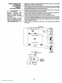
1. Hang two /ong mounting ciips (provided) on the raised cabinet tabs (see Detaii B below).
2. insert the top of the circuit board into the siots at the top of the cabinet. Make
sure that the hoard rests on the correct row (see Detaii A ).
3. Swing the base of the board into the mounting clips and secure the board to
the cabinet with the accompanying screws (see Detail B).
4219, 4229 or 4204
1. Insert seif-tapping screws (provided) in two adjacent raised cabinet tabs.
Leave the heads projecting 1/8”.
2. Hang the unit on the screw heads via two of the slotted hoies at the rear of its
housing, as shown.
3. The 4219’s or 4229’s cover can be ieft off if the cover tamper jumper is placed
in its upper (not tampered) position (see Detaii C). The tampered cover is
necessary for installations outside of the control’s cabinet. ”
I
~
~
Installing Control and
RF Receiver
Circuit Boards
Together,
in the Same Cabinet
1. Hang two short (black) mounting clips (provided with receiver) on the raised
z.
3.
IMPORTANT!
Before
the
Installing
contents,
be
cabinet’s
sure to remove the appropriate
metal cabinet
knockouts.
DO NOT ATTEMPT TO REMOVE THE KNOCKOUTS AFTER THE CIRCUIT BOARDS
HAVE BEEN INSTALLED.
4.
~
“
6.
7.
cWlnet tabs, as shown in Detail B below.
Insert the top of the receiver board (removed from its own case as described
in its instructions) into the slots at the top of the cabinet (see Detail A). Make
sure that the board rests on the correct row of tabs.
Swing the base of the board into the mounting clips and secure it to the cabinet with the accompanying screws (see Detail B).
Insert the top of the control’s board into the slot in the clips and position two
/ong (red) clips at the lower edge of the board (see Detail C).
Swing this board into place and secure it with two additional screws.
Insert grounding lugs (supplied with the receiver) through the top of the cabinet into the /e/t-hand terminals of the antenna blocks (at the upper edge of
the receiver board) and secure them to the cabinet top with the screws provided, as shown in Detail D.
Insert the receivet’s antennas into the block’s tight-handterminals and tighten
the screws.
HOLES FOR ANTENNAS
~AND
L
GROUNDING
LUGs
~.
‘OARDsuppORT’NGsLOTs
RECEIVER
CIRCUIT
BOARD
CIRCUIT
SOARO
~
CABINET
-
@
DETAIL A
SIDE VIEW OF
BOARO SUPPORTING SLOTS
SHORT MOUNTING
CLIPS
CONTROL
CIRCUIT
BDARD
LONG MOUNTINO
OETAIL ❑
SIDE VIEW DF
SHORT MOUNTING CLIPS
CLIPS
SCREW
~
ANTENNA
P
GROUNDING
LUG
$/!’,’ ,; ,,!
o
,,
,,’
DETAIL D
ANTENNA AND
GROUNDING LUG
INSTALLATION
RCVR BOARD
d!ii!!!ii!!
CABINET
–15–
www.PDF-Zoo.com
DETAIL C
SIOE VIEW OF
LONG MOUNTING CLIPS
(See Summary of ConnectIons Diagram on Page 47)
IMPORTANT:
Grounding the System
Terminals and
Connections
Do not connect the battery, or plug In the AC transformer,
until all other wiring connections have been completed.
Terminal 21 is the earth ground connection point. In order for the protective
devices in this product to be effective, the designated terminal must be
terminated in a good earth ground. The following are examples of good eatth
grounds available at most installations:
Metal cold water pipe: Use a non-corrosive metal strap firmly secured to the
pipe to which the lead is electrically connected and secured.
AC power outlet ground: Available from 3-prong, 120 VAC power outlets
only. To test the integrity of the ground terminal, use a 3-wire circuit tester with
neon lamp indicators, such as the UL Listed Ideal Model 61-035, or equivalent,
available at most electrical supply stores.
1 & 2:
3:
4:
5:
AC Input (16.5VAC, 25VA) from No. 1321/TF2 plug-in transformer
(in U.S.A.).
Note: For Canadian installations, a No. 1321CN transformer must be
used.
Alarm relay output(+), 12VDC, 2.OA maximum
(600mA max Alarm plus Aux Power for UL usage).
Alarm Output/Auxiliary Power/Wired Fire/Console(s)/ Optional 4281,5881,
4219, 4229, or 4204 (BLACK lead). Ground (-) Returnt.
Auxiliary/Wired Fire/Console(s)/Optional 4281, 5881, 4219, 4229, or 4204
(RED lead) Power:
+12VDC at 500mA max ~.
6:
Data In from Console(s) /Optional 4281, 5881, 4219, 4229, or 4204
(GREEN)t.
7:
Data Out to Console(s)/Optional 4281, 5881, 4219, 4229, or 4204
(YELLOW)t.
8–1 3: not used
14: Zone 5. (When Zones 5 and/or 6 are used, a 1,000 Ohm EOLR should be
wired between the farthest sensor connected to the zone terminal and the
low side of the zone.)
15: Zones 5 and 6 Return.
16: Zone6
17: Handset (TIP).
18: Handset (RING).
19: Incoming Phone Line (TIP).
20:
Incoming Phone Line (RING).
21: EARTH GROUND (a proper earth ground must be provided to protect the
system from lightning and electrostatic discharge damage).
Warning: To prevent the risk of electrical shock, disconnect the telephone line
at the Te/cojack before servicing the unit.
RED LEAD: Battery (+). When AC is present, 13.8VDC is being developed to
recharge a gel lead acid battery and when AC is absent, 12VDC current is
drawn from the battery. Battery lead reversal will blow the battery fuse.
BLACK LEAD:
Battery (-).
t
Up to 4 consoles may be used (check total auxiliary current, per SPEC/F/CAVONS). Consoles need not necessarily be on individual home runs, but
no more than 220 of #22 wire or 550’ of #18 wire should be used for each
run.
Addressable consoles (e.g., 4137AD and 5137AD) may be used, if they
are set to their non-addressable mode (device ID 31...all DIP switch positions UP).
–16-
www.PDF-Zoo.com
Power-up Procedure
1. Make sure that the total current to be drawn from the Alarm Output terminals
(3 & 4) and Auxiliary Power Output terminals (4 &5) does not exceed the
values indicated in the SPEC/F/CAT/ONS section and on the SUMMARY OF
CONNECTIONS diagram.
2. Wire the transformer to the panel (before connecting the battery) as shown
on the SUMMARY OF CONNECTIONS diagram. Do not plug in at this
time.
3. Connect all ioops, devices, consoles, etc. to the panel.
4.
5.
Piug the transformer into a 24 hour, uninterrupted AC outlet. After some initial displays (see page 22) and approximately one minute, the green POWER
or READY LED on the consoie(s) should be lit and the consoles should dis-
play “READV (Fixed Word consoles) or “DiSARMED READY TO ARM”
(Alpha consoles).
Connect the battery as shown in the SUMMARY OF CONNECTIONS
diagram.
-17-
www.PDF-Zoo.com
SECURITY CODES
Master Code
User Codes
The installer programs the 4-digit Master Code initially as part of the programming
procedure (see W?OGRAIMWVG THE SYSTEM). The factory default Master code
is “4111”.
The Master code can permit re-entry into the programming mode and also, in
normal operation mode, is used to enter the user codes, which also allow access
to the normal functions of the system.
See the Pl?OGRA/14M//VG section for information on exiting the programming
mode via fields ’98 or ’99.
In normal operation mode, the Master security code can be used to assign up to
three secondary security codes. It can also be used to remove secondary codes
from the system (individually).
To assign (or change) a Secondary security code, enter:
Master Code + [CODE key]+ User # (2 or 3 or 4) + desired Secondary Code
The system will emit a single beep when each secondary code has been successfully entered.
To delete a Secondary security code, enter:
Master Code + [CODE key]+ User # (2 or 3 or 4)
Notes:
s All Master and Secondary security codes permit access to the system for arming, disarming, etc.
If a secondary code is inadvertently repeated for different users, or one user’s
code is another’s duress code (4th digit increased by 1), the lower user number
will take priority.
Opening and closing reports are sent for the Master code as No. 1. User codes
are sent as Nos. 2, 3, and 4 respectively.
●
●
KEYPAD
FUNCTIONS
General Information
Note that if QUICK ARM is enabled (field ’21), the [#] key can be pressed instead
of entering the security code, for any of the arming procedures (Away, Stay, instant, Maximum, etc.).The security code is a/ways required, however, when disarming the system.
The keypad allows the user to arm and disarm the system, and perform other system functions, such as bypassing zones, and display zone descriptors. Zone and
system conditions (alarm, trouble, bypass) are displayed in the Display Window.
When an alarm occurs, console sounding and external sounding will occur, and
the zone(s) in alarm will be displayed on the console. Pressing any key will silence
the console sounder for 10 seconds. Disarming the system will silence both console and external sounders. When the system is disarmed, any zones that were
in an alarm condition during the armed period will be displayed (memory of alarm).
To clear this display, simply repeat the disarm sequence (enter the security code
and press the OFF key) twice.
The consoles also feature chime annunciation, and 3 panic key pairs (for silent,
audible, fire or personal emergency alarms) which can notify the central station of
an alarm condition, if that service is connected.
–18–
www.PDF-Zoo.com
W
Arming Functions
The following is a brief list of system commands. For detailed information
concerning system functions, refer to the User’s Manual.
Before arming, the system must be in the READY
Disarmed, Not Ready
condition (all zones must be intact). If the “NOT
READY” message appears, press the READY ~]
key to display faulted zones.
Enter code + AWAY [2].
Arming Away
Enter code + STAY [3].
Arming Stay
Enter code + INSTANT [7].
Arming Instant
Enter code + MAXIMUM [4].
Arming Maximum
Enter code + OFF [1].
Disarming
Enter code + BYPASS [6]+ zone number(s).
Bypassing Zones
Forced (Quick) Bypass (If enab/ed) To automatically bypass all faulted zones,
use “Quick Bypass” method:
Enter code + BYPASS (then stop).
Enter code + CHIME 191.
Chime Mode
To turn chime mode dff; enter code+ CHIME again.
Mode
AWAY
STAY
INSTANT
MAXIMUM
Panic Keys
SUMMARY OF ARMING MODES
Features for Each Arming Mode
Entry
Perimeter
Interior
Exit
Delay
Armed
Armed
Delay
Yes
Yes
Yes
Yes
Yes
No
Yes
Yes
Yes
No
No
Yes
No
Yes
Yes
Yes
There are three panic key pairs and (on some consoles) lettered keys(shown below) that, if programmed, can be used to manually initiate alarms and send a report
to the central station. Each can be individually programmed for 24 Hour Silent,
Audible, Personal or Fire Emergency responses. The panic function is activated
when both keys of the appropriate key pair is pressed at the same time, or the appropriate lettered key is pressed for at least 2 seconds.
The panic functions are identified by the system as follows:
n
Notes:
●
●
Keys [A], [B], [C] are not on all consoles.
Key [D], if present, is not active here.
IMPORTANT:
For the Panic functions to be of practical value, the system must
be connected to a central station.
-19–
www.PDF-Zoo.com
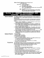
TROUBLE
CONDITIONS
General Information
The word “CHECK on the Console’s display, accompanied by a rapid “beeping”
at the Console, indicates that there is a trouble condition in the system. The audible warning sound can be silenced by pressing any key. Instruct users to call for
service immediately upon seeing any of the following messages.
“Check” and
“Battery” Dispiays
Q A dlspiay of “CHECK” and one or more zone numbers indicates that
a problem exists with the displayed zone(s) and requires attention.
When the problem has been corrected, the display can be cleared by entering
the OFF sequence (code plus OFF key) twice.
c if there are wireless sensors in the system, the CHECK condition may
also be caused by some change in the environment that prevents the receiver
from hearing a particular sensor.
A dispiay of “BAT’” with no zone number indicates that the system’s
main standby battery is weak.
A display of “BAT” with a zone number and a once per minute
“beeping” at the consoie indicates that a low battery condition exists in
the wireless sensor displayed (zone “00” indicates a wireless keypad). If the
battery is not replaced within 30 days, a CHECK display may occur.
Not e: Some wireless sensors contain a non-replaceable long-life battery
which requires replacement of the entire unit at the end of battery life
(e.g., Nos. 5802, 5802CP, 5803).
If there is no console display at all, and the POWER indicator (if
present) is not lit, operating power for the system has stopped and the system is inoperative.
●
●
Power Faiiure
●
●
Other Dispiays
{Fixed Word Consoies)
if the message “AC LOSS” or “NO AC” is displayed, and the
POWER Indicator (if present) Is off, the console is operating on battery
power only.
di
If this remains displayed for more than 1 minute, the system is disabled.
CC
The system is in communication with the central station for change of function or status verification.
FC
OC
A communication failure has occurred.
The console is not receiving signals from the control panel and sees an
open circuit.
–20–
www.PDF-Zoo.com
*
General Information
Installer options are stored in non-removable, electrically erasable, non-volatile
EEROM memory. These options must be programmed for the particular installation to establish its specific alarm and reporting features.
Note: It is possible to program the system at any time, even at the installer’s
premises prior to the actual installation. Simply apply power temporarily to
the control and then program the unit as desired.
THE SECURITY CONTROL IS PROGRAMMED VIA A 5137 OR 6139
CONSOLE (which need not necessarily remain in the system after programming).
Note: A 5137AD (Addressable) Console may be used, provided it is set to its
non-addressable mode (device ID 31. ..all DIP switch positions UP).
}
The initial sequence of entries should follow the order on the programming
sheet.
Certain programming fie/ds, such as those used to select the expansion devices
25) must be programmed before expansion zones can be pro(fields ●22 and ●
grammed. If an expansion unit type is changed, the expansion zones should be
reprogrammed.
When programming, the field number will be displayed on the LCD display; also,
each entry is displayed as it is keyed in. After programming, values that have been
entered in each field can be reviewed and, if necessary, modified.
When programming from the console, note the following:
1. Enter the Programming mode by simultaneously depressing the ~] and [#]
keys within 50 seconds after power is applied to the Control, or
subsequently by keying the code 4 + 1 + 1 + 1 followed by depression of
CODE + O keys. If a different Master code is subsequently programmed,
use it instead of 4111 to gain access to the Programming mode. H the F?ogramming mode was exited previous/y using a *98, it wi// prevent entry info
the Programming mode by the use of the Master Code+ CODE+ O.
2. Immediately following entry into the program mode, field ●2Owill be displayed.
Following the above display, the system is ready to accept entries for field
’20.
3.
To program a data field, key ~] plus Field No. (for example, *21), then make
the required entry.
Some entries require sequential pressings of ~] to actually enter the data. This is
56, ’80, and ●81 and the prompts will inditrue in the Zone and Relay fields ●
cate this. Entry of 1#1will generally backup one entry position for review.
4.
5.
To simply review a data field, key [#] plus Field No.. Data will either be automatically sequentially displayed or can be displayed by successively pressing [#]. No changes will be accepted in this mode.
When a data field has been completely programmed, the console will normally
“beep” three times and then automatically proceed to, and display, the next
data field number to be programmed (if not, key ~] plus the Field No. of the
next field to be programmed).
6. If the number of digits that you enter in the data field is less than the maximum
permitted (for example, phone number), then the console will display the last
data entered. To proceed, the next data field number to be programmed
must then be entered (for example, *42).
7. If a field is improperly entered, the console will display EE. Simply re-enter [*]
or [#] plus the field number.
-21-
www.PDF-Zoo.com
Summary of
Programming
Commands
FUNCTION
ENTER PROGRAMMING MODE
EXIT PROGRAMMiNG MODE
ADVANCE TO FIELD
PROGRAM FIELD
ERASE FIELDS
READ FIELD
Special Messages
www.PDF-Zoo.com
1. POWER UP, then depress
[X] and [#] both at once, within
50sec of powering up.
OR
2. Initially, key: 4 +1 + 1 +1
plus CODE key + O.
OR
3. If different Master Code is programmed,
key :
MASTER CODE + CODE KEY + O
(if ●98 was used to exit previously,
method 1 above must be used to enter
the program mode again)
99 allows re-entry to programming mode
via type 2 or 3 entry method above.
* 98 inhibits re-entw to Droarammincl
mode via type’2 oi3 e}try metfiod.
[~] + Field No. (e.g., 21, 38, 56, etc.)
●
[x] + Field No., followed by data entries.
Some fields require sequential pressings of
[+$]to enter data (e.g., fields 56, 80,81~
[X] + Field No. + [X] (only applies to
fields 40 thru 44 and 94).
[#] + Field No. Data will either be
automatically sequentially displayed or can
be displayed by successively pressing [#].
OC = OPEN CIRCUIT (no communication between Console and Control).
EE = ERROR (program entry mistake). Re-enter the field number or data).
After powerina UD, AC. dl (disabled) or Svstem Busv and NOT READY will
be displayed ~fie~ approximately 4 seconds: This will re~ert to READY in appx. 1
minute, which allows PIRS, etc. to stabilize. To bypass this delay, press: [#]+ [0].
If E4 or E8 appears, more zones than the expansion units can handle have been
programmed. Correct the program and then completely de-power and re-power
the control to clear this indication and remove the disable indication.
-22-
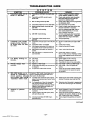
PROGRAMMING
ITHECENTERFOLD
DATA FIELDS
PROGRAMMING FORM CAN BE USED TO RECORD THE DATA FOR THIS INSTALLATION1
SYSTEM ARMING
(’20-’25)
*2O
*21
“22
*23
*24
*25
ZONE SOUNDSAND
TIMING
(28-38)
*28
*29
*3O
*38
DIALER
PROGRAMMING
●4O
(40-50)
MASTER CODE
Enter 4 digits, O-9 (entry of all 4 is mandatory).
Use of a “9” in the last position inhibits the Ambush feature.
QUICK ARM ENABLE
If enabled, [#] key can be used instead of security code when arming the
system.
Enter Ofor disabled or 1 for enabled.
RF SYSTEM TYPE
Select the RF system (receiver) type being used.
O= none; 1 = 5700 (4281); 2 = 5800 (5881)
FORCED BYPASS FUNCTION
All zones that are bypassed by this function will be displayed after the
bypass is initiated.
O= No forced bypass.
1 = Allows automatic bypass of all open zones.
RF RECEIVER HOUSE ID CODE
MUST enter for 5700 system’s 4281 type receiver, or 5800 system’s
5827 keypad.
Enter 01-31 House ID.
WIRED EXPANSION/OUTPUT
RELAY USED
Select expansion/relay unit being used.
O = none; 1 = 4219; 2 = 4229; 3 = 4204
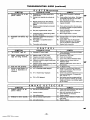
SINGLE ALARM SOUNDING PER ZONE (per armed period)
Enter Ofor no or 1 for yes
FIRE SOUNDER TIMEOUT DISABLE
Enter Oto enable the sounder timeout for fire or 1 to disable it.
ALARM BELL TIMEOUT
External sounder will shut off after time allotted. Enter 1 digit.
2 = 8 minutes
O= No timeout
1 = 4 minutes
3 = 12 minutes
ENTRY DELAY
System will wait the time allotted before sounding alarm upon entering.
(EXIT delay = Entry delay plus 15 seconds)
2 = 30 seconds
O= Oseconds
1 = 20 seconds
3 = 45 seconds
PABX ACCESS CODE
Enter 4 digits, O-9, for each PABX digit needed to access an outside line.
To skip this field, enter ●. If is entered, no PABX number will be dialed
and nothing will appear in this field. End field by entering ●41 if not filled.
To clear entries from field, press “40’.
PRIMARY PHONE No.
Enter up to 12 digits, O-9. Do not fill unused spaces. End field by
entering ●42 if not filled. To clear entries from field, press *41*.
●
●41
Note: Back-up reporling (8 calls are made to the secondary phone
number if no kiss-off is received after 8 attempts to the primary number) is
automatic only if there is a secondary phone number.
*42
SECONDARY
PHONE
No.
See field ’41 entry info. and Note. End field by entering ●43 if not filled.
To clear entries from field, press ●42*.
*43
SUBSCRIBER
ACCOUNT. NO.
Enter digits O-9; #+1 l=B; #+12=C; #+13=D; #+14=E; or #+15=F.
Enter as the fourth digit if a 3 digit acct no. (for 3+1 dialer reporting format) is used. Enter O as the first digit of a 4-digit acct no. for nos. 00000999. End field by pressing (and press next field) if only 3 digits are
used. To clear entries from field, press *43*.
●
●
–23-
www.PDF-Zoo.com
*45
*46
PHONE SYSTEM SELECT
Enter 1 digit.
If Central Station Rcvr is not on WATS line:
O= Pulse Dial 1 = Tone Dial
If Central Station Rcvr /s on WATS line:
2 = Pulse Dial 3 = Tone Dial
REPORT
Detenine
FORMAT
which format is to be used to report to the central station.
Enterl digit.
O= 3+1; 4+1 ADEMCO US Standard
1 = 3+1; 4+1 Radionics Standard
2 = 4+2 ADEMCO Lo Speed Standard
3 = 4+2 Radionics Standard
6 = 4+2 ADEMCO Express
7 = ADEMCO Contact ID Reporting
8 = 3+1; 4+1 ADEMCO Lo Speed Expanded
9 = 3+1; 4+1 Radionics Expanded
(Enter as the 4th digit of ●43, if 3+1 dialer reporting is to be used.)
●
~ For explanation of these formats, seepage 33. ~
Note:
*47
*48
*49
The maximum number of communicator reports during one
armed period is 10.
SPLIT/DUAL
REPORTING
Enter Oto disable (Backup report only)
TO SECONDARY
TO PRIMARY
1=
Alarms, Restore, Cancel
Others
2=
Open/Close, Test
All except Open/Close, Test
All
Alarms, Restore, Cancel
3=
All
4=
All except Open/Close, Test
All
All
5=
15 SECOND DIALER DELAY (BURGLARY)
Allows time for subscriber to avoid a false alarm transmission.
Enter Ofor no or 1 for yes
PERIODIC TEST MESSAGE
Select the desired test report interval.
O = none; 1 = 24 hours; 2 = weekly
Test Report Code entered in field ’64 is sent.
’50
SESCOA/RADIONICS
SELECT
O= Radionics (O-9, B-F reporting)
1 = SESCOA (O-9only reporting)
*51
CONFIRMATION OF ARMING DING
Enter Ofor no or 1 for yes.
If selected, ding is external sounder only and will occur at time of kissoff of
closing report. If closing report is not programmed, ding will occur at end
of exit time.
-24-
www.PDF-Zoo.com
w
*56
ZONE ASSIGNMENT/ALARM
REPORT CODES
(and RF Input ID Learning for 5800 System)
REFER TO THEZONEASSIGNMENT TABLE FOR THIS FIELD I
N THE PROGRAMMING FORM
(See Centerfold)
This field is used to program zone numbers, zone types, alarm and report
codes, and to identify the type of loop input device. This field can also be
used for “learning’” 5800 series transmitter ID codes and for entering alpha descriptors for zones.
Zone Number (Zn)
Upon entering field ’56, enter the zone number that you wish to program
(or [0][0] to leave zone programming).
Press [’]. A summary display will come up, showing the status of that
zone’s program.
If it is programmed satisfactorily, press [#] to back up one step and enter
another zone number, if desired.
If the zone is not programmed, or you want to change it, press [*]. A
prompt for Zone Type will appear.
Zone Type (ZT)
Enter the zone type code (or change it, if necessary). Default values for
zones 05 to 07 are:
~
When the display shows the zone type you want, press [’] to advance
to...
Report Code (RC)
The report code consists of 2 hexadecimal digits, each in turn consisting
of 2 numerical digits. For example, for a report code of “3C”, enter [0][3]
for “3” and [1][2] for “C”. Enter the numbers and press [*] to advance to...
Input Device (In)
For the hard wired zones of the Ademco via30 (HW), the auxiliary wired
expansion zones on a 4219 or 4229 (AW), and the zones for a 5700 system’s transmitters (RF), the Input Device types are automatically displayed
(Panic, Duress, and Tamper inputs are not applicable). For a 5800 system’s transmitters, “RP is initially displayed, but should be changed to
“UR” (Unsupervised RF, enter 4) for units that can be carried offpremises, or to “BR” (Button type RF, enter 5) for small transmitters that
cannot be supervised. Check the instructions that come with the transmitter for the proper input. When all is okay, press ~] to advance to...
Learned RF Input (L)
Note:
Where a “Yes-No” is asked by the console, pressing the ~] or
[0] for No is equivalent.
Applicable to a 5800 system only
This request will be to learn the transmitter input’s ID code. (The ID codes
can be learned here or via field *83.)
If “yes” is selected, open and close (or close and open), or press and release the particular input to the transmitter twice. After the first time, a
single short beep will occur. After the second time, two short beeps will
mean that the control has accepted that transmitter into the system. Because of the characteristics of the receiver, allow about 8 seconds between transmissions from button units. If a long beep occurs, it means
that the particular transmitter input has previously been registered in the
system.
Mark the zone number on the transmitter.
If all is okay, press ~].
www.PDF-Zoo.com
–25-
Custom Alpha Editing
For all zone types, the next request is to enter alpha descriptors for the
zones. The entry may be done now or may be done at a later time via field
●82.
~ See the ALPHA DESCRIPTION ENTRIES section on page 30. ~
When all entries to be made for the zone at this time are complete, the next zone
number can be entered for programming, or zone programming can be ended by
entering [0][0] as the next “zone number”.
Notes:
. When using a 5801, the Function “4” button should always be used and
learned by the system.
. M t7e/d ●56, at the summary line for each zone, the entered values can be
checked. If it is desired to change anything, press [#] to move to the previous
entry. Press [#] a number of times to move to earlier entries. Press ~] to move
to later entries again.
. Zone entries can be reviewed by pressing [#][5][6]. Changes cannot be made
here, so this is safer for review. Enter the first zone number to be viewed and
press [#]. To view each zone, press [#] and the zone number will advance to
the next programmed zone. When the end of the list is reached, press [0][0] to
exit. This method of exiting may also be done at any time during the review.
To either temporafi/y or permanent/y remove a zone from the system, go into
programming mode and press ~][5][6]. Enter the zone number and press ~]. At
the Zone Type prompt, enter [0][0] and [*]. This sets the type of the zone to
Not Used. The next prompt will be “Delete Zone?’. “Yes” will permanently remove the zone from the system while “No” will disable it but retain all data except the original zone type. You can then go back to this zone later and put back
an active Zone Type to re-enable it.
An /0 code that has been /earned for a 5800 system wi// not be deleted if the
zone is disabled as described above. If only the physics/transmitter is to be removed or changed (i.e., its ID code deleted), it can be done in field *56 or ●83.
In programming mode, press [“][5][6], enter the zone number, and press ~]
multiple times until the cursor is under the Learned RF Input (L) position. This is
the specific loop or button on the transmitter that has been learned for that
zone. If a [0] is entered at Ibis point, a prompt “De!ete S/N?” will appear. If “Yes”
is entered, this specific ID code will be deleted from the system.
●
✎
–26–
www.PDF-Zoo.com
(continued on page
27)
~
TO PROGRAM SYSTEM
STATUS & RESTORE
REPORT CODES
(“60-”75)
SYSTEM STATUS
REPORT CODES
(*60-*68)
With a 3+1 or 4+1 Standard Format: Enter a code in the first box: 1-9, 0, B,
C, D, E, or F. Enter “#+1 O“ for O, “#+11“ for B, “#+12” for C, “#+1 3“ for D, “#+14”
for E, “#+15“ for F.
A “O (not “#+1O) in the first box will disable a report.
A “0” (not “#+1 O) in the second box will result in automatic advance to the
next field when programming.
With an Expanded or 4+2 Format: Enter codes in both boxes (1st and 2nd
digits) for 1-9,0, or B-F, as described above.
A “O” (not “#+1 O) in the second box will eliminate the expanded message for
that report.
A “O (not “#+1O“) in both boxes will disable the report.
With Ademco Contact ID Reporting: Enter any digit (other than “O) in the
tirst box, to enable zone to report This is an “enabling” code only and is
disregarded in the actual reporting to the central office. Entries in the second
boxes will be ignored.
A “O” (not “#+10“) in the first box will disable the report.
See examples on programming form.
TROUBLE
REPORT CODE
*6O
See box above.
*61
BYPASS REPORT CODE
See box above.
*62
●63
*64
*65
●66
*67
*68
RESTORE
REPORT CODES
(“69-”7!5)
*69
*7O
●7I
*72
*73
●74
“75
(continued from page 26)
www.PDF-Zoo.com
~
AC LOSS REPORT CODE
See box above.
LOW BAT REPORT CODE
See box above.
TEST REPORT CODE
See box above.
OPEN REPORT CODE
See box above.
2nd digit = User #, if expanded or 4+2 reporting is selected.
CLOSE REPORT CODE
See box above.
2nd digit = User #, if expanded or 4+2 reporting is selected.
Report also sent for Arming STAY, if contact ID format is used.
RF XMTR. LOW BATTERY REPORT CODE
See box above.
CANCEL REPORT CODE
See box above.
GROUP RESTORES FOR TROUBLE, RF LOW BATTERY,
BYPASS
Enter Ofor no (report for each restore)
or 1 for yes (report after all zones restored).
Note: “1”not applicable to Contact ID reporting.
ALARM RESTORE REPORT CODE, 1ST DIGIT
2nd digit is automatically sent as the 2nd digit of the zone alarm report
56, if expanded or 4+2 reporting is selected.
code programmed in field ●
TROUBLE RESTORE REPORT CODE
See box above. Trouble restore is reported only if all troubles in the
system are restored, if field ●69 is enabled.
BYPASS RESTORE REPORT CODE
See box above.
AC RESTORE REPORT CODE
See box above.
LOW BAT RESTORE REPORT CODE
See box above.
RF XMTR, LOW BATTERY RESTORE CODE
See box above.
-27–
-------9UTPUT
--. . ..
HELAY3
---AND
---
-Uu
-------UUIPUI
--.
HELAYS
..4.
Applicable only if fieid *25 is programmed for a 4229 or 4204... otherwise
skip this field.
REFER TO THE OUTPUT RELAY TABLE FOR THIS FIELD
IN THE PROGRAMMING FORM.
ZONE LISTS
(’80, *81)
Output Relay Displays
*
Upon entering field ’80, this screen will appear. Enter the Relay Number 01 or 02
for a 4229, or 01, 02, 03, or 04 for a 4204 (or 00 to end these entries). Press the
~] key to advance.
The data is keyed in and entered for this and the following screens by pressing ~]. To
back up to check an entry, press [#] for each position. Press [*] to go forward again.
This screen displays a summary of the current relay START programming (for this
example, relay 02 has been selected). Press the [*] key to advance.
This screen displays a summary of the current relay STOP programming. Press
the ~] key to advance.
I
02 Relay Action
No Response
O
I
Action (A): Enter the desired relay action. Press the ~] key to advance.
o = Not Used
2 = Close and Stay Closed
(1 see).On and Off
3 = ContinualPulses
1 = Close for 2 seconds
Event (EV): Enter the event to START the relay. Press the ~] key to advance.
2 = Fault
o = Not used
m
1
❑
Alarm
3 = Trouble
Zone List (ZL): if a zone list will be used to START the relay action, enter the
zone list number (to be programmed in field *8 I ): 1, 2, or 3. If not used, enter O.
Press the [*] key to advance.
Type/System Operation (ZT): If a zone type or system operation will
be used to START the relay action, enter the appropriate two digit code. If not,
enter 00. Press the [*] key to advance.
Zone
Zone Disabled 00
CHOICES FOR ZONE TYPES
00= No Response (Not Used)
08 =24 HrAux
05= Trouble Day/Alarm Night
01 = Entry/Exit
09= Fire
06= 24 Hr Silent
03 = Perimeter
10 = Interior w/Delay
04= Interior Follower
07= 24 Hr Audible
CHOICES FOR SYSTEM OPERATION
38= Chime
20= Arming-Stay
33= Any Burglary Alarm
39= Any Fire Alarm
21 = Arming–Away
34. Code+ #+7 Key Entry
40= Bypassing
22= Disarming (Code + OFF) 35. Code+ # + 8 Key Entry
41 = AC Power Failure
36= At Bell Timeout**
31 = End of Exit Time
42= System Battery Low
32= Start of Entry Time
37= 2 times Bell Timeout**
●*Or at Disarming, whichever occurs earlier.
Restore Of Zone List (ZL): If a zone list will be used to STOP the relay action, enter the zone list number (to be programmed in field ’81): 1, 2, or 3. If not
used, enter O. Press the [*] key to advance.
Ez-Hl
02 Stop: Zn Typ
Zone Disabled 00
Zone Type/System Operation (ZT): If a zone type or system operation will
be used to STOP the relay action, enter the appropriate two digit code (see the
“ZT” choices listed above). If not, enter 00. Press the [*] key to advance.
This screen again displays a summary of the current relay START programming .
Press the [*] key to advance.
Em
E511
This screen again displays a summary of the current relay STOP programming.
Press the ~] key to return again to the first screen so that the next relay number to
be programmed can be entered, or enter [0][0] to end relay programming.
Note:
J.
Previous/y entered data can be reviewed by pressing [#] [8] [0]. After the
relay number is chosen, press [#] to go to the next screens. This is a review mode only, and data cannot be changed.
-28–
www.PDF-Zoo.com
Example of
Output Relay
Programming
Let us light an Indicator when any one of 3 specific zones are
faulted or when any 24 hour aux. zone Is disturbed. We want to
turn off the indicator manually without affecting the arming status
of the system.
In field ●8O we choose Output Relay 01 and program the Action (A) to be “2”
(Close and stay closed). The Event we are looking for to starlthe relay action is a
fault, so we will program “2” in (EV). We will use Zone List 1 for the 3 specific
zones, so will program”1 win (ZL), (and will program these 3 zones in field ●81’s
Zone List 1).
The second condition for turning on the indicator is triggering a 24 hour aux. zone
(Zone Type 08), so we will program (ZT) as “08.
To stop the relay action and turn off the indicator, we do not want to use a restore
of any zone, so we will program a “O for the Restore of Zone List (ZL). We will
choose a manual entry of User Code + [#] + [TJto turn it off, so will program (ZT) as
“34”.
If no other relay is to be programmed we go to field ’81 and program the 3 specific
zones in Zone List 1.
●81
Zone List Displays
Upon entering field ●
81, this screen will appear. Enter the Zone List Number 01,
02, or 03 to program (or 00 to end these entries). Press the [’] key to advance.
In the following displays, zone list 03 has been selected for programming.
m
I
I
I
I
03 Enter Zn Num.
(00 = Quit)
ZONE LISTS FOR OUTPUT RELAYS
App/icab/e on/y if fie/d “25 is programmed for a 4229 or 4204.. otherwise
skip this field.
00
I
Enter each zone number to add to the zone list by first entering the zone number,
then the [*] key (ex., 01’, 02’, 03’). After all zones desired are entered, enter 00
to advance.
To delete the zone list, enter 1 (Yes). All zones in the zone list will be deleted
automatically. and programming will return to the first screen.
O= No I= Yes O I To save the zone list, enter O (No) to advance.
03 Del Zn List?
O
To save the entire zone list, enter O (No) and programming will return to the first
screen.
To delete a zone or zones in a zone list enter 1 (Yes) to advance.
00
Enter each zone to be deleted from the list, followed by the ~] key. After all zones
to be deleted are entered, enter 00 to return to the first screen so that another list
can be programmed, if desired. .
03 Delete Zone?
O= Nol=Yes
03 Zn to Delete?
(00 = Quit)
I
Notes:
“ Any list may include any or all of the system’s zone numbers.
A zone list can be assigned to more than one output relay.
If you only want to review what has been programmed previously,
enter [#][8][1 ]. The review can be advanced by using the [#] key.
When finished, enter [0][0] to quit. No programmed values can be
disturbed in this mode.
CUSTOM ALPHA EDITING
[Also entered from field ’56)
1 See ALPHA DESCRIPTIOIV ENTRIES section on page 30. {
●
●
*82
DOWNLOAD
INFORMATION
(*94, *95)
www.PDF-Zoo.com
*83
ADD/DELETE 5800 RF INPUT iDs
See procedure in last paragraph of field *56.
*94
DOWNLOAD PHONE NUMBER
Enter up to 12 digits;O-9. Do not fill unused spaces.
End field by entering’. To clear entries from field, press ●94’.
*95
RING DETECTION COUNT FOR
DOWNLOADING
Enter number of rings before control picks up phone line (or Oor 15).
o= disable station initiated download
1-14= #of rings
15 = answering machine defeat
-29–
TO EXIT
PROGRAMMING
MODE
(*98 Or *99)
*96
INITIALIZE DOWNLOAD ID AND SUBSCRIBER
FOR DOWNLOADING
(No data entry required, loads defaults)
*97
SET ALL PROGRAM
(No data entry required)
FIELDS
TO DEFAULT
ACCT.
No.
VALUES
lPress *98 or *99 if exiting programming, or next Field No. if continuing,
*98
●99
ALPHA DESCRIPTION
EXITS PROGRAMMING
and prevents re-ent~ by:
Master Code + CODE
EXITS PROGRAMMING
and a//owsre-entryby:
Master Code + CODE +
or by:
Power-up + “*” + “#”.
MODE
+ O
MODE
O
ENTRIES
lSee the ALPHA FIXED DICTIONARY and CHARACTER CHART on page 32. {
Assigning
Zone Descriptors
Entering
Zone Descriptors
The 5137 Console used with the Adefr?co via30 can have a user-friendly English language description/location of all protection zones, keypad panics, and RF
receiver supervision faults programmed into the system. Each description can be
composed of a combination of words (up to a maximum of 3) selected from a vocabulary of 244 words stored in memory (see page 32). In addition, up to 5 installer-defined words can be added to those already in memory. Thus, when an
alarm or trouble occurs in a zone, an appropriate description for that zone’s location will be displayed at the console.
Note: Alpha Descriptor entry can be done locally at the5137 Console or remotely using a 4130 PC Downloader. The 5137 procedure is described
below.
1. The descriptor can be entered when the zone is being defined in field ●56 c
itcan be entered later, in field ●82.
The console keys perform the following functions:
[3] Scrolls both alphabet and actual words in ascending alphabetical order.
[1] Scrolls both alphabet and actual words in descending alphabetical order.
[6] Toggles between alphabet and actual word list; used to accept entries.
[8] Saves the zone description in the system’s memory.
2. Key ~][0][1 ] to begin entering the description for zone 1 (key ~][0][2] for
zone 2, ~][0][3] for zone 3, etc.). /f nothing was entered previously, the following will be displayed:
~
3.
Note that the first letter of the alphabet appears after the zone number, and
that the zone number is automatically included with the description. // there
a/ready is a description for the zone, the description will appear (with no cursor, since this is a display mode). If if is desired to enter or change a description, key in ~] + Zone Number again, A flashing cursor will now appear.
One of two methods of entering the words can now be used
(assume, for example that the desired descr@tion for zone 1 is BACK DOOR):
a) Press [#] followed by the 3 digit number of the first word
from the fixed dictionary shown on page 32 (e.g., [0][1][3] for
BACK). Press [6] in order to save the word and proceed, or...
b) Select the first letter of the desired description (note that “A
is already displayed). Press key [3] repeatedlyto advance throughthe alphabet (e.g., to “B”),or key [1] to go backward. Then press [6] to display
the first available word beginning with the desired letter (e.g., BABY).
Next, press [3] repeatedlyto move forward, or [1] to move backward, until
the desired word is displayed (e.g., BACK). Then press [6] to accept th~
word and toggle back to the alphabet list.
-30-
www.PDF-Zoo.com
4.
Adding Custom Words
For selection of the next word (e.g., DOOR), repeat steps 3a or 3b. For 3b,
press key [3] until the first letter of the next word appears (e.g., “’D). Then
press [6] to display the first available word beginning with that letter (e.g.
DAUGHTERS). Press [3] repeatedly until the desired word (e.g., DOOR) appears. To accept the word, press [6], which toggles back to the alphabet list.
5. When all desired words have been entered, press [8] to store the description
in memory.
6. /n fie/d *56, the next zone number in sequence will now be displayed for
corryiete zone information entry.
/n field *82, enter ~][N][N], where NN is the next zone that you want to review
or for which you want to program a descriptor. To modify the descriptor, enter
~][N][N] again. To exit this mode, press ~][o][o].
Up to five installer-defined words can be added to the built-in vocabulary. Each of
the five “words” can actually consist of a “word string” of severs/words, but no
more than ten characters can be used for each word or word string.
1. Select CUSTOM WORD mode when the question arises.
The console keys perform the following functions:
[3] Advances through alphabet in ascending order.
[1] Moves through alphabet in descending order.
[6] Selects desired letter; moves cursor one space to right.
[4] Moves cursor one space to left.
[7] Inserts a space at the cursor location, erasing any character located there,
2.
[8] Saves the new word in the system’s memory.
Key the number ([1l-[5]) of the custom word or word string to be created (for
example, if you are creating the first custom word or word-string, enter [1], for
the second, enter [2], etc.). A cursor will now appear at the beginning of the
second line.
3. One of two methods of entering the custom word’s characters
can now be used (refer to the CHARACTER LIST of letters, numbers, and
symbols on the next page):
Important:
Custom words must begin with an alphabetic character. If a
number or symbol is used as the first character, the word will
not be saved.
a) Press the [#] key, followed by the two digit entry for the first
letter you would like to display (e.g., [6][5] for “A), or...
b) Use the [3] key to advance through the list of symbols,
numbers, and letters. Use the [1] key to move back through the list.
4. When you have reached the desired character, press [6] to select it. The cursor will then move to the right, in position for the next character.
5. Repeat steps 3 and 4 to crest the desired word(s). Note that the [4] key can
be used to move the cursor to the left, if necessary, and that key [7] can be
used to enter a blank (or erase an existing character). Remember, no word or
word-string can exceed 10 characters.
6. Press the [8] key to save the custom word(s) and return to the “CUSTOM ?’
display. Repeat steps 2-5 for other custom words to be entered. To change a
custom word, just overwrite it. If no more are to be entered now, press [0] to
return to the Descriptor entry. The custom word(s) will be automatically added
to the built-in vocabulary.
When zone descriptors are being entered as described in step 3a of the Entering
Zone Descriptors section, the custom word numbers are 250 to 254 for words 1
to 5 respectively. When being entered as described in step 3b of that section,
each word will be found at the end of the group of words that begin with the same
letter as it does.
www.PDF-Zoo.com
-31-
ALPHA FIXED
DICTIONARY
(For Entering &ne
Ooo
001
002
003
004
005
006
007
008
010
011
054
055
056
(Word *cc)
AIR
ALARM
ALCOVE
ALLEY
AMBusH
AREA
APARTMENT
027
028
029
030
031
032
033
034
036
037
038
039
040
041
042
043
044
045
046
047
048
049
::
052
053
105
106
107
108
109
110
111
112
057
058
DCRMER
059
061
062
063
ATTIC
AUDIO
AUXILIARY
065
012
013
014
015
016
017
018
019
020
021
022
023
024
025
DISCRIMINATOR
DISPLAY
DOCK
BABY
BACK
BAR
BARN
BASEMENT
BATHROOM
BED
BEDROOM
BEU
BLOWER
BOILER
Bol-roM
Box
BREAK
BUILDING
BURNER
067
068
069
070
071
072
073
074
075
076
077
078
CABINET
CALL
CAMERA
CAR
CASE
CASH
CCTV
CEILING
CELLAR
CENTRAL
CIRCUIT
CLIP
CLOSED
COIN
085
086
087
DOWNSTAIRS
DRAWER
DRIVEWAY
DRUG
DUCT
IEWMENT
EXECUTIVE
EXIT
EXTERIOR
FACTORY
FAILURE
FAMILY
FATHERS
FENCE
FILE
FIRE
FLOOR
FLow
FOIL
FOYER
FREEZER
FUR
FURNACE
GALLERY
GARAGE
COATRCK)M
COUECTION
COMBUSTION
COMPUTER
CONTACT
085
096
087
HALL
HEAT
HIGH
HOLDUP
HOUSE
DAUGHTERS
DELAYED
DEN
DESK
D~ECTOR
DINING
100
088
155
LAUNDRY
LEFr
LEVEL
UBRARY
LIGHT
UNE
LIOUOR
156
157
158
159
160
161
162
163
113 LIVING
114 LOADING
EAST
ELECTRIC
EMERGENCY
089
080
081
082
083
084
Descriptors)
KITCHEN
GATE
GLASs
115
116
117
118
LOCK
LOOP
w
LOWER
119
120
121
122
123
124
125
126
127
128
128
130
131
132
133
MACHINE
M4GNETIC
M41DS
MAIN
MASTER
MAT
MEDICAL
MEDICINE
MICROWAVE
~NEY
MONITOR
hKITHERS
MOTION
MT(IR
m
134
135
NoRTH
NURSERY
136
137
138
139
140
141
142
OFFICE
OIL
OPEN
OPENING
OUTSIDE
OVERFLOW
OVERHEAD
164
165
166
167
168
169
170
171
172
173
174
175
176
177
178
179
180
181
182
183
184
185
186
187
188
189
180
191
192
183
184
GUEST
101
102
103
INFRARED
INSIDE
INTERIOR
INTRUSION
104
JEWELRY
143
144
145
146
147
148
149
150
151
152
153
PAINTING
PANIC
PASSIVE
PATlO
PERIMETER
PHONE
PHOTO
POINT
POLICE
POOL
POWER
154
OUAD
CHARACTER
RADIO
RECREATION
REFRIG
REFRIGERATION
R=
RIGHT
ROOM
SAFE
SCREEN
SENSOR
SERVICE
SHED
SHOCK
SHOP
SHOW
SIDE
SKYLIGHT
SLIDING
SMOKE
SoNlc
SONS
SPRINKLER
STAMP
STATION
STEREO
STORE
STORAGE
STORY
STRESS
STRIKE
SUMP
SUPERVISED
SUPERVISION
SWIMMING
SWITCH
202
203
TAMPER
TAPE
TELCO
TELEPHONE
TELLER
TEMPERATURE
THERMOSTAT
TOOL
TFiANSMllTER
lRAP
204
205
206
207
2Q8
ULTRA
UJ
UPPER
UPSTAIRS
UTILITY
195
196
197
188
198
m
201
209
210
211
212
VALVE
VAULT
VIBRATION
VOLTAGE
213
214
215
216
217
218
219
220
221
WALL
WAREHOUSE
WASH
WEST
WINDOW
WINE
WING
WIRELESS
WORK
222
XMllTER
223
YARD
224
225
ZONE
ZONE
226
227
228
228
230
231
232
233
234
235
236
237
238
239
240
241
242
243
244
o
1
1ST
2
2ND
3
3RD
4
4TH
5
8
8TH
9
9TH
250
Custom Word #1
251
Custom Word #2
252
Custom Word #3
253
Custom Word #4
254
Custom Wotd #5
(No.)
6
6TH
7
w
(ASCII) CHART
(For Adding Custom Words)
32
33
34
35
36
37
38
39
40
41
~space)
“
#
$
%
&
\
42
43+
44,
4546
47
48
49
50
51
●
;
0
1
2
3
52
53
54
55
56
57
58
59
60
61
4
5
6
7
8
9
:
;
<
=
–32–
www.PDF-Zoo.com
62
63
>
?
64
65
66
67
68
69
70
71
@
A
B
C
D
E
F
G
72
73
74
75
76
77
78
2
81
82
83
84
85
86
87
88
89
90
R
S
T
U
v
W
x
Y
z
Report Code Formats
The Report Codes for Alarm, System Status, and Restore for
Zones shown in fields *56-*75 above can be selected In field *46
to report to the central station in any of the following formats:
The 3+1 and 4+1 Standard formats comprise a 3 (or 4) digit subscriber
number and a single digit report code (e.g. Alarm, Trouble, Restore, Open,
Close).
The 3+1 and 4+1 Expanded formats comprise a 3 (or 4) digit subscriber
number, and a singledigit reportcode, followed by a second line where the report
code is repeated 3 (or 4) times and followed by another number (normally the
zone number)or user ID related to that report.
The 4+2 formats comprise either a 4 digit subscriber number and two digit
report code, or a 4 digit subscriber number and single digit reporl code,
immediately followed by the zone number (normally) or user ID.
The Ademco Contact ID Reporting format comprises a 4 digit subscriber
number, 1 digit event qualifier (“new” or “restore’”), 3 digit event code, 2 digit
“00, and 3 digit zone, contact ID, user, or system status number (see next page).
3+1/4+1
3+1/4+1
4+2
HmOrt
tandard
xrIanded
Alarm
SSS(S) A
Trouble
SSS(S) T
Bypass
SSS(S) B
AC LOSS
SSS(S) E
Low Batt
SSS(S) L
Open
Sss(s) o
Close
Sss(s) c
Test
SSS(S) G
Restore
Alarm
AC Restore
SSS(S) R
SSS(S) A
AAA(A) Z
SSS(S) T
11-r(l-) t
SSS(S) B
BBB(B) b
SSS(S) E
EEE(E) Ac
SSS(S) L
LLL(L) LB
Sss(s) o
000(0) u
Sss(s) c
CCC(C)u
SSS(S) G
GGG(G)g
SSS(S) R
RRR(R)Z
SSS(S) RA
SSS(S) RA
Ssss Az
SSSS Tt
SSSS Bb
SSSS EAc
SSSS LLB
Ssss Ou
Ssss Cu
SSSS Gg
Ssss Rz
SSSSRA AC
RARARA(RA)Ac
LoBat Res.
SSS(S) RL
SSS(S) RL
Trouble Res.
SSS(S) RT
Bypass Res.
SSS(S) RB
SSS(S) RT
RfiTRT (RT)t
SSS(S) RB
RBRBRB (RB)b
Where:
SSS or
SSSS =
A=
Z=
=
J =
EAC .
LLB =
o=
Subscriber ID
Alarm Code-1st digit
Typically Zone Number*-2nd digit
Trouble Code (1st & 2nd digits)
Bypass Code (1st & 2nd digits)
AC Loss Code (1st & 2nd digits)
Low Battery Code(lst & 2nd digits)
Open Code-1st Digit
●Zone numbers for: ~u~j~j = 7
.
Tamper .
www.PDF-Zoo.com
–33-
8
9
c=
u=
Gg =
R=
RTt =
RBb =
RAAC =
RLLB .
[1]+ [*]= 95
[3]+ [#]= 96
SSSS RLLB
RRR(RL)LB
SSSS RTt
SSSS RBb
Close Code-1st Digit
User Number (Ist & 2nd digits)
Test Code (lst & 2nd digits)
Restore Code (Alarm)l st & 2nd digits
Restore Code (Trbl)l st & 2nd digits
Restore Code (Byps)l st & 2nd digits
Restore Code (AC)l st & 2nd digits
Restore Code (Bat)l st & 2nd digits
Ademco Contact ID Reporting takes the following format:
CCCCQEEEGGZZZ
where: CCCC. Customer (subscriber) ID
Q= Event qualifier, where:
E = new event, and R = restore
EEE = Event code (3 hexadecimal digtis)
iVote:
For a complete list of event codes, refer to the central_
office receiver manual.
GG= Always 00.
Zz= Zone/contact ID number reporting the alarm, or user number for
open/close reports. System status messages (AC Loss, Walk
Test, etc.) contain zeroes in the ZZZ location.
General Information
The Atfefnco via3i’)can be remotely programmed from an IBM compatible Personal Computer (PC), a Hayes Modem, and Ademco’s V-LINK@ Software (as
specified below).
Programming the control from a remote location is protected against compromise
by someone attempting to defeat the system, using multi-levels of security protection:
1. Security Code Handshake: An 8-digit download ID code must be
matched between the control and the downloader.
The installer or subscriber initi2. Site Initiated Remote Programming:
ates the callback from the subscriber premises (by pressing MASTER CODE
+ # + 1) while disarmed. All parameters can then be downloaded via the
phone lines using a personal computer.
The operator calls the site
a. Station Initiated Remote Programming:
from your office to initiate the download call. The control hangs up and then
calls back the PC via the preprogrammed telephone number. The unit can
then be uploaded, downloaded, or controlled from your office .
4. Data Encryption: Data passed between the PC and the control is encrypted for security so that it is very difficult for a foreign device tapped into
the phone line to take over communication and substitute system compromising information.
Equipment Required
At the premises:
. Ademco via30 and console.
At the installer’s office/home:
An IBM PC compatible computer.
Either a Hayes brand Smartmodem 1200 [Level 1.2 or higher external or Level
1.1 or higher (with 4 position DIP switch) internal style],
or a Hayes brand Optima 24 Plus FAX96 Modem.
A No. 4130PC Downloading Software Diskette (Rev. 2.2, or higher).
Appropriate interconnecting cables.
The downloading system can perform many functions when in communication
with the control unit. Besides uploading and downloading, the status of the system can be observed and various commands can be initiated, as follows:
Arm the System in the Away Mode; Disarm the System.
Bypass a Zone.
Force the System to Accept a New Program Download.
Shut Down Communication (dialer) Functions (non-payment of monitoring
fees in an owned system).
Shut Down all Security System Functions (non-payment for a leased system).
Inhibit Local Keypad Programming (prevents account takeover).
Command the System to Upload a Copy of its Resident Program to the office.
Read: Arming Status, AC Power Status, Lists of Faulted Zones, Bypassed W
Zones, Zones Currently in Alarm, Zones Currently in Trouble, and RF Sensors
with Low Battery Conditions.
–34–
●
●
●
●
Programming
www.PDF-Zoo.com
Remote Programming
Advisory Notes
AkNes: After the control and the PC have established valid communication, each
console on the system will become inactive and will display “CC” or “MODEM
COMM.”. The control, however, will still be scanning its zones and looking for
alarms. If an alarm does occur, after communication is broken off, alarms are
sounded and the proper dialer reports are sent to the central station. The consoles will become active after the download communication is terminated. The
detailed operation of the download functions is covered in the installation instructions for the 4130PC Downloading Software Diskette.
. Alarm and trouble reporting may be delayed during the time that the system
and the Downloader are linked to each other following a valid exchange of
codes, but the proper message will get through to the Central Station after the
link is broken.
Keypad entries are ignored during the time interval stated above.
. A copy of the program downloaded may be produced from the IBM PC
compatible computer, using the product’s internal report generator, when an
optional printer is connected (consult your PC manual for proper printer and
connections).
. Program Upload Time-One minute fifteen seconds for a complete program.
. Program Download Time-Depends on changes. Average time, one minute.
●
-35-
www.PDF-Zoo.com
Procedure
After installation is completed, the Securiiy System should be carefully tested.
1. With the System in the disarmed state, check that all zones are intact. If NOT
READY is displayed, press the ~] key to display the faulted zone(s). Restore faulted zone(s) if necessary, so that READY is displayed. Fault and re-store every sensor individually to assure that it is being monitored by the
system.
2. Enter the security code and press the TEST key. The outside sounder
will sound for 1 second. The console shouldsound 3 beeps each time a contact is faulted. A test reportshouldbe transmitted(if programmed)to the Central Station immediately. if the backup battery is discharged or missing, the
sounder may not turn on and a LOW BATTERY report will be transmitted with
a TEST repott. The console will beep once per minute as a reminder that the
system is in the Test Mode, To turn off the test mode enter the security
code and press the OFF key.
Nofe: For 5800 systems, triggering a zone set to Arm Away, Arm Stay, or
Disarm will take the system out of TEST and cause that action.
Alarm messages will be sent to the central station during the
following tests 3 and 4. Notify them in advance that tests will
be In progress.
3. Arm the system and fault one or more zones. After 15 seconds (if optionaldialer delay is selected), silence alarm sounder(s) by entering the code and
pressing OFF. Check Entry/Exit delay zones.
4. Check the keypad-initiated alarms that are in the system by pressing the
Panic key pairs. If the system has been programmed for audible emergency,
the console will emit a steady alarm sound, and ALARM and zone number will be displayed. Silence the alarm by entering the security code and
pressing OFF.
If the system has been programmed for silent emergency, there will be no
audible alarms or displays, but a report will be sent to the central station.
5. If output Relay Units have been installed, test their programmed action.
6 Notify the central station when all tests are finished, and verify results with
them.
7. To test the wireless part of the system and the RF Receiver, 3 additional test
modes are available:
a. HOUSE ID SNIFFER MODE (not applicable to, or necessary with,
5800 RF system): By pressing Master code + # + 2, a house code
“sniffer” mode is enabled. The console will display the house code of any
RF transmission it receives. In this way, you can check that you are not
using the same house code as any nearby system (suggested test
period: ap rox. 2 hrs). This mode can be exited by keying the Master
code + 8 FF.
b. TRANSMITTER
SNIFFER MODE: Pressing Master code + # + 3
initiates a procedure to check that all transmitters have been properly programmed. The console will display all zone numbers of wireless units programmed into the system. As the system receives a signal from each of
the transmitters, the zone number of that transmitter will disappear from
the display. The transmitter codes may be checked upon installation, or in
an installed system. All the wireless addresses should disappear after
about 1-1/2 hours. This mode can be exited by keying Master code +
OFF. (/Yote: With a 5800 RF system, a transmitter not learned will not
turn off its zone number.)
c. GO/NO GO TEST MODE: By pressing Master code + # + 4, a
mode similar to the user test mode (code + TEST) is entered, but the
wireless receiver gain is reduced. Checking in this mode assists in
determining good mounting locations for the transmitters when the
system is %emg installed and verifies that the RF transmission has
sufficient signal amplitude mar in for the installed system. Exit the mode
by entering Master code + 8 FF.
Note: If the battery standby capacity is exceeded during an AC power failure,
the control will automatically shut itself off.
–36–
www.PDF-Zoo.com
TROUBLESHOOTING
~
oeived
2.
at
Transmitter
zone number
3.
!.
Low Battery messageon
console.
Periodic beep(a) from
console.
With 5800 System, no ra-
sponaeto a- transmiuerin
normal
operation,
althougt
zone number clears during
Transmitter
Sniffer
mode.
6.
Nuisance
alarm.
or phantom
REMEDY
or 4281/5881 not properly powT ransmitter
ered.
la
Check or chanaetransmitter’sbattarv.
Check Ademc;
vla30’s AC power.-
lb.
Transmitter and 4281 not sat to same
house code.
lb.
Chack coda switches inside transmitter.
Must match with RF House Coda programmed in Adamco v/a30.
1c.
5827 not being received by 5681.
1c.
House coda for 5827 must be programmed
into Ademco via30.
Id.
le.
Transmitter located too for from 4281/5Wl.
ld.
Move transmitter or 4281/5881.
Metal shielding between transmitter and
4281/5881.
le.
Check for large metal obstructions, then
relocate transmitter if necessary.
1f.
Transmitter malfunctioning,
1f.
Verify by activating 4281/5881 with another, similar transmitter. If O. K.now,
return defective transmitter.
lg.
428 1/5661 malfunctioning.
lg.
Verify by making sure other transmitters
cannot activate 4281/5881. If defective,
replace and return original 428 1/5881.
Ih.
Transmitter number (zone) not programmed.
lh.
Verify programming.
2a.
Transmitter zone type (ZT) is set to 00 (Not
Used).
2a. Set ZT
●56,
to a valid active zone tvoa
. . in field
Install proper battery.
2b,
Transmitter battery not installed.
2b.
2C.
5700 System transmitter’s DIP switch not
set properly (house ID and transmitter ID).
2C. Check and set the DIP switch.
2d.
5600 System transmitter not “learned” in
system.
2d,
“Learn” unit in field ●56 or ●83.
2e.
WW 5700 Svstem, no response at all to
any transmi~ter.
2e.
Check 4281 receiver. It must be
Rev. D or later and have “N5334~
msrkW
on the large integrated circuit near the connector.
3a.
*Bat”
alone.
3a.
System battery is low or missing,
3b.
“Bet” + “00”,
3b.
Remote RF keypad battery is low.
3c.
“Bat” + “nn”.
3c,
Transmitter for zone nn has a low battery,
4a.
System is in TEST mode.
4a.
Enter ‘Code” + OFF to exit TEST mode.
4b.
A transmitter low battery has occurred and
is displayed.
A supervision CHECK has occurred,
4b.
Enter “Code” + OFF and replace the
battery.
4c.
Check the transmitter indicated. Restore
communication to the receiver to cancel
the condition.
4c.
5.
‘2S:L:CA:
M
la.
428-115881.
appears during Transmitter Sniffer mode, but does
not clear.
GUIDE
Put control in TEST mode. If zone doas not respond, try operating the tamper switch or another input to the transmitter.
5a.
If another input causes the zone to be displayed, the wrong input was “learned” when
programming.
5a.
Delete input’s serial number (not the zone),
56).
and learn the proper input (see field ●
5b.
If no response at all from this transmitter,
this physical transmitter has not been
learned by the system. Transmitter Sniffer
dsplay is being deared by another unit
programmed for this zone.
5b.
Determine which transmitter is programmed
for this zone and reprogram as necessary.
6a.
Sensors not properly installed, wired, or
monitored.
Nearby neighbor has 5700 system (4281)
with same house code,
6a.
Check installation to see if in accordance
with established procedure.
Check with central monitoring station for
neighbors with systems. Range can be 30C
feet. Change house code if necessary.
6b.
6c.
Universal transmitter (5715/5817) programmed wrong.
6b.
6c.
Check programming switches on transmitter.
(continued)
www.PDF-Zoo.com
-37–
TROUBLESHOOTING
S
SYMPTOM
7.
Intrusion
alarm
psrent
reason.
for no ap.
7a.
i%.
GUIDE (continued)
Y S T E M (continu
POSSIBLE CAUSE
REMEDY
Protected door or window opened while
system armed.
Improper user operation of exitientry de-
7a.
7b,
lays.
8.
Repeated
nal.
low
battery
sig-
Check with all occupants of protected
home.
Check setling of entry delay Exit delay is
15 seconds longer than the entry delay
time. Remind user of same.
7C.
Magnets located too far from switches,
andor doors and windowa not properly
aligned.
7C. Check all openings for proper switch and
magnet orientation.
?d,
Magnetic contacts improperly connected
or wire broken.
7d.
Check wiring connections. Be sure wires
are properly stripped and tightly fastened
to screw terminals.
7e.
Entry door programmed as “instant”.
7e,
Check and revise program. Reprogram
transmitter number.
7f.
Loose fitting door or window beina rattled
by wind or ;ibrations.
7f.
Mount magnet closer to contact.
8e.
Transmitter located where temperature
drops below 32° F.
8a.
Change location. Use magnetic contacts to
protect opening.
8b.
Poor quality or unspecified battery in
transmitter.
8b.
Check battery. Use only 9V Duracell
MN 1604 or equivalent for 5700 System.
Use only 3V lithium for 5800 System.
8c,
Transmitter malfunctioning,
8c.
Replace faulty transmitter.
CONTROL
SYMPTOM
POSSIBLE CAUSE
1.
“AC
2.
Digital communicator
message not being received.
POWER”
light
3.
Does
4.
Ademco
via30 doesn’t raspond to keyatrokea
on
console.
not
arm
1a. Interrupted
off.
properly.
2a.
Ademco
2b,
Telephone connection not secure.
1.
2.
Detector
alarms,
parent
reason.
Detector’s
airen
sounds.
Remove from TEST mode.
2b.
Check ail connections.
Digital communicator malfunctioning.
2c.
Check with a different Ademco
2d.
Telephone number in program needs prefix
or access code.
2d,
Program prefix or access code into
Ademco via30.
2e.
Telephone call to central monitoring station
requires operator assistance.
2e,
Ademco via30 system cannot work in
this situation.
via30.
3a.
Ready light not on.
3e.
Try BYpass
armirw.
.
4a.
“CC” or %IODEM COMM” displayed,
4a.
Svstem is in communication with downI;ader at central station. Wait until download session is finished.
4b.
“dl” or “System Busy” displayed,
4b.
System has just been powered and is in its
one minute initialization. To bypass this
time, press’# + ‘O.
4C.
“E4” or “E8” displayed.
4C.
More zones have been programmed than
the zone expansion modules can handIe.
Delete some zones or use a higher capability RF receiver.
DETECTOR
POSSIBLE CAUSE
1 la.
Dust. dirt in sensina chamber.
REMEDY
I
i la.
Clean umt’s sensing chamber with vacuum
cleaner per unit’s i%tructions,
1b.
Improper location,
1b.
See unit’s instructions for locations to
avoid. Relocate as necessa~.
1c.
2a.
Unit malfunctioning.
Unit not receiving required power.
1c.
2a.
Replace detector.
Check for proper installation of battery, Try
new battery.
I 2b.
Unit malfunctionirm
I 2b.
–38-
www.PDF-Zoo.com
2a.
2c.
I
no ap-
transformer connection and power
line circuit breaker.
via30 in TEST mode.
SMOKE
SYMPTOM
REMEDY
1a. Check
AC power supply.
Reolace detector.
SPECIFICATIONS
Ademco via30
SECURITY CONTROL
1. Physical:
12-1/2 Wx 14-1/2” Hx3° D
(318mm x 368mm x 76mm)
2. Electrical:
VOLTAGE iN PUT: 16.5VAC from piug-in 25VA transformer, Ademco No.
1321/TF2 (in U.S.A.)
Note: For Canadian instaiiations,a No. 1321CN transformermustbe used.
RECHARGEABLE
BACK-UP
BATTERY:
12VDC, 4AH (Gei type).
Charging Voitage: 13.8VDC.
ALARM SOUNDER: 12V, 2.OAmpoutput can drive 12V BELLS or can drive one
or two 702 (series connected) seif-contained 20-watt sirens. Do not
connect two 702s in paraiiei.
AU Xi LiARY POWER OUTPUT: 12VDC, 500mA max. Interrupts for smoke
detector reset.
Note: For UL installations, Alarm Sounder plus Auxiliary Power currents should
not exceed 600mA tots/.
STANDBY TIME: 5 HRS with Auxiiiary ioad of 500mA (using 4AH battery).To
determine totai standby battery load, add 10OmA to total Aux. power output
and remote consoie currents.
FUSES: Battery (3A) No. 90-12
Sounder (2A) No. 90-2
3. Communication:
FORMATS SUPPORTED:
Ademco Express,
10 characters/see, DTMF (TouchTone) Data Tones, 1400/2300Hz ACK,
1400Hz KISSOFF.
Ademco Contact iD Reporting,
10 characterskec., DTMF (TouchTone) Data Tones, 1400/2300Hz ACK,
1400Hz KiSSOFF.
Ademco Low Speed, 10 puises/see, 1900Hz Data Tone,
1400Hz ACWKISSOFF.
Radionics/SESCOA,
ACiVKiSSOFF.
4127
REMOTE CONSOLE
4137 & 5137
REMOTE CONSOLES
www.PDF-Zoo.com
20 puIses/sec,l 800 HzData Tone, 2300Hz
Can reportO-9, B-F
Line Seize: Double Pole
Ringer Equivalence: 0.76
FCC Registration No.: AC 398 U-68192-AL-E
1. Physicai:
5-5/8” W X 4-1 1/16 H X 7/8” D
(143mm x l19mm x 22mm)
2. Eiectricai: Voltage input: 12VDC
Current Drain: 20mA
3. interface Wiring:
12VDC input(+) aux pwr
RED:
Data Out to Controi
GREEN:
YELLOW: Data in from Controi
BLACK:
Ground
1. Physicai: 8-2/5” W x 4-3/4 H x 1-1/10” D
(213mm x 121mm x 28mm)
2. Eiectricai: Voltage Input: 12VDC
Current Drain: 60mA (4137)
90mA (5137)
-39-
3. Interface Wiring:
RED:
12VDC input (+) aux pwr
BLUE:
18VDC input from optional
No 1350 or 1360 Power Pack
(not usable for UL installations)
GREEN:
Data Out to Controi
YELLOW: Data In from Controi
BLACK:
Ground and (–) connection from
optional No. 1350 or 1360 Power Pack
4281L, 4281M, 4281H
RF RECEIVERS
(5700 System)
and
5881L, 5881M, 5881H
RF RECEIVERS
(5800 System)
1. Physicai:
7-3/8” (188mm)W
4-3/8” (112mm) H
10-7/8” (277mm) H -with antenna
1-7/1 6“ (37mm) D
2. Elect rlcai: Voltage Input: 12VDC
(from controi’sremote console connectionpoints)
Current Drain:35mA
3. interface Wiring:
RED:
12VDC input(+) aux pwr
GREEN: Data Out to Control
YELLOW: Data In from Controi
BLACK:
Ground
4. Range: 200ft (60m) nominal indoors from wireless transmitters (the actuai
range to be determined with system in TEST mode).
5. Zones: With the Ademco via3U
4XU: accepts up to 4 transmitters
~1 M /58811 : accepts up to 8 transmitters
5881 M: accepts up to 16 transmitters
4281 H/5881 l-t: accepts up to 30 transmitters
4219
WIRED EXPANSION
UNIT
RELAY
4204
UNIT
1. Physicai:
6-1/2” Wx 4-1/4 H X 1-1/4 D
(169mm x 108mm x 32mm)
2. Eiectricai: Voltage Input: 12VDC
(from control’sremote consoie connection points)
Current Drain: 35mA
3. interface Wiring:
12VDC input(+) aux pwr
RED:
GREEN:
Data Out to Control
YELLOW: Data in from Control
BLACK:
Ground
4. 8 EOLR Loops (A-H): Loop A can be set for fast (10-15msec)
response to an open.
1. Physicai:
2. Eiect ricai:
6-1/2” Wx 4-1/4” H X 1-1/4 D
(169mm x 108mm x 32mm)
Voltage input: 12VDC
(from control’sremote console connectionpoints)
Current Drain: 15mA (Relays off)
180mA
3.
BLACK:
Ground
4. Four Output Reiays:
–40-
www.PDF-Zoo.com
(Relays on)
interface
Wiring:
RED:
12VDC input (+) aux pwr
Data Out to Control
GREEN:
YELLOW:
Data in from Control
SPDT Contacts,
Rating: 2A max at 28VDC/AC
(120VAC for non-UL installations)
4229
WIRED EXPANSION/
RELAY UNIT
1. Physical:
2.
3.
4.
5.
ACCESSORIES
6-1/2” Wx 4-1/4” H X 1-1/4” D
(169mm x 108mm x 32mm)
Electrical: Voltage Input: 12VDC
(from control’sremote console connection points)
Current Drain:35mA (Relays off)
10OmA (Relays on)
Interface Wiring:
RED:
12VDC input(+) aux pwr
Data Out to Control
GREEN:
YELLOW: Data In fromControl
BLACK:
Ground
8 EOLR Loops (A-H): LoopA can be set for fast (10-15msec)
response to an open.
Two Output Relays: SPDT Contacts,
Rating: 2A max at 28VDCIAC
(120VAC for non-UL installations)
(COMPATIBLE
Accessories
5700 RF System
Wireless Transmitters
for
4281
No.
DEVICES)
16.5VAC, 25VA Plug-In Transformer (in U.S.A.)
16.5VAC,
25VA Plug-inTransformer(in Canada)
No.
1321CN
No.
702
Self-contained 20 watt Siren (indoor or outdoor).
No. 740
Extremely loud Piezoelectric Alarm Sounder, 122dB output
(indoor or outdoor).
No. 571 6BR
Brown Cases and Mounting Brackets (3)
for 5716, 5716WM.
No. 5799
Pkg. of 8 Magnets for 5716
System Sensor:
PA400B
Piezoelectric Alarm Sounder, 90dB output
(mounts in single-gang box).
1412
4-wire IonizationProductsof CombustionDetector
2412
4-wire PhotoelectricSmoke Detector
4-wire PhotoelectricSmoke Detector
2412TH
w/135°F (57°C) Heat Detector
5701 Panic Transmitter
Programmable for either silent or audible 24 hour alarm (can be DIP switch programmed for zones 62 or 63.
1321/TF2
5706 & 5707 Wireless Photoelectric Smoke Detectors
One piece smoke detectorswith built-intransmitter(DIP switchprogrammablefor
zones 48-55). Built-in UL Listed 85 dB piezoelectric alarm sounder and audible
low battery warning.
5711 Slimline Door/Window
Can be used with any closed circuit sensor.
Transmitter
5711 WM Slimline Door/Window Transmitter
w/Reed Switch
Magnet included for built-in reed switch. Can also be used with any closed circuit
sensor.
571 5WH (White) or 5715BR (Brown)
Universal Transmitter
DIP switch selectable for fast response, open or closed sensor usage, and has a
tamper protected cover. Use in applications where open circuit heat detectors are
needed or where fast response devices are employed.
5716 Small Door/Window Transmitter
5716WM Small Door/Window Xmtr w/Magnet
Can be used with any open or closed circuit sensor (DIP switch selectable). Features a built-in reed switch.
-41–
www.PDF-Zoo.com
5742 Audio Discrlmlnator/Transmitter
For use in unoccupiedareas to detect the sound of shatteringglass when a window is broken. Built-in 5716 type transmitter.
5743 Dual Technology
Glass Break Detector/Transmitter
Detects the sound and shock vibrationsof breaking glass and requires the pres-e
ence of both to initiatean alarm conditiontransmission. 6uilt-in 5716 type transmitter.
5775 PIR Detector/Transmitter
Dual element passive infrared detector/transmitterwith built-in selectable pulse
count. DIP switchprogrammablefor zones 32-47. Note: There is a 3 minute lockout between transmissionsto conserve battery life.
5727 Wireless Keypad
Can be used to turn the burglary protection on and off, and features the same
built-in panic functions as wired consoles for either silent or audible 24 hour alarm.
An LED indication lights each time a key is pressed, to verify transmission.The
keypad is identified (as zone “00”’ on fixed English consoles) when it transmits
with a low batfery.
5800 RF System
Wireless Transmitters
for
5881
5801 Wireless Panic Transmitter
Has four pushbuttons, each with a unique input code. The control unit’s
response to each of the buttons is programmable (e.g., Panic, Arm-Stay, ArmAway, Disarm, etc. See note be/ow 5803.
5802 Pendant & 5802CP Belt Clip
(Personal
Emergency)
Transmitters
Their single pushbuttons should usually be programmed for control unit
response of 24 Hr Audible or 24 Hr Silent. Other zone responses are possible.
Each contains a non-replaceable battery. At end of its life, the entire unit should
be replaced. See note be/ow 5803.
5803 Wireless Key Transmitter
Has three pushbuttons, each with a unique input code. The control unit’s
response to each of the buttons is programmable (e.g., Arm–Stay, Arm-Away,Disarm, etc.). Contains a non-replaceable battery. At end of its life, the entire unit
should be replaced.
Note: The 5801, 5802, 5802CP, and 5803 should usually be programmed as
unsupervised (no periodic check-in sgnal) so that they may be carried offpremises: UR” (unsupervised RF) type for 5801, “BR’” (button RF) type for 5802,
5802CP, and 5803. See each unit’s instructions for complete information.
5806 & 5807 Wireless Photoelectric Smoke Detectors
One piece smoke detectors with built-in transmitter. Built-in UL Listed 85 dB
piezoelectric alarm sounder and audible low battery warning. Should be learned
as “RF” (supervised RF) type.
5816 Door/Window
Transmitter
Has two unique input codes: one for a wired closed circuit contact loop, and the
other for a built-in reed switch (used in conjunction with a magnet). Should be
learned as “RF” (supervised RF) type.
5817 Multi-Point
Universal Transmitter
Has three unique input codes: one for a DIP switch settable “Primary” contact
loop, and the others for two “Auxiliary” closed circuit contact loops. The “Primary”
loop may be set for: a) Repeating or Single Transmission, b) Normally Open or
Normally Closed Circuit, c) Slow or Fast Response, and d) 3 Minute or No Transmission Inhibit. Should be learned as “RF” (supervised RF) type.
5827 Wireless Keypad
Can be used to turn the burglary protection on and off, and features the same
built-in panic functions as wired consoles for either silent or audible 24 hour alarm.
An LED indication lights each time a key is pressed, to verify transmission. The
keypad is identified (as zone “00” on fixed English consoles) when it transmitwith a low battery.
–42-
www.PDF-Zoo.com
5849 Glass Break Detector/Transmitter
When sound and shock of breaking glass are detected by this unit at the same
via the unit’sunique identificationcode.
time, a wireless alarm will be transited
Separate alarm and cover tamper signals permit 24 hour monitoring. Should be
learned as “RF” (supervised RF) type.
5890 PIR Detector/Transmitter
Has unique inputcode for its dual element passive infrareddetector/transmitter
with built-inselectable pulse count. Note. There is a 3 minute lock-outbetween
transmissionsto conserve battery life. Should be learned as “RF”(supervisedRF)
type.
I
TO THE INSTALLER
1
Regular maintenance and inspection(at least annually) by the installerand frequent testingby the
user are vital to continuous satisfactory operation of any alarm system.
The installer should assume the responsibilityof developing and offering a regular maintenance
programto the user as well as acquaintingthe user with the proper operation and limitations of the
alarm system and its component parts. Recommendations must be included for a specific program
Iof frequ-enttesting (at lea~ weekly) to insure the system’s proper operation at all times.
I
www.PDF-Zoo.com
–43-
OUTPUT
RELAY EXAMPLES
TABLE
RELAY
ACTION
DESIRED
START
ACTION
AI
STOP
EVIZLIZTIZLIZT
‘
00
00
0
0
00
00
x
00
0
00
1
x
00
0
36
3
1
x
00
0
36
Zones in zone list (x) close relay on alarms and reset when
zone is restored.*
2
1
x
00
x
00
Zones in zone list (x) pulse relay on alarms and reset when
zone is restored.*
3
1
x
00
x
00
Zones in zone list (x) close relay on alarms and reset when
disarmed. (Latchina relay for strobes,)*
2
1
x
00
0
22
Zones in zone list (x) pulse a relay on alarms and reset when
disarmed.*
3
1
x
00
0
22
o
22
0
36
Zones in zone list (x) close relay for 2 seconds on alarms.
1111X
Zones in zone list (x) close relay for 2 secondson troubles.
1
3
Zones in zone list (x) close relay for 2 seconds on faults*.
1
2
Zones in zone list (x) close relay on alarms and reset at bell
timeout or when disarmed.
2
Zones in zone list (x) pulse relay on alarms and reset at bell
timeout or when disarmed.
-x
Will activate relay for any zone type plus panics on 5801
whether control is armed or disarmed. (Console panics will
not activate a re/a y with the configurations above.)
●
‘Console panics will not activate a relay with these
configurations. The reiay can also be activated by troubles
or faults by changing the EV (event) accordingly.
*Relay will activate for burglaty, fire, and panic alarms if
programmed into zone /ist.
Close relay after any burglary alarm and reset when
disarmed.*
Close relay after any burglary alarm and reset at bell timeout
or when disarmed.*
*Response types 06,08, and 09 wi/i not activate re/ay. If
PULSE relay is desired, enter a 3 in A (action).
EEEF
~
Close relay when ARMED-AWAY, reset when DISARMED.*
2
0
0
21
0
22
Close relay when ARMED-STAY, resetwhen DISARMED.’
2
0
0
20
0
22
I
‘If PULSED relav is desired, enter a 3 in A (action).
Close relay for 2 seconds at end of exit delay time after
system is armed (Confirmation ding).
1
0
0
31
0
00
Pulse relay at start of entry time and reset when system is
disarmed (entry warning).
3
0
0
32
0
22
Close relay for 2 seconds during chime. (Chime mode must
be turned on at control.)
1
0
0
38
0
00
-44-
www.PDF-Zoo.com
OUTPUT
continued)
RELAY EXAMPLES
TABLE
RELAY
ACTION
DESIRED
STOP
START
ACTION
A
EV
ZL
ZT
ZL
ZT
2
0
0
32
0
34
2
0
0
33
0
35
Zones in zone list(x) close relayon alarmsand resetwith
key entry of security code+ # + 7. (Possible use with strobe
Iiaht)
2
1
x
00
0
34
Zones in zone list (x) pulse relay on alarms and reset with
key entry of security code + # +7.
3
A system low battery detection causes relay to close for 2
seconds.*
1
0
0
42
0
00
An AC loss detection causes relay to close for 2 seconds.*
1
0
0
41
0
00
Bypassing a zone will cause relay to close for 2 seconds.
1
00
2
0
0
0
Bypassing a zone causes relay to close and will reset with a
disarm sequence (code + off.)
0
0
40
0
22
3
39
0
22
1
09
0
09
:Iose relay at startof entrytime and resetwith key entryof
security code + # + 7.
●
‘Can be used to turn on a light when entry door is opened.
Closerelay after any burglaryalarm and resetwith key entry
Df S(?CIMY Code + # + 8.*
*Can be used to turn on lights in the event of a burglary
alarm...(NOTE: Response types 06, 08, and 09 will not
activate relay).
I
I
1
I
00
x
I
I
0
I
34
I
*The re/ay wil not reset on restora/ of low battery or AC
power. For this reason, using “close for 2 seconds” in
A(action) is recommended.
Any FIRE alarm causes relay to pulse on and off and will
reset with an entry of a disarm sequence (code + off.)
An alarm or trouble condition on any FIRE zone causes
relay to close and will reset when condition clears.
–45_
www.PDF-Zoo.com
I
~
DIP SWITCH
TABLES FOR 5700
RF SYSTEM
Note: For a 5827 (5800 System) Wireless Keypsd
House ID settings are opposjte 10those for
a 5727 (i.e., ‘“UP is “dn” and “dn” is “UP”).
-46-
www.PDF-Zoo.com
WIRELESS
DEVICES
—–
(SdnOH9
s3t40z
H109
t10 b13Hl13
lVNOlldO
f-+
3NO)
dn H04
wOW
mmomaav oc 01
www.PDF-Zoo.com
T
\
\
\
ul
01
->
t
,“
lf10 VIVa 31OSNO3
–47-
M0113’A
I“*
J
I
UL NOTICE: This is a ‘Grade An system.
FEDERAL COMMUNICATIONS COMMISSION (FCC) Part 15 STATEMENT
This equipment has been tested to FCC requirements and has been found acceptable for use. The FCC requires the followi?tg
statement for your information:
This equipment generates and uses radio frequency energy and if not installed and used properly, that is, in strict accordance.
with the manufacturer’s instructions, may cause interference to radio and television reception. It has been type tested and
found to comply with the limits for a Class B computing device in accordance with the specifications in Part 15 of FCC Rules,
which are designed to provide reasonable protection against such interference in a residential installation. However, there is
no guarantee that interference will not occur in a particular installation. If this equipment does cause interference to radio or
television reception, which can be determined by turning the equipment off and on, the user is encouraged to try to correct the
interference by one or more of the following measures:
If using an indoor antenna, have a quality outdoor antenna installed.
Reorient the receiving antenna until interference is reduced or eliminated.
Move the radio or television receiver away from the receiverkcmtrol.
. Move the antenna leads away from any wire runs to the receMer/control.
Plug the receiver/control into a different outlet so that it and the radio or television receiver are on different branch circuits.
If necessary, the user should consult the dealer or an experienced radio/television technician for additional suggestions. The
user or installer may find the following booklet prepared by the Federal Communications Commission helpful:
“Interference Handbook”
This booklet is available from the U.S. Government Printing Office, Washington, DC 20402.
The user shall not make any changes or modifications to the equipment unless authorized by the Installation Instructions or
●
●
●
●
User’s Manual.
Unauthorized
changes or modifications
could void the user’s authority to operate the equ~ment.
FEDERAL
COMMUNICATIONS
COMMISSION
(FCC) Part 68 STATEMENT
This equipment complies with Part 68 of the FCC rules. On the front cover of this equipment is a label that contains, among
other information, the FCC registration number and ringer equivalence number (REN) for this equipment. If requested, this information must be provided to the telephone company.
This equipment uses the following jacks:
An RJ31X is used to connect this equipment to the telephone network.
The REN is used to determine the quantity of devices which may be connected to the telephone line. Excessive RENs on the
telephone line may result in the devices not ringing in response to an incoming call. In most, but not all areas, the sum of the
RENs should not exceed five (5.0). To be certain of the number of devices that may be connected to the line, as determined by,
the total RENs, contact the telephone company to determine the maximum REN for the calling area.
If this equipment causes harm to the telephone network, the telephone company will notify you in advance that temporary discontinuance of service may be required. If advance notice is not practical, the telephone company will notify the customer as
soon as possible. Also, you will be advised of your right to file a complaint with the FCC if you believe necessary.
The telephone company may make changes in its facilities, equipment, operat’kms, or procedures that could affect the operation of the equipment. If this happens, the telephone company will provide advance notice in order for you to make the necessary modifications in order to maintain uninterrupted service.
If trouble is experienced with this equipment, please contact the manufacturer for repair and warranty information. If the trouble is causing harm to the telephone network, the telephone cnmpany may request you remove the equipment from the network until the problem is resolved.
There are no user serviceable components in this product, and all necessary repairs must be made by the manufacturer,
Other repair methods may invalidate the FCC registration on this product.
This equipment cannot be used on telephone company-provided coin service. Connection to Party Line Service is subject to
state tariffs.
This equipment is hearing-aid compatible.
When programming or making test calls to an emergency number, briefly explain to the dispatcher the reason for the call. Perform such activities in the off-peak hours; such as early morning or late evening.
–48-
www.PDF-Zoo.com
I
CANADIAN
DEPARTMENT OF COMMUNICATIONS
(DOC) STATEMENT
NOTICE
‘he Canadian Department of Communications label identifies certified equipment. This certificationmeans that
he equipment meets certain telecommunications network protective, operational and safety requirements. The
)epartment does not guarantee the equipment will operate to the user’s satisfaction.
Jefore installing this equipment, users should ensure that it is permissible to be connected to the facilities of the
ocal telecommunications company. The equipment must also be installed using an acceptable method of
:onnection. In some cases, the company’s inside wiring associated with a single line individual service may be
)xtended by means of certified connector assembly (telephone extension cord). The customer shou!d be aware
hat compliance with the above conditions may not prevent degradation of service in some situations.
~epairs to certified equipment should be made by an authorized Canadian maintenance facility designated by the
;upplier. Any repairs or alterations made by the user to this equipment, or equipment malfunctions, may give the
elecommunications company cause to request the user to disconnect the equipment.
Jsers should ensure for their own protection that the electrical ground connections of the power utility, telephone
ines and internal metallic water pipe system, if present, are connected together. This precaution may be
]articulariy important in rural areas.
>aution: User should not attempt to make such connections themselves, but should contact the appropriate
Jectnc inspection authority, or electrician, as appropriate.
Fhe I oad NumbM (LN) assigned to each terminal device denotes the percentage of the total load to be
:onnected to a telephone loop which is used by the device, to prevent overloading. The termination on a loop
nay consist of any combination of devices subject only to the requirement that the total of the Load Numbers of all
he devices does not exceed 100.
AVIS
.’etiquette du ministbre des Communications du Canada identifie Ie matdriel homologu6. Cette &iquette certifie
~ue Ie matt%iel est conforme A certaines normes de protection, d’exploitation et de securit6 des rdseaux de
:616communications. Le ministbre n’assure toutefois pas que Ie mat6riel fonctionnera ~ la satisfaction de
lutilisateur.
4vant d’installer ce mat&iel, I’utilisateur doit s’assurer qu’il est permis de Ie raccorder aux installations de
‘entreprise locale de t614communications. Le mat6riel doit 6galement 6tre installe en suivant une m6thode
accept6e de raccordement. Dans certains cas, Ies fils int6rieurs de I’entreprise utilis6s pour un service individual h
la Iigne unique peuvent tltre prolong& au moyen d’un dispositif homologud de raccordement (cordon
prolongateur t616phonique interne). L’abonne ne doit pas oublier qu’il est possible que la conformit6 aux
conditions 6nonc6es ci-dessus n’empbche pas la degradation du sewice clans certaines situations. Actuellement,
Ies entreprises de t616communications ne permettent pas que I’on raccorde Ieur mat6riel aux prises d’abonn6s,
sauf clans Ies cas precis prevus par Ies tarifs particuliers de ces entreprises.
Les reparations du materiel homologu6 doivent ~tre effectuees pas un centre d’entretien canadien autorise
d6sign6 par Ie fournisseur. La compagnie de telecommunications peut demander ~ I’utilisateur de ddbrancher un
appareil A la suite de reparations ou de modifications effectuees par I’utilisateur ou ~ cause de mauvais
fonctionnement.
Pour sa propre protection, I’utilisateur doit s’assurer que tous Ies fils de mise en terre de la source d’~nergie
61ectrique, des Iignes t616phoniques de rdseau de conduites d’eau, s’il y en a, soient raccordds ensemble. Cette
precaution est particulibrement importance clans Ies r6gions rurales.
Avertissement: L’utiiisateurne doit pas tenter de faire ces raccordements lui-m~me; il doit avoir recours ii un
sewice d’inspectiondes installations61ectriques,ou ~ un 61ectncien,selon Ie cas.
(IC) assign6 ii chaque dispositifterminal pour f%itertoute surcharge indique Ie pourcentagede
de _
la charge totale qui peut &re raccord~ h un circuit tt$ldphoniqueferm6 utilisdpar ce dispositif.La terminaisondu
circuit ferm6 peut 6tre constitute de n’impotte quelle combinaison de dispositifs, pourvu que la somme des
indices de charge de I’ensemble des dispositifs ne depasse pas 100.
-49–
www.PDF-Zoo.com
THE LIMITATIONS
WARNING
OF THIS ALARM
SYSTEM
Vhile this System is an advanced design security system, it does not offer guaranteed protection against burglary, fire or ~theremergency. Any alarm system, whether commercial or residential, is subject to compromise or failure to warn for a vari~
!ty of reasons. For example:
Intrusion detectors (e.g., passive infrared detectors), smoke detectors, and many other sensing devices will not work without power. Battery-operated devices will not work without batteries, with dead batteries, or if the batteries are not put in
properly. Devices powered solely by AC will not work if their AC power supply is cut off for any reason, however briefly.
I
Signals sent by wireless transmitters may be blocked or reflected by metal before they reach the alarm receiver. Even if the
signal path has been recently checked during a weekly test, blockage can occur if a metal object is moved into the path.
A user may not be able to reach a panic or emergency button quickly enough.
While smoke detectors have played a key role in reducing residential fire deaths in the United States, they may not activate
or provide early warning for a variety of reasons in as many as 35?’. of all fires, according to data published by the Federal
Emergency Management Agency. Some of the reasons smoke detectors used in conjunction with this System may not work
are as follows. Smoke detectors may have been improperly installed and positioned. Smoke detectors may not sense fires
that start where smoke cannot reach the detectors, such as in chimneys, in walls, or roofs, or on the other side of closed
doors. Smoke detectors also may not sense a fire on another level of a residence or building. A second floor detector, for
example, may not sense a first floor or basement fire. Finally, smoke detectors have sensing limitations. No smoke detector can sense every kind of fire every time. In general, detectors may not always warn about fires caused by carelessness
and safety hazards like smoking in bed, violent explosions, escaping gas, improper storage of flammable materials, overloaded electrical circuits, children playing with matches, or arson. Depending on the nature of the fire and/or location of the
smoke detectors, the detector, even if it operates as anticipated, may not provide sufficient warning to allow all occupants
to escape in time to prevent injury or death.
Passive Infrared Motion Detectors can only detect intrusion within the designed ranges as diagramed in their installation
manual. Passive Infrared Detectors do not provide volumetric area protection. They do create multiple beams of protection,
and intrusion can only be detected in unobstructed areas covered by those beams. They cannot detect motion or intrusion
that takes place behind walls, ceilings, floors, closed doors, glass partitions, glass doors, or windows. Mechanical tampering, masking, painting or spraying of any material on the mirrors, windows or any part of the optical system can reduce their
detection ability. Passive Infrared Detectors sense changes in temperature; however, as the ambient temperature of the
protected area approaches the temperature range of 90° to 1050F (32° to 400C), the detection performance can decrease.
Alarm warning devices such as sirens, bells or horns may not alert people or wake up sleepers if they are located on the
other side of closed or partly open doors. If warning devices are located on a clifferent level of the residence from the bed- I
rooms, then they are less likely to waken or alert people inside the bedrooms. Even persons who are awake may not hear
the warning if the alarm is muffled by noise from a stereo, radio, air conditioner or other appliance, or by passing traffic. Fi1
nally, alarm warning devices, however loud, may not warn hearing-impaired people.
Telephone lines needed to transmit alarm signals from a premises to a central monitoring station may be out of service or
temporarily out of service. Telephone lines are also subject to compromise by sophisticated intruders.
Even if the system responds to the emergency as intended, however, occupants may have insufficient time to protect
themselves from the emergency situation. In the case of a monitored alarm system, authorities may not respond appropriately.
This equipment, like other electrical devices, is subject to component failure. Even though this equipment is designed to
last as long as 20 years, the electronic components could fail at any time.
rhe most common cause of an alarm system not functioning when an intrusion or fire occurs is inadequate maintenance. This
alarmsystem should be tested weekly to make sure all sensors and transmitters are working properly. The security console
and remote keypad) should be tested as well.
Vireless transmitters (used in some systems) are designed to provide long battery life under normal operating conditions.
.ongevity of batteries may be as much as 4 to 7 years, depending on the environment, usage, and the specific wireless
Ievice being used. External factors such as humidity, high or low temperatures, as well as large swings in temperature, may
III reduce the actual battery life in a given installation. This wireless system, however, can identify a true low battery situation,
hus allowing time to arrange a change of battery to maintain protection for that given point within the system.
nstalling an alarm system may make the owner eligible for a lower insurance rate, but an alarm system is not a substitute for
nsurance. Homeowners, property owners and renters should continue to act prudently in protecting themselves and continue
s insure their lives and property.
Ve continue to develop new and improved protection devices. Users of alarm systems owe it to themselves and their loved
mes to learn about these developments.
-50-
www.PDF-Zoo.com
ADEMCO
LIMITED
WARRANTY
Alarm Device Manufacturing Company, a Division of Pittway Corporation, and its divisions, subsidiaries and affiliates
(“Sellerw), 165 Eileen Way, Syosset, New York 11791, warrants its products to be in conformance with its own plans and
specifications and to be free from defects in materials and workmanship under normal use and service for 18 months from the
date stamp control on the product or, for products not having an Ademco date stamp, for 12 months from date of original
purchase unless the installation instructions or catalog sets forth a shorter period, in which case the shorter period shall
apply. Seller’s obligation shall be limited to repairing or replacing, at its option, free of charge for materials or labor, any
product which is proved not in compliance with Seller’s specifications or proves defective in materials or workmanship under
normal use and service. Seller shall have no obligation under this Limited Warranty or otherwise if the product is altered or
improperly repaired or serviced by anyone other than Ademco factory service. For warranty service, return product
transportation prepaid, to Ademco Factory Service, 165 Eileen Way, Syosset, New York 11791.
THERE ARE NO WARRANTIES, EXPRESS OR IMPLIED, OF MERCHANTABILITY, OR FITNESS FOR A PARTICULAR
PURPOSE OR OTHERWISE, WHICH EXTEND BEYOND THE DESCRIPTION ON THE FACE HEREOF. IN NO CASE SHALL
SELLER BE LIABLE TO ANYONE FOR ANY CONSEQUENTIAL OR INCIDENTAL DAMAGES FOR BREACH OF THIS OR ANY
OTHER WARRANTY, EXPRESS OR IMPLIED, OR UPON ANY OTHER BASIS OF LIABILITY WHATSOEVER, EVEN IF THE
LOSS OR DAMAGE IS CAUSED BY THE SELLER’S OWN NEGLIGENCE OR FAULT.
Seller does not represent that the products it sells may not be compromised or circumvented; that the products will prevent
any personal injury or property loss by burglary, robbery, fire or otherwise; or that the products will in all cases provide
adequate warning or protection. Customer understands that a properly installed and maintained alarm may only reduce the risk
of a burglary, robbery, fire or other events occurring without providing an alarm, but it is not insurance or a guarantee that such
will not mur or that there will be no personal injury or property loss as a result. CONSEQUENTLY, SELLER SHALL HAVE NO
LIABILITY FOR ANY PERSONAL INJURY, PROPERTY DAMAGE OR OTHER LOSS BASED ON A CLAIM THE PRODUCT
FAlLED TO GIVE WARNING. HOWEVER, IF SELLER IS HELD LIABLE, WHETHER DIRECTLY OR INDIRECTLY, FOR ANY
LOSS OR DAMAGE ARISING UNDER THIS LIMITED WARRANTY OR OTHERWISE, REGARDLESS OF CAUSE OR ORIGIN,
SELLER’S MAXIMUM LIABILllY SHALL NOT IN ANY CASE EXCEED THE PURCHASE PRICE OF THE PRODUCT, WHICH
SHALL BE THE COMPLETE AND EXCLUSIVE REMEDY AGAINST SELLER. This warranty replaces any previous warranties
and is the only warranty made by Seller on this product. No increase or alteration, written or verbal, of the obligations of this
Limited Warranty is authorized.
www.PDF-Zoo.com
-51–
2kDEMC0
A
Division
of Pittway
165 Eileen Way, Syosset,
Copyright @ 1993 PlllWAY
N6667 493
www.PDF-Zoo.com
Corporation
New York 11791
CORPORATION