1
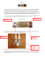
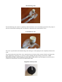
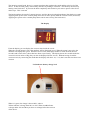
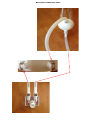
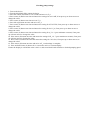
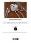
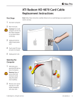
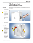
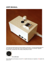
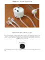
USER MANUAL - ELECTRIC DYNAMIC PUMP
This manual briefly explains the operation of the device.
The points described below are: the on/off button , the current switch, power and charging connectors, water
connectors , final discharge unit, controlled loss valve , regulation intensity knob , display, battery charge
indicator , supplied cylinder and the filling and emptying operation ,the connection tubes , and how best to
use the device and set vacuum values.
The on/off button
The on/off button turn the device on and off. In I position the device is in operation, in O position the device
is off.
The switch
As in the figure above: the switch selects the type of power supply (only for the dual power supplymodel
A/C batteries), with AC batteries or power supply. The switch positioned on the left /black color) uses a
battery supply device. The switch positioned on the right operates the device with AC mains power via a
transformer. To use the battery, keep the selector positioned on the left. To use AC power, keep the switch
positioned to the right. In order to recharge the battery keep the switch positioned to the left. If while using
the battery-powered device the switch is moved to the right, the device will lose power and stop.
The left connector is only used to recharge the battery while the device is not in use. The right connector is
for AC power supply and should only be used to supply the device while it is in use.
RIGHT PUMP
CONNECOTR
Water connectors
LEFT PUMP
CONNECTOR
The pump has two connectors, right and left. The right is the discharge connector and must therefore be
connected to the connector on the left of "Final discharge unit".
DISCHARGE
CONNECTOR
CONNECTED TO
CYLINDER
CONNECTOR 1
LEAK VALVE
CONNECTOR,CO
NNECTED TO
CYLINDER
The left connector of the pump, must be connected to the cylinder connector 1 . CONNECTOR 2
The scheme described above should be followed as pictured. The discharge connector is important , do
not invert it. If it is inverted the pump will not generate any vacuum but there are not obviously dangers or
damage to the device..
Final discharge unit
The final discharge unit must be completely immersed about 6 cm in water during operation of the pump. It
must be connected the discharge tube and the tube connected to the controlled loss valve .
Controlled loss valve
The valve is positioned on the final discharge unit, during use of the pump must be completely immersed in
water.
The white knob on the head of the valve controls the rate of descent of the vacuum. You have to adjust it by
gently tightening or loosening 1 or 2 mm at a time so finding the right setting at your leisure . Valve
adjustments should be made keeping it totally immersed in water If you fully tighten (clockwise) there
would be no leak and the vacuum level would remain stable.
Regulation intensity knob
The intensity control knob, above is a current regulator that regulates the speed and the noise level of the
device. It must be used gently. The intensity increases by turning it clockwise. The intensity decreases by
turning it anti-clockwise. If you turn the knob completely anti-clockwise you remove power to the device
and it stops. This is normal.
The knob regulates the speed of vacuum increase, and also the noise (though moderate) that the device emits.
Applying more power to the vacuum pump draws out air more quickly from the vacuum circuit (clockwise).
Applying less power to the vacuum pump draws out air more slowly (anti-clockwise).
The display
From the display you can display the vacuum value inside the circuit.
When the vacuum pump is active the numbers will be displayed in red. When the pump is not active the
numbers will displayed in green. When the device starts, the display flashes for some seconds (about 2
seconds) and it starts at the values that have been set previously. The display shows the vacuum inside the
vacuum circuit in inches of Hg (they can also be displayed in Bar, Psi etc.) Without having closed the
vacuum circuit, by connecting the small tube the display will show - 0,1/- 0,2, that is normal since there is no
vacuum.
Led indicator battery charge level
When it is green, the charge is about 100%, when is
Yellow indicates a charge from 80% to 30%. When is red indicates
a charge under 30% and then you have to recharge before the next use
of the device.
Description connection tubes
How best to use it
In this section we will explain in a few essential points, and most important how to use the device.
1) Rest the device on a flat surface near the water source, connect final discharge unit to the pump :
the right connector of the pump into the left connector of the final discharge unit , the left connector
of the pump into the cylinder connector 1 , the left connector of final dischage unit into the cylinder
connecot 2 , completely immerse the final discharge unit in water.
2) Wear the cylinder , on the pump and with the knob give maximum power to fill the cylinder , open
completely (unscrew) the leak valve lacaetd on the top of final discharge unit .
3) When the cylinder is almost full of water point it out. As soon it is completely full of water and
without air bubbles inside close (screw) the leak valve and the vacuum reaches the value preset .
The position of the cylinder must be with the tip pointing upwards during filling, as the photo below.
WE STRONGLY RECOMMEND USING WARM WATER IN THIS PUMP. It is generally considered
Warmth assists in achieving the BENEFITS this device is capable of AND PREVENTION of injuries
that can result from excessive pumping (eg red spots).
Setting vacuum values.
The device is equipped with three buttons from which you can regulate the minimum and maximum vacuum
which can be set in two different ways.
Setting minimum vacuum (N_I)
1) To set minimum vacuum turn on the device by turning the power switch on (I position). The display
will show – 0,1/-0,2,
2) now press the central button
3) Press the button on the right
once. You will display the flashing writing N_I present value.
to decrease or press the button on the left
to increase
4) press the central button once more and you have finished setting minimum vacuum.
For example, use the side left and right buttons to set –3,7” Hg. So the value -3.7” Hg that you have just set
means that: when vacuum arrives to -3.7 the device starts and leads the vacuum to the maximum preset value, the
vacuum inside the vacuum circuit will not decrease under -3,7”.
To set the maximum vacuum value vacuum that the device will reach you set a number (H_I). H_I represents the
increase in vacuum from the minimum set vacuum (N_I) (ie Maximum set vacuum = N_I + H_I).
Setting H_I
1. Turn on the device by pressing I, the display will show – 0.1/ -0.2, hold down the central button
for at least 3 seconds, the display will show the writing F 0,
2. press the left button
once, the display will show the writing F 1.
3. Now press the central button four times until the display shows the writing H_I. You increase with
the button on the left and decrease with that on the right.
4. then press again the central button for at least 3 seconds, the display will show the writing – 0,1/-0,2,
and you have now set the maximum value.
Examples
If you want to make:
.
cycles at a minimum vacuum of -4.0 and a maximum vacuum of -9.0: set the minimum value (N_I)
at -4.0 and set H_I value at 5.0.
.
Cycles at a minimum vacuum of -3.3 and maximum vacuum of 10.2: set N_I to – 3.3, set H_I to 6.9.
.
cycles at a minimum vacuum of -4,5, maximum vacuum of - 8,7: set N_I -4,5 and H_I to 4,2.
.
cycles at a minimum vacuum - 5,5 maximum vacuum - 11,0: set N_I to - 5,5 and H_I to 5,5.
Note: If you have -4.0 as minimum value and -8.0 as maximum value, when you modify only the value N_I
that is – 4.0 and you bring it to – 5.0, for example, you will obviously increase the maximum value H_I too,
so it will automatically become - 9.0, so you will have -5.0 as minimum value and -9.0 as maximum value. .
It might seem complicated but once you become familiar with the device it will become quite easy because
if used correctly usually you will only change the maximum value, while you will almost always have the
same minimum value (ie you will normally only modify the H_I value).
You are advised to adjust minimum and maximum values by following this handbook exclusively without
relying on any other menu option, but if you "unconfigure" the menu in error with the buttons under the
display, contact [email protected] , we will help you with reprogramming.
Lithium-ion battery
The dual power supply version of the device includes a lithium-ion battery, a very powerful and safe new
generation battery that can supply the device for some hours, with a range of at least two full hours; the
battery charging must be done exclusively when the device is not in use. The battery must be charged when
necessary, do not charge the battery continually if it is not out of power for about 70/80 % or there will be the
risk of nullifying its duration.
Static pumping
The device has been designed for dynamic pumping. It has a natural slow vacuum leak that is amplified and
regulated by the controlled loss valve. If you wish to use the device for static pumping you have to remember
that is does not maintain a constant vacuum but will always tend to slowly lose vacuum.
Possible causes of malfunctions
The most important thing for a correct operation of the pump is to be sure to have the well sealed vacuum
circuit. If during the session you realize that the vacuum does not reach the predetermined value that the
pump does not suck or not suck enough the thing to do are the following :
1) be sure that the battery is charged, if the LED is red it means that the device must be recharged, with
little power due to low battery, the display may be switched on but does not have enough power to
run the pump so suitable.
2) holding the pump on, disconnect and reconnect all the connectors, push energy and make sure
they are properly engaged, after inserting it to make a half turn to the right and left.
3) verify that the valve knob is screwed loss that is closed, if you get the knob open after filling the
cylinder obviously in the circuit water will circulate freely without reaching any vacuum, if so then
close (screw) the valve knob loss located on the end of the drain.
If the cylinder are continuous and large bubbles of air means that there is a leak in the vacuum
circuit, check that the silicone ring is tightly around the base of the penis, in some cases it may be
necessary to depilation, if not total at least partial ie shorten the pubic hair to prevent it from entering
three ring silicone and the base of the penis by creating mini leaks.
5) If after doing all the above steps the pump does not yet reach the vacuum preset or it hardly reaches,
check all the male and female connectors and make sure there are no hairs stuck inside, even just a
hair happened in the connector can be a cause of loss.
6) Finally, check that there is something blocking the water flow in the circuit, how to do: take the final
unloading, connect a hose to the connector on the right and blow energy on the other end of the pipe,
if it is clogged check that there is something or inside the tube or in the connector of the final
exhaust, if it is free to do exactly the same operation with the connector on the left, and with all three
of the tubes, the tubes and the final unloading must be not obviously clogged.
7) Connect a hose to the connector on the right and one to the left connector of the pump, dip in the
water pipe connected to the left connector of the pump and turn on the device, giving full power. If
the pump runs you will notice that the tube immersed in water vienere sucked water from the hose
and water comes out right, it means that the pump works well.
4)
Water filter .
The device has an internal water filter to prevent debris or hair entering. in the vacuum pump and affecting
its correct operation. I cannot predict when it needs to be cleaned or replaced because it depends on the type
of use and the cleanliness of the water used, but if in case you have a malfunction and you've already made
all the steps described in "Possible causes of malfunctions" and reset the display as described in the last
paragraph of this manual, you can sufficient to clean or replace the filter with the spare you have been
given .
On the underside of the device there is a small opening fixed closed with 2 screws. Unscrew the 2 screws
and the small cover will come off and you will be able to see the filter, which is connected to a tube as in the
following picture
Gently pull the filter out and disconnected by simply pulling tubes but with the other hand holding the hose,
either clean the filter or replace it with this new filter tuck inside as it was before and close by tightening the
2 screws.
To clean the filter just soak it in hot water blow in goth ends to remove any obstructions. When you get good
air flow refit it to the pump.
Checking pump settings
1. Turn on the device.
2. Turn the black knob fully counterclockwise.
3. Press the central (S) button for 3-4 seconds and arrive in F_0.
4. Press center (S) button one time and ensure the settings for uni is inH, if not press up or down arrows to
change the value.
5. Press center (S) button one time arrive at F_0.
6. Press left (up) button one time and arrive at F_1
7. Press center (S) button one time and ensure the setting for oUI is HYS, if not press up or down arrows to
change the value.
8. Press center (S) button one time and ensure the setting for lot is I_n, if not press up or down arrows to
change the value.
9. Press center (S) button one time and ensure the setting for n_I is -3 (your minimum vacuum), if not press
up or down arrows to change the value.
10. Press center (S) button one time and ensure the setting for H_1 is 7 (your maximum vacuum), if not press
up or down arrows to change the value.
11. Press center (S) button one time and ensure the setting for Col is Sor, if not press up or down arrows to
change the value.
12. Press center (S) button one time and arrive at F_1 and settings is complete.
13. Press and hold center (S) button for 3-4 seconds to arrive at vacuum display.
Ensure the display is red and the value is 0.0/0.1, and screw black knob clockwise to desired pumping speed .