1
User manual
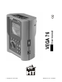
VEGA 76
© Copyright HT ITALIA 2009
Release EN 1.06 - 16/02/2009
VEGA 76
Contents:
1.
PRECAUTIONS AND SAFETY MEASUREMENTS ...................................................3
1.1. General ............................................................................................................................3
1.2. Preliminary instructions ....................................................................................................3
1.3. During use........................................................................................................................4
1.4. After use ...........................................................................................................................4
2.
GENERAL DESCRIPTION .........................................................................................5
2.1. Introduction ......................................................................................................................5
2.2. Features ...........................................................................................................................5
2.3. Initial screen .....................................................................................................................5
3.
PREPARING THE INSTRUMENT ..............................................................................6
3.1. Initial check ......................................................................................................................6
3.2. Instrument power supply ..................................................................................................6
3.3. Calibration ........................................................................................................................6
3.4. Storage.............................................................................................................................6
4.
HOW TO OPERATE ...................................................................................................7
4.1. Instrument description......................................................................................................7
4.2. Keyboard description .......................................................................................................7
4.3. Display description ...........................................................................................................8
4.4. Backlight feature ..............................................................................................................8
5.
MENU GENERAL .......................................................................................................9
5.1. Initial settings ...................................................................................................................9
5.1.1. How to adjust the contrast............................................................................................ 9
5.1.2. How to set date and time ............................................................................................. 9
5.1.3. How to set the language .............................................................................................. 9
5.2. Basic Setting: ANALYZER CONFIG ..............................................................................10
5.2.1. How to set the type of electrical system under test.................................................... 10
5.2.2. How to set the fundamental frequency....................................................................... 10
5.2.3. How to set the current range...................................................................................... 10
5.2.4. How to set the Clamp Type........................................................................................ 11
5.2.5. How to set the value of the transformer voltage ratio (TV RATIO)............................. 11
5.2.6. How to enable/disable the password ......................................................................... 11
5.3. Basic Setting: RECORDER CONFIG ............................................................................12
5.4. ANALYZER MEMORY ...................................................................................................19
5.5. RESET ...........................................................................................................................20
6.
SWITCH FUNCTIONS ..............................................................................................21
6.1. "VOLTAGE" position ......................................................................................................22
6.1.1. Symbols ..................................................................................................................... 22
6.1.2. "METER" mode .......................................................................................................... 23
6.1.3. "HARM" mode ............................................................................................................ 24
6.1.4. "WAVE" mode ............................................................................................................ 25
6.2. "CURRENT" position......................................................................................................26
6.2.1. Symbols ..................................................................................................................... 26
6.2.2. “METER" mode .......................................................................................................... 27
6.2.3. “HARM" mode ............................................................................................................ 28
6.2.4. "WAVE" mode ............................................................................................................ 29
6.3. "POWER" position..........................................................................................................30
6.3.1. Symbols ..................................................................................................................... 30
6.3.2. "METER" mode .......................................................................................................... 31
6.3.2.1. PEAK ENERGY DEMAND .......................................................................32
6.3.3. "WAVE" mode ............................................................................................................ 33
6.4. "ENERGY" position ........................................................................................................34
6.4.1. Symbols ..................................................................................................................... 34
6.4.2. "METER" mode .......................................................................................................... 35
EN - 1
VEGA 76
7.
START A RECORDING ............................................................................................36
8.
DURING A RECORDING..........................................................................................38
9.
STOP A RECORDING OR AN ENERGY MEASUREMENT.....................................39
10. CONNECT THE INSTRUMENT TO A PC.................................................................40
11. MEASURING PROCEDURES ..................................................................................41
11.1.
Using the Instrument in a Single Phase System ....................................................41
11.2.
Using the Instrument in a Three Phase 4 Wire System .........................................42
11.3.
Using the Instrument in a Three Phase 3 Wire System .........................................43
12. MAINTENANCE........................................................................................................44
12.1.
Genaral ...................................................................................................................44
12.2.
Battery replacement ...............................................................................................44
12.3.
Cleaning..................................................................................................................44
12.4.
End of life................................................................................................................44
13. TECHNICAL SPECIFICATIONS...............................................................................45
13.1.
Technical characteristics ........................................................................................45
13.1.1. Compliance ................................................................................................................ 46
13.1.2. Temperature drift........................................................................................................ 46
13.1.3. Safety ......................................................................................................................... 47
13.1.4. General Characteristics.............................................................................................. 47
13.2.
Environment............................................................................................................47
13.2.1. Operating conditions .................................................................................................. 47
13.3.
Accessories ............................................................................................................47
13.3.1. Standard accessories................................................................................................. 47
13.3.2. Optional accessories.................................................................................................. 47
14. APPENDIX 1 – MESSAGES DISPLAYED ...............................................................48
15. APPENDIX 2 – RECORDABLE PARAMETERS: SYMBOLS ..................................49
16. APPENDIX 3 – THEORETICAL OUTLINES.............................................................50
16.1.
Voltage Anomalies (Voltage Sag and Surge).........................................................50
16.2.
Voltage and current Harmonics ..............................................................................50
16.2.1. Theory ........................................................................................................................ 50
16.2.2. Limit values for harmonics ......................................................................................... 51
16.2.3. Presence of harmonics: causes ................................................................................. 52
16.2.4. Presence of harmonics: consequences ..................................................................... 52
16.3.
Power and power factor: definitions .......................................................................53
16.3.1. Conventions on powers and power factors ................................................................ 54
16.3.2. 3 Phase 3 Wire System.............................................................................................. 55
16.4.
Measuring method: outlines ...................................................................................56
16.4.1. Integration periods ..................................................................................................... 56
16.4.2. Power factor calculations ........................................................................................... 56
17. AFTER-SALE SERVICE ...........................................................................................57
17.1.
Warranty .................................................................................................................57
17.2.
Service....................................................................................................................57
EN - 2
VEGA 76
1. PRECAUTIONS AND SAFETY MEASUREMENTS
1.1. GENERAL
This instrument has been designed in compliance with IEC/EN61010-1 directive. For your
own safety and to avoid damaging the instrument we suggest you follow the procedures
hereby prescribed and to read carefully all the notes preceded by the symbol
.
Before and during measurements please be very diligent in following instructions below:
• Do not measure voltage or current in wet or dusty places;
• Do not measure in presence of gas, explosive materials or combustibles;
• Do not touch the circuit under test if no measurement is being taken;
• Do not touch exposed metal parts, unused terminals, circuits and so on;
• Do not use the instrument if it seems to be malfunctioning (i.e. if you notice
deformations, breaks, leakage of substances, absence of messages on the display and
so on);
• Use only cables and accessories approved by HT Italia.
The following symbols are used on meter and in this manual:
Caution: keep to what prescribed by the manual. An incorrect use could damage
the instrument or its components
High voltage: risk of electric shock
Instrument with double insulation
AC voltage and current
1.2. PRELIMINARY INSTRUCTIONS
• This instrument has been designed for use in places with pollution class 2.
• It can be used for voltage and current measurements on installations of excess
voltage category III 600 VAC phase to phase / 300 VAC phase to earth or CATII 350 V
phase to earth up to (and no more than) 2000 meters altitude.
• Please keep to the usual safety standards aimed at:
♦ Protecting against dangerous currents;
♦ Protecting the instrument against incorrect operations.
• Only the accessories supplied with the instrument guarantee compliance with the
safety standards. Accordingly, they must be in good conditions and, if necessary, they
must be replaced with identical models.
• Do not take measurements on circuits exceeding the specified current and voltage
limits.
• Before connecting cables, crocodiles and clamps to the circuit under test, make sure
that the right function has been selected.
EN - 3
VEGA 76
1.3. DURING USE
Please read carefully:
CAUTION
Should you fail to keep to the prescribed instructions you could damage the
instrument and/or its components or endanger your safety.
•
•
•
•
When the instrument is connected to the circuit under test do not touch any unused
terminal.
When measuring current, other currents located near the leads may affect the
measuring accuracy.
When measuring current, always position the wire in the very middle of the jaws in
order to obtain the highest accuracy.
A measured value remains constant if the "HOLD" function is active. Should you notice
that the measured value remains unchanged, disable the “HOLD” function.
1.4. AFTER USE
• After use, turn off the instrument by pressing ON/OFF for a few seconds.
• If you expect not to use the instrument for a long time please keep to the storage
instructions described at paragraph 3.4.
EN - 4
VEGA 76
2. GENERAL DESCRIPTION
2.1. INTRODUCTION
The VEGA76 represent a new approach to the world of electrical measures. Computer
assisted instruments such as this one permit an easy and fast analysis of a huge quantity
of data.
2.2. FEATURES
These instrument are able to:
display in real time the electrical parameters of a single phase and three-phase
systems (with and without neutral wire) and the harmonic analysis of voltages and
currents.
conduct a direct Energy measurement (without memorizing).
memorize (pressing SAVE key) the sampled values of the Parameters present at
instrument input generating a "Smp" record inside instrument memory. It will be
possible to analyze the memorized data ONLY by transferring it to a PC.
record simultaneously (pressing the START key after a proper setting): RMS values
of voltages, currents, corresponding harmonics, active, reactive and apparent powers,
power factors and cosϕ, active, reactive and apparent energies, voltage anomalies
(voltage sag and surge) with 10ms resolution. It will be possible to analyze the
recorded data ONLY by transferring them to a PC.
CAUTION
Please note the difference between memorize and record. These terms
will be used repeatedly in this manual. Please focus on their definitions and
distinctions.
2.3. INITIAL SCREEN
When turning on the instrument by pressing ON/OFF, this screen will appear for a few
seconds:
Vega 76
HT ITALIA
SN: 00000000
VER:x.xx
CALIBRATION DATE
00.00.00
BAUD RATE 57600
Here you can see:
•
•
•
•
serial number of the instrument (SN.:)
firmware software release (VER.:)
calibration date (CALIBRATION:)
transmission speed through serial I/O (Baud Rate)
EN - 5
VEGA 76
3. PREPARING THE INSTRUMENT
3.1. INITIAL CHECK
This instrument has been checked before shipment from an electrical and mechanical
point of view. All possible precautions have been taken in order to deliver it in perfect
condition. Notwithstanding, on receipt of the instrument we suggest that you check it
summarily to make sure that no damage has occurred in transit. Should you find
irregularities please contact the carrier immediately. Furthermore, please make sure that
the parcel contains all the accessories and parts listed at paragraph 13.3. In case of
discrepancies please contact your dealer. Should it be necessary to return the instrument
to the supplier please keep to the instructions given at paragraph 17.
3.2. INSTRUMENT POWER SUPPLY
The instrument can be powered by:
6 batteries 1.5V AA - LR6 series located in the compartment on the back of the
instrument
an external power supply coded A0050 supplied with the instrument.
CAUTION
For recordings use ALWAYS the external power supply (even the
instrument allows the operator to perform a recording using internal
batteries)
The instrument uses sophisticated algorithms to prolong the battery life. Particularly:
The instrument switches OFF the backlight Automatically after 5 seconds.
If the instrument is displaying in real time (and the external power supply is not
connected), after about 5 minutes from the last key pressure or switch rotation the
instrument turns off automatically ("AUTOPOWER OFF" procedure).
If the instrument is recording or is measuring energy (and the external power supply is
not connected), after about 5 minutes from the last key pressure or switch rotation the
instrument starts a special procedure to save the batteries ("ECONOMY MODE"): the
instrument keeps recording but the display is turned off.
3.3. CALIBRATION
The instrument complies with the standards mentioned in this manual. Its performance is
guaranteed for one year from the purchase date.
3.4. STORAGE
To guarantee accurate measurements, after a long storage period in severe environmental
conditions wait until the instrument resumes its normal conditions (see environmental
conditions listed at paragraph 13.2).
EN - 6
VEGA 76
4. HOW TO OPERATE
4.1.
INSTRUMENT DESCRIPTION
LEGEND:
1. Inputs for voltage and currents
2. RS232 serial output
3. Plug for external power supply
4. Display
5. Rotary switch
6. Keyboard
4.2. KEYBOARD DESCRIPTION
The following keys are available.
ON/OFF:
turning on – turning off / Backlight ON (automatic Off after 5 sec.)
F1, F2, F3, F4:
multifunction keys. The various functions are deducible from the
symbols shown on the bottom of the display.
MENU:
ESC:
by pressing MENU it’s possible to check and modify the
recording parameters.
to leave a menu or a sub-menu.
ENTER/HOLD:
double function key:
ENTER: to confirm the settings made
HOLD:
to block the value updating in real time in all the
screens. This function is disabled when recording
or measuring energy. When this function is
enabled it’s not possible to record or take an
energy measurement.
SAVE:
to save in the instrument memory a Record of “Smp” type (see
paragraph 5.4) containing the instantaneous values of voltage
and current present on the instrument inputs. This function is
disabled during a recording.
START/STOP:
to start/stop manually a recording (see chapters 7 and 9).
EN - 7
VEGA 76
4.3.
DISPLAY DESCRIPTION
The display is a graphic module with a resolution of128 x 128 pixels (16384 pixels overall).
Each pixel has a dimension of 0.5mm x 0.5mm, the visible area is a square of 73mm x
73mm.
The first line of the display shows date and time. If not correct, you can set the exact ones
according to the procedure described at paragraph 5.1.2.
On the top right corner of the display you can always see the battery indicator and, if the
external power supply is connected, the corresponding symbol.
27.09.00
17:35:12
27.09.00
VOLTAGE
V1
V2
V3
V12
V23
V31
freq
Phseq
HARM
=
=
=
=
=
=
=
=
17:35:12
VOLTAGE
230.2 V
230.5 V
230.6 V
384.2 V
385.4 V
383.7 V
50.0 Hz
123
V1
V2
V3
V12
V23
V31
freq
Phseq
WAVE
HARM
=
=
=
=
=
=
=
=
230.2 V
230.5 V
230.6 V
384.2 V
385.4 V
383.7 V
50.0 Hz
123
WAVE
These symbols will be omitted in the following illustrations.
4.4. BACKLIGHT FEATURE
When instrument is turned on, pressing briefly the ON button, the backlight will be
enabled. The light will be automatically turned off after 5 seconds.
If the batteries are too low the instrument will disable automatically the backlight function.
Using repeatedly the backlight function, the Battery life will be compromised.
EN - 8
VEGA 76
5. MENU GENERAL
By pressing the MENU key the following screen will be displayed:
MENU GENERAL
ANALYZER MEMORY
RESET
ANALYZER CONFIG
RECORDER CONFIG
CONTRAST
DATE&TIME
LANGUAGE
↓
↑
It’s not possible to enter the MENU during a recording or a Real Time Energy
measurement.
5.1.
INITIAL SETTINGS
5.1.1. How to adjust the contrast
By pressing the keys F1 and F2, position the cursor on the CONTRAST item and confirm it
by pressing the ENTER key.
By pressing the keys F3 and F4, adjust the contrast (higher values correspond to a higher
contrast while lower values correspond to a lower contrast) and press the ENTER key to
SAVE the change or press ESC to quit the modification.
This setting will remain unchanged after turning off the instrument.
5.1.2. How to set date and time
By pressing the keys F1 and F2, position the cursor on the DATE&TIME item and confirm
it by pressing the ENTER key.
By pressing the keys F1 and F2 position the cursor on the Date format (FORMAT) and
pressing the F3 or F4 keys select one of the following Date format:
DD.MM.YY (2 digit for day, 2 digit for Month, 2 digit for Year)
or
MM.DD.YY (2 digit for Month, 2 digit for Day, 2 digit for Year)
Then using F1 and F2 keys position the cursor on the value to be modified and change the
value using F3 and F4 keys.
The time is expressed as hh:mm (2 digit for hours, 2 digit for minutes) military time.
Press the ENTER key to SAVE the change or press ESC to quit the modification.
This setting will remain unchanged also after turning off the instrument.
5.1.3. How to set the language
By pressing the multifunction keys F1 and F2, position the cursor on the LANGUAGE (EN)
or LINGUA (IT) item and confirm it by pressing the ENTER key.
By pressing the multifunction keys F1 and F2, position the cursor on the desired language
and press the ENTER key to SAVE the change or press ESC to quit the modification.
This setting will remain unchanged after turning off the instrument.
EN - 9
VEGA 76
5.2. BASIC SETTING: ANALYZER CONFIG
Selecting the ANALYZER CONFIG item and pressing the ENTER Key, the following page
will be displayed:
ANALYZER CONFIG
SYSTEM
:3PH4W
FREQUENCY:50HZ
CURRENT RANGE:1000A
CLAMP TYPE: STD
TV RATIO:0001
PASSWORD:ON
↓
↑
+
-
This page of setting can be confirmed by pressing the ENTER key or cancelled by
pressing the ESC key.
5.2.1. How to set the type of electrical system under test
This parameter permits you to select the type of electrical system under test among the
following configurations:
SINGLE: single phase system
3PH3W: 3 wires system (three-phase system without neutral) (see
paragraph 16.3.2)
3PH4W: 4 wires system (three-phase system with neutral)
The connections to the instrument inputs will have to be in keeping with the type of system
selected.
Position the cursor on the corresponding word by pressing the keys F1 and F2 and set the
desired value by pressing the keys F3 and F4.
5.2.2. How to set the fundamental frequency
Position the cursor on the corresponding word by pressing the keys F1 and F2 and select
the network frequency between the possible values 50Hz and 60Hz by pressing the keys
F3 and F4. This parameter is important ONLY if the input voltage is not sufficient to
recognize the value of the frequency (for example, only the clamps for the current
measurement are connected). In this case the instrument generates an internal
synchronism equal to the value of the set frequency.
5.2.3. How to set the current range
The value of this parameter must be always equal to the full scale of the current
clamps used to take the measurement. In case multi-scale clamps are used, the value of
this parameter must be equal to the scale selected on the clamps.
Set the desired value by pressing the keys F3 and F4.
EN - 10
VEGA 76
5.2.4. How to set the Clamp Type
The value of this parameter must be always equal to the clamp type you are using.
Two types of clamps are available:
STD:
for Standard clamps or Current Transformer
FlexINT: for Flexible clamps without any electronic control box
FlexEXT: for Flexible clamps with their own electronic control box
Flex33d: for Flexible clamps without any electronic control box marked with
“HTFLEX33d” code (see herewith picture)
Set the desired value by pressing the keys F3 and F4.
CAUTION
If FlexINT or Flex33d is selected, the current range could be set only to
1000A or 3000A
5.2.5. How to set the value of the transformer voltage ratio (TV RATIO)
The instrument can also be interfaced with step-down transformers in the equipment under
test: it can display the value of he voltages present on the primary winding of these
transformers. To do this it will be necessary to set the value of the transformers’ windings
ratio from 2:1 to 3000:1. The default is set at 1:1 for measurements of none transformer
systems.
Select “TV RATIO” in the ANALYZER CONFIG menu. Set the desired value by pressing
the keys F3 and F4.
5.2.6. How to enable/disable the password
The instrument is provided with a protective routine to avoid the risk of being disturbed or
interrupted during a recording or an energy measurement. Once a recording or a direct
energy measurement has been started (with the option “PASSWORD” enabled), after
about 3 minutes from the last key pressure or switch rotation it won’t be possible to press
START/STOP to stop the recording, “PASSWORD” will be displayed and it will be
necessary to insert the password.
In order to insert the password (which is not changeable), press the multifunction keys in
the following sequence (within 10 seconds):
F1, F4, F3, F2
If you wait more than about 10 seconds the display will return to the meter mode and the
instrument will continue recording. If you insert a wrong password the message “Password
error” will be displayed under “PASSWORD”. After a few seconds the display will return to
meter mode and the instrument will continue recording. In order to enable/disable this
option the correct password will have to be entered. The display will return to meter mode
and START/STOP will have to be pressed again to stop the recording. You will then need
to re-enter the “ANALYZER CONFIG” menu and scroll up or down to the item
“PASSWORD: ON” using the keys F1 and F2. Then turn the password off by pressing the
keys F3 and F4.
EN - 11
VEGA 76
5.3.
BASIC SETTING: RECORDER CONFIG
This option allows you to check and eventually modify the recording parameters and the
selected parameters (up to a maximum of 64). The calculation of the selected values is not
affected by the rotary switch position. If the number of selected values exceeds 64 the
message "too many param" will be displayed. The MENU mode is divided into 4 separate
sub-pages:
1st page:
This page allows you to set the START/ STOP mode (AUTO or
MANUAL), the START and STOP time if AUTO mode is selected, the
Integration Period value, the Enabling/Disabling of Voltage Anomalies
detection, the Enabling/Disabling of Harmonics detection. Press ENTER
to confirm the settings and pass to the following page.
Press ESC to leave the Menu without modifying the existing parameters.
2nd page:
This page is devoted to the settings relevant to the VOLTAGE recording.
Press ENTER to confirm the settings and pass to the following page.
Press ESC to leave this page without modifying the existing parameters.
From this page you can enter the sub-page “Harmonics” which permits to
select the voltage harmonics to be recorded.
Press ENTER to confirm the settings and leave the “Menu Harmonics".
Press ESC to leave the "Menu Harmonics" without modifying the existing
parameters.
3rd page:
This page is devoted to the settings relevant to the CURRENT recording.
Press ENTER to confirm the settings and pass to the following page.
Press ESC to leave this page without modifying the existing parameters.
From this page you can enter the sub-page “Harmonics” which permits to
select the current harmonics to be recorded.
Press ENTER to confirm the settings and leave the “Menu Harmonics".
Press ESC to leave the "Menu Harmonics" without modifying the existing
parameters.
4th page:
Menu composed of two sub-pages devoted to the selection of the
POWERS and ENERGIES to be recorded. From this page you can enter
the sub-page “POWER” and “ENERGY” which permits to select the
parameters to be recorded.
Selecting the active powers for the recording, the corresponding active
energies will be automatically selected.
Selecting the reactive powers for the recording, the corresponding reactive
energies will be selected.
Press ENTER to leave this page confirming the modifications made.
Press ESC to leave the "Menu" without modifying the existing parameters.
The various pages of the "RECORDER CONFIG" can be schematics as follows:
EN - 12
VEGA 76
MENU
To Select MANUAL or AUTOMATIC
start/stop mode, place the cursor on
MANU or AUTO using the key F1 or
F2 and select the desired mode using
F3 or F4.
RECORDER CONFIG
START
MANU
Use the keys F1, F2 to position the
cursor on the desired word and use
the keys F3 / F4 to select / deselect
the desired parameter (it’s selected
if marked in black).
Press ENTER to confirm and leave
the Menu keeping the settings
made.
Press ESC to leave the Menu
without modifying the existing
parameters.
STOP
MANU
INT. PERIOD: 15min
HARM REC: ON
ANOM REC: ON
↓
↑
+
-
st
1 Page of the RECORDER
CONFIG MENU
Use the keys F1, F2 to position the
cursor on the desired word and use
the keys F3 / F4 to modify the
value.
Press ENTER to confirm and
proceed inside the Menu the Menu
keeping the settings made.
Press ESC to leave the Menu
without modifying the existing
parameters.
ENTER
RECORDER CONFIG
RECORDER CONFIG
RECORDER CONFIG
VOLTAGE:
V1
VOLTAGE REC:
V12 V32 V31
VOLTAGE REC:
V1 V2 V3
V12 V32 V31
HARM. REC:Pg (ON)
HARM. REC:Pg (ON)
HARM. REC:Pg (ON)
Vref P-N: 230V
LIM+: 06% (243.8V)
LIM-: 10% (207.0V)
Vref P-P: 400V
LIM+: 06% (424.0V)
LIM-: 10% (360.0V)
Vref P-N: 230V
LIM+: 06% (243.8V)
LIM-: 10% (207.0V)
↓
↑
+
↓
-
Example of 2nd page in singlephase mode with ANOM flag
enabled
↑
+
-
Example of 2nd page in “3
wires” three-phase mode with
ANOM flag enabled
If you want to change Voltage Harm. Selection place the
cursor on the corresponding “Pg” symbol then Press F3
RECORDER CONFIG
VOLTAGE HARMONICS
ENTER
05
12
19
26
33
40
47
Thd
06
13
20
27
34
41
48
↓
DC
07
14
21
28
35
42
49
01
08
15
22
29
36
43
↑
02
09
16
23
30
37
44
+
03
10
17
24
31
38
45
04
11
18
25
32
39
46
-
Example of sub-page
"VOLTAGE HARMONICS"
EN - 13
↓
↑
+
-
Example of 2nd page in “4 wires”
three-phase mode with ANOM
flag enabled
Use the keys F1, F2 to position
the cursor on the desired
voltage harmonic and use the
keys F3 / F4 to select /
deselect (it’s selected if
highlighted in black).
Press ENTER to confirm.
Press ESC to leave the Menu
without modifying the existing
settings.
The instrument will record the
values of the selected
harmonics corresponding to
the voltages selected in one of
the two pages of the Menu
previously illustrated.
VEGA 76
Use the keys F1, F2 to position
the cursor on the desired word
and use the keys F3 / F4 to
modify the value or select /
deselect the desired parameter
(it’s selected if marked in black).
Press ENTER to confirm.
Press ESC to leave the Menu
without modifying the existing
settings.
From 2nd page
of RECORDER CONFIG MENU
ENTER
RECORDER CONFIG
RECORDER CONFIG
RECORDER CONFIG
CURRENT REC:
I1
CURRENT REC:
I1 I2 I3
CURRENT REC:
I1 I2 I3 IN
HARM. REC:Pg (ON)
HARM. REC: Pg (ON)
HARM. REC:Pg (ON)
↓
↑
+
↓
-
Example of 3rd page in singlephase mode
↑
+
-
Example of 3rd page in “3
wires” three-phase mode
If you want to change Current Harm. Selection place
Cursor on the corresponding “Pg” symbol then Press F3
RECORDER CONFIG
CURRENT HARMONICS
ENTER
05
12
19
26
33
40
47
Thd
06
13
20
27
34
41
48
↓
DC
07
14
21
28
35
42
49
01
08
15
22
29
36
43
↑
02
09
16
23
30
37
44
+
03
10
17
24
31
38
45
04
11
18
25
32
39
46
-
Example of sub-page
"CURRENT HARMONICS"
EN - 14
↓
↑
+
-
Example of 3rd page in “4 wires”
three-phase mode
Use the keys F1, F2 to position
the cursor on the desired current
harmonic and use the keys F3 /
F4 to select / deselect (it’s
selected if marked in black).
Press ENTER to confirm.
Press ESC to leave the Menu
without modifying the existing
settings.
The instrument will record the
values of the selected harmonics
corresponding to the currents
selected in one of the two pages
of the Menu previously
illustrated.
VEGA 76
From 3rd page
of RECORDER CONFIG MENU
ENTER
RECORDER CONFIG
CO-GENERATION:ON
POWER:Pg
ENERGY:Pg
↓
↑
+
-
Example of 4th page
In order to select the POWER to be recorded use the keys
F1, F2 to position the cursor on the corresponding “Pg”
Symbol and then press F3
ENTER
RECORDER CONFIG
RECORDER CONFIG
P1
Pf1
Q1i
dPf1
Q1c
S1
Pt
Qti
Qtc
St
Pft
P12
Q12i
Q12c
S12
dPft
↓
↑
+
-
↓
↑
Example of POWER sub-page in
single-phase mode
RECORDER CONFIG
P32
Q32i
Q32c
S32
+
Pt
Qti
Qtc
St
Pfi
dPfi
-
Example of POWER sub-page
in “3 wires” three-phase mode
↓
P1
Q1i
Q1c
S1
Pf1
dPf1
P2
Q2i
Q2c
S2
Pf2
dPf2
↑
+
P3
Q3i
Q3c
S3
Pf3
dPf3
-
Example of POWER sub-page in
“4 wires” three-phase mode
CAUTION
Selecting the active powers for the recording, the corresponding active energies will
be automatically selected.
Selecting the reactive powers for the recording, the corresponding reactive energies
will be selected.
EN - 15
VEGA 76
From 3rd page
of RECORDER CONFIG MENU
ENTER
RECORDER CONFIG
CO-GENERATION:ON
POWER:Pg
ENERGY:Pg
↓
↑
+
-
Example of 4th page
In order to select the ENERGIES to be recorded use the
multifunction keys F1, F2 to position the cursor on the
corresponding “Pg” Symbol and then press F3
ENTER
RECORDER CONFIG
Ea1
↓
RECORDER CONFIG
Eri1 Erc1 Es1
↑
+
-
Example of ENERGY sub-page
in single-phase mode
Eat
↓
RECORDER CONFIG
Erit Erct Est
↑
+
-
Example of ENERGY sub-page
in “3 wires” three-phase mode
Eat
Erit
Erct
Est
↓
Ea1
Eri1
Erc1
Es1
Ea2
Eri2
Erc2
Es2
Ea3
Eri3
Earc3
Es3
↑
+
-
Example of ENERGY sub-page
in “4 wires” three-phase mode
CAUTION
Selecting/deselecting the active energies for the recording, the corresponding active
powers will be automatically selected/deselected.
Selecting/deselecting the reactive energies for the recording, the corresponding
reactive powers will be selected/deselected
Selecting/deselecting the reactive energies for the recording, the corresponding
reactive powers will be selected/deselected.
EN - 16
VEGA 76
Symbols
START:MAN
STOP:MAN
START:AUTO
STOP:AUTO
INT. PERIOD
HARM REC.
ANOM REC.
Description
Advised settings
The recording of all the selected parameters will start at 00
seconds after pressing START/STOP (see chapter 7).
The recording of all the selected parameters will be interrupted
manually by pressing START/STOP (see chapter 9).
The recording of all the selected values will be started / interrupted
at the set dates and times. In order to start the recording the user
will have to press START/STOP to set the instrument in Stand-by
mode until the start date and time previously set (see chapter 7)).
The value of this parameter determines every how many seconds
15min
the values of all the selected parameters will be memorized
(see chapter 16.4.1). Available choices:
5sec,10sec,30sec,1min,2min 5min,10min, 5min, 30min, 60min.
ON = the instrument will record the values of the selected
voltage and current harmonics corresponding to the
voltages and currents selected in the corresponding
pages “Voltage” and “Current”.
Example: If the following Parameters are selected:
a) Phase Voltage 1 and 2, THd, Harmonics 1,3,5.
b) Phase Current 2 and 3, THd, Harmonics 3,5,7.
The instrument will record:
a) The Phase Voltage 1 and 2, THD and Harmonics 1,3,5 of
the Phase Voltage 1 and 2 while it will not record
anything about Phase Voltage 3
b) The Phase Current 2 and 3, THD and Harmonics 3,5,7 of
the Phase Current 2 and 3 while it will not record nothing
about Phase Current 1
OFF = the instrument will not record any voltage or current
harmonic selected
ON = the Instrument will record Voltage Anomalies (voltage Sag
and Surge) (see paragraph 16.1)
OFF = the instrument will not record any voltage Sag and Surge
☺
☺
☺
☺
☺
☺
V1, V2, V3
V12, V23 or V32,
V31
RMS value of the voltage of phase 1, phase 2, phase 3
respectively, values of the phase-to-phase voltages 1-2, 2-3 or 3- Single phase: V1
3 wires V12 V32 V31
2 and 3-1.
4 wires V1, V2, V3
THD, DC, 01...49
Voltage Total Harmonic Distortion, DC Component, 01..49
Harmonics respectively
☺
THD,01,03,05,07
RMS reference value for Voltage used in Voltage Anomalies
Vref
detection (Voltage Sag and Surge). The Reference is:
(only if ANOM. REC flag a) Voltage Phase to Neutral for Single Phase and 4 wires three Single phase: 230V
3 wires: 400V
phase system
has been set ON)
4 wires 230V
b) Voltage Phase to Phase for 3 wires three phase system
High and Low Voltage Percent threshold used in Voltage
Anomalies detection (Voltage Sag and Surge).
Example: Three Phase System 4 wires.
LIM+, LIMVref = 120, LIM+= 6%, LIM-=10% =>
Single phase: 120V
(only if ANOM. REC flag
High Lim = 127.2V, Low Lim = 108.0V
3 wires: 480V
has been set ON)
The Instrument will detect a voltage Anomalies if the RMS
4 wires 277V
Voltage Values (calculated every 10ms) beyond the above
calculated thresholds (see paragraph 16.1).
☺
☺
☺
I1, I2, I3, IN
THD, DC, 01..49
RMS value of the current of phase 1, phase 2, phase 3 and of the
Single phase: I1
neutral respectively.
3 wires: I1, I2, I3
4 wires I1, I2, I3, IN
Current Total Harmonic Distortion, DC Component, 01..49
Harmonics respectively
EN - 17
☺
THD,01,03,05,07
VEGA 76
CO-GENERATION
Pt, P1, P2, P3,
P12, P32
ON = the instrument is able to face situations of CO-GENERATION
of electrical equipment (that is, the equipment under test is
able to generate energy besides absorbing it). Accordingly, the
instrument will record the powers and energies both absorbed
and generated (see paragraph 16.3.1). If this flag is enabled
the maximum number of parameters which can be
selected decrease to 38.
OFF = the instrument will record ONLY the powers and energies
absorbed.
Values of the active power (total, of phase 1, phase 2 and phase 3)
(only for 3 wires measurement) value of the power measured by
the Wattmeter 1-2 and 3-2 respectively
☺
☺
Single phase: P1
3 wires: Pt
4 wires Pt, P1, P2, P3
Values of the inductive reactive power (total, of phase 1, phase 2,
Qti, Q1i, Q2i, Q3i, phase 3)
(only for 3 wires measurement) value of the reactive inductive
Q12i, Q32i
Single phase: Q1i Q1c
power measured by the VAR meters 1-2 and 3-2 respectively
3 wires: Qti Qtc
Values of the capacitive reactive power (total, of phase 1, phase 4 wires Qti Q1i Q2i, Q3i
Qtc, Q1c, Q2c, Q3c, 2, phase 3)
Qtc Q1c Q2c, Q3c
Q12c, Q32c
(only for 3 wires measurement) value of the reactive capacitive
power measured by the VA meters 1-2 and 3-2 respectively
☺
Values of the apparent power (total, of phase 1, phase 2, phase
St, S1, S2, S3, S12, 3)
S32
(only for 3 wires measurement) value of the power measured by
the VA meters 1-2 and 3-2 respectively
Pft, Pf1, Pf2, Pf3
dpft, dpf1, dpf2, dpf3
Values of the power factors (total, of phase 1, phase 2 and phase
3 respectively)
☺
Single phase: S1
3 wires: St
4 wires St, S1, S2, S3
☺
Single phase: Pf1 dPf1
3 wires: Pft dPft
Values of the cosϕ (total, of phase 1, phase 2 and phase 3
4 wires Pft Pf1 Pf2 Pf3
respectively)
dPft dPf1 dPf2 dPf3
☺
Eat, Ea1, Ea2, Ea3
Values of the active energy (total, of phase 1, phase 2, phase 3)
Erit, Eri1, Eri2, Eri3
Values of the inductive reactive energy (total, of phase 1, phase 2
and phase 3)
Single phase: Ea1
3 wires: Eat
4 wires Eat Ea1 Ea2 Ea3
☺
Single phase: Eri1 Erc1
3 wires: Erit Erct
Values of the capacitive reactive energy (total, of phase 1, phase 4 wires Erit Eri1 Eri2
Erct, Erc1, Erc2, Erc3
Eri3
2, phase 3)
Erct Erc1 Erc2 Erc3
☺
Est, Es1, Es2, Es3
Values of the Apparent Energy (total, of phase 1, phase 2, phase 3)
Single phase: Es1
3 wires: Est
4 wires Est Es1 Es2 Es3
The value of the network frequency is automatically selected if at least one phase voltage (for the single-phase mode or the
4 wires three phase mode) or at least one phase-to-phase voltage (for the 3 wires three phase mode) is selected.
The symbols "i" and "c" stand for reactive powers (Q), power factors (Pf) and cosϕ (dpf) inductive and capacitive respectively.
Selecting a power factor (Pf) or a cosϕ (dPf) for the recording automatically their inductive value and their capacitive value will be
recorded separately.
For eventual messages displayed see appendix 1 – MESSAGES DISPLAYED.
EN - 18
VEGA 76
5.4. ANALYZER MEMORY
This option permits you to display:
The present content of the instrument memory
The size of the memorized data
The residual space available for future recordings (expressed in days and hours)
All the stored data can be displayed only if downloaded to a PC with the operating
software.
After selecting “ANALYZER MEMORY” from the Main Menu the screen below will be
displayed
ANALYZER MEMORY
01
02
03
04
05
06
Smp
Rec
R&a
Rec
R&a
Rec
02.01 01:23
02.01-02.01
02.01-02.01
02.01-02.01
02.01-02.01
04.01-05.01
DATA SIZE:0.11Mb
REC TIME: 0d.06h
LAST
ALL
↑
↓
Example of ANALYZER
MEMORY screen
Rec:
R&a:
Smp:
DATA SIZE:
REC TIME:
recordings effected with respective Start and Stop dates expressed in
the format “day.month” (start) – “day.month” (stop) without Voltage Sag
and Surge detection.
recordings effected with respective Start and Stop dates expressed in
the format “day.month” (start) – “day.month” (stop) with Voltage
Anomalies (Sag and Surge) detection (only for Skylab).
values of the samples of voltage and current stored by pressing SAVE.
dimensions of the data saved in the instrument memory.
amount of memory available, calculated on the basis of the parameters
selected for recording, therefore the most complete one (expressed in the
format “days.hours”) to make recordings.
The maximum quantity of Rec + R&a + Smp which can be contained by the instrument is 35.
Following keys are enabled:
F1, F2:
F3:
F4:
(only if the quantity of Rec+R&a+Smp is higher than 7) to run over all
the recordings stored in the instrument memory.
to cancel the last recording effected.
to cancel all the recordings effected.
EN - 19
VEGA 76
5.5. RESET
This option re-establishes the default settings of the instrument.
The default settings of the instrument consist of:
The “not modified” items are not interested by RESET command
ANALYZER CONFIG:
Frequency:
Full scale of the clamps:
Transforming ratio of voltmetric transformers:
Clamp Type:
Type of electrical equipment:
Password:
50Hz
1000A
1
Flex33d
4 wires
enabled
RECORDER CONFIG:
Start:
Manual (the recording is started
at 00 sec mark on clock after pressing
the START/STOP key)
Stop:
Manual
Integration period:
15min
Recording of harmonics:
ON
Recording of Voltage anomalies (Sag and Surge):
ON
Voltage Reference for Sag and Surge detection:
230V
Upper Limit for Sag and Surge detection:
6%
Lower Limit for Sag and Surge detection:
10%
Selected voltages:
V1, V2, V3
Selected voltage harmonics:
THD, 01, 03, 05, 07
Selected currents:
I1, I2, I3, IN
Selected current harmonics:
THD, 01, 03, 05, 07
CO-GENERATION:
OFF
Powers, Pf and cosϕ selected:
Pt, P1, P2, P3
Qti, Q1i, Q2i, Q3i
Qtc, Q1c, Q2c, Q3c
St, S1, S2, S3
Pft, Pf1, Pf2, Pf3
dpft, dpf1, dpf2, dpf3
Energies:
Eat, Ea1, Ea2, Ea3
Erit, Eri1, Eri2, Eri3
Erct, Erc1, Erc2, Erc3
Est, Es1, Es2, Es3
The RESET command will not erase the instrument’s memory.
EN - 20
VEGA 76
6. SWITCH FUNCTIONS
For a simple usage, the main functions of the instrument can be selected by rotating the
switch:
Position "VOLTAGE": to be used to display voltage and corresponding harmonics
(see paragraph 6.1)
Position "CURRENT": to be used to display current and corresponding harmonics
(see paragraph 6.2)
Position "POWER":
it permits to display all the parameters measurable by the
instrument: voltage, current, active, reactive and apparent
power, power factor, cosϕ and energy (see paragraph 6.3)
Position "ENERGY":
to be used to display active, reactive and apparent power,
power factor, cosϕ and energy (see paragraph 6.4)
More practically, we may schematize the right procedure of use as follows:
1. Check and eventually modify the basic settings of the instrument
2. By rotating the switch, select the type of measurement to be taken
3. Connect the instrument to the electrical system to be tested
4. Evaluate the values of the parameters under test
5. If you want to record:
a) Decide what to record
b) Press MENU and check if the existing parameters meet your requirements
6. Connect the External Power Supply
7. Start the recording by pressing START/STOP.
EN - 21
VEGA 76
6.1. "VOLTAGE" POSITION
This function permits you to display in real time the RMS value of AC/DC voltage, the peak
and Thd value of the 3 phase voltages (see paragraph 16.2), the waveform and the
harmonic spectrum of the 3 phase voltages.
6.1.1. Symbols
The VOLTAGE position has three working modes:
METER
WAVE
HARM
These modes will be described in detail in the next paragraphs. The used symbols are
described below:
Symbol
V1, V2, V3
V12, V23 or V32, V31
Vpk1, Vpk2, Vpk3,
Vpk12, Vpk32
h01 ÷ h49
ThdV
freq
Phseq
Description
RMS value of the voltage of phase 1, phase 2, phase 3 respectively
RMS Value of the phase to phase voltages
Peak value of the voltage of phase 1, phase 2, phase 3 and of the phase to phase
voltage 12 and 32 respectively
Harmonic 01 ÷ Harmonic 49.
Factor of total harmonic distortion of the voltage (see paragraph 16.2).
Network frequency
Phase sequence indicator
"123"→ correct
"132"→ inverted
"023"→ null voltage on the black wire
"103"→ null voltage on the red wire
"120"→ null voltage on the blue wire
"100"→ null voltages on the red and blue wires
"020"→ null voltages on the black and blue wires
"003"→ null voltages on the black and red wires
Tab. 1: Symbols used in the position VOLTAGE
EN - 22
VEGA 76
6.1.2. "METER" mode
On rotating the switch to this position the instrument selects automatically the METER
mode corresponding to one of the below screens according to the settings made as per
paragraph 5.2.
27.09.00
17:35:12
27.09.00
SINGLE PHASE
VOLTAGE
V1
Vpk1
ThdV
freq
HARM.
=
=
=
=
230.2 V
325.5 V
0.0
%
50.0 Hz
WAVE
27.09.00
VOLTAGE
V12
V32
V31
freq
HARM.
Example of screen in singlephase mode
17:35:12
=
=
=
=
384.2 V
385.4 V
383.7 V
50.0 Hz
WAVE
Example of screen in “3 wires”
three-phase mode
17:35:12
VOLTAGE
V1
V2
V3
V12
V23
V31
freq
Phseq
HARM.
=
=
=
=
=
=
=
=
230.2 V
230.5 V
230.6 V
384.2 V
385.4 V
383.7 V
50.0 Hz
123
WAVE
Example of screen in “4 wires”
three-phase mode
The symbols used are described in Tab. 1.
For eventual messages displayed see appendix 1 – MESSAGES DISPLAYED.
Following keys are enabled:
F1:
to pass to "HARMONIC" mode (see paragraph 6.1.3).
F2:
to pass to "WAVE" mode (see paragraph 6.1.4).
SAVE:
to save in the instrument memory a record of “Smp” type (see
paragraph 5.4) containing the instantaneous values of voltage and
current present on the instrument inputs. This function is disabled
during a recording.
ENTER/HOLD: to enable/disable the HOLD function (updating interruption) of the
displayed data. All the previous functions remain however available.
When the HOLD function is enabled, the word HOLD is displayed.
When this function is enabled it’s not possible to record or take an
energy measurement. This function is disabled during a recording or
an energy measurement.
MENU:
to enter in the MENU mode and change the instrument settings (see
paragraph 5.2 and 5.3). It’s not possible to enter the configuration
MENU during a recording or an energy measurement.
START/STOP: to record selected parameters according to the instrument’s settings
(see chapter 7).
EN - 23
VEGA 76
6.1.3. "HARM" mode
Selecting the HARM mode one of the below screens will be displayed according to the
settings made as per paragraph 5.22. The screens show the harmonics (see paragraph
16.2) of the phase or phase-to-phase voltage.
27.09.00
V1
h03
h03
ThdV
17:35:12
= 230.2
= 10.2
=
4.3
= 11.0
h49
←
V
V
%
%
27.09.00
V12
h03
h03
ThdV
→
Example of screen in singlephase system
ChgP
17:35:12
= 400.2
= 14.2
=
3.5
= 11.0
h49
←
V
V
%
%
27.09.00
V1 =
h03
h03
ThdV
→
Example of screen in “3 wires”
three-phase system
ChgP
17:35:12
230.2
V
= 10.2
V
=
4.3
%
= 11.0
%
h49
←
→
Example of screen in “4 wires”
three-phase system
The symbols used are described in Tab. 1. For eventual messages displayed see
appendix 1 – MESSAGES DISPLAYED. The displayed histograms represent the harmonic
content of the voltage under test. The value of the first harmonic h01 (fundamental at
50Hz) is not represented in scale along with the other harmonics in order to maximize the
display of the latter. In case both voltage and current are connected to the instrument
inputs, eventual negative values of the harmonics (therefore represented under the
horizontal axis), indicate that such voltage harmonics are “generated” by the load.
Following keys are enabled:
F3, F4:
to move the cursor of the selected harmonic leftwards and rightwards
respectively. At the same time the values relevant to the order no. of
the selected harmonic and to the corresponding absolute and relative
values (calculated on the basis of the fundamental) are updated.
F1
(only for three-phase mode): to display the values of the harmonics of
the other voltages available. The voltage displayed is indicated above
the F3 key.
F2:
to display the page of the harmonics h01 ÷ h24 (symbol h24) or that of
the harmonics h25 ÷ h49 (symbol h49).
ESC:
to return back to METER mode (see paragraph 6.1.2).
SAVE:
to save in the instrument memory a record of “Smp” type (see
paragraph 5.4) and the instantaneous values of voltage and current
present on the instrument inputs. This function is disabled during a
recording.
ENTER/HOLD: to enable/disable the HOLD function (updating interruption) of the
displayed data. All the previous functions remain however available.
When the HOLD function is enabled, the word HOLD is displayed.
When this function is enabled it’s not possible to record or take an
energy measurement. This function is disabled during a recording or
an energy measurement.
MENU:
to enter in the MENU mode and change the instrument settings (see
paragraph 5.2 and 5.3). It’s not possible to enter the configuration
MENU during a recording or an energy measurement.
START/STOP: to record selected parameters according to the instrument’s settings
(see chapter 7).
EN - 24
VEGA 76
6.1.4. "WAVE" mode
Selecting the WAVE mode one of the below screens will be displayed according to the
settings made as per paragraph 5.2. The screens show the waveform of the phase or
phase-to-phase voltage.
27.09.00
17:35:12
27.09.00
17:35:12
27.09.00
17:35:12
5:12
V1
= 230.2
Vpk1 = 325.5
freq = 50.0
V
V
Hz
V12 = 400.2
Vpk12= 565.5
freq = 50.0
V
V
Hz
ChgP
Example of screen in singlephase system
V1
= 230.2
Vpk1 = 325.5
freq = 50.0
V
V
Hz
ChgP
Example of screen in “3 wires”
three-phase system
Example of screen in “4 wires”
three-phase system
The symbols used are described in Tab. 1.
For eventual messages displayed see appendix 1 – MESSAGES DISPLAYED.
Following keys are enabled:
F1:
(only for three-phase mode): to display the values corresponding to
the following phase.
ESC:
to return back to METER mode (see paragraph 6.1.2).
SAVE:
to save in the instrument memory a record of “Smp” type (see
paragraph 5.4) containing the instantaneous values of voltage and
current present on the instrument inputs. This function is disabled
during a recording.
ENTER/HOLD: to enable/disable the HOLD function (updating interruption) of the
displayed data. All the previous functions remain however available.
When the HOLD function is enabled, the word HOLD is displayed.
When this function is enabled it’s not possible to record or take an
energy measurement. This function is disabled during a recording or
an energy measurement.
MENU:
to enter in the MENU mode and change the instrument settings (see
paragraph 5.2 and 5.3). It’s not possible to enter the configuration
MENU during a recording or an energy measurement.
START/STOP: to record selected parameters according to the instrument’s settings
(see chapter 7).
EN - 25
VEGA 76
6.2. "CURRENT" POSITION
This function permits to display in real time the RMS value of AC/DC currents, the peak
and Thdl value (see paragraph 16.2) of the 3 phase currents, the waveform and the
harmonic spectrum of the 3 phase currents.
6.2.1. Symbols
The CURRENT position has three working modes:
METER
WAVE
HARM
These modes will be described in detail in the next paragraphs.
The symbols used are described below:
Symbol
I1, I2, I3
IN
Ipk1, Ipk2, Ipk3
h01 ÷ h49
ThdI
freq
Description
RMS value of the current of phase 1, phase 2, phase 3 respectively
RMS value of the current on the neutral
Peak value of the current of phase 1, phase 2, phase 3 respectively
Harmonic 01 ÷ harmonic 49.
Total harmonic distortion factor of the current (see paragraph 16.2).
Network frequency
Tab. 2: Symbols used in the position CURRENT
EN - 26
VEGA 76
6.2.2. “METER" mode
On rotating the switch to this position the instrument selects automatically the METER
mode corresponding to one of the screens below according to the settings made as per
paragraph 5.2.
27.09.00
17:35:12
27.09.00
SINGLE PHASE
CURRENT
I1
Ipk1
ThdI
freq
HARM.
=
=
=
=
30.21 A
49.53 A
23.06 %
50.0 Hz
WAVE
27.09.00
CURRENT
I1
I2
I3
freq
HARM.
Example of screen in singlephase mode
17:35:12
=
=
=
=
30.21 A
23.53 A
23.06 A
50.0 Hz
WAVE
Example of screen in “3 wires”
three-phase mode
17:35:12
CURRENT
I1
I2
I3
IN
freq
HARM.
=
=
=
=
=
30.21 A
23.53 A
23.06 A
8.4 A
50.0 Hz
WAVE
Example of screen in “4 wires”
three-phase mode
The symbols used are described in Tab. 2.
For eventual messages displayed see appendix 1 – MESSAGES DISPLAYED.
Following keys are enabled:
F1:
to pass to "HARMONIC" mode (see paragraph 6.2.3).
F2:
to pass to "WAVE" mode (see paragraph 6.2.4).
SAVE:
to save in the instrument memory a record of “Smp” type (see
paragraph 5.4) containing the instantaneous values of voltage and
current present on the instrument inputs. This function is disabled
during a recording.
ENTER/HOLD: to enable/disable the HOLD function (updating interruption) of the
displayed data. All the previous functions remain however available.
When the HOLD function is enabled, the word HOLD is displayed.
When this function is enabled it’s not possible to record or take an
energy measurement. This function is disabled during a recording or
an energy measurement.
MENU:
to enter in the MENU mode and change the instrument settings (see
paragraph 5.2 and 5.3). It’s not possible to enter the configuration
MENU during a recording or an energy measurement.
START/STOP: to record selected parameters according to the instrument’s settings
(see chapter 7).
EN - 27
VEGA 76
6.2.3. “HARM" mode
Selecting the HARM mode one of the screens below will be displayed according to the
settings made as per paragraph 5.2. The screens show the harmonics (see paragraph
16.2) of the phase currents.
27.09.00
I1
h03
h03
ThdI
17:35:12
= 230.2
= 10.2
=
4.3
= 11.0
h49
←
27.09.00
I1
h03
h03
ThdI
A
A
%
%
ChgP
→
Example of screen in singlephase mode
17:35:12
= 230.2
= 10.2
=
4.3
= 11.0
h49
←
A
A
%
%
→
Example of screen in “3 wires”
or “4 wires” three-phase mode
The symbols used are described in Tab. 2. For eventual messages displayed see
appendix 1 – MESSAGES DISPLAYED. The displayed histograms represent the harmonic
content of the current under test. The value of the first harmonic h01 (primary at 50Hz) is
not represented in scale along with the other harmonics in order to maximize the display of
the latter. In case both voltage and current are connected to the instrument inputs,
eventual negative values (therefore represented under the horizontal axis), indicate that
such current harmonics are “generated” by the load.
Following keys are enabled:
F3, F4:
to move the cursor of the selected harmonic leftwards and rightwards
respectively. At the same time the values relevant to the order no. of
the selected harmonic and to the corresponding absolute and relative
values (calculated on the basis of the fundamental) are updated.
F1
(only for three-phase mode): to display the values of the harmonics of
the other voltages available. The voltage displayed is indicated above
the F3 key.
F2:
to display the page of the harmonics h01 ÷ h24 (h24 symbol) or that of
the harmonics h25 ÷ h49 (h49 symbol).
ESC:
to return back to METER mode (see paragraph 6.2.2)
SAVE:
to store in the instrument memory a record of “Smp” type (see
paragraph 5.4) and the instantaneous values of voltage and current
present on the instrument inputs. This function is disabled during a
recording.
ENTER/HOLD: to enable/disable the HOLD function (updating interruption) of the
displayed data. All the previous functions remain however available.
When the HOLD function is enabled, the word HOLD is displayed.
When this function is enabled it’s not possible to record or take an
energy measurement. This function is disabled during a recording or
an energy measurement.
MENU:
to enter in the MENU mode and change the instrument settings (see
paragraph 5.2 and 5.3). It’s not possible to enter the configuration
MENU during a recording or an energy measurement.
START/STOP: to record selected parameters according to the instrument’s settings
(see chapter 7).
EN - 28
VEGA 76
6.2.4. "WAVE" mode
Selecting the WAVE mode one of the below screens will be displayed according to the
settings made as per paragraph 5.2. The screens show the waveform of the phase
currents.
27.09.00
17:35:12
I1
= 230.2
Ipk1 = 325.5
freq = 50.0
27.09.00
A
A
Hz
17:35:12
I2
= 400.2
Ipk2 = 565.5
freq = 50.0
A
A
Hz
ChgP
Example of screen in singlephase mode
Example of screen in “3 wires”
or “4 wires” three-phase mode
The symbols used are described in Tab. 2.
For eventual messages displayed see appendix 1 – MESSAGES DISPLAYED.
Following keys are enabled:
F1:
(only for three-phase mode):
following phase.
to display the values relevant to the
ESC:
to return back to METER mode (see paragraph 6.2.2).
SAVE:
to save in the instrument memory a record of “Smp” type (see
paragraph 5.4) containing the instantaneous values of voltage and
current present on the instrument inputs. This function is disabled
during a recording.
ENTER/HOLD: to enable/disable the HOLD function (updating interruption) of the
displayed data. All the previous functions remain however available.
When the HOLD function is enabled, the word HOLD is displayed.
When this function is enabled it’s not possible to record or take an
energy measurement. This function is disabled during a recording or
an energy measurement.
MENU:
to enter in the MENU mode and change the instrument settings (see
paragraph 5.2 and 5.3). It’s not possible to enter the configuration
MENU during a recording or an energy measurement.
START/STOP: to record selected parameters according to the instrument’s settings
(see chapter 7).
EN - 29
VEGA 76
6.3. "POWER" POSITION
This function permits you to display in real time the RMS value of AC/DC voltage, the peak
and ThdV value of the 3 phase voltages, the waveform of the 3 phase voltages, the RMS
value of AC/DC currents, the peak and Thdl of the 3 phase currents, the waveform of the 3
phase currents. Furthermore, the instrument calculates and displays the value of the
phase and total active powers, the value of the phase and total reactive and capacitive
powers, the value of the phase and total power factors and cosϕ.
6.3.1. Symbols
The position POWER has two working modes:
METER
WAVE
For voltage and current harmonics see paragraphs 6.1.3 and 6.2.3 respectively.
These modes will be described in detail in the next paragraphs.
The symbols used are described below:
Symbol
V1, V2, V3
V12, V23, V32, V31
freq
Phseq
I1, I2, I3
IN
Pt, P1, P2, P3
P12, P32
Qt, Q1, Q2, Q3
Q12, Q32
St, S1, S2, S3
S12, S32
Pft, pf1, pf2, pf3
dPft, dpf1, dpf2, dpf3
Ead, Pd
Esd, Sd
Description
RMS value of the voltage of phase 1, phase 2, phase 3 respectively
RMS Value of the phase to phase voltages
Network frequency
Phase sequence indicator
"123"→ correct
"132"→ inverted
"023"→ null voltage on the black wire
"103"→ null voltage on the red wire
"120"→ null voltage on the blue wire
"100"→ null voltages on the red and blue wires
"020"→ null voltages on the black and blue wires
"003"→ null voltages on the black and red wires
RMS value of the current of phase 1, phase 2, phase 3 respectively
RMS value of the current of the neutral
Values of the active power (total, of phase 1, phase 2, phase 3 respectively)
(only for 3 wires measurement) Value of the power measured by the Wattmeter 1-2
and 3-2 respectively (see paragraph 16.3.2).
Values of the reactive power (total, of phase 1, phase 2, phase 3 respectively)
(only for 3 wires measurement) Value of the power measured by the VAR meter
Va1-2 and 3-2 respectively (see paragraph 16.3.2).
Values of the apparent power (total, of phase 1, phase 2, phase 3 respectively)
(only for 3 wires measurement) Value of the power measured by the VA meter Va12 and 3-2 respectively (see paragraph 16.3.2).
Values of the power factors (total, of phase 1, phase 2, phase 3 respectively)
Value of the cosϕ (total, of phase 1, phase 2, phase 3 respectively)
Values of the Total Active Energy and Active Power On demand respectively
Values of the Total Apparent Energy and Apparent Power On demand respectively
Tab. 3: Symbols used in the position POWER
The symbols "i" and "c" stand for reactive powers (Q), power factors (Pf) and cosϕ (dpf)
respectively inductive and capacitive.
EN - 30
VEGA 76
6.3.2. "METER" mode
Upon rotating the switch to this position the instrument selects automatically the METER
mode corresponding to one of the below screens according to the settings made as per
paragraph 5.2.
27.09.00
17:35:12
27.09.00
SINGLE PHASE
POWER
V1
I1
P1
Q1
S1
pf1
dpf1
=
=
=
=
=
=
=
230.0
145.3
32.91
5.767
33.41
0.99
0.99
V
A
kW
kVAR
kVA
i
i
WAVE
27.09.00
POWER
THREE WIRE
Pt
Qt
St
pft
dpft
ChgP
Example of screen in singlephase mode
17:35:12
=
=
=
=
=
64.19
10.99
65.12
0.99
1.00
17:35:12
POWER
THREE PHASE
kW
kVAR
kVA
i
i
WAVE
Example of screen in “3 wires”
three-phase mode
Pt
=
Qt
=
St
=
pft =
dpft =
Phseq=
ChgP
135.8
24.59
138.0
0.98
1.00
123
kW
kVAR
kVA
i
i
WAVE
Example of screen in “4 wires”
three-phase mode
The symbols used are described in Tab. 3.
For eventual messages displayed see appendix 1 – MESSAGES DISPLAYED.
Following keys are enabled:
F2:
F1:
to pass to "WAVE" mode (see paragraph 6.3.3).
(only for three-phase measurement) to display the previous or the
following screen. On the basis of the settings made as per paragraph
5.2 following screens are displayed cyclically:
Three-phase 3 wires: total three-phase values, Wattmeter phases 1-2 and 2-3 values, Peak Demand
Three-phase 4 wires: total three-phase values, phase1, phase2 and phase3 values, Peak Demand
SAVE:
to save in the instrument memory a record of “Smp” type (see
paragraph 5.4) and the instantaneous values of voltage and current
present on the instrument inputs. This function is disabled during a
recording.
ENTER/HOLD: to enable/disable the HOLD function (updating interruption) of the
displayed data. All the previous functions remain however available.
When the HOLD function is enabled, the word HOLD is displayed.
When this function is enabled it’s not possible to record or take an
energy measurement. This function is disabled during a recording or
an energy measurement.
MENU:
to enter in the MENU mode and change the instrument settings (see
paragraph 5.2 and 5.3). It’s not possible to enter the configuration
MENU during a recording or an energy measurement.
START/STOP: to record selected parameters according to the instrument’s settings
(see chapter 7).
EN - 31
VEGA 76
6.3.2.1. PEAK ENERGY DEMAND
In three-phase system selecting the POWER Position and pressing F1 key 3 times you
can reach the “Peak Demand” mode. This mode shows the values corresponding to the
running recording or to last performed recording (if any recording is running).
The “Peak Demand” screen shows the Max Average value of Active Power (and the
corresponding Energy) or Max Average value of Apparent Power (and the corresponding
Energy) measured during the last (or running) recording. The Average value is evaluated
in the Integration Period set for the recording. This screen also shows the corresponding
Active Energy and the corresponding Peak Date and Time.
27.09.00
17:35:12
27.09.00
PEAK DEMAND
THREE PHASE
Ead
Pd
PEAK DEMAND
THREE PHASE
= 98.36 kWh
= 24.59 kW
Esd
Sd
Peak Date
25.09.00 17:00
Int Period: 15min
Rec n: 06
ChgP
Wh
17:35:12
VAh
= 120.84 kVAh
= 30.21 kVA
Peak Date
25.09.00 18:15
Int Period: 15min
Rec n: 06
ChgP
Wh
VAh
Example of “PEAK ENERGY DEMAND” screen
F1:
to display the previous or the following screen. On the basis of the
settings made as per paragraph 5.2 following screens are displayed
cyclically:
Three-phase 3 wires: total three-phase values, Wattmeter phases 1-2 and 2-3 values, Peak Demand
Three-phase 4 wires: total three-phase values, phase1, phase2 and phase3 values, Peak Demand
F3:
F4:
to show Active Power and Active Energy values
to show Apparent Power and Apparent Energy values
SAVE:
to save in the instrument memory a record of “Smp” type (see
paragraph 5.4) and the instantaneous values of voltage and current
present on the instrument inputs. This function is disabled during a
recording.
ENTER/HOLD: to enable/disable the HOLD function (updating interruption) of the
displayed data. All the previous functions remain however available.
When the HOLD function is enabled, the word HOLD is displayed.
When this function is enabled it’s not possible to record or take an
energy measurement. This function is disabled during a recording or
an energy measurement.
MENU:
to enter in the MENU mode and change the instrument settings (see
paragraph 5.2 and 5.3). It’s not possible to enter the configuration
MENU during a recording or an energy measurement.
START/STOP: to record selected parameters according to the instrument’s settings
(see chapter 7).
EN - 32
VEGA 76
6.3.3. "WAVE" mode
Selecting the WAVE mode one of the below screens will be displayed according to the
settings made as per paragraph 5.2. The screens show the waveform of the phase
currents and the phase (or phase-to-phase) voltage.
27.09.00
V1
I1
pf1
17:35:12
= 229.7
= 132.0
= 0.98
V
A
i
27.09.00
V12
I1
17:35:12
= 379.9
= 132.0
V
A
ChgP
Example of screen in singlephase mode
27.09.00
V1
I1
pf1
17:35:12
= 229.7
= 132.0
= 0.98
V
A
i
ChgP
Example of screen in “3 wires”
three-phase mode
Example of screen in “4 wires”
three-phase mode
The symbols used are described in Tab. 3.
For eventual messages displayed see appendix 1 – MESSAGES DISPLAYED.
Following keys are enabled:
F1:
(only for three-phase mode): to display the values relevant to the
following phase. On the basis of the settings made as per paragraph
5.2 following screens are displayed cyclically:
3 wires three-phase: values of the Wattmeter 1-2, values of the wattmeter 2-3
4 wires three-phase: values of phase 1, phase 2 and phase 3
ESC:
to return back to METER mode (see paragraph 6.3.2).
SAVE:
to save in the instrument memory a record of “Smp” type (see
paragraph 5.4) containing the instantaneous values of voltage and
current present on the instrument inputs. This function is disabled
during a recording.
ENTER/HOLD: to enable/disable the HOLD function (updating interruption) of the
displayed data. All the previous functions remain however available.
When the HOLD function is enabled, the word HOLD is displayed.
When this function is enabled it’s not possible to record or take an
energy measurement. This function is disabled during a recording or
an energy measurement.
MENU:
to enter in the MENU mode and change the instrument settings (see
paragraph 5.2 and 5.3). It’s not possible to enter the configuration
MENU during a recording or an energy measurement.
START/STOP: to record selected parameters according to the instrument’s settings
(see chapter 7).
EN - 33
VEGA 76
6.4. "ENERGY" POSITION
This function permits to display the values of the phase and total active powers, the value
of the phase and total capacitive and inductive reactive powers, the values of the power
factors and phase and total cosϕ. Furthermore, the instrument is able to measure directly
(see 6.4.2) the values of the phase and total active energies and the values of the phase
and total capacitive and inductive reactive energies.
6.4.1. Symbols
The position ENERGY has only one working mode:
METER
This mode will be described in detail in the next paragraphs.
The symbols used are described below:
Symbol
Pt, P1, P2, P3
P12, P32
Qt, Q1, Q2, Q3
Q12, Q32
St, S1, S2, S3
S12, S32
Eat, Ea1, Ea2, Ea3
Erit, Eri1, Eri2, Eri3
Erct, Erc1, Erc2, Erc3
Est, Es1, Es2, Es3
Description
Values of the total active power, of phase 1, phase 2, phase 3 respectively
(only for 3 wires measurement) Value of the power measured by the Wattmeter 1-2
and 3-2 respectively (see paragraph 16.3.2)
Values of the total reactive power, of phase 1, phase 2, phase 3 respectively
(only for 3 wires measurement) Value of the power measured by the VARmeter 1-2
and 3-2 respectively (see paragraph 16.3.2)
Values of the total apparent power, of phase 1, phase 2, phase 3 respectively
(only for 3 wires measurement) Value of the power measured by the VAmeter 1-2
and 3-2 respectively (see paragraph 16.3.2)
Values of the total active energy, of phase 1, phase 2, phase 3 respectively
Values of the total inductive reactive Energy, of phase 1, phase 2, phase 3
respectively
Values of the total capacitive reactive Energy, of phase 1, phase 2, phase 3
respectively
Values of the total Apparent Energy, of phase 1, phase 2, phase 3 respectively
Tab. 4: Symbols used in the position ENERGY
The symbols "i" and "c" stand for reactive powers (Q) and energies (Er) inductive and
capacitive respectively.
EN - 34
VEGA 76
6.4.2. "METER" mode
On rotating the switch to this position the instrument selects automatically the METER
mode corresponding to one of the below screens according to the settings made as per
paragraph 5.2.
27.09.00
17:35:12
27.09.00
17:35:12
27.09.00
17:35:12
ENERGY
SINGLE PHASE
ENERGY
THREE PHASE
ENERGY
THREE PHASE
Ea1
= 0.000 kWh
Erc1 = 0.000 kVARh
Eri1 = 0.000 kVARh
Es1
= 0.000 kVAh
P1
= 36.38 kW
Q1
= 6.375 kVAR
S1
= 36.94 kVA
Meas Time: 00:00:00
Eat
= 0.000 kWh
Erct = 0.000 kVARh
Erit = 0.000 kVARh
Est
= 0.000 kVAh
Pt
= 36.38 kW
Qt
= 6.375 kVAR
St
= 36.94 kVA
Meas Time: 00:00:00
Eat
= 0.000 kWh
Erct = 0.000 kVARh
Erit = 0.000 kVARh
Est
= 0.000 kVAh
Pt
= 167.7 kW
Qt
= 30.47 kVAR
St
= 170.4 kVA
Meas Time: 00:00:00
Meas
Meas
Example of screen in singlephase mode
Example of screen in “3 wires”
three-phase mode
ChgP
Meas
Example of screen in “4 wires”
three-phase mode
The symbols used are described in Tab. 4.
For eventual messages displayed see appendix 1 – MESSAGES DISPLAYED.
Following keys are enabled:
F2:
to start / stop immediately a direct energy measurement. The energy
counters will start increasing proportionally to the active power
absorbed by the load.
The results obtained cannot be memorized.
If the active power is negative the counters will not increase.
F1:
(only for 4 wires measurement) to display the following screen. On the
basis of the settings made as per paragraph 5.2 following screens are
displayed cyclically:
Overall three-phase values, values of phase 1, phase 2 and phase 3
SAVE:
to save in the instrument memory a record of “Smp” type (see
paragraph 5.4) containing the instantaneous values of voltage and
current present on the instrument inputs. This function is disabled
during a recording.
ENTER/HOLD: to enable/disable the HOLD function (updating interruption) of the
displayed data. All the previous functions remain however available.
When the HOLD function is enabled, the word HOLD is displayed.
When this function is enabled it’s not possible to record or take an
energy measurement. This function is disabled during a recording or
an energy measurement.
MENU:
to enter in the MENU mode and change the instrument settings (see
paragraph 5.2 and 5.3). It’s not possible to enter the configuration
MENU during a recording or an energy measurement.
START/STOP: to record selected parameters according to the instrument’s settings
(see chapter 7).
EN - 35
VEGA 76
7. START A RECORDING
As you can read in the paragraph 5.3 a recording can be started manually or
automatically. Therefore, after setting all the parameters and leaving the Menu, the
instrument will start to record:
MANUALLY:
AUTOMATICALLY:
the recording will start when Instrument time reach the “00”
seconds value after pressing START/STOP.
If the operator has pressed START/STOP the instrument will
remain in stand-by until the date and time previously set, then
the recording will start. While if the operator doesn’t press
START/STOP the recording will never start.
CAUTION
For recordings ALWAYS use the external power supply even the
instrument allows the operator to perform a recording using internal
batteries.
If you press Start a recording without the external power supply the instrument will display
a warning message “No ext supply”. Press START key again to run the recording or
press ESC to quit.
If during a recording the external power supply is de-energized, the instrument will
continue the recording using the internal battery power until the batteries are exhausted
(the data stored until the definitive turning off won’t get lost). For this we recommend you
ALWAYS insert a new set of batteries before a long recording.
The instrument uses sophisticated algorithms to prolong the battery life. Particularly:
The instrument switches OFF the backlight Automatically after 5 seconds.
If the instrument is just displaying in real time (and the external power supply is not
connected), after about 5 minutes from the last key pressure or switch rotation the
instrument turns off automatically ("AUTOPOWER OFF" function).
If the instrument is recording or is measuring energy (and the external power supply is
not connected), after about 5 minutes from the last key pressure or switch rotation the
instrument starts a special procedure to save the batteries ("ECONOMY MODE"): the
instrument keeps recording but the display is turned off.
Before starting a recording the operator should first evaluate the state of the equipment,
decide what to record and set the instrument accordingly.
In order to facilitate this task we have decided to supply the instrument pre-set with a
general configuration which should fit most cases.
EN - 36
VEGA 76
The chosen configuration is the following
ANALYZER CONFIG:
Frequency:
Full scale of the clamps:
Transforming ratio of voltmetric transformers:
Clamp Type:
Type of electrical equipment:
Password:
50Hz
1000A
1
Flex33d
4 wires
enabled
RECORDER CONFIG:
Start:
Manual (the recording is started
1 minute after pressing
the START/STOP key)
Stop:
Manual
Integration period:
15min
Recording of harmonics:
ON
Recording of Voltage anomalies (voltage Sag and Surge):
ON
Voltage Reference for Sag and Surge detection:
230V
Upper Limit for Sag and Surge detection:
6%
Lower Limit for Sag and Surge detection:
10%
Selected voltages:
V1, V2, V3
Selected voltage harmonics:
THD, 01, 03, 05, 07
Selected currents:
I1, I2, I3, IN
Selected current harmonics:
THD, 01, 03, 05, 07
CO-GENERATION:
OFF
Powers, Pf and cosϕ selected:
Pt, P1, P2, P3
Qti, Q1i, Q2i, Q3i
Qtc, Q1c, Q2c, Q3c
St, S1, S2, S3
Pft, Pf1, Pf2, Pf3
dpft, dpf1, dpf2, dpf3
Energies:
Eat, Ea1, Ea2, Ea3
Erit, Eri1, Eri2, Eri3
Erct, Erc1, Erc2, Erc3
Est, Es1, Es2, Es3
If the user changed the instrument’s settings can quickly resume the above configuration
using the RESET option (see paragraph 5.5).
By pressing START/STOP the recording of the selected parameters is started according to
the settings made in the MENU (see paragraphs 5.2 and 5.3). The rotary switch position
doesn’t affect the recording setting.
As the default value of the integration periods is set at 15 minutes the instrument will store
data in the temporary memory for 15 minutes. Afterwards the instrument will elaborate the
results saved in the temporary memory and will save the first series of values in the
definitive memory. Therefore, if an integration period of 15 minutes has been set, the
recording will continue for about 15 minutes before producing a series of recorded values.
If the recording is interrupted before the selected integration period has completely
elapsed the data stored in the temporary memory will not be elaborated and the
corresponding series of values won’t be transferred to the definitive memory.
EN - 37
VEGA 76
8. DURING A RECORDING
If during a recording the external power supply is de-energized, the instrument will
continue the recording using the internal battery power until the batteries are exhausted
(the data stored up to the point the instrument shuts down won’t get lost). For this we
recommend you ALWAYS insert a new set of batteries before a long recording.
The instrument uses sophisticated algorithms to prolong the battery life. Particularly if
instrument is recording or is measuring energy (and the external power supply is
connected), after about 5 minutes from the last key pressure or switch rotation
instrument starts a special procedure to save the batteries ("ECONOMY MODE"):
instrument keeps recording but the display is turned off.
During a recording the following are disabled:
AUTOPOWER OFF function
ON/OFF key
HOLD key
SAVE key
Press the MENU key and the following screen will appear:
INFO REC n XX
START
09.18.01 11:35
INT PERIOD: 15min
REC PERIODS:00004
REC TIME:139d.02h
HARM REC: (ON)
ANOM REC: (ON)
N ANOMALIES: 00000
Recording
This page includes:
1.
2.
3.
4.
5.
6.
7.
START Date and Time
Integration Period
Actual Number of Elapsed Integration Periods
Actual Recording Time
Status of Harmonic Flag
Status of Voltage Anomalies Flag
Number of Voltage anomalies occurred during the recording
EN - 38
the
not
the
the
VEGA 76
9. STOP A RECORDING OR AN ENERGY MEASUREMENT
The instrument uses a protective routine to avoid the risk of being disturbed or interrupted
during a recording or an energy measurement. Once a recording or a direct energy
measurement (see paragraph 6.4.2) has been started (with the option PASSWORD
enabled), after about 3 minutes from the last key pressure or switch rotation it won’t be
sufficient to press START/STOP (if a recording is running) or F2 (if an energy measuring is
running) to stop the recording, it will be necessary to insert the password.
In order to insert the password (which is not changeable), press the multifunction keys in
the following sequence (within 10 seconds):
F1, F4, F3, F2
In order to enable/disable this option see paragraph 5.2.
If a wrong password is inserted, the instrument will display an error message and will
repeat the request.
If no key is pressed after about 10 seconds the instrument returns back to the original
screen.
EN - 39
VEGA 76
10.
CONNECT THE INSTRUMENT TO A PC
In order to connect the instrument to a PC you must connect the serial cable shipped with
the instrument to the serial output.
The original serial cable has the following inner connections:
Male connector 9 pins
on the instrument side
2
3
5
6
2
3
5
4
Female connector 9 pins
on the PC side
The available transmission speeds are the following:
9600, 19200, 57600 (default value)
The value of the transmission speed (Baud Rate) is displayed on the initial screen
(immediately after turning on the instrument) (see paragraph 2.3). The value of this
parameter can be modified only with the management software.
For download instructions please refer to Topview software help on line
CAUTION
The selected COM port should not be interested by other devices or
process (eg. mouse, modem, etc.)
In order to transfer the memorized data from the instrument to the PC the following
procedure (after Software Installation) must be followed:
1. Switch ON the instrument and wait that Initial screen disappears.
2. Connect the serial output of the instrument to the serial output of the PC through
the serial cable
3. Run the Topview software
4. Select the “PC-instrument connection” command
5. Refer to software help on line for further instructions
EN - 40
VEGA 76
11.
MEASURING PROCEDURES
11.1. USING THE INSTRUMENT IN A SINGLE PHASE SYSTEM
CAUTION
The maximum voltage between B1 and B4 inputs is 600 V~ (CATII) / 350V~
phase – earth or 600V~ (CATIII) / 300 V~ phase to earth. Do not measure
voltages exceeding the limits prescribed by this manual
Instrument connection in a single-phase system
CAUTION
If possible, before connecting the instrument to the electrical equipment to
be tested take the power supply off the electrical equipment.
1. Check, and if needed modify, the basic settings of the instrument (see paragraphs 5.2
and 5.3). Particularly, the single-phase mode must be set.
2. Rotate the switch to the position corresponding to the type of analysis desired. In case
of doubts select the position POWER (see paragraph 6.3).
3. Connect the phase and neutral voltage wires respecting the connections shown in the
picture.
4. If you want to measure current and power, connect the clamp meter to the phase
conductor respecting the specifications shown on the clamp and the connections
shown in the picture.
In case of doubts select the position POWER and check if the active power P is
positive. If it’s negative, remove current transducer from the wire and reconnect it so
the transducer label faces the opposite direction.
5. Apply voltage to the electrical equipment under test (if previously shut off for the
instrument connection).
6. The values of the available electrical parameters will be displayed on the display of the
instrument. For further details see the paragraph relevant to the position of the switch.
7. You can press HOLD to interrupt the updating in real time of the displayed values.
8. If you want to record:
a) Check, and if needed modify, the values of the basic parameters (see paragraphs
5.2 and 5.3).
b) Check, and if needed modify, the recording parameters by pressing MENU (see the
paragraph corresponding to the position of the rotary switch selected).
c) To start the recording press START (see chapter 6).
EN - 41
VEGA 76
11.2. USING THE INSTRUMENT IN A THREE PHASE 4 WIRE SYSTEM
CAUTION
The maximum voltage between B1, B2, B3, B4 inputs is 600 V~ (CATII) /
350V~ phase – earth or 600V~ (CATIII) / 300 V~ phase to earth. Do not
measure voltages exceeding the limits prescribed by this manual
Instrument connection in a three-phase 4 wire system
CAUTION
If possible, before connecting the instrument to the electrical equipment to
be tested take the power supply off the electrical equipment.
1. Check, and if needed modify, the basic settings of the instrument (see paragraphs 5.2
and 5.3). Particularly, the 3PH4W mode must be set.
2. Rotate the switch to the position corresponding to the type of analysis desired. In case
of doubts select the position POWER (see paragraph 6.3).
3. Connect the phase and neutral voltage wires respecting the connections shown in the
picture.
4. If you want to measure current and power, connect the clamp meter to the phase
conductor respecting the specifications shown on the clamp and the connections
shown in the picture. In case of doubts select the position POWER and, connecting
one clamp at a time, check if
a) the phase sequence is correct (see paragraph 6.1.2).
b) the active power P of each phase is positive. If it’s negative, remove current
transducer from the wire and reconnect it so the transducer label faces the opposite
direction.
c) the value of the Pf of each phase is not excessively low (typically it’s not lower than
0.4). In case the Pf is lower than 0.4, check if the phase voltage is associated to the
right clamp meter (for example the voltage of phase 1 must be associated to the
clamp meter no. 1).
5. Apply voltage to the electrical equipment under test (if previously shut off for the
instrument connection).
6. The values of the available electrical parameters will be displayed. For further details
see the paragraph relevant to the position of the switch.
7. You can eventually press HOLD to interrupt the updating in real time of the displayed
values.
8. If you want to record:
a) Check and, if needed, modify the values of the basic parameters (see paragraphs
5.2 and 5.3).
b) Check and, if needed, modify the recording parameters by pressing MENU (see the
paragraph corresponding to the position of the rotary switch selected).
c) To start the recording press START (see chapter 6).
EN - 42
VEGA 76
11.3. USING THE INSTRUMENT IN A THREE PHASE 3 WIRE SYSTEM
CAUTION
The maximum voltage between B1 and B4 inputs is 600 V~ (CATII) / 350V~
phase – earth or 600V~ (CATIII) / 300 V~ phase to earth. Do not measure
voltages exceeding the limits prescribed by this manual
Instrument connection in a 3 wires three-phase system
CAUTION
• Please note that in this case the blue cable is connected with the green
cable on phase 2
• If possible, before connecting the instrument to the electrical equipment to
be tested take the power supply off the electrical equipment
1. Check, and if needed modify, the basic settings of the instrument (see paragraphs 5.2
and 5.3). Particularly, the 3 wires mode must be set.
2. Rotate the switch to the position corresponding to the type of analysis desired. In case
of doubts select the position POWER (see paragraph 6.3).
3. Connect the phase and neutral voltage wires respecting the connections shown in the
picture.
4. If you want to measure current and power, connect the clamp meter to the phase
conductor respecting the specifications shown on the clamp and the connections
shown in the picture. In case of doubts set temporarily the 3PH4W mode, then select
the POWER position, connect the blue wire of the instrument to earth and, connecting
one clamp at a time, check if:
a) The phase sequence is correct (see paragraph 6.1.2).
b) The active power P of each phase is positive. If negative, turn the clamp of the
phase in question.
c) The value of the Pf of each phase is not excessively low (typically it’s not lower than
0.4). In case the Pf is lower than 0.4, check if the phase voltage is associated to the
right clamp meter (for example the voltage of phase 1 must be associated to the
clamp meter no. 1).
5. Apply voltage to the electrical equipment under test (if previously shut off for the
instrument connection).
6. The values of the available electrical parameters will be displayed of the instrument.
For further details see the paragraph relevant to the position of the switch.
7. You can press HOLD to interrupt the updating in real time of the displayed values.
8. If you want to record:
a) Check and eventually modify the values of the basic parameters (see paragraphs
5.2 and 5.3).
b) Check and eventually modify the recording parameters by pressing MENU (see the
paragraph corresponding to the position of the rotary switch selected).
c) To start the recording press START (see chapter 6).
EN - 43
VEGA 76
12.
MAINTENANCE
12.1. GENARAL
The VEGA76 is a precision instrument. For its’ use and storage, follow the
recommendations and instructions contained in this manual in order to avoid possible
damages or dangers. Never use the instrument in environments with a high humidity or
temperature. Do not expose the instrument to direct sunlight. Always turn off the
instrument after use.
12.2. BATTERY REPLACEMENT
When the battery indicator on the display appears almost empty (
be replaced.
) the batteries must
CAUTION
Only qualified technicians should operate the instrument.
Before replacing the batteries disconnect the test leads from circuit under
voltage in order to avoid electrical shocks.
1.
2.
3.
4.
5.
6.
Disconnect cables and clamps from the circuit under test.
Turn the instrument off by pressing ON/OFF.
Remove the cables from the input terminals.
Unscrew the screw of the battery cover and remove the cover.
Replace the batteries with 6 new 1.5 V - AA.
Reposition the cover and fasten it with the proper screw.
12.3. CLEANING
Use a soft dry cloth to clean the instrument. Do not use wet clothes, solvents, water and so
on
12.4. END OF LIFE
CAUTION: this symbol indicates that equipment and its accessories shall be
subject to a separate collection and correct disposal.
EN - 44
VEGA 76
13.
TECHNICAL SPECIFICATIONS
13.1. TECHNICAL CHARACTERISTICS
The accuracy is stated as [% of the reading ± number of digits]. It refers to the following
atmospheric conditions: temperature 73°F± 2°F (23°C ± 1°C) with relative humidity < 75%.
Voltage measurement (Autoranging)
Range
Accuracy
15-310V
±(0.5%+2digit)
310-600V
Resolution
0.2V
0.4V
Input impedance
300kΩ (phase-neutral)
600kΩ (phase-phase)
Voltage Anomalies Detection :Manual Selection of Range
Voltage
Range
Accuracy
Resolution
15-310V
0.2V
±(0.5%+2digit)
30-600V
0.4V
Input impedance
300kΩ (phase-neutral)
600kΩ (phase-phase)
Time
Accuracy (ref. to 50Hz)
Resolution
±10ms (½ period of fundamental)
10ms (½ period of fundamental)
Current measurement (Using external transducer STD and FlexEXT)
Protection against
Range
Accuracy
Resolution
Input impedance
overloads
0.005-0.26V
0.26-1V
±(0.5%+2digit)
0.0001V
100kΩ
0.0004V
5V
Minimal Current measurable is equal to 0.5% of Clamp Full Scale
Current measurement (Using transducer FlexINT or Flex33d) – Range 1000A
Range
Input voltage
Resolution
Accuracy
5.00 ÷ 20.00A
425µV ÷ 1.7mV
0.850µV
± (4.0%rdg + 8.5µV)
20.00 ÷ 99.99A
1.7mV ÷ 8.499mV
0.850µV
± (1.0% rdg + 8.5µV)
100.0 ÷ 999.9A
8.5mV÷ 84.99mV
8.5µV
± (1.0% rdg + 85µV)
Minimal Current measurable is equal to 0.5% of Clamp Full Scale
Input impedance: 9.166kΩ
Current measurement (Using transducer FlexINT or Flex33d) – Range 3000A
Range
Input voltage
Resolution
Accuracy
15.00 ÷ 99.99A
1.27mV ÷ 8.499mV
0.850µV
± (1.0% rdg + 8.5µV)
100.0 ÷ 270.0A
8.5mV ÷ 22.75mV
8.5µV
± (1.0% rdg + 42.5uV
270.0 ÷ 999.9A
22.75mV ÷ 84.99mV
8.5µV
± (1.0% rdg + 85uV)
1.00 ÷ 3.00kA
85mV ÷ 255mV
850µV
± (0.5% rdg + 8.5mV)
Minimal Current measurable is equal to 0.5% of Clamp Full Scale
Input impedance: 9.7kΩ
EN - 45
VEGA 76
Power measurement (cosϕ: 0.5c – 0.5i)
Value
Ranges
100 - 999.9W
Active power
1KW – 999.9KW
1MW – 999.9MW
100 – 999.9VAR
1KVAR – 999.9KVAR
Reactive power
1MVAR – 999.9MVAR
100 – 999.9VA
1KVA – 999.9KVA
Apparent power
1MVA – 999.9MVA
100 – 999.9Wh
1KWh – 999.9KWh
Active energy
1MWh – 999.9MWh
100 – 999.9VARh
Reactive energy
1KVARh – 999.9KVARh
1MVARh – 999.9MVARh
Cosϕ measurement
Cosϕ
0.20
0.50
0.80
Accuracy
±(1.0%+2digit)
Resolution
0.01
Measurement of Voltage/Current harmonics
Range
Accuracy
DC – 25h
±(5.0%+2digit)
26h – 33h
±(10.0%+2digit)
34h – 49h
±(15.0%+2digit)
Resolution
0.1W
0.1KW
0.1MW
0.1VAR
0.1KVAR
0.1MVAR
0.1VA
0.1KVA
0.1MVA
0.1Wh
0.1KWh
0.1MWh
0.1VARh
0.1KVARh
0.1MVARh
Accuracy (expressed in degrees)
0.6
0.7
1
Resolution
0.1V / 0.1A
Harmonic values are considered zero by meter under the herewith thresholds:
- DC: if <1V or if <2% of 1th order
- 1th harmonic: if <2V
- 2nd ÷ 49th: if <1V or if <2% of 1th order
Frequency Measurement
Instrument set to 50Hz
Range
47 ÷ 53
Resolution
0,1Hz
Accuracy
±(0.2%+1digit)
Resolution
0,1Hz
Accuracy
±(0.2%+1digit)
Instrument set to 60Hz
Range
57 ÷ 63,6
13.1.1. Compliance
VEGA 76 complies with the standards prescribed for:
• class 2 EN61036 – static counters of active energy
• class 3 IEC1268 – static counters of reactive energy
13.1.2. Temperature drift
Temperature drift: 0,1 x accuracy/K
EN - 46
VEGA 76
13.1.3. Safety
The instrument complies to the standards:
Insulation:
Pollution:
Overvoltage category:
IEC/EN61010-1 + A2(1996)
Class 2
2
CAT III 300V~; CAT II 350V~ (Phase-Earth)
CAT III 600V~ (Phase-Phase)
13.1.4. General Characteristics
Mechanical features:
Dimensions:
Weight:
Internal power supply:
Battery Life:
External power supply:
Display :
resolution
dot size
visible area
Sampling speed:
No. of samples per period
Opening clamp
Maximum diameter of the cable:
225(L) x 165(La) x 105(H)
1.5kg
6 batteries 1.5V series AA LR6
50hours
Use only HT Italia power supplier code A0050
dot matrix with backlight
128 x 128 dots (16384 dots)
0.5mm x 0.5mm
73mm x 73mm
156.25usec a 50Hz.
128
53 mm
50 mm
13.2. ENVIRONMENT
13.2.1. Operating conditions
Reference temperature:
Operating temperature:
Relative humidity:
Storage temperature:
Storage humidity:
73°F ± 2°F (23°C ± 1°C)
32°F to 122°F (0°C to 50 °C)
<70%
14°F to 140°F (-10°C to 60 °C)
<80%
This instrument complies with the prescriptions of the European directive on low
voltage 2006/95/CEE (LVD) and EMC directive 2004/108/EEC
13.3. ACCESSORIES
13.3.1. Standard accessories
Description
Carrying case
External power supply 12VDC
Flexible clamp meter 3000A, 3pcs
Set of 4 cables and 4 alligator clips
Windows software + RS-232 serial cable
User manual
Certificate of calibration ISO9000
Code
BORSA2051
A0050
HTFLEX33
KITENERGY2
TOPVIEW
13.3.2. Optional accessories
Description
Clamp meter 200A and 2000A
Clamp meter 3000A
Kit for CT 1A and 5A / 1V connection
Belt kit
Code
HP30C2
HP30C3
HT903
CN0050
EN - 47
VEGA 76
14.
APPENDIX 1 – MESSAGES DISPLAYED
Advices
Message
Description
CLEAR ALL? (Enter)
Available memory autonomy for the recording which is
being effected
The operator is trying to cancel all the recordings effected
CLEAR LAST? (Enter)
The operator is trying to cancel the last recording effected
Data saved
DATA SIZE:
HOLD
The data have been saved
Dimensions of the stored data
By pressing the proper key, the HOLD function has been
activated
A recording has been started and at least 5 minutes have
passed from the last activity of the instrument (see
paragraph 7).
The inserted date is not correct
The instrument is taking an energy measurement
The memory of the instrument is full
AUTONOM:
Password:
Invalid date
Energy Measuring
Memory Full
No ext supply!
A recording has been started without connecting the
external power supply
No parameter sel
A recording has been started without selecting any value to
be recorded
Voltage and/or current harmonics have been selected and
the corresponding flag has been enabled (HARMONICS
ON) but no phase voltage or current has been selected
The inserted password is wrong (see paragraph 7).
The inserted password is correct
The instrument is waiting for the recording to be started
(see paragraph 6)
The instrument is recording (see paragraph 6)
More than 63 parameters have been selected (harmonics
included) or More than 38 parameters with COGENERATION Flag enabled
The quantity of recorded data + Smp exceeds the
maximum allowed (35)
The Phase Sequence isn’t correct.
The active powers shown on the right side of the message
are negative
The active powers shown on the right side of the message
are negative and the Phase Sequence isn’t correct.
No Phase selected
PASSWORD ERROR
PASSWORD OK
Please wait
Recording
Too many param
Too many record
ERR: SEQ
ERR: PERR: SEQ & PERR: CONNECTION
Error Vref
Error1 ÷ Error 5
The instrument has detected a wrong connection to
Voltage inputs
The user set a Voltage reference not compatible with
voltage at instrument’s input.
The instrument memory is damaged.
EN - 48
☺
Press ESC in order not to cancel the whole
memory, press ENTER to confirm
Press ESC in order not to cancel the last
recording, press ENTER to confirm
Press HOLD again to disable this function
Insert the password:
F1, F4, F3, F2
Check the inserted date
Press F1 to stop it
Cancel some recordings after transferring
them to a PC
Verify it you really want to start the recording
without the external power supply. In that
case press START again.
Press START/STOP and select at least a
value entering the MENU
Select at least one phase voltage and/or
current
Check the password
Deselect some values
Cancel some recordings after transferring
them to a PC
Check the Phase Sequence connection.
If there isn’t a situation of co-generation
check if the clamps are properly connected
If there isn’t a situation of co-generation
check if the clamps are properly connected /
check the Phase Sequence connection.
Check the Voltage connections
Check Voltage Reference set in “CONFIG
RECORDER”
Contact HT Italia assistance
VEGA 76
15.
APPENDIX 2 – RECORDABLE PARAMETERS: SYMBOLS
Symbol
V1, V2, V3
V12, V23 V31
I1, I2, I3
IN
DC
h01 ÷ h49
ThdV
ThdI
Pt, P1, P2, P3
P12, P32
Qt, Q1, Q2, Q3
Q12, Q32
St, S1, S2, S3
S12, S32
Pft, pf1, pf2, pf3
dPft, dpf1, dpf2, dpf3
Eat, Ea1, Ea2, Ea3
Erit, Eri1, Eri2, Eri3
Erct, Erc1, Erc2, Erc3
Est, Es1, Es2, Es3
Description
RMS value of the voltage of phase 1, phase 2, phase 3 respectively
Value of phase to phase voltages
RMS value of the current of phase 1, phase 2, phase 3 respectively
RMS value of the current of the neutral
Continuous component of voltage or current
Harmonic 01 ÷ Harmonic 49 of voltage or current
Factor of total harmonic distortion of the voltage (see paragraph 16.2)
Factor of total harmonic distortion of the current (see paragraph 16.2)
Values of the total active power, of phase 1, phase 2, phase 3 respectively
(only for 3 wires measurement) Value of the power measured by the Wattmeter 1-2
and 3-2 respectively (see paragraph 16.3.2).
Values of the total reactive power, of phase 1, phase 2, phase 3 respectively
(only for 3 wires measurement) Value of the power measured by the VARmeter 1-2
and 3-2 respectively (see paragraph 16.3.2).
Values of the total apparent power, of phase 1, phase 2, phase 3 respectively
(only for 3 wires measurement) Value of the power measured by the VAmeter 1-2
and 3-2 respectively (see paragraph 16.3.2).
Value of the total power factors, power factors of phase 1, phase 2, phase 3
respectively
Values of the total cosϕ, of phase 1, phase 2, phase 3 respectively
Values of the total active energy, of phase 1, phase 2, phase 3 respectively
Values of the total inductive reactive Energy, of phase 1, phase 2, phase 3
respectively
Values of the total capacitive reactive Energy, of phase 1, phase 2, phase 3
respectively
Values of the total Apparent Energy, of phase 1, phase 2, phase 3 respectively
EN - 49
VEGA 76
16.
APPENDIX 3 – THEORETICAL OUTLINES
16.1. VOLTAGE ANOMALIES (VOLTAGE SAG AND SURGE)
The VEGA 76 is able to record as voltage anomalies all those rms values, calculated every
10ms, beyond the percent thresholds of Voltage Reference (Vref) set during the
programming from ± 1% to ± 30 % (with step of 1%).
The Reference must be set to:
Nominal Voltage Phase to Neutral:
Nominal Voltage Phase to Phase:
for Single Phase and 4 wires three phase system
for 3 wires three phase system
Example1: Three Phase System 3 wires.
Vref = 400V, LIM+= 6%, LIM-=10% =>
High Lim = 400 x (1+6/100) = 424,0V
Low Lim = 400 x (1-10/100) = 360
Example2: Three Phase System 4 wires.
Vref = 230V, LIM+= 6%, LIM-=10% =>
High Lim = 230 x (1+6/100) = 243,08V
Low Lim = 230 x (1-10/100) = 207,0V
The Instrument will detect Voltage Anomalies if the RMS Voltage Values (calculated every
10ms) beyond the above calculated thresholds. These limits remain unchanged throughout
the recording period.
When a Voltage anomalie occurs the instrument records:
•
•
•
•
•
The number corresponding to the phase where the anomaly occurred.
The “direction” of the anomaly: “UP” and “DN” identify respectively voltage drops (sag)
and peaks (Surge).
The date and time of the beginning of the event in the form day, month, year, hour,
minutes, seconds, hundredths of second.
The duration of the event, in seconds with a resolution of 10ms.
The minimum (or maximum) value of voltage during the event.
16.2. VOLTAGE AND CURRENT HARMONICS
16.2.1. Theory
Any periodical non-sine wave can be represented as a sum of sinusoidal waves having
each a frequency that corresponds to an entire multiple of the fundamental, according to
the relation:
∞
v(t) = V0 + ∑ Vk sin( ω k t + ϕ k )
k =1
(1)
where:
V0 = Average value of v(t)
V1 = Amplitude of the fundamental of v(t)
Vk = Amplitude of the kth harmonic of v(t)
In the mains voltage, the fundamental has a frequency of 50 Hz, the second harmonic has
a frequency of 100 Hz, the third harmonic has a frequency of 150 Hz and so on. Harmonic
distortion is a constant problem and should not be confused with short events such as
sags, surges or fluctuations.
EN - 50
VEGA 76
LEGENDA:
1. Fundamental
2. Third Harmonic
3. Distorted Waveform
Effect of the sum of 2 multiple frequencies.
It can be noted that in (1) the index of the sigma is from 1 to the infinite. What happens in
reality is that a signal does not have an unlimited number of harmonics: a number always
exists after which the harmonics value is negligible. The EN 50160 standard recommends
th
to stop the index in the expression (1) in correspondence of the 40 harmonic.
A fundamental element to detect the presence of harmonics is THD defined as:
40
∑V
2
h
THDv =
h= 2
V1
This index takes all the harmonics into account. The higher it is, the more distorted the
waveform gets.
16.2.2. Limit values for harmonics
EN-50160 fixes the limits for the harmonic voltages, which can be introduced into the
network by the power supplier. In normal conditions, during whatever period of a week,
95% if the RMS value of each harmonic voltage, mediated on 10 minutes, will have to be
inferior than or equal to the values stated in the following table.
The total harmonic distortion (THD) of the supply voltage (including all the harmonics up to
40th order) must be inferior than or equal to 8%.
Order h
5
7
11
13
17
19
23
25
Odd harmonics
Not multiple of 3
Relative voltage % Max
Order h
6
3
5
9
3,5
15
3
21
2
1,5
1,5
1,5
Multiple of 3
Relative voltage % Max
5
1,5
0,5
0,5
Order h
2
4
6..24
Even harmonics
Relative voltage %Max
2
1
0,5
These limits, theoretically applicable only for the supplier of electric energy, provide
however a series of reference values within which the harmonics introduced into the
network by the users must be contained.
EN - 51
VEGA 76
16.2.3. Presence of harmonics: causes
Any apparatus that alters the sine wave or uses only a part of such a wave causes
distortions to the sine wave and therefore harmonics.
All current signals result in some way virtually distorted. The most common situation is the
harmonic distortion caused by non-linear loads such as electric household appliances,
personal computers or speed control units for motors. Harmonic distortion causes
significant currents at frequencies that are odd multiples of the fundamental frequency.
Harmonic currents affect considerably the neutral wire of electric installations.
In most countries, the mains power is three-phase 50/60Hz with a delta primary and star
secondary transformers. The secondary generally provides 230V AC from phase to neutral
and 400V AC from phase to phase. Balancing the loads on each phase has always
represented an headache for electric systems designers.
Until some ten years ago, in a well balanced system, the vectorial sum of the currents in
the neutral was zero or quite low (given the difficulty of obtaining a perfect balance). The
devices were incandescent lights, small motors and other devices that presented linear
loads. The result was an essentially sinusoidal current in each phase and a low current on
the neutral at a frequency of 50/60Hz.
“Modern” devices such as TV sets, fluorescent lights, video machines and microwave
ovens normally draw current for only a fraction of each cycle thus causing non-linear loads
and subsequent non-linear currents. All this generates odd harmonics of the 50/60Hz line
frequency. For this reason, the current in the transformers of the distribution boxes
contains only a 50Hz (or 60Hz) component but also a 150Hz (or 180Hz) component, a
50Hz (or 300Hz) component and other significant components of harmonic up to 750Hz
(or 900Hz) and higher.
The vectorial sum of the currents in a well balanced system that feeds non-linear loads
may still be quite low. However, the sum does not eliminate all current harmonics. The odd
multiples of the third harmonic (called “TRIPLENS”) are added together in the neutral and
can cause overheating even with balanced loads.
16.2.4. Presence of harmonics: consequences
nd
th
In general, even harmonics, i.e. the 2 , 4 etc., do not cause problems. Triple harmonics,
odd multiples of three, are added on the neutral (instead of cancelling each other) thus
creating a condition of overheating of the wire which is extremely dangerous.
Designers should take into consideration the three issues given below when designing a
power distribution system that will contain harmonic current:
•
•
•
The neutral wire must be of sufficient gauge.
The distribution transformer must have an additional cooling system to continue
operating at its rated capacity when not suited to the harmonics. This is necessary
because the harmonic current in the neutral wire of the secondary circuit circulates in
the delta-connected primary circuit. This circulating harmonic current heats up the
transformer.
Phase harmonic currents are reflected on the primary circuit and continue back to the
power source. This can cause distortion of the voltage wave so that any power factor
correction capacitors on the line can be easily overloaded.
th
th
The 5 and the 11 harmonic contrast the current flow through the motors making its
operation harder and shortening their average life.
In general, the higher the ordinal harmonic number , the smaller its energy is and therefore
the impact it will have on the devices (except for transformers).
EN - 52
VEGA 76
16.3. POWER AND POWER FACTOR: DEFINITIONS
In a standard electric installation powered by three sine voltages the following is defined:
Pn = VnN ⋅ I n ⋅ cos( ϕ n )
Phase Active Power:
(n=1,2,3)
S n = VnN ⋅ I n
Phase Apparent Power:
(n=1,2,3)
Phase Reactive Power:
Qn = S n2 − Pn2
(n=1,2,3)
Phase Power Factor:
Pn
Sn
PF n =
(n=1,2,3)
PTOT = P1 + P2 + P3
Total Active Power:
Total Reactive Power:
QTOT = Q1 + Q2 + Q3
Total Apparent Power:
S TOT = PTOT + QTOT
2
PTOT
S TOT
PF TOT =
Total Power Factor:
2
where:
VnN =
In =
fn=
RMS value of voltage between phase n and Neutral.
RMS value of n phase current.
Phase displacement angle between voltage and current of n phase.
In presence of distorted voltages and currents the previous relations vary as follows:
∞
Phase Active Power:
Pn = ∑ Vk n I k n cos (ϕ k n )
(n=1,2,3)
k =0
S n = VnN ⋅ I n
Phase Apparent Power:
(n=1,2,3)
Phase Reactive Power:
Qn = S n2 − Pn2
(n=1,2,3)
Phase Power Factor:
PF n =
(n=1,2,3)
Distorted Power Factor
dPFn=cosf1n=
(n=1,2,3)
Pn
Sn
phase displacement between the
fundamentals of voltage and
current of n phase
PTOT = P1 + P2 + P3
Total Active Power:
Total Reactive Power:
QTOT = Q1 + Q2 + Q3
Total Apparent Power:
S TOT = PTOT + QTOT
2
PF TOT =
Total Power Factor:
2
PTOT
S TOT
where:
Vkn = RMS value of kth voltage harmonic between n phase and Neutral.
Ikn = RMS value of kth current harmonic of n phase.
fkn= Phase displacement angle between kth voltage harmonic and kth current harmonic of
n phase.
EN - 53
VEGA 76
Note:
It is to be noted that the expression of the phase Reactive Power with non sine waveforms,
would be wrong. To understand this, it may be useful to consider that both the presence of
harmonics and the presence of reactive power produce, among other effects, an increase
of line power losses due to the increased current RMS value. With the above given relation
the increasing of power losses due to harmonics is added to that introduced by the
presence of reactive power. In effect, even if the two phenomena contribute together to the
increase of power losses in line, it is not true in general that these causes of the power
losses are in phase between each other and therefore that can be added one to the other
mathematically.
The above given relation is justified by the relative simplicity of calculation of the same and
by the relative discrepancy between the value obtained using this relation and the true
value.
It is to be noted moreover, how in case of an electric installation with harmonics, another
parameter called depurated Power Factor (dPF) is defined. In practice, this parameter
represents the theoretical limit value that can be reached for Power Factor if all the
harmonics could be eliminated from the electric installation.
16.3.1. Conventions on powers and power factors
As for the recognition of the type of reactive power, of the type of power factor and of the
direction of the active power, the below conventions must be applied. The stated angles
are those of phase-displacement of the current compared to the voltage (for example, in
the first panel the current is in advance from 0° to 90° compared to the voltage):
Equipment under test = Inductive Generator
Equipment under test = Capacitive Load
90°
P+ = 0
Pfc+ = -1
Pfi+ = -1
Qc+ = 0
Qi+ = 0
P- =
Pfc - =
Pfi - =
Qc- =
Qi - =
P
-1
Pf
0
Q
P+ = P
Pfc+ = Pf
Pfi+ = -1
Qc+ = Q
Qi+ = 0
P- = 0
Pfc - = -1
Pfi - = -1
Qc- = 0
Qi - = 0
180°
0°
P+ = 0
Pfc+ = -1
Pfi+ = -1
Qc+ = 0
Qi+ = 0
P- =
Pfc - =
Pfi - =
Qc- =
Qi - =
P
Pf
-1
Q
0
P+ = P
Pfc+ = -1
Pfi+ = Pf
Qc+ = 0
Qi+ = Q
P- = 0
Pfc - = -1
Pfi - = -1
Qc- = 0
Qi - = 0
270°
Equipment under test = Capacitive Generator
Equipment under test = Inductive Load
EN - 54
VEGA 76
where:
Symbol
P+
Pfc+
Pfi+
Qc+
Qi+
PPfcPfiQcQiValue
P
Q
Pf
0
-1
Significance
Value of the active power +
Capacitive power factor +
Inductive power factor +
Value of the capacitive reactive power +
Value of the inductive reactive power +
Value of the active power Capacitive power factor Inductive power factor Value of the capacitive reactive power Value of the inductive reactive power -
Remarks
Positive parameter
(user)
Negative parameter
(generator)
Significance
The active power (positive or negative) is defined in the panel and therefore acquires the value
of the active power in that moment.
The reactive power (inductive or capacitive, positive or negative) is defined in the panel and
therefore acquires the value of the reactive power in that moment.
The power factor (inductive or capacitive, positive or negative) is defined in the panel and
therefore acquires the value of the power factor in that moment.
The active power (positive or negative) or the reactive power (inductive or capacitive, positive
or negative) is NOT defined in the panel and therefore acquires a null value.
The power factor (inductive or capacitive, positive or negative) is NOT defined in the panel.
16.3.2. 3 Phase 3 Wire System
In the electrical systems distributed without neutral, the phase voltages and the power
factors and phase cosϕ lose importance. Only the phase to phase voltages, the phase
currents and the total powers remain defined.
Phase 1
W 1-2
VAR 1-2
Three-phase
Phase 2
equipment
Phase 3
W 3-2
VAR 3-2
In this case the potential of one of the three phases (for example, phase 2) is taken on as
reference potential. The total values of the active, reactive and apparent power are
expressed as sum of the indications of the couples of Wattmeters, VARmeters and
VAmeters.
PTOT = W1− 2 + W3− 2
QTOT = VAR1− 2 + VAR3− 2
S TOT =
(W1− 2 + W3− 2 )2 + (VAR1−2 + VAR3− 2 )2
EN - 55
VEGA 76
16.4. MEASURING METHOD: OUTLINES
The instrument is able to measure: voltages, currents, active powers, inductive and
capacitive reactive powers, apparent powers, inductive and capacitive power factors,
analogic or impulse parameters. All these parameters are analyzed in a digital way: for
each phase (voltage and current), 6 x 128 samples are acquired on a module of 16 x
20ms, repeated for the three phases.
16.4.1. Integration periods
The storage of all the data would require a huge memory capacity.
Therefore we’ve tried to find out a storage method which permits to compress the
information to be memorized, though providing significant data.
The chosen method is the integration one: after a certain period called “integration period”,
which can be set from 5 seconds to 60 minutes (3600sec), the instrument extracts from
the sampled values the following values:
•
•
•
Minimum value of the parameter during the integration period (harmonics excluded)
Medium value of the parameter (intended as arithmetic average of all the values
registered during the integration period)
Maximum value of the parameter during the integration period (harmonics excluded)
Only this information (repeated for each parameter to be memorized) are saved in the
memory along with starting time and date of the integration period.
Once these data are memorized, the instrument restarts to take measurements for a new
period.
16.4.2. Power factor calculations
According to the standards in force, the medium power factor can’t be calculated as
average of the instantaneous power factors. It must be obtained from the medium values
of active and reactive power.
Each single medium power factor (of phase or total) is therefore calculated, at the end of
each integration period, on the medium value of the corresponding powers independently
on the fact that they must be registered or not.
Besides, for a better analysis of the type of load present on the line and in order to have
terms of comparison when studying the invoicing of the low cosϕ, the values of inductive
and capacitive cosϕ are treated as independent parameters.
EN - 56
VEGA 76
17.
AFTER-SALE SERVICE
17.1. WARRANTY
This instrument is guaranteed against any defects in material and manufacturing, in
compliance with the general sale terms and conditions. During the warranty period all
defective parts may be replaced, but the manufacturer reserves the right to repair or
replace the product.
If the instrument is to be returned to the after-sale service or to a dealer, its transport
expenses must be borne by the customer. Shipment shall be however agreed upon.
A report must always accompany the returned product, stating the reasons of its return.
For shipping the instrument, exclusively use the original packaging material; any damage
that may be due to non-original packing shall be charged to the customer.
The manufacturer disclaims any responsibility for damages caused to people and/or
objects.
Guarantee is not applied in the following cases:
•
•
•
•
•
•
Any repair and/or replacement of accessories and the battery (not covered by the
guarantee).
Any repair that might be necessary as a consequence of a misuse of the instrument or
of its use with non compatible devices.
Any repair that might be necessary as a consequence of improper packaging.
Any repair that might be necessary as a consequence of service interventions carried
out by unauthorised personnel.
Any change to the instrument carried out without the express authorisation of the
manufacturer.
Use not provided for among the instrument specifications or in the instruction manual.
The content of this manual cannot be reproduced in any form whatsoever without express
authorisation of the manufacturer.
All our products are patented and their trade marks registered. The manufacturer
reserves the right to modify the product specifications and price, if this is aimed at a
technological improvement.
17.2. SERVICE
If the instrument does not operate properly, before contacting the after-sale service check
the cables and the test leads and replace them, if necessary.
Should the instrument still operate improperly, check that the operation procedure is
correct and corresponds to the instructions given in this manual.
If the instrument is to be returned to the after-sale service or to a dealer, its transportation
is on the customer’s behalf. Shipment shall be however agreed upon.
A report must always accompany the returned product, stating the reasons of its return.
For shipping the instrument, exclusively use the original packaging material; any damage
that may be due to non-original packing shall be charged to the customer.
EN - 57
Via della Boaria 40
48018 – Faenza (RA)- Italy
Tel: +39-0546-621002 (4 linee r.a.)
Fax: +39-0546-621144
Email: [email protected]
http://www.htitalia.com

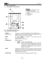
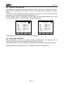
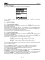
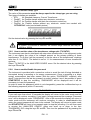
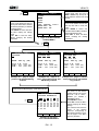
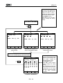
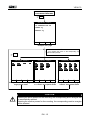
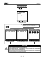
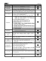
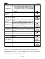
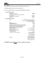
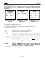
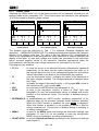
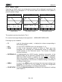
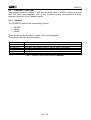
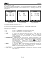
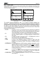
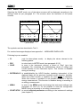
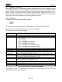
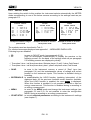
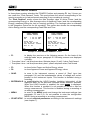
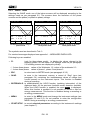
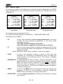
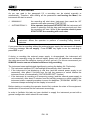
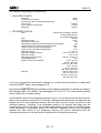
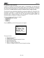
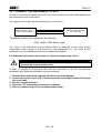
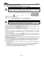
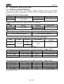
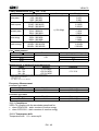
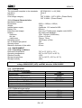
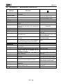
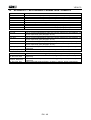
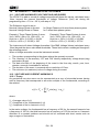
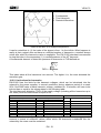
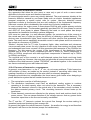
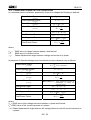
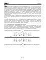
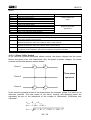


![TSD Series -40C ULT User Manual [EN]](http://vs1.manualzilla.com/store/data/005634658_1-66c9db561a67486106446026c707a26c-150x150.png)