1
Physics Basel
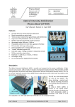
Low Noise / High Resolution DAC
SP 927
User’s Manual
Revision 1.6 (from serial number 0025)
Michael Steinacher | November, 2013
Low Noise / High Resolution DAC
1
Features
Eight DAC voltages with a ±10 V range
Low noise (0.1-100 Hz): Typical 0.5 µVRMS = 3.3 µVPP
24-bit resolution corresponds to a voltage step size of 1.2 µV
Independent DAC channels with a crosstalk isolation of >140 dB
Output ground is isolated from housing and computer interface
LC-display for status display and manual control
Remote controllable via RS-232 or Ethernet (via a web-browser)
LabVIEW drivers included (for RS-232 remote control)
Compact and robust 19” desktop and rack mount housing (2U Height)
Safety Precautions
The Low Noise / High Resolution DAC (LNHR DAC) is designed for indoors dry
laboratory use by qualified and authorized persons only.
Read this manual carefully before installing and use the LNHR DAC; all the safety
precautions must be respected.
Before connecting the device to the mains voltage makes sure that you have the
appropriate power supply module (115 VAC or 230 VAC) attached to the rear side of
the device or properly set the mains section switch (115 VAC / 230 VAC).
Only use a mains power cable with a protection ground (earth). Make sure that the
device is properly grounded.
Always disconnect the mains cable before replacing the mains fuse on the rear side
of the device.
Do not remove any cover. Since the internal parts are precisely adjusted, do not try
to adjust or modify any part of the LNHR DAC.
The external bias voltage must not exceed ±20 V with respect to ground; it is
internally restricted to ±25 V by Zener-Diodes.
When the device is turned off and on again immediately (brown-out), the DAC output
voltages can reach peak levels of up to ±10 Vpeak. Under normal conditions (minimum 10
seconds power-off) almost no spike-voltages (< ±10 mVpeak) occur at the DAC outputs
during power-on or power-off the device.
Disclaimer
Physics Basel hereby disclaims all responsibility for personal injury, property damage
and fine of penalty which results from misuse, not respecting the safety precautions,
improper maintenance or improper application of this product.
Compliance with all applicable environment and personnel safety regulations is the sole
responsibility of the user.
LNHR DAC
User’s Manual - Revision 1.6
Physics Basel
2
Low Noise / High Resolution DAC
1. Description and Applications
The Low Noise / High Resolution DAC (LNHR DAC) generates eight independent, low
noise and ultra-stable voltages. The output range of ±10 V, combined with the 24-bit
resolution, allows adjusting the voltages with a step size of only 1.2 µV. The output
voltage noise is well below 1 µVRMS (typically 0.5 µVRMS), measured in a frequency range
of 0.1 Hz to 100 Hz. Each channel can be independently switched ON (active driven) or
OFF (grounded by 100 kOhm). The device has an alpha numeric display and can be
locally as well as remotely controlled via RS-232 or Ethernet.
Such low noise and ultra-fine tunable voltages are often needed for fundamental physics
experiments at very low-temperatures. For those experiments constant DC bias-voltages
and high resolution sweep-voltages with very low fluctuations (noise) are mandatory;
e.g. for driving gate voltages. Since the typical load resistances of such gates are very
high, the output current of the device is relative small (±1 mA) and the output source
resistance is relative high (500 Ohm).
With an output bandwidth of DC…75 Hz the LNHR DAC can be used for DC-biasing, for
ramping/sweeping and for low frequency waveform generation at high impedance
loads.
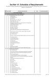
2. Front-Panel
On the left the eight DAC voltages are fed to the front-panel via eight BNC connectors. A
yellow LED above the BNC connector indicates the status (ON/OFF) of the DAC channel.
The large front-panel recesses for the BNC connectors make sure that the outer
conductor doesn’t make an electrical connection to the housing (earth). Make sure that
the outer conductors of your attached BNC cables do not contact the front-panel.
Photo 1: The front-panel of the LNHR DAC with all DAC channel switched on.
The common floating ground of the DAC voltages can be shifted up to ±20 V, with
respect to the housing (earth), by applying an external bias voltage. This bias voltage has
to be connected to the BNC connector (Bias Voltage Input) on the right. Note, when using
this feature the common ground of the DAC outputs is no longer floating and ground
loops may degrade the performance of the device.
On the most right part of the front-panel the LC-display and the rotary/push knob
(encoder) can be found.
LNHR DAC
User’s Manual - Revision 1.6
Physics Basel
3
Low Noise / High Resolution DAC
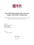
3. Rear-Panel
To minimize the electromagnetic interference from the mains power supply to the DAC
outputs, the transformers and rectifiers are enclosed in an external box attached to the
rear of the LNHR DAC. On the back of this Transformer & Rectifier Housing the mains AC
voltage has to be connected via a standard mains connector plug. Before connecting the
mains voltage makes sure that you have the appropriate power supply module (115 VAC
or 230 VAC) or properly set the mains voltage selection switch (115 VAC / 230 VAC).
Photo 2: The rear-panel of the LNHR DAC with the attached Transformer & Rectifier Housing on
the left.
The mains fuses are installed just to the left of the mains connector. The mains cable
must be disconnected before one can open and replace the mains fuses. The following
slow-blow fuses (d=5 mm, l=20 mm) are needed:
When operating at 115 VAC : 2 x 400 mA; and at 230 VAC: 2 x 200 mA.
One can find the mains power switch between the mains voltage selector switch and the
slot for the fuses. When the power is switched on, almost no spike-voltages (<10 mVpeak)
occur at the DAC outputs. Under brown-out conditions he DAC outputs can reach a peak
level of up to ±10 Vpeak. When the power is switched off, all DAC outputs are switched to
the OFF state immediately and no spikes occur on the DAC outputs.
Photo 3: The external and well shielded Transformer & Rectifier Housing on the rear-panel of the
LNHR DAC prevents from mains-disturbances.
In the middle of the rear-panel, green LEDs indicate when the power is switched on and
when remote writing (DAC values/status) is enabled. Remote reading DAC values/status
is always allowed. During editing DAC values locally, remote writing (via RS-232 or
Ethernet) is disabled.
The connectors for the remote control (RS-232 or Ethernet) are located on the right.
When the LNHR DAC is directly connected to a computer, crossover cables have to be
LNHR DAC
User’s Manual - Revision 1.6
Physics Basel
4
Low Noise / High Resolution DAC
used. For the serial interface (RS-232) a so called “AT link data cable, female-female” has
to be used; such a RS-232 cable with a length of three meters is supplied with the device.
At the top right, a rocker switch allows to select between floating computer interface
and the ground of the interface hard connected to the housing (earth); for more details
see the chapter Grounding.
4. Startup
After the mains power cable is connected and the power switch is turned on (rear side of
the power supply) the device starts up and the following message is displayed on the
LCD:
W E L C O M E
Now starting the
LN/HR DAC software!
(takes about 45 sec)
Note that during power-on the output voltages of the DACs can reach a peak level of up
to ±7 Vpeak. After about 45 seconds the device is ready to run and the following startup
information is shown:
8 Channel Low Noise
High Resolution DAC
Physics Basel
SP 927
During power up all DAC channels are switched OFF and preset to 0 V. After 10 seconds
(or shortened by pressing the push-button) the device displays to the main menu.
5. Main Menu
With the following main menu, several settings can be made locally by using the LCdisplay and the rotary/push knob:
Show/Edit: V/mV
Show/Edit: V/mV/µV
Show/Edit: DEC val.
Show/Edit: HEX val.
HELP
RS-232 Settings
IP Settings
Software Release
Hardware Version
Power Supply Status
Specifications
Restart the device
Contact Information
The main menu can be scrolled up and down by using the rotary knob; a menu item can
be selected by pressing the push-button. Leaving a sub-menu is done by long pressing
the push-button.
LNHR DAC
User’s Manual - Revision 1.6
Physics Basel
5
Low Noise / High Resolution DAC
6. Local Show/Edit DAC Values
By using the four top menu items, the DAC output voltages can be shown and edited in
different number formats. During editing DAC values locally, remote writing a DAC value
is disabled.
In the Show/Edit: V/mV menu all DAC voltages can be displayed/modified on a single
page with a resolution of 1 mV. On the left (separated by a colon) the corresponding
channel number is indicated; the DAC channel 1 and 2 is displayed on the first line, the
DAC channel 3 and 4 on the second line and so on:
12: 10.000V 10.000V
34: <OFF> V <OFF> V
56: -8.000V
3.300V
78:-10.000V -10.000V
The displayed voltages are not measured they are calculated from the set DAC values.
Since the DAC output voltages can have a maximum voltage error of up to ±1 mV, the
shown voltages may be different to the real DAC output voltages.
In the Show/Edit: V/µV menu the DAC voltages can be edited with a resolution of 1 µV.
Since only four channels can be displayed simultaneously, one has to scroll the display
with the rotary knob:
^ 5: -8.000000 V
6:
3.300000 V
7: -10.000000 V
8: -10.000000 V
Because the DAC output voltages can have a maximum voltage error of up to ±1 mV, the
shown voltages may be different to the real DAC output voltages. Due to the intrinsic
DAC resolution of 1.2 µV the last digit (µV) may skip some values due to rounding to the
nearest possible output voltage.
In the Show/Edit: DEC val. menu the decimal DAC values, in a range from 0 (-10 V) to
16’776’960 (+10 V), can be displayed and modified on a single page. The resolution of
the last digit corresponds to a voltage step of 1.2 µV:
12:16776960 16776960
34: <OFF>
<OFF>
56: 1677696 11156678
78:0
0
In the Show/Edit: HEX val. menu the hexadecimal DAC values, in a range from
0x000000 (-10 V) to 0xFFFF00 (+10 V), can be displayed and modified on a single page.
The resolution of the last digit corresponds to a voltage step of 1.2 µV:
12: xFFFF00 xFFFF00
34: x <OFF> x <OFF>
56: x199980 xAA3CC6
78: x000000 x000000
In all the display formats, a DAC channel is switched ON/OFF by double-click the pushbutton; a switched OFF DAC channel is indicated by the text <OFF>.
LNHR DAC
User’s Manual - Revision 1.6
Physics Basel
6
Low Noise / High Resolution DAC
Editing a DAC value is performed manually in this way: First press the push-button, then
a blinking cursor occurs in the left part of the LCD where the DAC channel numbers are
shown. With the rotary knob select the DAC channel to be modified by pressing the
push-button again. Then the blinking cursor jumps to the last digit of the selected DAC
value. Now, select the digit to be in- or decremented with the rotary knob. By pressing
the push-button again the editing-mode gets active.
In the editing-mode the blinking-cursor is replaced by an underline-cursor and the DAC
value is immediately modified by turning the rotary knob left or right. One can toggle
between the digit-selection and the editing-mode just by pressing the button.
Ten seconds after the last user interaction or by long pressing the push-button, the
former selection is retained. The system remains in the editing-mode until the user
presses and holds the push-button long.
7. Local System Settings
The Baud rate of the serial connection can be set in the RS-232 Settings menu item. Baud
rates from to 300 up to 115’200 can be selected by turning the rotary knob. At delivery a
Baud rate of 9600 is programmed. The data length (8 bit), the number of stop-bits (1 stop) and
the parity (none) are fixed and cannot be changed.
Baud rate:
9600
(300-115200 bits/s)
Fix: 8 data, 1 stop
no parity, XON/XOFF
When the Baud rate has been changed by the user and the button is pressed, the device
asks what to do. With the rotary knob one can chose between two options: Escape to
MAIN MENU makes no changes and the old Baud rate remains valid. When choosing
Use/Save Baud Rate! the new Baud rate gets activated and it is saved permanently.
WHAT TO DO NOW?
Escape to MAIN MENU
Use/Save Baud Rate!
Under the menu item IP Settings the IP-address and the subnet-mask of the device can
be programmed. At delivery the private IP-address 192.168.000.005 with a subnet-mask
of 255.255.255.000 is programmed. Setting a different IP-address or a subnet-mask can
be done in the same way as editing a DAC value.
IP-Address:
192.168.000.005
Subnet-Mask:
255.255.255.000
After setting new IP-values and long pressing the push-button the device asks what to
do. With the rotary knob one can select between two options: Escape to MAIN MENU
makes no changes and the old IP-address and subnet-mask remains valid. When
selecting Save IP & Restart! the modified values are saved permanently and the LNHR
DAC is restarted (takes about 45 seconds). Thereafter the new IP-settings are active.
During restarting the device, all DAC channels are switched OFF and they are all reset to
an output voltage of 0 V.
WHAT TO DO NOW?
Escape to MAIN MENU
Save IP & Restart!
LNHR DAC
User’s Manual - Revision 1.6
Physics Basel
7
Low Noise / High Resolution DAC
When selecting the menu item Restart the device the following screen appears:
WHAT TO DO NOW?
Escape to MAIN MENU
Restart the device!
If one confirms to restart the device, the LNHR DAC is restarted (takes about 45 seconds).
During restarting the device, all DAC channels are switched OFF and they are all reset to
an output voltage of 0 V. It the same procedure as the mains power switch was turned OFF
and ON again.
8. Local Information
Different text information can be accessed via the following main menu items (use the
rotary knob to scroll through the long texts):
HELP: General information about the LNHR DAC and the possibilities to control the
device locally and remotely.
Software Release: Shows the installed firmware release and date.
Hardware Version: Displays the serial number of the device and the revisions of the
installed hardware modules.
Power Supply Status: The status of the different power supply voltages is shown
(normally all should be OK):
Line Voltage: OK
+15Va Supply: OK
-15Va Supply: OK
µC Supply
: OK
Specifications: Shows the typical specifications of the LNHR DAC.
Contact Information: Displays the contact information of the manufacturer.
LNHR DAC
User’s Manual - Revision 1.6
Physics Basel
8
Low Noise / High Resolution DAC
9. Remote Control via Serial Port
The device can be controlled remotely via the serial port (RS-232) by using simple ASCII
commands. A crossed null modem AT link data cable (included) has to be used to
connect the device directly to a computer. The Baud rate can be set locally in a range
from 300 Baud up to 115 kBaud via the main menu item RS-232 Settings. At delivery
the baud rate is set to 9'600 bits/sec. The number of data bits is fixed to eight with one
stop bit and the parity is not used. The data flow is controlled via the XON/XOFF
protocol.
To reach fast update rates, use a Baud rate as high as possible. For reliable data transfer
handshaking between the LNHR DAC and the control software is mandatory. Proper
handshaking is implemented in the serial-port LabVIEW drivers, which are included on
a CD at the end of this manual. When operating at the highest Baud rate (115.2 kbit/sec),
typical 175 DAC values per second can be transferred to the LNHR DAC with proper
handshaking. In this case use the following COM-port settings on the host computer:
Make sure that the speed of the serial port
(Baud rate) on the host computer is always the
same as configured on the LNHR DAC (see
chapter 7. Local System Settings).
If this is violated the LNHR DAC firmware may
be blocked and no communication is possible
(also locally). In that case the device has to be
rebooted (power off/on).
During power cycling (on/off) of the host
computer, spurious signals often appear at the
serial output and this may also affect and block
the firmware of the LNHR DAC. Therefore, first
disconnect the connection to the host-computer
before switching it on or off.
To prevent from “Buffer Overrun Error” when using the serial-port LabVIEW drivers in
combination with the maximum Baud rate, use the following advanced settings of your
COM-port installed in the host-computer:
LNHR DAC
User’s Manual - Revision 1.6
Physics Basel
9
Low Noise / High Resolution DAC
All commands must be terminated with a <RETURN>, which can be a Line-Feed <LF> or
Carriage-Return <CR> followed by a Line-Feed <LF>. With a terminal-program send a
"?" followed by a <LF> to the device and you will receive a text with an overview of all
ASCII commands.
All the ASCII commands can be tested simply by using a standard terminal-program (e.g.
HyperTerminal or Putty on Windows systems). The commands are not sensitive to
UPPER and lower case typing. The terminal-program must be configured so that a send
line is terminated with a Line-Feed <LF> or with a Carriage-return and Line-Feed
<CR+LF>; to generate a <LF> with the Putty terminal-program type a CTRL-J. To watch
the typed commands on the computer-monitor, the local echo of the terminal-program
must be turned on.
1) SET COMMANDS:
1.1) SET a DAC-CHannel to a DAC-VALue (HEX):
"DAC-CH[1...8] <SPACE> DAC-VAL(HEX)[0x000000...0xFFFF00] <LF>"
The DAC-VAL(HEX) corresponds to the following voltages:
0x7FFF80 = 0 V
0xBFFF40 = +5 V
0xFFFF00 = +10 V
0x3FFFC0 = -5 V
0x000000 = -10 V
Examples:
SET DAC-CH1 to 0 V: "1 7FFF80<LF>"
SET DAC-CH3 to -2.5 V: "3 5FFFA0<LF>"
SET DAC-CH8 to +3.4 V: "8 AB8473<LF>"
1.1.1) SET ALL DAC-CHannel to a DAC-VALue (HEX):
"ALL <SPACE> DAC-VAL(HEX)[0x000000...0xFFFF00] <LF>"
Examples:
SET ALL DAC-CHannels to 0 V : "ALL 7FFF80<LF>"
SET ALL DAC-CHannels to +10 V: "ALL FFFF00<LF>"
1.2) SET DAC-CHannel STATus (ON or OFF):
"DAC-CH[1...8] <SPACE> STAT[ON/OFF] <LF>"
Examples:
SET DAC-CH1 ON : "1 ON<LF>"
SET DAC-CH5 OFF: "5 OFF<LF>"
1.2.1) SET ALL DAC-CHannel to a STATus (ON or OFF):
"ALL <SPACE> STAT[ON/OFF] <LF>"
Examples:
SET ALL DAC-CHannels ON: "ALL ON"
SET ALL DAC-CHannels OFF: "ALL OFF"
LNHR DAC
User’s Manual - Revision 1.6
Physics Basel
10
Low Noise / High Resolution DAC
When a SET command is received and processed successfully, the device responds with
zero ("0") followed by a <CR+LF>. This “no error” replay must be awaited before the
next SET command can be send. If the SET command cannot be interpreted, an errorcode with a <CR+LF> is returned; the meaning of the error-code is as following:
"0" = No error
"1" = Invalid DAC-CHannel
"2" = Missing DAC-VALue or STATus
"3" = DAC-VALue out of range
"4" = Mistyped
"5" = Remote writing not allowed (local editing is performed)
Up to sixteen SET commands can be combined in a single line by separating the different
commands with a semicolon (";"). For each of the SET commands a separate error-code
is generated (followed by a <CR+LF>).
Example:
SET DAC-CH3 to -5V / DAC-CH3 ON / DAC-CH4 to 0V / DAC-CH8 OFF:
"3 3FFFC0;3 ON;4 7FFF80;8 OFF<LF>"
"0<CR+LF>", "0<CR+LF>","0<CR+LF>","0<CR+LF>"
When using a control-software (automatic sweep etc.), it is strongly recommended to
read and interpret the error-code after each SET command. That results in a save data
transfer with a handshaking between the device and control-software.
2) QUERY DATA COMMANDS:
A QUERY command must be terminated with a question-mark ("?") followed by a <LF>
or a <CR+LF>. Only single QUERY commands can be treated. If a QUERY command
cannot be interpreted, the device response with a question-mark ("?") followed by a
<CR+LF>.
2.1) QUERY a DAC-VALue (HEX) of a DAC-CHannel:
"DAC-CH[1...8] <SPACE> V?<LF>" DAC-VAL(HEX) [0x000000...0xFFFF00]
Examples:
QUERY DAC-VAL of CH1: "1 V?<LF>"
"7FFF80<CR+LF>"
QUERY DAC-VAL of CH8: "3 V?<LF>"
"3FFFC0<CR+LF>"
2.1.1) QUERY ALL DAC-VALues (HEX):
"ALL <SPACE> V?<LF>"
DAC-VAL1; DAC-VAL2;...; DAC-VAL8(HEX) [0x000000...0xFFFF00]
Example:
QUERY ALL DAC-VALues: "ALL V?<LF>"
"7FFF80;7FFF80;3FFFC0;7FFF80;FFFF00;000000;7FFF80;AB8473<CR+LF>"
2.2) QUERY a DAC-STATus (ON or OFF) of a DAC-CHannel:
"DAC-CH[1...8] <SPACE> S?<LF>" STAT [ON/OFF]
LNHR DAC
User’s Manual - Revision 1.6
Physics Basel
11
Low Noise / High Resolution DAC
Examples:
QUERY DAC-STAT of CH1: "1 S?<LF>"
"ON<CR+LF>”
QUERY DAC-STAT of CH8: "3 S?<LF>"
"OFF<CR+LF>"
2.2.1) QUERY ALL DAC-STATus (ON or OFF):
"ALL <SPACE> S?<LF>" -> STAT1;STAT2;...;STAT8 [ON/OFF]
Example:
QUERY ALL DAC-STATus: "ALL S?<LF>"
"ON;OFF;ON;OFF;ON;ON;ON;OFF<CR+LF>"
3) QUERY INFORMATION COMMANDS:
Several text information and settings can be recalled via the serial interface by the
following commands (each query command must be terminated with a <LF> or
<CR+LF>):
"?"
"HELP?”
"SOFT?"
"HARD?"
"POWER?"
"STAT?"
"SPECS?"
"IP?"
"CONTACT?"
Shows an overview of the RS-232 ASCII COMMANDS
Shows the HELP text (as on local LCD)
Shows the software release of the device (as on local LCD)
Shows information to the used hardware (as on local LCD)
Shows the status of the power supply voltages (as on local LCD)
Shows the write status: "0" = Remote writing enabled; "5" = Disabled
Shows the typical specifications of the device (as on local LCD)
Shows the IP-Address and the Subnet-Mask (as on local LCD)
Shows the contact address and further information (as on local LCD)
4) REMARK:
For a given output voltage (Vout[-10 V ...+10 V]) the decimal DAC-Value (DACval
[0...16'776'960]) is given by:
DACval = (Vout + 10) · 838’848
For a given decimal DAC-Value (DACval [0...16'776'960]) the output voltage (Vout
[-10 V...+10 V]) can be determined by:
Vout = (DACval / 838’848) – 10
LNHR DAC
User’s Manual - Revision 1.6
Physics Basel
12
Low Noise / High Resolution DAC
10. Remote Control via Ethernet and TCP/IP
The LNHR DAC can be easily controlled remotely via the Ethernet port (TCP/IP) by
using a web-browser. If the device is directly connected to computer a crossed (X)
network cable has to be used. The IP-address can be set via the menu item IP Settings.
At delivery the IP-address is set to 192.168.0.5 and the subnet-mask to 255.255.255.0.
The embedded web-server allows monitoring and controlling the device with a standard
web-browser. When the web-page is called the first time, the following LabVIEW runtime code is automatically loaded from the National Instruments FTP-server:
ftp://ftp.ni.com/support/labview/runtime/windows/8.6.1/LVRTE861min.exe. In that
case, a second network adapter connected to the internet is needed.
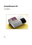
The web-page of the LNHR DAC can be accessed via the web-address:
http://IP-address/LNHR_DAC.html (e.g. http://192.168.0.5/LNHR_DAC.html):
Figure 1: Shows the web remote control panel of the LNHR DAC. Via the web-page the device can be
monitored and DAC values/status can be manually modified.
The upper part of the web-page (READING) shows the actual DAC output voltages and
the status (ON/OFF) of all the DAC outputs. The read DAC values are displayed in voltage
[-10.000000 V…+10.00000 V] as well as in hexadecimal values [0x000000…0xFFFF00].
LNHR DAC
User’s Manual - Revision 1.6
Physics Basel
13
Low Noise / High Resolution DAC
While a DAC value is being locally modified by a user, writing via the web-page (and also
via RS-232) gets disabled. Then the underlying color in the field WRITING changes to red
and all the writing-fields get disabled and greyed-out.
When remote writing is enabled, the color of the WRITING field changes to green. A
button allows toggling between the two different input formats for the DAC values: In
the lower row in hexadecimal values [0x000000…0xFFFF00] and in the upper row in
voltages [-10.000000 V…+10.00000 V].
Without difficulties, the device can be accessed in parallel via RS-232 commands and via
a web-browser. The last written DAC value stays valid until it is changed either via a
RS-232 SET command or via an input from the web-browser. The web-page can be used
to monitor the device during it is remotely controlled via the serial port.
The update rate of the web-page is relative slow (5…10 times/sec) and is not suitable for
fast reading and writing from/to the LNHR DAC.
LNHR DAC
User’s Manual - Revision 1.6
Physics Basel
14
Low Noise / High Resolution DAC
11. Output Noise
The typical DAC output noise voltage of the device is only 0.5 µVRMS which corresponds
to peak to peak noise voltage of about 3.3 µVPP. This RMS-noise is measured in a
frequency band of 0.1 Hz to 100 Hz. The noise has a typical 1/f-frequency characteristic,
that’s why around 80% of the noise is generated in the low frequency band between
0.1 Hz and 10 Hz. The measured noise of your device is appended in the end.
Measuring such low noise levels is quite challenging; short and good cables, low
vibration environment and an elaborated test setup are mandatory. The noise may vary
slightly over time and therefore repeated noise measurements must be averaged (at
least ten = 100 sec) to get a reasonable value. A good portion of the noise is generated
from the ±10 V reference voltages; that’s why the noise at DAC output voltages near zero
is about 30% smaller than at full range (+10 V or -10 V).
Since the noise level is different from device to device, each unit and each channel is
qualified for noise performance after production. The noise is measured at five different
DAC output voltages of 0 V, +5 V, +10V, -5 V and -10 V. Therefore a maximum noise
voltage of 1 µVRMS (6.6 µVPP) averaged over ten sweeps (100 sec) can be guaranteed.
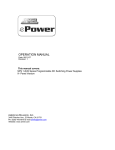
Figure 2: A noise measurement by using a low noise, AC-coupled (fgHP=0.03 Hz), battery powered
preamplifier (SR560) with a gain of 104 and a bandwidth of 100 Hz. This typical noise of 0.5 µVRMS
is measured at a DAC output voltage of -10 V. The upper plot (olive green) shows the time domain
noise signal over 10 second; a peak to peak voltage of around 3.3 µVPP can be registered.
In the lower plot the averaged FFT noise spectra (ocher) and the integrated noise spectra (pink) is
shown in the frequency domain. The integrated RMS-noise from 0.1 Hz up to 180 Hz is exactly
0.5 µVRMS. The noise spectra is generated by using 143 averages (10 sec sweep), which corresponds
to a total measuring time of almost 25 minutes. The unavoidable mains frequency (50 Hz) and its
third harmonics (150 Hz) can clearly be identified in the noise spectra.
LNHR DAC
User’s Manual - Revision 1.6
Physics Basel
15
Low Noise / High Resolution DAC
12. Grounding
To prevent ground loops and interferences, the DAC output voltages are referred to a
common ground which is galvanic-isolated from the housing (earth) and from the
computer interface. The common DAC output ground can be shifted by up to ±20 V with
respect to the housing (earth). The ground reference of the DAC outputs is connected to
the experiment (e.g. cryostat) via the shields of the BNC cables. Due to the galvanicisolation, no troublesome ground loop currents can flow over the shielding of the cables.
If external AC magnetic fields are present, loop currents can be induced in shields of the
eight BNC cables running from the DAC to the experiment. To minimize this effect, bring
the BNC cables as close as possible or, even better, twist them.
In addition the computer interface is also galvanic-isolated from the housing (earth) and
it can also be shifted by up to ±20 V with respect to the housing (earth). A switch on the
rear side of the device allows the user to select the computer interface between floating
or grounded. For electrostatic reason, also in the floating mode, the ground of the
computer interface is connected via a 100 kOhm resistor to the housing (earth).
With this grounding concept, no optically isolated computer interfaces are needed also
in very sensitive experimental environment.
Figure 3: The block diagram of the LNHR DAC and its grounding principle. If the external bias
voltage input is left open, the common ground of the DAC outputs is floating with respect to the
housing (earth) and the computer interfaces. By driving the external bias voltage, the ground of the
DAC outputs can be shifted by up to ±20 V with respect to the housing (earth).
LNHR DAC
User’s Manual - Revision 1.6
Physics Basel
Low Noise / High Resolution DAC
16
13. Typical Specifications (Temperature 25 °C, 4 h warm-up)
Independent DAC output channels: 8
Output voltage range: ±10 V
Output current: max. : ±1 mA
Resolution: 24-bit (LSB equal to 1.19 µV)
Absolute voltage error: typ. ±200 µV; max. ±1 mV
Offset voltage error (@ Vout = 0 V): typ. ±100 µV ; max. ±500 µV
Integral nonlinearity (INL): ±80 LSB
Drift over 8 h (T = constant 25 °C): ±10 µV
DAC output voltage during power-on (@power-off min. 10 sec): < ±10 mVpeak
DAC output voltage during fast power-on/off (brown-out): max. ±10 Vpeak
ON output source impedance: 500 Ohm // 1.2 µF
OFF output impedance to GND: 100 kOhm // 1.2 µF
Output bandwidth: 75 Hz
Overshoot (0 V to +10 V Step): typ. 0.6%, max. 1.2%
Rise-time (10% to 90%): 4.7 ms
Settling time for an error < 0.1%: 18 ms after “no error” echo is received
Noise (0.1 Hz...100 Hz): typ. 0.5 µVRMS (3.3 µVpp); max. 1 µVRMS (6.6 µVpp)
DAC output ground is common for all channels and it is galvanic-isolated from
housing (earth) and from the computer interface (RS-232 and Ethernet).
Channel to channel crosstalk isolation: >140 dB
Bias voltage (DAC output ground to housing/earth): max. ±20 V
Capacitance of DAC output ground to housing (earth): 1.5 nF
Computer interface ground to housing (earth) voltage: max. ±20 V
Capacitance of computer interface ground to housing (earth): 1 nF
Warm-up time: 4 h
Mains voltage supply: 115 VAC / 230 VAC (both +10%, -5%) 50…60 Hz
Mains power consumption: typ. 25 W, max. 30 W
DAC update rate (via RS-232 @115 kBaud): 175 DAC values per second
Housing: 19” width for tabletop use or rack-mount
Housing dimensions: Width 480 mm, Height 100 mm (2U), Depth 430 mm
Weight: 8 kg (17.7 lb)
14. Operation Conditions
Environment: Indoors dry laboratories only!
Ambient temperature between 10 °C ( 50 °F) and 40 °C (104 °F)
Altitude up to 2’000 m (6’561 ft).
Maximum relative humidity 80% for temperatures up to 31 °C (88 °F), decreases
linearly to 50% at a temperature of 40 °C (104 °F).
Pollution degree 1 (no pollution or only dry and non-conductive pollution).
LNHR DAC
User’s Manual - Revision 1.6
Physics Basel
17
Low Noise / High Resolution DAC
15. Background
The enormous resolution of 24-bit is reached by applying a pulse-width modulation
(PWM) on the least significant bit (LSB) of a commercially available 16-bit DAC-chip
(Texas Instruments DAC8871). To eliminate the parasitic PWM fundamental frequency
of 919 Hz, the voltage output of the DAC-chip is filtered by a low-pass Bessel filter (f-3dB =
75 Hz), designed for low noise performance.
To reach the low noise performance of the LNHR DAC, the reference voltages (±10 Vref)
supplied to the DAC-chip is crucial. To minimize this noise source, pretested and
selected low noise voltage reference-chips are used in this device. For further reducing
the noise, by around a factor of two, four of these selected low noise voltage referencechips are combined.
To increase the linearity, a calibration procedure is accomplished on each DAC output
after production. This is done by using a precision, stable and high resolution digital
voltmeter (Keithley 2010) as reference. 2’000 interpolation voltages between -10 V and
+10 V are measured and then the linearity error versus DAC value is fit by a high order
polynomial correction function. The determined polynomial linearization coefficients
are then transferred and saved onto the LNHR DAC.
The 16-bit DAC-chip has a typical integral nonlinearity (INL) of ±1 LSB, which
corresponds to ±256 LSB in the 24-bit system of the LNHR DAC. Through the calibration
process the INL is reduced by a factor of around three to typical ±80 LSB.
All internal supply voltages are supervised. If one fails, all DAC outputs are immediately
switched OFF. This makes sure that no erroneous DAC output voltage can occur, which
could damage sensitive samples attached to the LNHR DAC.
A sbRIO board (9602) from National Instruments is used to control the LNHR DAC and it
enables the remote control of the output voltages via Ethernet (TCP/IP) and the serial
port (RS-232). Also the error corrections for the DAC-chips are calculated in real-time
(RT), based on the stored polynomial linearization coefficients. The web-server, running
on the RT-processor of the sbRIO board, allows monitoring and controlling of the eight
output voltages by using a normal web browser. Further a LC-display (4 x 20 characters)
and a rotary/push knob allow the local control and setup of the device by the user.
The FPGA on the sbRIO board performs the time critical SPI-bus communication with
the eight independent DAC boards and it manages the pulse-width modulation of the
LSB to increase the resolution of the DAC-chips to 24-bit. Further some low-level
routines for driving the LCD and reading the rotary/push knob are also implemented in
the FPGA.
The programming of the LNHR DAC is carried out by using the LabVIEW FPGA Module,
the LabVIEW RT Module and the RT State-Chart Module. The FPGA-program is
structured in about 20 Sub-VIs and the RT-code covers around 100 Sub-VIs.
LNHR DAC
User’s Manual - Revision 1.6
Physics Basel