1
23
7.4 CAPTURING FLUORESCENCE IMAGES
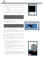
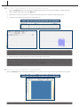
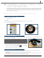
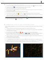
1. To acquire images make sure that the light path selector lever is switch on the DP71 camera (
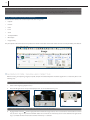
2. f not pressed, select the
) mode, see sec. 7.2, step d.
in the capture mode to display the image record window.
3. Remove the BF light source and turn on the fluorescence light source.
4. Disable shutter (move to ), to enable light from the fluorescence light source. The shutter can be found in the fluorescence
mirror unit, as seen in Fig. 7 6.
5. Select desired excitation/emission filter for capturing fluorescence images.
6. Turn off the laser by clicking the button
so it changes into
in the hardware parameters panel (Nova software).
7. Used the focus adjustment knob to focus onto the sample. When the 60x objective has been mounted only use the fine
adjustment knob to focus after immersion oil has made contact to sample.
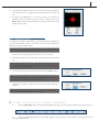
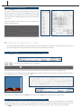
Notice: To aid focusing full screen can be utilized. This is done by pressing
8. Capture the image by pressing
in the software top panel.
in the capture mode.
7.5 COMBINING AFM TOPOLOGY AND FLUORESCENCE IMAGE
At this state both the NTEGRA Life and Olympus IX71 should be fully operational and the probe, sample and objective should be
aligned.
1. To obtain optimal superimposed AFM and fluorescence images the 60x objective should be mounted.
2. The BF light source should be used to locate a desired scan area on the sample and an image should be captured before
switching to fluorescence imaging.
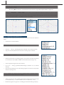
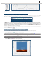
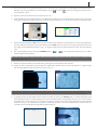
3. Turn off the laser by clicking the Laser button
/
in the Hardware Parameters panel (Nova software).
4. Turn off the feedback system by clicking the FeedBack button
/
in the Hardware Parameters panel (Nova
software). This retracts the probe, so that a desired sample area can be selected and inspected before proceeding.
5. Switch to excitation by the fluorescence light source and acquire a fluorescence image of the selected sample area. See sec. 7.4
for further introduction to acquiring images.
6. Turn on both laser and feedback system again.
7. An initial AFM topology should be produced in a size several fold larger than the expected size of the investigated specimens.
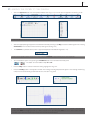
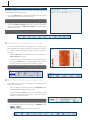
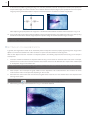
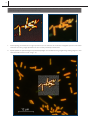
8. Manually compare the produced AFM and captured fluorescence images, to locate the AFM topology in the corresponding
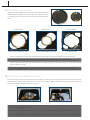
fluorescence image of the selected sample area. Such a comparison could result in the images shown in Fig. 7 17.
FIG. 7-17
FIG. 7-18