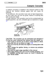
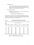
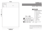
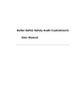
1
www.garyklinka.com
1 of 19
RECIRCULATING SAND FILTER SYSTEM COMPONENT QUIZ
12 Hours of CEU credits for the following credentials:
Powts Maintainer
Powts Restricted Technology Installer registration
Powts Inspector
Journeyman Plumber-Restricted Service
Journeyman Plumber
Fee $99.00
Qualifier Powts Maintainer
Soil Tester
Master Plumber-Restricted Service
Master Plumber
Instructions:
www.garyklinka.com
1. Print these pages.
2. Circle the correct answers and transfer to the answer sheet on the last page.
3. Page down to the last page for the verification forms and mailing instructions.
4. Download Manual-Click Here
1.
2.
3.
4.
5.
INFLUENT FLOWS AND LOADS
Table 1
The design wastewater flow (DWF) from one and two-family dwellings must be?
A. < 2250 gal/per day
B. < 150 gal/day/bedroom
C. = Design wastewater flow (DWF)
D. 150% of estimated wastewater flow in accordance with Table 4 of this manual or s.
Comm 83.43 (6), Wis. Adm. Code
The design wastewater flow (DWF) from primary treatment tanks must be?
A. < 2250 gal/per day
B. < 150 gal/day/bedroom
C. = Design wastewater flow (DWF)
D. 150% of estimated wastewater flow in accordance with Table 4 of this manual or s.
Comm 83.43 (6), Wis. Adm. Code
The design wastewater flow (DWF) from public facilities must be?
A. < 2250 gal/per day
B. < 150 gal/day/bedroom
C. = Design wastewater flow (DWF)
D. >150% of estimated wastewater flow in accordance with Table 4 of this manual or s.
Comm 83.43 (6), Wis. Adm. Code
The Forward flow must be?
A. < 2250 gal/per day
B. < 150 gal/day/bedroom
C. = Design wastewater flow (DWF)
D. >150% of estimated wastewater flow in accordance with Table 4 of this manual or s.
Comm 83.43 (6), Wis. Adm. Code
Distribution cell area per orifice size for a sand filter media tank must be?
A. ≤ 2250 gal/per day
B. ≤ 4 ft²
C. ≥ 4 ft²
D. ≤6 ft²
www.garyklinka.com
6. Design loading rate (DLR) for a sand filter media tank must be?
A. ≤ 5 gpd/ft2 based on forward flow
B. ≤ 4 ft²
C. ≥ 5 gpd/ft2 based on forward flow
D. ≤6 ft²
Table 2 SIZE
7. Surge volume in recirculation tank or chamber must be?
A. ≥ Depth as required by pump manufacturer
B. ≥ 2.2 x DWF
C. ≥ 2/3 DWF
D. ≥ DWF ÷ 2
8. Reserve volume in recirculation tank or chamber must be?
A. ≥ Depth as required by pump manufacturer
B. ≥ 2.2 x DWF
C. ≥ 2/3 DWF
D. ≥ DWF ÷ 2
9. Recirculation tank capacity must be?
A. ≥ Depth as required by pump manufacturer
B. ≥ 2.2 x DWF
C. ≥ 2/3 DWF
D. ≥ DWF ÷ 2
10. Pump protection volume capacity in recirculation tank or chamber
A. ≥ Depth as required by pump manufacturer
B. ≥ 2.2 x DWF
C. ≥ 2/3 DWF
D. ≥ DWF ÷ 2
11. Orifice spacing along lateral for a sand filter media tank must be?
A. ≥ 37 inches
B. ≥ DWF DLR
C. ≤ 24 inches
D. ½ of spacing between laterals or 12 inches, whichever is less
12. Total distribution cell area for a sand filter media tank must be?
A. ≥ 37 inches
B. ≥ DWF DLR
C. ≤ 24 inches
D. ½ of spacing between laterals or 12 inches, whichever is less
13. Depth of filter tank for a sand filter media tank must be?
A. ≥ 37 inches
B. ≥ DWF DLR
C. ≤ 24 inches
D. ½ of spacing between laterals or 12 inches, whichever is less
14. Spacing between laterals for a sand filter media tank must be?
A. ≥ 37 inches
B. ≥ DWF DLR
C. ≤ 24 inches
D. ½ of spacing between laterals or 12 inches, whichever is less
2 of 19
www.garyklinka.com
3 of 19
Table 3 OTHER SPECIFICATIONS
15. Depth of stone aggregate over effluent distribution network must be?
A. ≥ 3 inches
B. ≥ 24 inches
C. ≥ 2 inches
D. ≥ 2 to ≤ 6 inches
E. ≥ 6 inches
16. Depth of filter media must be?
A. ≥ 3 inches
B. ≥ 24 inches
C. ≥ 2 inches
D. ≥ 2 to ≤ 6 inches
E. ≥ 6 inches
17. Depth of stone aggregate under a effluent distribution network must be?
A. ≥ 3 inches
B. ≥ 24 inches
C. ≥ 2 inches
D. ≥ 2 to ≤ 6 inches
E. ≥ 6 inches
18. Depth of pea gravel over underdrain pipe must be?
A. ≥ 3 inches
B. ≥ 24 inches
C. ≥ 2 inches
D. ≥ 2 to ≤ 6 inches
E. ≥ 6 inches
19. Depth of stone aggregate for underdrain effluent collection must be?
A. ≥ 3 inches
B. ≥ 24 inches
C. ≥ 2 inches
D. ≥ 2 to ≤ 6 inches
E. ≥ 6 inches
20. Stone aggregate sieve specifications must be?
A. ≥ Two 4 inch pipes extending from the filter media aggregate interface to
finished grade
B. Located at a distance equal to approximately 1/6 the distribution cell
length from each end along the center of the filter’s width
C. ≥ 5 feet
D. ≤ 10%
E. ≤ 15%
F. Aggregate Maximum/minimum Gradation (ASTM Standard C33, Size 4, coarse aggregate)
21. Difference in flow between any two orifices in the effluent distribution network would be?
A. ≥ Two 4 inch pipes extending from the filter media aggregate interface to finished grade
B. Located at a distance equal to approximately 1/6 the distribution cell length from each end along
the center of the filter’s width
C. ≥ 5 feet
www.garyklinka.com
22.
23.
24.
25.
4 of 19
D. ≤ 10%
E. ≤ 15%
F. Aggregate Maximum/minimum Gradation (ASTM Standard C33, Size 4, coarse aggregate)
Difference in flow between any two orifices in a single lateral
A. ≥ Two 4 inch pipes extending from the filter media aggregate interface to finished grade
B. Located at a distance equal to approximately 1/6 the distribution cell length from each end along
the center of the filter’s width
C. ≥ 5 feet
D. ≤ 10%
E. ≤ 15%
F. Aggregate Maximum/minimum Gradation (ASTM Standard C33, Size 4, coarse aggregate)
Head pressure on orifice must be?
A. ≥ Two 4 inch pipes extending from the filter media aggregate interface to finished grade
B. Located at a distance equal to approximately 1/6 the distribution cell length from each end along
the center of the filter’s width
C. ≥ 5 feet
D. ≤ 10%
E. ≤ 15%
F. Aggregate Maximum/minimum Gradation (ASTM Standard C33, Size 4, coarse aggregate)
Location of observation pipes must be?
A. ≥ Two 4 inch pipes extending from the filter media aggregate interface to finished grade
B. Located at a distance equal to approximately 1/6 the distribution cell length from each end along
the center of the filter’s width
C. ≥ 5 feet
D. ≤ 10%
E. ≤ 15%
F. Aggregate Maximum/minimum Gradation (ASTM Standard C33, Size 4, coarse aggregate)
Number of observation pipes must be?
A. ≥ Two 4 inch pipes extending from the filter media aggregate interface to finished grade
B. Located at a distance equal to approximately 1/6 the distribution cell length from each end along
the center of the filter’s width
C. ≥ 5 feet
D. ≤ 10%
E. ≤ 15%
F. Aggregate Maximum/minimum Gradation (ASTM Standard C33, Size 4, coarse aggregate)
DEFINITIONS
26. Defines a valve that opens to allow effluent from the filter media to be discharged totally to the
recirculation tank during low or no wastewater flow conditions.
A. By-pass valve
B. By-pass zone
C. Infiltrative surface
D. Recirculation rate
E. Recirculating sand filter system
F. Recirculation tank
www.garyklinka.com
5 of 19
27. Defines a volume of liquid in a recirculation tank that is designed to provide the filter with sufficient
liquid to keep the filter active when the recirculation tank is receiving little or no flow from a facility.
A. By-pass valve
B. By-pass zone
C. Infiltrative surface
D. Recirculation rate
E. Recirculating sand filter system
F. Recirculation tank
28. Defines a top layer of media that receives effluent from a distribution network.
A. By-pass valve
B. By-pass zone
C. Infiltrative surface
D. Recirculation rate
E. Recirculating sand filter system
F. Recirculation tank
29. Defines the portion of the wastewater effluent that is delivered back into the system compared
to the wastewater effluent that is not delivered back into the system.
A. By-pass valve
B. By-pass zone
C. Infiltrative surface
D. Recirculation rate
E. Recirculating sand filter system
F. Recirculation tank
30. Defines an onsite wastewater treatment component, which contains a recirculation tank and an
effluent filtering component which treats wastewater bypassing it through the system more than once.
A. By-pass valve
B. By-pass zone
C. Infiltrative surface
D. Recirculation rate
E. Recirculating sand filter system
F. Recirculation tank
31. Defines the tank which receives effluent from a septic treatment tank and sand filter and doses the sand
filter.
A. By-pass valve
B. By-pass zone
C. Infiltrative surface
D. Recirculation rate
E. Recirculating sand filter system
F. Recirculation tank
III. DESCRIPTION AND PRINCIPLE OF OPERATION
32. POWTS recirculating sand filter system component operation consists of a recirculation tank or chamber
and a fixed film aeration process unit in which wastewater passes through a porous media.
A. true
B. false
33. Oxygen diffuses into the thin film of vapor as air passes through the media by convection due to
temperature differences.
www.garyklinka.com
6 of 19
A. true
B. false
34. The filter is of such coarse material, that orifices may only cover forty square feet of surface area.
A. true
B. false
35. Physical entrapment, increased retention time, and conversion of pollutants in the wastewater are
important treatment objectives accomplished under unsaturated conditions.
A. true
B. false
Figure 1 indicates the flow path of a recirculating sand filter system.
Use diagram for questions 36-40
36. Letter ‘a’ represents
37. Letter ‘b’ represents
38. Letter ‘c’ represents
39. Letter ‘d’ represents
40. Letter ‘e’ represents soil
IV DESIGN
41. Recirculating Sand Filter System Component Design – Detailed plans and specifications must be
developed, reviewed and approved by the governing unit having authority over the plan for the installation.
A Sanitary Permit must also be obtained from the department or governmental unit having jurisdiction.
A. true
B. false
42. Design of the recirculating sand filter system component is based on the estimated wastewater flow. It
must be sized such that it can accept the daily wastewater flow at a rate that will provide treatment.
A. true
B. false
www.garyklinka.com
7 of 19
43. One and two-family dwellings. The infiltrative surface size for one and two-family dwelling application
is determined by calculating the designed wastewater flow (DWF).
A. true
B. false
Step B. Design of the Recirculation Tank or Chamber
44. This section determines the required liquid capacity and depth of the recirculation tank or chamber as
well as the operation elevation of the by-pass valve, high water alarm and low level emergency pump cut off.
A. true
B. false
Use for questions 45-54
45. Letter ‘a’ represents
46. Letter ‘b’ represents
47. Letter ‘c’ represents
48. Letter ‘d’ represents
49. Letter ‘e’ represents
50. Letter ‘f’ represents
51. Letter ‘g’ represents
52. Letter ‘h’ represents
53. Letter ‘i’ represents
www.garyklinka.com
8 of 19
54. Letter ‘j’ represents
55. Minimum liquid capacity of recirculation tank or chamber = 2.2 x DWF
A. true
B. false
56. Gallons per inch of tank or chamber = capacity in gallons × liquid depth in inches.
A. true
B. false
57. The volume of a single dose is determined by multiplying the 2/3 of the DWF by the recirculation rate
then dividing by the number of doses per day. Number of doses per week must between 24 and 48.
A. true
B. false
58. Reserve zone capacity = DWF × 2
A. true
B. false
59. Elevation at which the by-pass valve opens = Elevation required in the tank to hold a volume of liquid
equal to the DWF
A. true
B. false
60. The minimum elevation of the inlet invert is determined by dividing the sum of the required volumes of
the by-pass valve zone, surge zone, and reserve zones by the gallons per inch value of the tank.
A. true
B. false
Step C. Design of the Recirculating Sand Filter Component
Fig. 3 – Formed sand filter
Use diagram for question 61-73
www.garyklinka.com
9 of 19
61. Letter ‘a’ represents
62. Letter ‘b’ represents
63. Letter ‘c’ represents
64. Letter ‘d’ represents
65. Letter ‘e’ represents
66. Letter ‘f’ represents
67. Letter ‘g’ represents
68. Letter ‘h’ represents
69. Letter ‘i’ represents
70. Letter ‘j’ represents
71. Letter ‘k’ represents
72. Letter ‘l’ represents
73. Letter ‘m’ represents
Fig. 4 – Sand filter in a tank
Use diagram for question 74-77
www.garyklinka.com
10 of 19
74. Letter ‘a’ represents
75. Letter ‘b’ represents
76. Letter ‘c’ represents
77. Letter ‘d’ represents
Fig. 4 – Sand filter in a tank
Use diagram for question 78-84
78. Letter ‘e’ represents
79. Letter ‘f’ represents
80. Letter ‘g’ represents
81. Letter ‘h’ represents
82. Letter ‘i’ represents
83. Letter ‘j’ represents
84. Letter ‘k’ represents
85. The minimum distribution cell area is calculated by dividing the design wastewater flow by a design
loading rate of 5gpd/ft2.
A. true
B. false
www.garyklinka.com
11 of 19
86. The sand filter container is a watertight closed top vessel.
A. true
B. false
87. A 4” underdrain pipe with slots or holes is placed on the bottom of the container to collect the filtered
effluent. Installation orientation of the slots or holes must be on the bottom of the underdrain pipe. The
collection pipe extends outside the sand filter container to the recirculation tank.
A. true
B. false
88. A layer of stone aggregate meeting the specifications listed in Table 1 is placed in the bottom of the tank
to a depth of at least equal to the bottom of the collection pipe. The stone aggregate provides a means for the
filtered effluent to flow to the collection pipe.
A. true
B. false
89. A layer of pea gravel meeting the specifications listed in Table 3 is placed over the effluent collection
stone aggregate and filtered effluent collection pipe to a depth of at least three inches. The pea gravel acts a
barrier so the filter media does not migrate into the collection stone aggregate and pipe.
A. true
B. false
90. A three-foot layer of sand media meeting the specifications listed in Table 1 is placed on top of the pea
gravel to provide filtration and treatment of the effluent. The top of the filter media is leveled.
A. true
B. false
91. The distribution network spreads the septic tank effluent as uniformly as possible over the sand filter
surface. The network consists of a manifold and laterals. Typical design consists of:
A. Orifices - orifices shall be located upward with orifice shields or a half pipe
protecting the orifices from becoming blocked by aggregate.
B. Laterals – laterals are spaced two feet apart, with an upturned long sweep
elbow and valve for clean out. The lateral length can not exceed that indicated in
Graph 1 for various diameters. Laterals are sloped back in order to provide
drainage of the lateral between doses.
C. Manifold – manifolds slope back to provide drainage of the manifold between doses.
The manifold is sized using Table 5.
D. all of the above.
92. The distribution network spreads the septic tank effluent as uniformly as possible over the sand filter
surface. The network consists of a manifold and laterals. Typical design consists of:
A. Force main – Force mains slope back to provide drainage of the force main
between doses. The force main is sized using Table 6.
B. Recirculation tank pump - the pump is sized to meet flow rate and lateral
pressure of at least five feet at distal end.
C. both A & B
D. A only
E. B only
www.garyklinka.com
Graph 1
Minimum Lateral Diameter Based on Orifice Spacing for 1/8" Diameter Orifices
Use below diagram for question 93-98
93. Letter ‘a’ represents
94. Letter ‘b’ represents
95. Letter ‘c’ represents
96. Letter ‘d’ represents
96. Letter ‘e’ represents
97. Letter ‘f’ represents
98. Letter ‘g’ represents
12 of 19
www.garyklinka.com
Table 5
Maximum Manifold Length Based on Individual Lateral Flow Rates
Use below diagram for questions 99-106
99. Letter ‘a’ represents
100. Letter ‘b’ represents
101. Letter ‘c’ represents
102. Letter‘d’ represents
103. Letter ‘e’ represents
104. Letter ‘f’ represents
105. Letter ‘g’ represents
106. Letter ‘h’ represents
13 of 19
www.garyklinka.com
14 of 19
Table 6
Friction Loss (foot/100 feet) in Plastic Pipe
Use below diagram for questions 107-113
107. Letter ‘a’ represents
108. Letter ‘b’ represents
109. Letter ‘c’ represents
110. Letter‘d’ represents
111. Letter ‘e’ represents
112. Letter ‘f’ represents
113. Letter ‘g’ represents
114. At least ____ observation pipes are placed extending from the top of the filter media/stone aggregate
interface to finish grade to monitor for ponding and/or formation of a clogging mat.
A. 1
B. 2
C. 3
D. 4
www.garyklinka.com
15 of 19
115. The pipes must be secured and have perforations in the bottom ____ inches.
A. 1
B. 2
C. 3
D. 4
Fig. 5 – Observation pipes
Use diagram below for question 116-123
116. Letter ‘a’ represents
117. Letter ‘b’ represents
118. Letter ‘c’ represents
119. Letter‘d’ represents
120. Letter ‘f’ represents
121. Letter ‘g’ represents
122. Letter ‘h’ represents
123. The sand filter effluent drains by gravity through the recirculation tank. The filtered effluent drain pipe
is installed with a means of diverting 55 to 65% of the effluent to the recirculation tank and with a low liquid
level by-pass valve to divert all of the effluent into the recirculation tank during low or no flow conditions.
A. true
B. false
124. The filtered effluent drain pipe diverts 55 to 65% of the effluent into the recirculation tank by the use of
a special flow splitter fitting.
A. true
B. false
www.garyklinka.com
16 of 19
Fig. 6 – Flow splitter fitting using pipe fittings
Use below diagram for questions 125-
125. Letter ‘a’ represents
126. Letter ‘b’ represents
127. Letter ‘c’ represents
128. Letter ‘d’ represents
129. Letter ‘e’ represents
130. Letter ‘f’ represents
131. Letter ‘g’ represents
132. The pipe connecting the by-pass valve to the discharge pipe is installed on the discharge side of the
flow control fitting by the use of a short turn tee fitting.
A. true
B. false
Fig. 8 – By-pass valve using float ball
Use below diagram for questions 133-138
www.garyklinka.com
17 of 19
133. Letter ‘a’ represents
134. Letter ‘b’ represents
135. Letter ‘c’ represents
136. Letter ‘d’ represents
137. Letter ‘e’ represents
138. Letter ‘f’ represents
Fig. 9 – By-pass valve using float valve
Use below diagram for questions 139-145
139. Letter ‘a’ represents
140. Letter ‘b’ represents
141. Letter ‘c’ represents
142. Letter ‘d’ represents
143. Letter ‘e’ represents
144. Letter ‘f’ represents
145. The cover over the distribution net work must extend to final grade and be of either wash aggregate or
decorative rock. All surface waters must be diverted away from the sand filter.
A. true
B. false
146. The sand filter is dosed by timed doses. The recirculation tank or chamber must provide for surge
loading and surge (forward) volumes.
A. true
B. false
www.garyklinka.com
18 of 19
147. The excavation for a recirculating sand filter is made 6” to 12” larger than the filter. Untreated
plywood, wafer board or other suitable material is formed into a box to support the liner and allow the liner
to be draped over the top. Only sand is placed between the frame and soil to protect the liner after the
plywood has decomposed. Approximately 1” of sand is placed in the bottom of the excavation prior to
placement of the liner. The top of the liner must be above the seasonal high water table so groundwater does
not flow into the sand filter.
A. true
B. false
148. Recirculating sand filter system. Install a four inch diameter underdrain filtered effluent collection pipe
with slots or holes by placing it on the bottom of the sand filter tank and connecting it to solid wall pipe prior
to exiting the tank. The installation orientation of the slots or holes must be on the side of the underdrain
pipe. The opening in the tank wall shall be sealed by use of a gasket.
A. true
B. false
149. The component owner is responsible for the operation and maintenance of the system. The county,
department or POWTS service contractor shall make periodic inspections of the components, and effluent
levels, etc.
A. true
B. false
150. Design approval and site inspections before, during, and after the construction are accomplished by the
county or other appropriate jurisdictions in accordance to Comm 83 of the Wis. Adm. Code.
A. true
B. false
151. The septic and recirculation tanks are to be inspected and maintained at least every three years. If the
scum and sludge occupies 1/3 of the tanks’ volume, the tank shall be pumped and its contents properly
disposed of. If the tank is not pumped at this time, it shall be pumped when the scum and sludge occupies 1/3
of the tanks’ volume.
A. true
B. false
152. Inspections of recirculating sand filter component performance is required at least every six months for
the first two years. Then once a year for the next two years. Then once every three years, thereafter. These
inspections include checking the liquid levels in the observation pipes and examination for any seepage
around the filter.
A. true
B. false
153. User’s Manual: A user’s manual is to accompany the recirculating sand filter component. The manual
is to contain the following as a minimum:
A. Diagrams of all system components and their location.
B. Specifications for electrical and mechanical components.
C. Names and phone numbers of local health authority, component manufacturer or management
entity to be contacted in the event of a failure.
D. Information on the periodic maintenance of the recirculating sand filter system, including
electrical and mechanical components.
E. none of the above
F. all of the above
www.garyklinka.com
19 of 19
To obtain your Continuing Education Credits follow the below instructions.
1.
2.
3.
4.
Click on course, print out, circle answers, mail in the course only & keep the manual.
Fill in all fields applicable.
Include your certification or license number.
We’ll take care of crediting with the state and mailing back to you the quiz results.
Send by mail
1.
2.
3.
4.
5.
6.
www.garyklinka.com
Answer sheets.
Fee $99.00
Fill out this form below completely.
Applicable fees by check payable to Gary Klinka.
Mail to: Gary Klinka at 228 Mandella Ct Neenah WI 54956.
Questions: office 920-727-9200 fax 888-727-5704 including Saturday and Sundays.
Cell 920-740-4119 or 920-740-6723 & by email [email protected]
-------------------------------Educational Course Attendance Verification Form --------------------------------Attendee’s Name
Date
Address
Credential Number
Course Title and Name
Phone#
Sand Filter Quiz
Fax#
List the name of each credential held by attendee
Credited Hours
12 hours
Fee $99.00
Email
------------------------------------------------------------------------------------------------------------------------------To be completed by Gary Klinka
Course Password
My credential link #70172
Course ID#
Attendee passed the course with a greater than 70% score on Date
Instructor Signature
8305