1
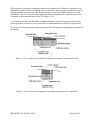
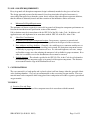
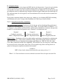
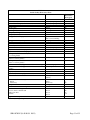
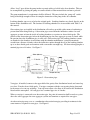
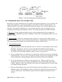
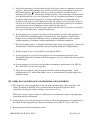
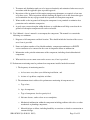
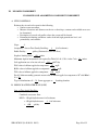
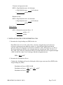
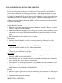
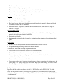
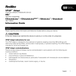
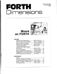
IN-GROUND SOIL ABSORPTION COMPONENT MANUAL FOR
PRIVATE ONSITE WASTEWATER TREATMENT SYSTEMS
(VERSION 2.0)
October 2012
State of Wisconsin
Department of Safety & Professional Services
Division of Safety and Buildings
SBD-10705-P (N. 01/01; R. 10/12)
Page 1 of 32
IN-GROUND SOIL ABSORPTION COMPONENT MANUAL
FOR PRIVATE ONSITE WASTEWATER TREATMENT SYSTEMS
TABLE OF CONTENTS
Page
I.
Introduction and Specifications
3
II.
Definitions
9
III.
Description and Principle of Operation
9
IV.
Soil and Site Requirements
11
V.
Cover Material
11
VI.
Design
11
VII.
Site Preparation and Construction
19
VIII.
Operation, Maintenance and Performance Monitoring
20
IX.
References
22
X.
In-ground Worksheet
23
XI.
Example Worksheet
26
XII.
Plan submittal and Installation Inspection
29
Republished on October 2012 by Department of Safety & Professional Services
(Published on January 2001 by Dept. of Commerce)
Division of Safety and Buildings
Safety and Buildings Publication SBD-10705-P (N.01/01; R. 10/12)
ADA Statement
The Department of Safety & Professional Services is an equal opportunity service provider and
employer. If you need assistance to access services or need material in an alternate format, please
contact the Department at (608) 266-3151. Deaf, hearing or speech-impaired callers may reach the
Department through WI-TRS (Wisconsin Telecommunication Relay System).
SBD-10705-P (N. 01/01; R. 10/12)
Page 2 of 32
I. INTRODUCTION AND SPECIFICATIONS
This Private Onsite Wastewater Treatment System (POWTS) component manual provides design,
construction, inspection, operation, and maintenance specifications for an in-ground soil absorption
component. However, these items must accompany a properly prepared and reviewed plan acceptable
to the governing unit to help provide a system that can be installed and function properly. Violations of
this manual constitute a violation of chs. SPS 383 and 84, Wis. Adm. Code. The in-ground soil
absorption component must receive influent flows and loads less than or equal to those specified in
Table 1. When designed, installed and maintained in accordance with this manual, the in-ground soil
absorption component provides treatment and dispersal of domestic wastewater in conformance with
ch. SPS 383 of the Wis. Adm. Code. Final effluent characteristics will comply with s. SPS 383.41,
Wis. Adm. Code when inputs are within the range specified in Tables 1 to 3.
Note: Detailed plans and specifications must be developed and submitted for reviewed and approved
by the governing unit having authority over the plan for the installation. Also, a Sanitary Permit must
be obtained from the department or governmental unit having jurisdiction. See Section XII for more
details.
Table 1
INFLUENT FLOWS AND LOADS
Design Wastewater flow (DWF)
≤ 5000 gal/day
Dosing of Effluent required when DWF
> 1500 gal/day
Monthly average value of Fats, Oil and Grease
≤ 30 mg/L
(FOG)
Monthly average value of five day Biochemical
≤ 220 mg/L
Oxygen Demand (BOD5)
Monthly average value of Total Suspended
≤ 150 mg/L
Solids (TSS)
Wastewater particle size
≤ 1/8 inch
Design wastewater flow (DWF) for flow from
Based on s. SPS 383.43 (3), (4) or (5), Wis.
one- or two-family dwellings
Adm. Code
Design wastewater flow (DWF) from public
≥ 150% of estimated wastewater flow in
facilities
accordance with Table 4 of this manual or
s. SPS 383.43 (6), Wis. Adm. Code
Volume of a single dose when a pressure
≥ 5 times the void volume of the distribution
distribution system is utilized to disperse
lateral(s) and ≤ 20% of the design wastewater
effluent [Use of pressure distribution is dictated
flow
by s. SPS 383.44(5)]
Volume of a single dose to soil absorption
≤ 20% of the design wastewater flow
component when effluent is delivered to a nonpressure distribution system
Distribution cell area per orifice when pressure
≤ 12 ft2
distribution system is used
SBD-10705-P (N. 01/01; R. 10/12)
Page 3 of 32
Table 2
SIZE AND ORIENTATION
Minimum area of distribution cell
≥ Design wastewater flow ÷ soil application rate
for the in situ soil at the infiltrative surface or a
lower horizon if the lower horizon adversely
affects the dispersal of wastewater in accordance
with s. SPS 383.44 (4) (a) and (c) , Wis. Adm.
Code
Distribution cell width
≥ 1 foot and ≤ 6 feet
Distribution cell depth
≥ 8 inches + nominal size of distribution pipe
Depth of cover over top of distribution cell
≥ 12 inches
Depth of cover over top of distribution cell
≥ 0 inches
measured from in situ soil surface
Table 3
OTHER SPECIFICATIONS
Slope of in situ soil
≤ 25% in area of component
Vertical separation between distribution cell and
≥ Equal to depth required by s. SPS 383
seasonal saturation defined by redoximorphic
Table 383.44-3, Wis. Adm. Code
features, groundwater, or bedrock
Bottom of distribution cell
Level
Horizontal separation between distribution cells
≥ 3 ft.
Distance between bottom of distribution lateral
≥ 6 inches
and in situ soil when stone aggregate is used
Distance between top of distribution lateral and
≥ 2 inches
geotextile fabric when stone aggregate is used
Distribution cell stone aggregate material
Meets requirements of s. SPS 384.30 (6) (i), Wis.
Adm. Code for stone aggregate
Piping material in the distribution system
Meets requirements of s. SPS 384.30 (2), Wis.
Adm. Code for its intended use
Piping material for observation, vent, and
Meets requirements of s. 84.30 Table 384.30-1,
observation/vent pipes
Wis. Adm. Code
Leaching chamber
Meets requirements of s. SPS 384.30 (6) (h),
Wis. Adm. Code
Geotextile fabric cover over distribution cell
Geotextile fabric meeting s. SPS 384.30 (6) (g),
when stone aggregate is used
Wis. Adm. Code
Slope of gravity flow perforated distribution
≤ 4 inches per 100 feet away from distribution
lateral piping
boxes, drop boxes or header
SBD-10705-P (N. 01/01; R. 10/12)
Page 4 of 32
Table 3
OTHER SPECIFICATIONS
(continued)
Location of gravity flow perforated distribution
Centered in the width of the cell or equally
pipe in distribution cell
spaced in the width of the cell
Location of leaching chambers in distribution
Located as follows:
cell
1. Single row of chambers that are in contact
with the soil of the distribution cell walls, or
2. Multiple rows of chambers that are in contact
with each other and have the outside sides in
contact with the soil of the distribution cell
walls
Length of distribution pipe for components
≥ Equal to length of distribution cell minus 6 feet
using stone aggregate and gravity flow
distribution
Distance between distribution pipe end orifice
≤ 3 feet
and end of distribution cell for components
using stone aggregate and gravity flow
distribution
Length of leaching chamber row
Chambers extend to end walls of distribution cell
Number of observation pipes per distribution
≥2
cell
Location of observation pipes
For flexibility in pipe location, see VII. C. 5.
Design and installation of observation pipes
1. Have an open bottom
installed in stone aggregate
2. Have a nominal pipe size of 4 inches
3. The lower 6 inches slotted
4. Slots are ≥ 1/4” and ≤ 1/2” in width and
located on opposite sides
5. Anchored in a manner that will prevent the
pipe from being pulled out
6. Extend from the infiltrative surface up to or
above finish grade
7. Terminate with a removable watertight cap,
or
8. Terminate with a vent cap if > 12 inches
above finish grade
SBD-10705-P (N. 01/01; R. 10/12)
Page 5 of 32
Table 3
OTHER SPECIFICATIONS
(continued)
Design and installation of observation pipes
1. Have an open bottom
installed on leaching chambers
2. Have a nominal pipe size of 4 inches
3. Anchored to the leaching chamber in a
manner that will prevent the pipe from being
pulled out
4. Extend from a distance ≥ 4inches above the
infiltrative surface through the top of the
leaching chamber up to or above finish grade
5. Terminate with a removable watertight cap,
or
6. Terminate with a vent cap if > 12 inches
above finish grade
Effluent application to distribution cell
1. If DWF < 1500 gpd, effluent may be applied
by gravity flow, dosed to distribution cell or
distribution box, then applied by gravity flow
to the distribution cell, or by use of pressure
distribution, unless pressure distribution is
required in accordance with s. SPS 383.44
(5) (b)
2. If DWF ≥ 1500 gpd, effluent must be dosed to
distribution cell or distribution box, then
applied by gravity flow to the distribution
cell, or by use of pressure distribution, unless
pressure distribution is required in
accordance with s. SPS 383.44 (5) (b) , Wis.
Adm. Code
Septic tank effluent pump system
Meets requirements of s. SPS 384.10, Wis. Adm.
Code and this manual
Dosing effluent to leaching chambers
Protection of the infiltrative surface must be
provided to prevent erosion at the area where the
effluent enters the chamber
SBD-10705-P (N. 01/01; R. 10/12)
Page 6 of 32
Table 3
OTHER SPECIFICATIONS
(continued)
Dose tank or compartment volume employing one ≥ Volume of a single dose + reserve capacitya +
pump
drain back volumeb + (6 inches x average gal/inch
of tank)c
Dose tank or compartment volume employing
duplex pumps
Siphon tank or compartment volume
Distribution network for pressurized
distribution systems. Note: Pressure
distribution is required when soils or effluent
meets parameters of s. 83.44 (5), Wis. Adm.
Code.
SBD-10705-P (N. 01/01; R. 10/12)
Notes: a: Reserve capacity ≥ the estimated daily
flow.
b: Drain back volume ≥ volume of wastewater that
will drain into the dose tank from the distribution
cell.
c: Four inches of this dimension ≥ vertical distance
from pump intake to bottom of tank. Two inches
of this dimension ≥ vertical distance between
pump on elevation and high water alarm activation
elevation.
≥ Volume of a single dose + drain back volumea +
(6 inches x average gal/inch of tank)b
Notes: a: Drain back volume ≥ volume of
wastewater that will drain into the dose tank from
the force main.
b: Four inches of this dimension ≥ vertical distance
from pump intake to bottom of tank. Two
inches of this dimension ≥ vertical distance
between pump on elevation and high water
alarm activation elevation.
≥ What is required to accommodate volumes
necessary to provide dosing as specified in this
manual
By use of pressure distribution network
conforming with the sizing methods of either
Small Scale Waste Management Project
publication 9.6, entitled “Design of Pressure
Distribution Networks for Septic Tank – Soil
Absorption Systems” or Dept. of Commerce
publications SBD-10573-P or SBD-10706-P,
entitled Pressure Distribution Component
Manual for Private Onsite Wastewater Treatment
Systems”.
Page 7 of 32
Table 3
OTHER SPECIFICATIONS
(continued)
Vent pipes installed in stone aggregate system
1. Connect to a gravity flow distribution lateral
by the use of a fitting
2. Have a nominal pipe size of 4 inches
3. Extend from the distribution lateral > 12
inches above finish grade
4. Terminate in a manner that will allow a free
flow of air between the distribution lateral
and the atmosphere
5. The vent opening port is downward
Vent pipes installed on leaching chambers
1. Anchored to the leaching chamber in a
manner that will prevent the pipe from being
pulled up
2. Have an open bottom
3. Have a nominal pipe size of 4 inches
4. Extend from inside of the leaching chamber
> 12 inches above finish grade
5. Terminate in a manner that will allow a free
flow of air between the leaching chamber and
the atmosphere
6. The vent opening port is downward
Combination observation/vent pipes installed in
Meets all of the requirements of observation
a stone aggregate system
pipes with the following exceptions:
1. Have a minimum 4 inch pipe connection to a
distribution lateral
2. Connect to the vent pipe at a point above the
stone aggregate
3. Extend from the infiltrative surface > 12
inches above finish grade
4. Terminate in a manner that will allow a free
flow of air between the distribution lateral
and the atmosphere
5. The vent opening port is downward
Combination observation/vent pipes installed on
Meets all of the requirements of observation
a leaching chamber
pipes with the following exceptions:
1. Extend from the infiltrative surface ≥ 12
inches above finish grade
2. Terminate in a manner that will allow a free
flow of air between the leaching chamber
and the atmosphere
3. The vent opening port is downward
SBD-10705-P (N. 01/01; R. 10/12)
Page 8 of 32
Table 3
OTHER SPECIFICATIONS
(continued)
Cover material over the geotextile fabric or
Soil that will provide frost protection, prevent
leaching chamber
erosion and excess precipitation or runoff
infiltration and allow air to enter the distribution
cell
Installation inspection
In accordance with ch. SPS 383, Wis. Adm.
Code
Management
In accordance with ch. SPS 383, Wis. Adm. Code
and this manual
II. DEFINITIONS
Definitions not found in this section are located in ch. SPS 381, Wis. Adm. Code or the terms use the
standard dictionary definition.
A. “Cobbles” means rock fragments greater than 3 inches, but less than 10 inches in diameter.
B. “Septic tank effluent pump system” means a septic tank which has a pump installed in the tank that
will pump effluent from the clear zone.
C. “Site plan” means a scaled or completely dimensioned drawing, drafted by hand or computer aided
technology, presented in a permanent form that shows the relative locations of setback
encumbrances to a regulated object. The site plan also includes a reference to north and the
permanent vertical and horizontal reference point or benchmark.
D. “Stones” means rock fragments found in soil material that are greater than 10 inches in diameter,
but less than 24 inches.
III. DESCRIPTION AND PRINCIPLE OF OPERATION
In-ground soil absorption component operation is a two-stage process involving both wastewater
treatment and dispersal. Treatment is accomplished predominately by physical and biochemical
processes within the treatment/dispersal zone. The physical characteristics of the influent wastewater,
influent application rate, temperature, and the nature of the receiving soil affect these processes.
Physical entrapment, increased retention time, and conversion of pollutants in the wastewater are
important treatment objectives accomplished under unsaturated soil conditions. Pathogens contained in
the wastewater are eventually deactivated through filtering, retention, and adsorption by in situ soil.
Dispersal is primarily affected by the depth of the unsaturated receiving soil, the soil’s hydraulic
conductivity, influent application rate, land slope, and the area available for dispersal.
SBD-10705-P (N. 01/01; R. 10/12)
Page 9 of 32
The in-ground soil absorption component consists of a distribution cell. Influent is discharged to the
distribution cell where it flows through the void area formed by stone aggregate and perforated pipe or
leaching chambers and then passes into the underlying in situ soil for treatment and dispersal to the
environment. The soil, to the prescribed depth, beneath the distribution cell is considered part of the
cell known as the treatment/dispersal zone. See Figures 1 & 2.
Cover material over the geotextile fabric or leaching chamber is to provide frost protection, prevent
erosion protection, a barrier to excess precipitation or runoff infiltration, and allows oxygen transfer.
The in situ soil within the treatment/dispersal zone provides the physical and biochemical treatment for
the influent.
Figure 1 - Cross-section of an in-ground soil absorption component with multiple laterals
Figure 2 - Cross-section of an in-ground soil absorption component with a single lateral
SBD-10705-P (N. 01/01; R. 10/12)
Page 10 of 32
IV. SOIL AND SITE REQUIREMENTS
Every in-ground soil absorption component design is ultimately matched to the given soil and site.
The design approach presented in this manual is based on criteria that all applied wastewater is
successfully transported away from the system, that it will not affect subsequent wastewater additions,
that the effluent is ultimately treated and that reaeration of the infiltrative surface will occur.
A.
Minimum Soil Depth Requirements
The minimum soil factors required for successful in-ground soil absorption component performance are
listed in the introduction and specification section of this manual.
Soil evaluations must be in accordance with ch. SPS 385 of the Wis. Adm. Code. In addition, soil
application rates and depth must be in accordance with ch. SPS 383 of the Wis. Adm. Code.
B.
Other Site Considerations
1. In-ground soil absorption component location - In open areas, exposure to sun and wind
increases the assistance of evaporation and transpiration in the dispersal of the wastewater.
2. Sites with trees and large boulders - Generally, sites with large trees, numerous smaller trees or
large boulders are less desirable for installing an in-ground soil absorption component because
of difficulty in preparing the distribution cell area. As with rock fragments, tree roots, stumps
and boulders occupy area, thus reducing the amount of soil available for proper treatment. If no
other site is available, trees in the distribution cell area must be removed.
3. Setback distances - The setbacks specified in ch. SPS 383, Wis. Adm. Code for soil subsurface
treatment/dispersal component, apply to in-ground soil absorption components. The distances
are measured from the edge of the distribution cell area.
V. COVER MATERIAL
The cover material is of such quality and is placed so that it will not damage either the geotextile fabric
or the leaching chambers. Clays are not recommended as they can restrict oxygen transfer. The cover
material must not be compacted while being placed since compaction will reduce vegetative growth and
oxygen transfer.
VI. DESIGN
A. Location, Size and Shape
Placement, sizing and geometry of the component must be in accordance with this manual.
SBD-10705-P (N. 01/01; R. 10/12)
Page 11 of 32
B. Component Design
Design of the component is based upon the DWF and the soil characteristics. It must be sized such that
it can accept the daily wastewater flow without causing surface seepage or groundwater pollution.
Consequently, the surface area of the treatment and dispersal zone, which is the in situ soil area beneath
the component, must be sufficiently large enough to absorb the applied effluent into the underlying soil.
The component must also be designed to avoid encroachment of the water table into the treatment and
dispersal zone.
Design of the component includes three major steps, which are: (A) calculating DWF, (B) calculating
soil infiltration area, and (C) design of the distribution cell. Each step is discussed below.
Step A: Design Wastewater Flow Calculations
One- and two-family dwellings. Distribution cell size for one- and two-family dwelling application is
determined by calculating the design wastewater flow (DWF). To calculate DWF use Formulas 1, 2 or
3. Formula 1 is for combined wastewater flows, which consist of blackwater, clearwater and graywater.
Formula 2 is for clearwater and graywater only. Formula 3 is for blackwater only.
Formula 1
Combined wastewater
DWF = 150 gal/day/bedroom
Formula 2
Clearwater & Graywater
DWF = 90 gal/day/bedroom
Formula 3
Blackwater
DWF = 60 gal/day/bedroom
Public Facilities. Distribution cell size for public facilities application is determined by calculating the
DWF using Formula 2. Only facilities identified in Table 4 are included in this manual. Estimated
daily wastewater flows are determined in accordance with Table 4 or s. SPS 383.43(6), Wis. Adm.
Code. Many commercial facilities have high BOD5, TSS and FOG (fats, oils and grease), which must
be pretreated in order to bring their values down to an acceptable range before entering into the inground soil absorption component described in this manual.
Formula 2
DWF = Sum of each estimated wastewater flow per source per day x 1.5
Where 1.5 = Conversion factor to convert estimated wastewater flow to design wastewater flow
SBD-10705-P (N. 01/01; R. 10/12)
Page 12 of 32
Source
Table 4
Public Facility Wastewater Flows
Unit
Apartment or Condominium
Assembly hall (no kitchen)
Bar or cocktail lounge (no meals served)
Bar or cocktail lounge* (w/meals - all paper service)
Beauty salon
Bowling alley
Bowling alley (with bar)
Camp, day and night
Camp, day use only (no meals served)
Campground or Camping Resort
Campground sanitary dump station
Catch basin
Church (no kitchen)
Church* (with kitchen)
Dance hall
Day care facility (no meals prepared)
Day care facility* (with meal preparation)
Dining hall* (kitchen waste only without dishwasher and/or
food waste grinder)
Dining hall* (toilet and kitchen waste without dishwasher
and/or food waste grinder)
Dining hall* (toilet and kitchen waste with dishwasher
and/or food waste grinder)
Drive-in restaurant* (all paper service with inside seating)
Drive-in restaurant* (all paper service without inside
seating)
Drive-in theater
Employees (total all shifts)
Floor drain (not discharging to catch basin)
Gas station / convenience store
Gas station (with service bay)
Patron
Service bay
Hospital*
Hotel, motel or tourist rooming house
Medical office building
Doctors, nurses, medical staff
Office personnel
Patients
Migrant labor camp (central bathhouse)
* = May be high strength waste
SBD-10705-P (N. 01/01; R. 10/12)
Estimated
Wastewater
Flow (gpd)
100
1.3
4
8
90
80
150
25
10
30
Bedroom
Person (10 sq. ft./person)
Patron (10 sq. ft./patron)
Patron (10 sq. ft./patron)
Station
Bowling lane
Bowling lane
Person
Person
Space, with sewer connection
and/or service building
Camping unit or RV served
Basin
Person
Person
Person (10 sq. ft./person)
Child
Child
Meal served
25
65
2
5
2
12
16
2
Meal served
5
Meal served
7
Patron seating space
Vehicle space
10
10
Vehicle space
Employee
Drain
Patron (minimum 500
patrons)
3
13
25
3
Patron
Service bay
Bed space
Room
3
50
135
65
Person
Person
Person
Employee
50
13
6.5
20
Page 13 of 32
Source
Table 4
Public Facility Wastewater Flows
(continued)
Unit
Mobile Home (Manufactured home) (served by its own
POWTS)
Mobile home park
Nursing, Rest Home, Community Based Residential Facility
Outdoor sport facilities (toilet waste only)
Parks (toilets waste only)
Parks (toilets and showers)
Public shower facility
Restaurant*, 24-hr. (dishwasher and/or food waste grinder
only)
Restaurant*, 24-hr. (kitchen waste only without dishwasher
and/or food waste grinder)
Restaurant, 24-hr. (toilet waste)
Restaurant*, 24-hr. (toilet and kitchen waste without
dishwasher and/or food waste grinder)
Restaurant*, 24-hr. (toilet and kitchen waste with
dishwasher and/or food waste grinder)
Restaurant* (dishwasher and/or food waste grinder only)
Restaurant* (kitchen waste only without dishwasher and/or
food waste grinder)
Restaurant (toilet waste)
Restaurant* (toilet and kitchen waste without dishwasher
and/or food waste grinder)
Restaurant* (toilet and kitchen waste with dishwasher
and/or food waste grinder)
Retail store
School* (with meals and showers)
School* (with meals or showers)
School (without meals or showers)
Self-service laundry (toilet waste only)
Self-service laundry (with only residential clothes washers)
Swimming pool bathhouse
* = May be high strength waste
SBD-10705-P (N. 01/01; R. 10/12)
Bedroom
Estimated
Wastewater
Flow (gpd)
100
Mobile home site
Bed space
Patron
Patron (75 patrons/acre)
Patron (75 patrons/acre)
Shower taken
Patron seating space
200
65
3.5
3.5
6.5
10
4
Patron seating space
12
Patron seating space
Patron seating space
28
40
Patron seating space
44
Patron seating space
Patron seating space
2
6
Patron seating space
Patron seating space
14
20
Patron seating space
22
Patron (70% of total retail
area ÷ 30 sq. ft. per patron)
Classroom (25
students/classroom)
Classroom (25
students/classroom)
Classroom (25
students/classroom)
Clothes washer
Clothes washer
Patron
1
500
400
300
33
200
6.5
Page 14 of 32
Step B: Sizing the Distribution Cell Area
The required distribution cell area is based on the DWF and the slowest soil application rate of the in
situ soil at the infiltrative surface or a lower horizon if the lower horizon adversely affects the dispersal
of wastewater in accordance with s. SPS 383.44 (4) (a) and (c). Wastewater application rates to the soil
are found in ch. SPS 383, Tables 83.44-1 and 83.44-2, Wis. Adm. Code.
Using the above information, the required distribution cell area can be determined using the following
formula:
Area = DWF ÷ Application rate of the in situ soil in accordance with s. SPS 383.44 (4) (a) and (c), Wis.
Adm. Code. Note: This area may include the area of more than one distribution cell.
Step C: Component Configuration
The maximum distribution cell width is six feet. The maximum length and width of the distribution
cell is dependent on setback requirements of s. SPS Table 383.43-1, Wis. Adm. Code, and soil
evaluation results.
Where possible, on sloping sites, the distribution cell is aligned with its longest dimension parallel to
the land surface contours so as not to concentrate the effluent into a small area as it moves vertically
and horizontally down slope.
Distribution Cell Height
The distribution cell height provides effluent storage and support of the piping within the distribution
cell. The minimum height of the distribution cell, when stone aggregate is used in gravity distribution
components is 12 inches or 9 inches when pressure distribution is used. This provides a minimum
space of 6 inches beneath the distribution pipe and 2 inches above the distribution piping, as specified
in the specification section of this manual. See Figure 3. The minimum depth of the distribution cell
when leaching chambers are used is equal to the height of the leaching chamber. See Figure 4.
SBD-10705-P (N. 01/01; R. 10/12)
Page 15 of 32
Figure 3 - Height of system when using stone aggregate. (All references to Comm 83 codes are replaced
by SPS 383 code sections/chapters.)
Figure 4 - Height of system using leaching chambers (All references to Comm 83 codes are replaced by
SPS 383 code sections/ chapters.)
Cover Material
A minimum of 12 inches of cover material must be placed over the top of the geotextile fabric or
leaching chamber. Finished grade of the cover material must be at or above the surrounding land
surface elevation. Depressional areas over the distribution cell that collect and retain surface water
runoff must be avoided.
SBD-10705-P (N. 01/01; R. 10/12)
Page 16 of 32
Distribution Network and Dosing Component
The effluent application to the distribution cell may be by gravity or pressure, and may consist of piping
or leaching chambers. Distribution boxes or drop boxes may be used to distribute effluent to gravity
feed distribution cells. Distribution piping for a gravity component has a nominal inside diameter of 4
inches. The distribution header is non perforated pipe. The slope of gravity flow perforated
distribution piping is less than or equal to 4 inches per 100 feet away from distribution boxes, drop
boxes or header. When a drop box design is used, the invert of the drop box overflow pipe must be at
least 4 inches lower than the invert of the treatment tank outlet or force main connection.
The design and installation of distribution boxes must be watertight and capable of providing a means
of providing equal distribution of effluent to each distribution cell. Drop boxes must be watertight and
capable of distributing effluent to another distribution cell.
Components that are designed to receive a DWF greater than 1500 gal/day, dose the effluent to the
distribution cell by means of a pump or siphon. The dose chamber shall contain sufficient volume to
dose the distribution cell as required by its system design, retain drain back volume, contain a one day
reserve zone, provide a minimum 2 inch separation between alarm activation and pump-on activation,
and allow for protection of the pump from solids.
Drain back volumes can be calculated based on values listed in Table 5.
Table 5
VOID VOLUME FOR VARIOUS DIAMETER PIPES
BASED ON NOMINAL I.D.a
Nominal Pipe Size
Gallons per Foot
1-1/4
0.064
1-1/2
0.092
2
0.163
3
0.367
4
0.65
6
1.469
2
Note a: Table is based on - π(d/2) x 12”/ft ÷ 231 cu.in./cu.ft.
Where: d = nominal pipe size in inches
A reserve capacity is required on a system with only one pump. The reserve volume must be equal to
or greater than the estimated daily wastewater flow. Reserve capacity may be calculated using 100
gallons per bedroom per day for one and two family residences or the values computed by using Table
4.
The dose volume shall be included in the sizing of the dose chamber. (Volume of a septic tank effluent
pump system is determined by department plumbing product approval.)
The pump alarm activation point must be at least 2 inches above the pump activation point.
SBD-10705-P (N. 01/01; R. 10/12)
Page 17 of 32
Allow “dead” space below the pump intake to permit settling of solids in the dose chamber. This can
be accomplished by placing the pump on concrete blocks or other material that can form a pedestal.
The pump manufacturer’s requirements shall be followed. This may include the “pump off” switch
being located high enough to allow for complete immersion of the pump in the dose chamber.
Leaching chamber tops are at or below the original grade. Leaching chambers are placed directly on the
bottom of the distribution cell. The locations of leaching chambers are in accordance with Table 3 of
this manual.
Observation pipes are installed in the distribution cells and are provided with a means of anchoring to
prevent them from being lifted up. Observation pipes extend from the infiltrative surface for stone
aggregate systems or from the inside of leaching chambers to a point at or above finish grade. The
portion of the observation pipe below the distribution pipe for stone aggregate systems is slotted while
the portion above the distribution pipe is solid wall. Observation pipes for leaching chamber systems
are attached to the chambers in accordance with the chamber manufacturer’s printed instructions,
extend from a distance ≥ 4inches above the infiltrative surface through the top of the leaching chamber
up to or above finish grade and terminate with a removable watertight cap. All observation piping has a
nominal pipe size of 4 inches. See Figure 5.
Figure 5 - Observation pipes
Vent pipes, if installed, connect to the upper half of the gravity flow distribution laterals and extend up
to at least 12 inches above finish grade. Vent pipes terminate with the vent opening facing downward
by the means of a vent cap or fittings. Vent caps must allow a free flow of air between the distribution
lateral and the atmosphere. All vent pipes has a nominal pipe size of 4 inches.
When a vent pipe is connected to an observation pipe, the point of connection shall be made at a point
above the stone aggregate for stone aggregate systems and terminate as required for vent pipes.
An observation pipe may serve as a combination observation/vent pipe providing it terminates in the
same manner as required for vent pipes. See Figure 6.
SBD-10705-P (N. 01/01; R. 10/12)
Page 18 of 32
Figure 6– Vent and combination observation/vent pipes
VII. SITE PREPARATION AND CONSTRUCTION
Procedures used in the construction of an in-ground soil absorption component are just as critical as the
design of the component. A good design with poor construction, results in component failure. It is
emphasized that the soil only be worked when the moisture content is low to avoid compaction and
smearing. Consequently, installations are to be made only when the soil is dry enough to prevent
compaction and smearing of the infiltrative surface. The construction plan to be followed includes:
A. Equipment - Proper equipment includes tractors or other equipment that will not compact the
infiltrative surface. Minimize foot traffic on infiltrative surface and avoid equipment traffic on or over
infiltrative surface.
B. Sanitary Permit - Prior to the construction of the component, a sanitary permit, obtained for the
installation must be posted in a clearly visible location on the site. Arrangements for inspection(s) must
also be made with the department or governmental unit issuing the sanitary permit.
C. Construction Procedures
1. Check the moisture content and condition of the soil. If the soil at the infiltrative surface can be
rolled into a 1/4-inch wire, the site is too wet, smearing and compaction will result, thus
reducing the infiltrative capacity of the soil. If the site is too wet, do not proceed until it dries
out. If the soil at or below the infiltrative surface is frozen, do not proceed.
2. Set up a construction level or similar device and determine all relative elevations in relationship
to the bench mark. It is necessary to determine the bottom elevation of the distribution cell, land
surface contour lines, and approximate component elevations critical to the installation.
3. Lay out the absorption area within the tested designated area. Where possible lay out the
absorption areas(s) on the site so that the distribution cell runs parallel with the land surface
contours. Reference stakes offset from the corner stakes are recommended in case corner stakes
are disturbed during construction.
4. Excavate the distribution cell(s) to the correct bottom elevation(s) taking care not to smear the
infiltrative surface. If the infiltrative surface or sidewalls are smeared, loosen it with the use of
a rake or similar device. The infiltration surface can be left rough and should not be raked
smooth.
SBD-10705-P (N. 01/01; R. 10/12)
Page 19 of 32
5. Install observation pipes with the bottom 6 inches of the pipe slotted for components using stone
aggregate. When leaching chambers are installed, the observation pipe connects to the top of
the leaching chamber. Installation of the observation pipe includes a suitable means of
anchoring so the pipes are not dislodged during inspections. Observation pipes will be installed
in each distribution cell so as to be representative of a cell’s hydraulic performance. Flexibility
in location allows that observation pipes: be located such that there are a minimum of two
installed in each dispersal cell at opposite ends from one another; be located near the dispersal
cell ends; be at least 6 inches from the end wall and sidewall; and be installed at an elevation to
view the horizontal or level infiltrative surface within the dispersal cell.
Observation pipes may be located less than 6 inches from end walls or side walls if specified in
state–approved manufacturers’ installation instructions.
6. If stone aggregate is used, place it into the excavation until the top of the stone aggregate is at
the elevation of the distribution piping. Placement of the stone aggregate is done in such a
manner as not to compact the infiltrative surface. If leaching chambers are used, install the
leaching chambers in accordance with the manufacturer’s installation instructions.
7. Place the distribution pipes, as determined from the design, on the stone aggregate. Connect the
distribution box, drop box or manifold to the pipe from the treatment or dosing chamber.
8. Install vent pipe, if one is to be installed as prescribed in Table 3.
9. If stone aggregate is used, place stone aggregate over the distribution pipe and the entire
distribution cell until the elevation of the stone aggregate is at least 2 inches above the top of the
distribution pipe.
10. If stone aggregate is used, place geotextile fabric conforming to requirements of ch. SPS 384,
Wis. Adm. Code, over the stone aggregate.
11. Place the cover material on top of the geotextile fabric and/or leaching chamber. Avoid
backfilling the first 12 inches with cobbles, stones, or frozen material that could damage pipe,
chamber or fabric.
VIII. OPERATION, MAINTENANCE AND PERFORMANCE MONITORING
A. The component owner is responsible for the operation and maintenance of the component. The
county, department or POWTS service contractor may make periodic inspections of the
components, checking for surface discharge, wastewater levels, etc.
The owner or owner's agent is required to submit necessary maintenance reports to the appropriate
jurisdiction and/or the department.
B. Design approval and site inspections before, during, and after the construction are accomplished by
the county or other appropriate jurisdictions in accordance to ch. SPS 383, Wis. Adm. Code.
C. Routine and preventative maintenance aspects:
SBD-10705-P (N. 01/01; R. 10/12)
Page 20 of 32
1. Treatment and distribution tanks are to be inspected routinely and maintained when necessary in
accordance with the applicable plan or product approval.
2. Inspections of the in-ground soil absorption component performance are required at least once
every three years. These inspections include checking the liquid levels in the observation pipes
and examination for any seepage around the in-ground soil absorption component.
3. Winter traffic on the in-ground soil absorption component is not permitted to minimize frost
penetration and to minimize compaction.
4. A good water conservation plan within the house or establishment will help assure that the inground soil absorption component will not be overloaded.
D. User's Manual: A user's manual is to accompany the component. The manual is to contain the
following as a minimum:
1. Diagrams of all components and their location. This should include the location of the reserve
area, if one is provided.
2. Names and phone numbers of local health authority, component manufacturer or POWTS
service contractor to be contacted in the event of component failure or malfunction.
3. Information on the periodic maintenance of the component, including electrical/mechanical
components.
4. What activities can or cannot occur on the reserve area, if one is provided.
E. Performance monitoring must be performed on components installed under this manual.
1. The frequency of monitoring must be:
a. At least once every three years following installation , and
b. At time of a problem, complaint, or failure.
2. The minimum criteria addressed in performance monitoring of components are:
a. Type of use,
b. Age of component,
c. Type of component, dosed or gravity feed,
d. Nuisance factors, such as odors or user complaints,
e. Mechanical malfunction within the component including problems with valves or other
mechanical or plumbing components,
f. Material fatigue or failure, including durability or corrosion as related to construction or
structural design,
SBD-10705-P (N. 01/01; R. 10/12)
Page 21 of 32
g. Neglect or improper use, such as overloading the design rate, poor maintenance of
vegetative cover, inappropriate cover over the component, or inappropriate activity over
the component,
h. Pretreatment component maintenance, including dosing frequency, structural integrity,
groundwater intrusion or improper sizing,
i. Pump or siphon chamber maintenance, including improper maintenance, infiltration,
structural problems, or improper sizing,
j. Ponding in distribution cell, prior to the pump cycle,
k. Siphon or pump malfunction including dosing volume problems, breakdown, burnout, or
cycling problems, and
l. Overflow/seepage problems, as shown by evident or confirmed sewage effluent,
including backup.
3.
IX.
Reports are to be submitted in accordance with ch. SPS 383, Wis. Adm. Code.
REFERENCES
R.J. Otis, G.D. Plews and D.H. Patterson. “Design of Conventional Soil Absorption Trenches and
Beds.” In: Home Sewage Treatment, Proceeding of the Second National Home Sewage Treatment
Symposium, ASAE Publication 5-77.
United States EPA, EPA 625/1-80-012, October 1980. “Design Manual – Onsite Wastewater
Treatment and Disposal Systems.”
SBD-10705-P (N. 01/01; R. 10/12)
Page 22 of 32
X. IN-GROUND SOIL ABSORPTION COMPONENT WORKSHEET
IN-GROUND SOIL ABSORPTION COMPONENT WORKSHEET
A. SITE CONDITIONS
Evaluate the site and soils report for the following:
• Surface water movement.
• Measure elevations and distances on the site so that slope, contours and available areas can
be determined.
• Description of several soil profiles where the system will be located.
• Determine the limiting conditions such as bedrock, high groundwater level, soil
permeability, and setbacks.
Slope -
%
Occupancy – One or Two-Family Dwelling Public Facility -
(# of bedrooms)
gal/day (Estimated wastewater flow)
inches
Depth to limiting factor -
Minimum depth of unsaturated soil required by Table 383.44-3, Wis. Adm. Code -
inches
gal/ft2/day
Soil application rate of in situ soil used FOG value of effluent applied to component -
mg/L
BOD5 value of effluent applied to component -
mg/L
mg/L
TSS value of effluent applied to component -
Fecal Coliform monthly geometric mean value of effluent applied to component > 104 cfu/100ml –
Yes No
Type of distribution cell -
Stone aggregate or
Leaching chamber
B. DESIGN WASTEWATER FLOW (DWF)
One- or Two-family Dwelling.
Combined wastewater flow:
DWF = 150 gal/day/bedroom x # of bedrooms
= 150 gal/day/bedroom x
=
# of bedrooms
gal/day
SBD-10705-P (N. 01/01; R. 10/12)
Page 23 of 32
Clearwater and graywater only:
DWF = 90 gal/day/bedroom x # of bedrooms
= 90 gal/day/bedroom x
=
# of bedrooms
gal/day
Blackwater only:
DWF = 60 gal/day/bedroom x # of bedrooms
= 60 gal/day/bedroom x
=
# of bedrooms
gal/day
Public Facilities.
DWF = Estimated wastewater flow x 1.5
=
gal/day x 1.5
=
gal/day
C. WIDTH AND LENGTH OF THE DISTRIBUTION CELL.
1. Determine the design loading rate (DLR) for the site.
From Table 383.44-1 or-2, Wis. Adm. Code, select the soil application rate for the most
restrictive soil horizon at the infiltrative surface or a lower horizon if the lower horizon
adversely affects the dispersal of wastewater in accordance with s. SPS 383.44 (4) (a) and (c).
The design loading rate (DLR) is the soil application rate selected from Table 383.44-1 or-2,
Wis. Adm. Code, unless the component consists of products that have been recognized through
s. SPS 384.50, Wis. Adm. Code, as having a different soil application rate.
DLR = _____ gpd/ft2
2. Determine the distribution cell area.
Calculate the distribution cell area by dividing the daily design wastewater flow (DWF) by the
design loading rate (DLR).
Distribution cell area = DWF ÷ DLR
Distribution cell area = _____ gpd ÷ ____ gpd/ft2
Distribution cell area = _____ ft2
SBD-10705-P (N. 01/01; R. 10/12)
Page 24 of 32
3. Select a width (A) for the distribution cell. The width of the distribution cell can not exceed 6
feet.
A = ____ ft
4. Determine the total distribution cell length.
Calculate the total distribution cell length (B) by dividing the required distribution area by the
distribution cell width (A).
B = Distribution cell area ÷ A
B = _____ ft2 ÷ ____ ft
B = _____ ft
SBD-10705-P (N. 01/01; R. 10/12)
Page 25 of 32
XI. EXAMPLE WORKSHEET
IN-GROUND SOIL ABSORPTION COMPONENT WORKSHEET
A. SITE CONDITIONS
Evaluate the site and soils report for the following:
• Surface water movement.
• Measure elevations and distances on the site so that slope, contours and available areas can
be determined.
• Description of several soil profiles where the system will be located.
• Determine the limiting conditions such as bedrock, high groundwater level, soil
permeability, and setbacks.
Slope -
%
Occupancy – One or Two-Family Dwelling Public Facility -
4
(# of bedrooms)
gal/day (Estimated wastewater flow)
Depth to limiting factor - 60
inches
Minimum depth of unsaturated soil required by Table 383.44-3, Wis. Adm. Code - 36 inches
Soil application rate of in situ soil used - 0.8
gal/ft2/day
FOG value of effluent applied to component - 20
BOD5 value of effluent applied to component - 180
TSS value of effluent applied to component - 120
mg/L
mg/L
mg/L
Fecal Coliform monthly geometric mean value of effluent applied to component > 104 cfu/100ml –
Yes No
Type of distribution cell - X Stone aggregate or
Leaching chamber
B. DESIGN WASTEWATER FLOW (DWF)
One- or Two-family Dwelling.
Combined wastewater flow:
DWF = 150 gal/day/bedroom x # of bedrooms
= 150 gal/day/bedroom x
=
600
4
# of bedrooms
gal/day
SBD-10705-P (N. 01/01; R. 10/12)
Page 26 of 32
Clearwater and graywater only:
DWF = 90 gal/day/bedroom x # of bedrooms
= 90 gal/day/bedroom x
=
# of bedrooms
gal/day
Blackwater only:
DWF = 60 gal/day/bedroom x # of bedrooms
= 60 gal/day/bedroom x
=
# of bedrooms
gal/day
Public Facility.
DWF = Estimated wastewater flow x 1.5
=
gal/day x 1.5
=
gal/day
C. WIDTH AND LENGTH OF THE DISTRIBUTION CELL.
1. Determine the design loading rate (DLR) for the site.
From Table 383.44-1 or-2, Wis. Adm. Code, select the soil application rate for the most
restrictive soil horizon at the infiltrative surface or a lower horizon if the lower horizon
adversely affects the dispersal of wastewater in accordance with s. SPS 383.44 (4) (a) and (c).
The design loading rate (DLR) is the soil application rate selected from Table 383.44-1 or-2,
Wis. Adm. Code, unless the component consists of products that have been recognized through
s. SPS 384.50, Wis. Adm. Code, as having a different soil application rate.
DLR = 0.8 gpd/ft2
2. Determine the distribution cell area.
Calculate the distribution cell area by dividing the daily design wastewater flow (DWF) by the
design loading rate (DLR).
Distribution cell area = DWF ÷ DLR
Distribution cell area = 600 gpd ÷ 0.8 gpd/ft2
Distribution cell area = 750 ft2
SBD-10705-P (N. 01/01; R. 10/12)
Page 27 of 32
3. Select a width (A) for the distribution cell. The width of the distribution cell can not exceed 6
feet.
A = 6 ft
4. Determine the total distribution cell length.
Calculate the total distribution cell length (B) by dividing the required distribution area by the
distribution cell width (A).
B = Distribution cell area ÷ A
B = 750 ft2 ÷ 6 ft
B = 125 ft
SBD-10705-P (N. 01/01; R. 10/12)
Page 28 of 32
XII. PLAN SUBMITTAL AND INSTALLATION INSPECTION
A. Plan Submittal
In order to install a system correctly, it is important to develop plans that will be used to install the
system correctly the first time. The following checklist may be used when preparing plans for review.
The checklist is intended to be a general guide. Not all needed information may be included in this
list. Some of the information listed may not be required to be submitted due to the design of the system.
Conformance to the list is not a guarantee of plan approval. Additional information may be needed or
requested to address unusual or unique characteristics of a particular project. Contact the reviewing
agent for specific plan submittal requirements, which the agency may require that are different than the
list included in this manual.
General Submittal Information
•
Photocopies of soil report forms, plans, and other documents are acceptable. However, an original
signature is required on certain documents.
•
Submittal of additional information requested during plan review or questions concerning a specific
plan must be referenced to the Plan Identification indicator assigned to that plan by the reviewing
agency.
•
Plans or documents must be permanent copies or originals.
Forms and Fees
•
Application form for submittal, provided by reviewing agency along with proper fees set by
reviewing agent.
Soils Information
• Complete Soils and Site Evaluation Report (form # SBD-8330) for each soil boring described;
signed and dated by a certified soil tester, with credential number.
• Separate sheet showing the location of all borings. The location of all borings and backhoe pits
must be able to be identified on the plot plan.
Documentation
• Architects, engineers or designers must sign, seal and date each page of the submittal or provide an
index page, which is signed, sealed and dated.
•
Master Plumbers must sign, date and include their license number on each page of the submittal or
provide an index page, which is signed, sealed and dated.
•
Three completed sets of plans and specifications (clear, permanent and legible); submittals must be
on paper measuring at least 8-1/2 by 11 inches.
•
Designs that are based on department approved component manual(s) must include reference to the
manual by name, publication number and published date.
Plot Plan
•
Dimensioned plans or plans drawn to scale (scale indicated on plans) with parcel size or all property
boundaries clearly marked.
•
Slope directions and percent in system area.
SBD-10705-P (N. 01/01; R. 10/12)
Page 29 of 32
•
Benchmark and north arrow.
•
Setbacks indicated as per appropriate code.
•
Two-foot contours or other appropriate contour interval within the system area.
•
Location information; legal description of parcel must be noted.
•
Location of any nearby existing system or well.
Plan View
•
Dimensions for distribution cell(s).
•
Location of observation pipes and vent pipes.
•
Pipe lateral layout, which must include the number of laterals, pipe material, diameter and length;
and number, location and size of orifices.
•
Distribution boxes, drop boxes, manifold and force main locations, with materials, length and
diameter of all pipes.
Cross Section of System
•
Lateral elevation, position of observation pipes, dimensions of distribution cell, and type of cover
material such as geotextile fabric, if applicable.
•
Distribution cell details.
•
Minimum and maximum depths of top of the distribution cell or chamber below original and final
grades.
System Sizing
•
For one- and two-family dwellings the number of bedrooms must be included.
•
For public buildings, the sizing calculations must be included.
Treatment tank, Dose tank and Pump / Siphon Information
•
Cross-section and all construction details for site-constructed tanks.
•
Size, model and manufacturer information for prefabricated tanks.
•
Notation of pump or siphon model, pump performance curve, friction loss for force main and
calculation for total dynamic head.
•
Notation of alarm manufacturer and model number.
•
Cross section of dose tank / chamber to include storage volumes; connections for piping, vents, and
power; pump “off” setting; dosing cycle and volume, high water alarm setting, and storage volume
above the highwater alarm; and location of vent and manhole.
B. Inspections
Inspection shall be made in accordance with ch. 145.20, Wis. Stats and s. SPS 383.26, Wis. Adm.
Code. The inspection form on the following two pages may be used. The inspection of the system
installation and/or plans is to verify that the system at least conforms to specifications listed in Tables 1
- 3 of this manual.
SBD-10705-P (N. 01/01; R. 10/12)
Page 30 of 32
POWTS INSPECTION REPORT
(ATTACH TO PERMIT)
Page 1 of 2
GENERAL INFORMATION
City
Village
Town of
Permit Holder’s Name
State Plan ID No.
Tax Parcel No.
County
Sanitary Permit No.
Property Address if Available
TREATMENT COMPONENT INFORMATION
SETBACKS (FT)
TYPE
MANUFACTURER
CAPACITY
P/L
WELL
WATER
BLDG.
VENT
AND MODEL NUMBER
LINE
SEPTIC
DOSING
AERATION
HOLDING
FILTER
PUMP / SIPHON INFORMATION
Manufacturer:
Model No.
Demand in GPM
TDH - Design
FORCE MAIN INFORMATION
FRICTION LOSS (FT)
Length
Diameter
Dist. To Well Component Head Force Main
Vert. Lift
TDH - As
Losses
Built
TYPE OF COMPONENT:
Cell Width
Cell Length
SOIL ABSORPTION COMPONENT
COVER MATERIAL:
Cell Depth
Cell Spacing
No. of Cells
LEACHING CHAMBER OR UNIT
Manufacturer
SETBACK INFO. (FT) Property Line
Bldg.
Well
DISTRIBUTION COMPONENT
Elevation data on back of form
Header / Manifold
Distribution Lateral(s)
Length
Dia.
Depth over center of
cell:
Model No.
Water Line
Orifice
size
Orifice
Spacing
Dia.
Spacing
SOIL COVER
Depth over edge of
Depth of Cover
Texture
Seeded / Sodded
cell:
material
DEVIATIONS FROM APPROVED PLAN
OHWM
Obs. Pipes
Inst. & No.
Length
Mulched
DATE OF INST. DIRECTIVE:
DATE OF ENFORCEMENT ORDER:
DATE OF REFERRAL TO LEGAL COUNSEL:
COMMENTS (Persons present, discrepancies, etc.)
COMPONENTS NOT INSPECTED
Plan Revision Required
Yes
No
Date:
Signature of Inspector:
Cert. Number
Sketch on other side
SBD-10705-P (N. 01/01; R. 10/12)
Page 31 of 32
Page 2 of 2
Point
Back
sight
ELEVATION DATA
Height of
Foresight
Elevation
instrument
Comments
Bench mark
Bldg. sewer
Tank inlet
Tank outlet
Tank inlet
Tank outlet
Dose tank
inlet
Bottom of
dose tank
Dist. lateral 1
System elev. 1
Dist. lateral 2
System elev. 2
Dist. lateral 3
System elev. 3
Grade elev. 1
Grade elev. 2
Grade elev. 3
SKETCH OF COMPONENT & ADDITIONAL COMMENTS
SBD-10705-P (N. 01/01; R. 10/12)
Page 32 of 32