1
MOUND COMPONENT MANUAL
FOR PRIVATE ONSITE
WASTEWATER TREATMENT SYSTEMS
(VERSION 2.0)
October 2012
State of Wisconsin
Department of Safety & Professional Services
Division of Safety and Buildings
SBD-10691-P (N.01/01; R. 10/12)
Page 1 of 44
MOUND COMPONENT MANUAL
FOR PRIVATE ONSITE WASTEWATER TREATMENT SYSTEMS
TABLE OF CONTENTS
Page
I.
Introduction and Specifications
3
II.
Definitions
6
III.
Description and Principle of Operation
7
IV. Soil and Site Requirements
8
V.
9
Fill and Cover Material
VI. Design
9
VII. Site Preparation and Construction
21
VIII. Operation, Maintenance and Performance Monitoring
23
IX. References
24
X.
25
Mound Worksheet
XI. Example Worksheet
33
XII. Plan Submittal and Installation Inspection
40
Republished on October 2012 by Department of Safety & Professional Services
Division of Industry Services Publication SBD-10691-P (N 01/01; R. 10/12)
Previously Published in January 2001 by Department of Commerce, Division of Safety and Buildings
ADA Statement
The Department of Safety & Professional Services is an equal opportunity service provider and
employer. If you need assistance to access services or need material in an alternate format, please
contact the Department at (608) 266-3151. Deaf, hearing or speech-impaired callers may reach the
Department through WI-TRS (Wisconsin Telecommunication Relay System).
2 of 44
I. INTRODUCTION AND SPECIFICATIONS
This Private Onsite Wastewater Treatment System (POWTS) component manual provides design,
construction, inspection, operation, and maintenance specifications for a mound component.
However, these items must accompany a properly prepared and reviewed plan acceptable to the
governing unit to help provide a system that can be installed and function properly. Violations of
this manual constitute a violation of chs. SPS 383 and 84, Wis. Adm. Code. The mound component
must receive influent flows and loads less than or equal to those specified in Table 1. When
designed, installed and maintained in accordance with this manual, the mound component provides
treatment and dispersal of domestic wastewater in conformance with ch. SPS 383 of the Wis. Adm.
Code. Final effluent characteristics will comply with s. SPS 383.41, Wis. Adm. Code when inputs
are within the range specified in Tables 1 to 3.
Note: Detailed plans and specifications must be developed, and submitted for reviewed and
approved by the governing unit having authority over the plan for the installation. Also, a Sanitary
Permit must be obtained from the department or governmental unit having jurisdiction. See Section
XII. for more details.
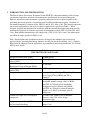
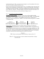
Table 1
INFLUENT FLOWS AND LOADS
Design Wastewater flow (DWF)
Monthly average value of Fats, Oil and
Grease (FOG)
Monthly average value of five day
Biochemical Oxygen Demand (BOD5)
Monthly average value of Total Suspended
Solids (TSS)
Design loading rate of fill
Design loading rate of the basal area
Volume of a single dose to absorption
component
Design wastewater flow (DWF) from one
and two-family dwellings
≤ 5000 gal/day
≤ 30 mg/L
≤ 220 mg/L
≤ 150 mg/L
≤ 1.0 gal/ft2/day if BOD5 or TSS > 30 mg/L
or ≤ 2.0 gal/ ft2/day if BOD5 and TSS ≤
30 mg/L
= soil application rate of effluent with
maximum monthly average values of BOD5
and TSS of ≤ 30 mg/L when distribution
component receives effluent with a BOD5
and TSS of ≤ 30 mg/L or when fill material
depth is ≥ 12 inches as measured at the D
dimension.
≥ 5 times void volume of the distribution
lateral (s) and ≤ 20% of the design
wastewater flow
Based on s. SPS 383.43 (3), (4), or (5), Wis.
Adm. Code
3 of 44
Table 1
INFLUENT FLOWS AND LOADS
(continued)
Design wastewater flow (DWF) from
≥ 150% of estimated daily wastewater flow in
public facilities
accordance with Table 4 of this manual or s. SPS
383.43 (6), Wis. Adm. Code
Linear loading rate for systems with in situ
≤ 4.5gal/ft/day
soils having a soil application rate of ≤ 0.3
gal/ft2/day within 12 inches of fill material
Wastewater particle size
≤ 1/8 inch
Distribution cell area per orifice
≤ 12 ft2
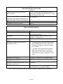
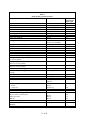
Table 2
SIZE AND ORIENTATION
Distribution cell width (A)a
Total distribution cell area (A x B)a
Orientation
Deflection of distribution cell on concave
slopes
Fill material depth at up slope edge of
distribution cell (D)a
Distribution cell depth (F)a
Depth of cover material at top center of
distribution cell area (H)a
Depth of cover material at top outer edge of
distribution cell area (G)a
Basal area
≤ 10 feet
≥ Design wastewater flow rate ÷ design loading
rate of the fill material
Longest dimension parallel to surface grade
contours on sloping sites.
≤ 10%
1. ≥ 6 inches when fill is placed on in situ soil
listed in Table 383.44-3, Wis. Adm. Code,
having fecal coliform treatment capabilities
of ≤ 36 inches, or
2. ≥ 12 inches, but not greater than 36 inches
when fill is placed on in situ soil listed in
Table 383.44-3, Wis. Adm. Code, having
fecal coliform treatment capabilities of > 36
inches.
≥ 8 inches + nominal size of distribution pipe
≥ 12 inches
≥ 6 inches
≥ Design wastewater flow rate ÷ Design loading
rate of basal area as specified in Table 1
Note a: Letter corresponds to letters referenced in figures, formulas and on worksheets.
4 of 44
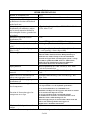
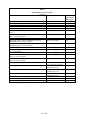
Table 3
OTHER SPECIFICATIONS
Bottom of distribution cell
Level
Slope of original grade
≤ 25% in area of basal area of the mound
Depth of in situ soil to high
≥ 6 inches
groundwater elevation and bedrock
under basal area
Vertical separation between
≥ Equal to depth required by s. SPS 383 Table 383.44distribution cell infiltrative surface
3, Wis. Adm. Code
and seasonal saturation defined by
redoximorphic features, groundwater,
or bedrock
Horizontal separation between
≥ 3 ft.
distribution cells
Fill material
Meets ASTM Specification C-33 for fine aggregate
Size for basal area (for level sites) (B Cell length x [Total mound width]
x W) a
Size for basal area (for sloping sites)
Cell length x [(# of cells x cell width) + ({# of cells –
a
(B x {A +I})
1} x cell spacing) + down slope width]
By use of pressure distribution network conforming to sizing
Effluent application
methods of either Small Scale Waste Management Project
publication 9.6, entitled “Design of Pressure Distribution
Networks for Septic Tank – Soil Absorption Systems” or Dept.
of Commerce publications SBD-10573-P or SBD-10706-P,
entitled “Pressure Distribution Component Manual for
Private Onsite Wastewater Treatment Systems”
Piping Material
Distribution cell stone aggregate
material
Fabric cover over distribution cell
when stone aggregate is used
Number of observation pipes per
distribution cell
Location of observation pipes for
level components
Location of observation pipes for
components on a slope
Meets requirements of s. SPS 384.30 (2), Wis. Adm.
Code for its intended use
Meets requirements of s. SPS 384.30 (6) (i), Wis. Adm.
Code
Geotextile fabric meeting s. SPS 384.30 (6) (g), Wis.
Adm. Code
≥2
Observation pipes will be installed in each distribution cell so as
to be representative of a cell’s hydraulic performance.
. be located such that there are a minimum of two
installed in each dispersal cell at opposite ends from one another
. be located near the dispersal cell ends
. be at least 6 inches from the end wall and sidewall
. be installed at an elevation to view the horizontal or level
infiltrative surface within the dispersal cell.
Observation pipes may be located less than 6 inches from end
walls or side walls if specified in state–approved
manufacturers’ installation instructions.
Maximum final slope of mound
≤ 3:1
surface
Note a: Letter corresponds to letters referenced in figures, formulas and on worksheets.
5 of 44
Cover material
Grading of surrounding area
Limited activities
Installation inspection
Management
II.
Table 3
OTHER SPECIFICATIONS
(continued)
Soil that will provide frost protection, prevent
erosion and excess precipitation or runoff
infiltration and allow air to enter the distribution
cell
Graded to divert surface water around mound
system
Unless otherwise specifically allowed in this
manual, vehicular traffic, excavation, and soil
compaction are prohibited in the basal area and
15 feet down slope of basal area, if there is a
restrictive horizon that negatively affects
treatment or dispersal
In accordance with ch. SPS 383, Wis. Adm.
Code
In accordance with ch. SPS 383, Wis. Adm.
Code and this manual
DEFINITIONS
Definitions not found in this section, are located in ch. SPS 381 of the Wisconsin Administrative
Code or the terms use the standard dictionary definition.
A. “Basal Area” means the effective in situ soil surface area available for infiltration of partially treated
effluent from the fill material.
B. “Deflection of distribution cell” means the ratio between the maximum distance between the down
slope edge of a concave distribution cell to the length of a perpendicular line that intersects the
furthest points of the contour line along the down slope edge of the distribution cell.
C. “Distribution cell area” means the area within the mound where the effluent is distributed into the fill
material.
D. “Fill Material” means sand that meets specifications of ASTM Standard C33 for fine aggregate and
is used along the sides of and under the distribution cell to provide treatment of effluent.
E. “Limiting Factor” means high groundwater elevation or bedrock.
F. “Mound” means an on-site wastewater treatment and dispersal component. The structure contains a
distribution cell area surrounded by, and elevated above, the original land surface by suitable fill
material. The fill material provides a measurable degree of wastewater treatment and allows effluent
dispersal into the natural environment under various soil permeability.
G. “Original Grade” means that land elevation immediately prior to the construction of the mound
system.
H. “Parallel to surface grade contours on sloping sites” means the mound is on the contour except that a
1% cross slope is allowed along the length of the mound. See Ch. SPS 383 Appendix A-383.44
ORIENTATION (6).
6 of 44
I. “Permeable Soil” means soil with textural classifications according to the U.S. Department of
Agriculture, Natural Resource Conservation Service, classification system of silt loam to gravelly
medium sand.
J.
“Slowly Permeable Soil” means soil with textural classifications according to the U.S. Department
of Agriculture, Natural Resource Conservation Service, classification system of clay loams and silty
clay loams that exhibit a moderate grade of structure; and loams, silt loams, and silts with weak
grades of structure; or soils with weak to moderate grades of platy structure.
K. “Unsaturated flow” means liquid flow through a soil media under a negative pressure potential.
Liquids containing pathogens and pollutants come in direct contact with soil/fill material microsites,
which enhances wastewater treatment by physical, biological, and chemical means.
L. “Vertical Flow” means the effluent flow path downward through soil or fill material, which involves
travel along soil surfaces, or through soil pores.
M. “Vertical Separation” means the total depth of unsaturated soil that exists between the infiltrative
surface of a distribution cell and limiting factor (as by redoximorphic features, groundwater or
bedrock.
III.
DESCRIPTION AND PRINCIPLE OF OPERATION
POWTS mound component operation is a two-stage process involving both wastewater treatment
and dispersal. Treatment is accomplished predominately by physical and biochemical processes
within the fill material and in situ soil. The physical characteristics of the influent wastewater,
influent loading rate, temperature, and the nature of the receiving fill material and in situ soil affect
these processes.
Physical entrapment, increased retention time, and conversion of pollutants in the wastewater are
important treatment objectives accomplished under unsaturated conditions. Pathogens contained in
the wastewater are eventually deactivated through filtering, retention, and adsorption by the fill
material. In addition, many pollutants are converted to other chemical forms by oxidation processes.
Dispersal is primarily affected by the depth of the unsaturated receiving soils, their hydraulic
conductivity, land slope, and the area available for dispersal.
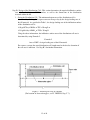
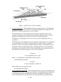
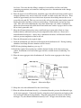
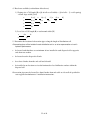
The mound consists of fill material, a distribution cell, and cover material. Effluent is dispersed into
the distribution cell where it flows through the fill material and undergoes biological, chemical and
physical treatment and then passes into the underlying soil for further treatment and dispersal to the
environment.
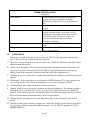
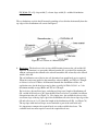
Cover material consisting of material that provides erosion protection, a barrier to excess
precipitation infiltration, and allows gas exchange. See Figure 1, for a typical mound system.
The in situ soil serves in combination with the fill, as treatment media and it also disperses the
treated effluent.
7 of 44
Figure 1 - A cross-section-of a mound system for POWTS.
IV.
SOIL AND SITE REQUIREMENTS
Every mound design is ultimately matched to the given soil and site.
The design approach presented in this manual is based on criteria that all applied wastewater is
successfully transported away from the system, that it will not affect subsequent wastewater
additions, and that the effluent is ultimately treated.
A. Minimum Soil Depth Requirements - The minimum soil factors required for successful mound
system performance are listed in the introduction and specification section of this package.
Soil evaluations must be in accordance with ch. SPS 385 of the Wis. Adm. Code. In
addition, soil application rates must be in accordance with ch. SPS 383 of the Wis. Adm.
Code.
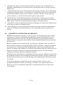
B. Other Site Considerations 1. Slopes - The slope on which a mound is to be installed may not indicate the direction of
groundwater movement. If there is documentation that the direction of groundwater
movement is different than the slope of the land, the direction of groundwater movement
must be considered during mound design.
On a crested site the fill can be situated such that the effluent can move laterally down both
slopes. A level site allows lateral flow in all directions, but may present problems as the
water table could rise higher beneath the fill in slowly permeable soils. The sloping site
allows the liquid to move in one direction away from the fill. Figure 3 shows a cross-section
of a mound and the effluent movement in a slowly permeable soil on a sloping site. Systems
that are installed on a concave slope may have a deflection that does not exceed that allowed
in Table 2.
Mound components rely on lateral effluent movement through the upper soil horizons.
Lateral movement becomes more important as soil permeability decreases.
2. Mound location - In open areas, exposure to sun and wind increases the assistance of
evaporation and transpiration in the dispersal of the wastewater.
3. Sites with trees and large boulders - Generally, sites with large trees, numerous smaller trees
or large boulders are less desirable for installing a mound system because of difficulty in
preparing the surface and the reduced infiltration area beneath the mound. Areas that are
8 of 44
occupied with rock fragments, tree roots, stumps and boulders reduce the amount of soil
available for proper treatment. If no other site is available, trees in the basal area of the
mound must be cut off at ground level. A larger fill area is necessary when any of the above
conditions are encountered, to provide sufficient infiltrative area.
4. Setback distances - The setbacks specified in ch. SPS 383, Wis. Adm. Code for soil
subsurface treatment/dispersal component apply to mound systems. The distances are
measured from the up slope and end slope edge of the distribution cell and from the down
slope toe of the mound. See also setback distances from toe of mound system to wells in s.
NR 812.08, Table A.
V.
FILL AND COVER MATERIAL
A. Fill Material - The fill material and its placement are one of the most important components of
the mound system. Quality control of the fill material is critical to system performance, each
truckload of material must meet specifications for the fill.
Determining whether a proposed fill material is suitable or not requires that a textural analysis
be performed. The standard method to be used for performing this analysis conforms to ASTM
C-136, Method for Sieve Analysis of Fine and Coarse Aggregates, and ASTM E-11,
Specifications for Wire-Cloth Sieves for Testing Purposes, Annual Book of ASTM Standards,
Volume 04.02. Information concerning these methods can also be obtained from Methods of
Soils Analysis Part 1, C. A. Black, ed., ASA, Monograph #9, American Society of Agronomy,
Inc., 1975.
B. Cover material - The cover material is a soil that will allow air exchange while promoting plant
growth. The gas exchange will increase the treatment performance of the system by providing
oxygen to the wastewater to help ensure aerobic conditions in the mound system. The plant
growth will provide frost protection in the winter season. Clays may not be used for cover
material as they will restrict oxygen transfer. Often, excavated soil from the site can be used.
Seeding or other means must be done to prevent erosion of the mound.
VI.
DESIGN
A. Location, Size and Shape - Placement, sizing and shaping of the mound and the distribution cell
within the mound must be in accordance with this manual. The means of pressurizing the
distribution network must provide equal distribution of the wastewater. A pressurized
distribution network using a method of sizing as described in either Small Scale Waste
Management Project publication 9.6, entitled “Design of Pressure Distribution Networks for
Septic Tank – Soil Absorption System” or Dept. of Commerce publications SBD-10573-P or
SBD-10706-P, entitled “Pressure Distribution Component Manual for Private Onsite Wastewater
Treatment Systems” is acceptable.
B. Component Design - Design of the mound system is based upon the design wastewater flow and
the soil characteristics. It must be sized such that it can accept the design wastewater flow
without causing surface seepage or groundwater pollution. Consequently, the basal area, which
is the in situ soil area beneath the fill, must be sufficiently large enough to absorb the effluent
9 of 44
into the underlying soil. The system must also be designed to avoid encroachment of the water
table into the required minimum unsaturated zone.
Design of the mound includes the following three steps: (A) calculating design wastewater flow,
(B) design of the distribution cell within the fill, (C) design of the entire mound. This includes
calculating total width, total length, system height, distribution lateral location and observation
pipes. Each step is discussed. A design example is provided in section XI of the manual. The
letters for the various dimensions correlate with those in Figures 2 and 3.
Step A. Design Wastewater Flow Calculations
One- and two-family dwellings. Distribution cell size for one and two-family dwelling
application is determined by calculating the design wastewater flow (DWF). To calculate DWF
use, Formulas 1, 2 or 3. Formula 1 is for combined wastewater flows, which consist of
blackwater, clearwater and graywater. Formula 2 is for only clearwater and graywater. Formula
3 is blackwater only.
Formula 1
Combined wastewater
DWF = 150 gal/day/bedroom
Formula 2
Clearwater & Graywater
DWF = 90 gal/day/bedroom
Formula 3
Blackwater
DWF = 60 gal/day/bedroom
Public Facilities. Distribution cell size for public facilities application is determined by
calculating the DWF using Formula 4. Only facilities identified in Table 4 are included in this
manual. Estimated daily wastewater flows are determined in accordance with Table 4 or s. SPS
383.43(6), Wis. Adm. Code. Many commercial facilities have high BOD5, TSS and FOG (fats,
oils and grease), which must be pretreated in order to bring their values down to an acceptable
range before entering into the mound component described in this manual.
Formula 4
DWF = Sum of each estimated wastewater flow per source per day x 1.5
Where 1.5 = Conversion factor to convert estimated wastewater flow to design
wastewater flow
10 of 44
Table 4
Source
Public Facility Wastewater Flows
Unit
Apartment or Condominium
Assembly hall (no kitchen)
Bar or cocktail lounge (no meals served)
Bar or cocktail lounge* (w/meals – all paper service)
Beauty salon
Bowling alley
Bowling alley (with bar)
Camp, day and night
Camp, day use only (no meals served)
Campground or Camping Resort
Campground sanitary dump station
Catch basin
Church (no kitchen)
Church* (with kitchen)
Dance hall
Day care facility (no meals prepared)
Day care facility* (with meal preparation)
Dining hall* (kitchen waste only without dishwasher and/or
food waste grinder)
Dining hall* (toilet and kitchen waste without dishwasher
and/or food waste grinder)
Dining hall* (toilet and kitchen waste with dishwasher
and/or food waste grinder)
Drive-in restaurant* (all paper service with inside seating)
Drive-in restaurant* (all paper service without inside
seating)
Drive-in theater
Employees (total all shifts)
Floor drain (not discharging to catch basin)
Gas station / convenience store
Gas station (with service bay)
Patron
Service bay
Hospital*
Hotel, motel or tourist rooming house
Medical office building
Doctors, nurses, medical staff
Office personnel
Patients
Migrant labor camp (central bathhouse)
Mobile Home (Manufactured home) (served by its own
POWTS)
Mobile home park
* = May be high strength waste
Estimated
Wastewater
Flow (gpd)
100
1.3
4
8
90
80
150
25
10
30
Bedroom
Person (10 sq. ft./person)
Patron (10 sq. ft./patron)
Patron (10 sq. ft./patron)
Station
Bowling lane
Bowling lane
Person
Person
Space, with sewer connection
and/or service building
Camping unit or RV served
Basin
Person
Person
Person (10 sq. ft./person)
Child
Child
Meal served
25
65
2
5
2
12
16
2
Meal served
5
Meal served
7
Patron seating space
Vehicle space
10
10
Vehicle space
Employee
Drain
Patron (minimum 500
patrons)
3
13
25
3
Patron
Service bay
Bed space
Room
3
50
135
65
Person
Person
Person
Employee
Bedroom
50
13
6.5
20
100
Mobile home site
200
11 of 44
Table 4
Source
Public Facility Wastewater Flows
(continued)
Unit
Nursing, Rest Home, Community Based Residential Facility
Outdoor sport facilities (toilet waste only)
Parks (toilets waste only)
Parks (toilets and showers)
Public shower facility
Restaurant*, 24-hr. (dishwasher and/or food waste grinder
only)
Restaurant*, 24-hr. (kitchen waste only without dishwasher
and/or food waste grinder)
Restaurant, 24-hr. (toilet waste)
Restaurant*, 24-hr. (toilet and kitchen waste without
dishwasher and/or food waste grinder)
Restaurant*, 24-hr. (toilet and kitchen waste with
dishwasher and/or food waste grinder)
Restaurant* (dishwasher and/or food waste grinder only)
Restaurant* (kitchen waste only without dishwasher and/or
food waste grinder)
Restaurant (toilet waste)
Restaurant* (toilet and kitchen waste without dishwasher
and/or food waste grinder)
Restaurant* (toilet and kitchen waste with dishwasher
and/or food waste grinder)
Retail store
School* (with meals and showers)
School* (with meals or showers)
School (without meals or showers)
Self-service laundry (toilet waste only)
Self-service laundry (with only residential clothes washers)
Swimming pool bathhouse
* = May be high strength waste
Bed space
Patron
Patron (75 patrons/acre)
Patron (75 patrons/acre)
Shower taken
Patron seating space
Estimated
Wastewater
Flow (gpd)
65
3.5
3.5
6.5
10
4
Patron seating space
12
Patron seating space
Patron seating space
28
40
Patron seating space
44
Patron seating space
Patron seating space
2
6
Patron seating space
Patron seating space
14
20
Patron seating space
22
Patron (70% of total retail
area ÷ 30 sq. ft. per patron)
Classroom (25
students/classroom)
Classroom (25
students/classroom)
Classroom (25
students/classroom)
Clothes washer
Clothes washer
Patron
1
12 of 44
500
400
300
33
200
6.5
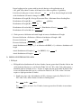
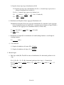
Step B. Design of the Distribution Cell - This section determines the required infiltrative surface
area of the distribution cell/fill interface, as well as the dimensions of the distribution
network within the fill.
1. Sizing the Distribution Cell - The minimum bottom area of the distribution cell is
determined by dividing the design wastewater flow per day by the design loading rate of
the fill material. As specified in Table 1, the design loading rate of the infiltration surface
of the distribution cell is:
2
≤1.0 gal/ft /day if BOD5 or TSS > 30 mg/L or
≤ 2.0 gal/ft2/day if BOD5 or TSS ≤ 30 mg/L
Using the above information, the infiltrative surface area of the distribution cell area is
determined by using Formula 5.
Formula 5
Area = DWF ÷ design loading rate of the fill material.
For concave systems the actual distribution cell length must be checked to determine if
the cell area is sufficient. See Step B 3 for further information.
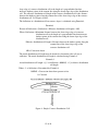
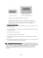
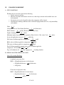
Figure 2 - Detailed plan view of a mound.
(For location of observation pipes, see IV. DESIGN, Step C 7.)
13 of 44
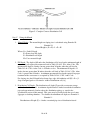
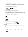
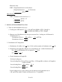
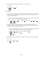
Figure 3 - Detailed cross-section of a mound.
2. System Configuration - The distribution cell must be longer than it is wide. Maximum
width of the distribution cell is 10 feet. The maximum length of the distribution cell is
dependent on setback requirements and soil evaluation.
The distribution cell is aligned with its longest dimension parallel to surface grade
contours on sloping sites as required by the specifications of this package so as not to
concentrate the effluent into a small area as it moves laterally down slope.
The bottom of the distribution cell is level so one area of the distribution cell is not
overloaded.
The dimensions for the distribution cell are calculated using Formulas 6 or 7. Formula 6
is used when the in situ soil has a soil application rate of greater then 0.3 gal/ft2/day.
Formula 7 must be used to check for linear loading rate for the system when the in situ
soil within 12 inches of the fill material has a soil application rate of ≤ 0.3 gal/ft2/day.
When the in situ soil within 12 inches of the fill material has a soil application rate of ≤
0.3 gal/ft2/day the linear loading rate my not exceed 4.5 gal/ft/day.
Formula 6
Area of distribution cell = A x B.
Where: A = Distribution cell width (Max. allowed is 10 ft.)
B = Distribution cell length
Formula 7
Linear Loading Rate = DWF ÷ B
Where: DWF = Design wastewater flow
B = Distribution cell length
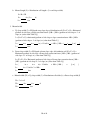
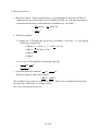
3. Concave Mound Configuration – The maximum deflection of a concave distribution cell
of a mound system is 10%. The percent of deflection of a distribution cell is determined
by dividing the amount of deflection by the effective distribution cell length of the
concave distribution cell. The deflection is the maximum distance between the down
14 of 44
slope edge of a concave distribution cell to the length of a perpendicular line that
intersects furthest points of the contour line along the down slope edge of the distribution
cell. The effective distribution cell length of the concave distribution cell is the distance
between the furthest points along the contour line of the down slope edge of the concave
distribution cell. See Figures 4 and 5.
The deflection of a distribution cell on concave slopes is calculated using Formula 8.
Formula 8
Percent of Deflection = (Deflection ÷ Effective distribution cell length) x 100
Where: Deflection = Maximum distance between the down slope edge of a concave
distribution cell to the length of a perpendicular line that intersects
furthest points of the contour line along the down slope edge of the
distribution cell
Effective distribution cell length = Distance between the furthest points along the
contour line of the down slope edge of the
concave distribution cell
100 = Conversion factor
The actual distribution cell length must be checked to determine if the cell area is
sufficient. The actual distribution cell length is calculated using Formula 9.
Formula 9
Actual distribution cell length = [(% of deflection x 0.00265) + 1] x effective distribution
cell length
Where: % of deflection = Determined by Formula 8
0.00265 = Conversion factor from percent to feet
1 = Constant
Figure 4– Simple Concave Distribution Cell
15 of 44
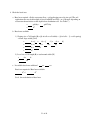
Figure 5– Complex Concave Distribution Cell
Step C.
Sizing the Mound
1. Mound Height - The mound height on sloping sites is calculated using Formula 10.
Formula 10
Mound Height = (D + E) ÷2 + F + H
Where: D = Sand fill depth
E = Down slope fill depth
F = Distribution cell depth
H = Cover material depth
2. Fill Depth - The depth of fill under the distribution cell is based on the minimum depth of
unsaturated soil required for treatment listed in Table 383.44-3, Wis. Adm. Code. The
minimum fill depth is 6 inches, but not greater than 36 inches when the soil listed in
Table 383.44-3, Wis. Adm. Code, is 36 inches or less. The minimum fill depth is 12
inches, but not greater than 36 inches when the soil listed in Table 383.44-3, Wis. Adm.
Code, is greater than 36 inches. A minimum unsaturated flow depth required for proper
treatment of the wastewater is as required by Table 383.44-3, Wis. Adm. Code.
For sloping sites the fill depth below down slope edge of distribution cell (E) ≥ D + [%
slope of original grade as a decimal x width of distribution cell (A)]
3. Distribution Cell Depth - The distribution cell depth (F) provides wastewater storage
within the distribution cell. A minimum depth includes 6 inches beneath the distribution
pipe and approximately 2 inches above the distribution piping, as stated in the
specification section of this manual. This space may be provided with the use of stone
aggregate or leaching chambers. To calculate the minimum cell depth, use Formula 11.
Formula 11
Distribution cell depth (F) = 8 inches + nominal pipe size of distribution lateral
16 of 44
4. Cover Material - The cover material (G & H) provides frost protection and a suitable
growth medium for vegetation. For design purposes, use a depth of 12 inches above the
center of the distribution cell (H) and 6 inches above the outer edge of the distribution
cell (G).
Cover material depth at distribution cell center (H) ≥ 12 inches
Cover material depth at distribution cell edges (G) ≥ 6 inches
5. Fill Length and Width - The length and width of the fill are dependent upon the length
and width of the distribution cell, fill depth and side slopes of the fill. Side slopes may
not be steeper than 3:1 over the basal area, (i.e. 3 feet of run to every 1 foot of rise). Soil
having textures other than those specified for the fill media may be used to make the
slopes gentler than the required 3:1 slopes, once the 3:1 slope exists with the fill material.
The distribution cell length is generally perpendicular to the direction of slope so the
effluent is spread out along the contour.
The fill length consists of the end slopes (K) and the distribution cell length (B). The fill
width consists of the up slope width (J), the distribution cell width (A), and the down
slope width (I). On sloping sites the up slope width (J) is less while the down slope
width (I) is greater than on a level site to maintain the 3:1 side slope (see Fig. 2). To
calculate the up slope and down slope widths when a 3:1 side slope is maintained,
multiply the calculated width by the correction factor found by using the following
equations or the correction factor listed in Table 5.
Up slope correction factor = 100 ÷ [100 + (3 x % of slope)]
Down slope correction factor = 100 ÷ [100 - (3 x % of slope)]
17 of 44
Table 5
Down slope and up slope width correction factors
Slope %
Down slope
Up Slope correction
correction factor
factor
0
1
2
3
4
5
6
7
8
9
10
11
12
13
14
15
16
17
18
19
20
21
22
23
24
25
1.00
1.03
1.06
1.10
1.14
1.18
1.22
1.27
1.32
1.37
1.43
1.49
1.56
1.64
1.72
1.82
1.92
2.04
2.17
2.33
2.50
2.70
2.94
3.23
3.57
4.00
1.00
0.97
0.94
0.915
0.89
0.875
0.85
0.83
0.81
0.79
0.77
0.75
0.735
0.72
0.705
0.69
0.675
0.66
0.65
0.64
0.625
0.61
0.60
0.59
0.58
0.57
The most critical dimensions of the fill are: fill depths (D) & (E), distribution cell length
(B), distribution cell width (A), and the down slope width (I).
End slope width (K) = Total fill at center of distribution cell {[(D + E) ÷2]+ F + H} x
horizontal gradient of selected side slope (3 if 3:1 side-slope)
Fill Length (L) = Distribution cell length (B) + 2 x end slope width (K)
Up slope width (J) = Fill depth at up slope edge of distribution cell (D + F + G) x
horizontal gradient of side slope (3 if 3:1) x slope correction factor {100 ÷ [100 + (3 x %
of slope)] if 3:1}
Down slope width (I) = Fill depth at down slope edge of distribution cell (E + F + G) x
horizontal gradient of side slope (3 if 3:1) x slope correction factor {100 ÷ [100 - (3 x %
of slope)] if 3:1}
18 of 44
Fill Width (W) = Up slope width (J) + down slope width (I) + width of distribution
cell (A)
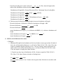
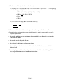
These calculations result in the fill material extending at least 6 inches horizontally from the
top edges of the distribution cell as noted in Figure 6.
Figure 6 Cross-section of a Mound System
6. Basal Area - The basal area is the in situ soil/fill interface between the soil and the fill
material. Its function is to accept the effluent from the fill, assist the fill in treating the
effluent, and transfer the effluent to the subsoil beneath the fill or laterally to the subsoil
outside of the fill.
The soil infiltration rate of the in situ soil determines how much basal area is required.
When the wastewater applied to the mound has values for BOD5 and TSS of ≤ 30 mg/L
or if there is at least 12 inches of fill material beneath the distribution cell the soil
application rates for the basal area may be those specified in Table 383.44-1 or -2 for
maximum monthly average BOD5 and TSS of ≤ 30 mg/L.
For level sites, the total basal area, excluding end slope area [length of distribution cell
(B) x width of fill and cover (W)] beneath the fill and soil cover is available for effluent
absorption into the soil (see Figure 7a). For sloping sites, the available basal area is the
area down slope of the up slope edge of the distribution cell to the down slope edge of the
fill and soil cover or (A + I) times the length of the distribution cell (B) (see Figure 7b).
The up slope width and end slopes are not included as part of the total basal area.
It is important to compare the required basal area to the available basal area. The
available basal area must equal or exceed the required basal area.
19 of 44
Figure 7a Level site
Figure 7b One direction slope
Basal area required = DWF ÷ Infiltration rate of in situ soil
Basal area available = B x W on a level site or = B x (A+I) on a sloping site.
If sufficient area is not available for the given design and site conditions, corrective
action is required to increase (J) and (I) on level sites or (I) on sloping sites.
7. Location of the observation pipes.
Observation pipes will be installed in each distribution cell so as to be representative of a cell’s
hydraulic performance.
•
be located such that there are a minimum of two installed in each dispersal cell at opposite
ends from one another
•
be located near the dispersal cell ends
•
be at least 6 inches from the end wall and sidewall
•
be installed at an elevation to view the horizontal or level infiltrative surface within the
dispersal cell
Observation pipes may be located less than 6 inches from end walls or side walls if specified in
state–approved manufacturers’ installation instructions.
Step D. Distribution Network and Dosing System A pressurized distribution network based on a
method of sizing as described in either Small Scale Waste Management Project publication 9.6,
entitled “Design of Pressure Distribution Networks for Septic Tank – Soil Absorption Systems”
or Dept. of Commerce publications SBD-10573-P or SBD-10706-P, entitled “Pressure
Distribution Component Manual for Private Onsite Wastewater Treatment Systems” is
acceptable.
20 of 44
VII.
SITE PREPARATION AND CONSTRUCTION
Procedures used in the construction of a mound system are just as critical as the design of the
system. A good design with poor construction results in system failure. It is emphasized that the
soil only be tilled when it is not frozen and the moisture content is low to avoid compaction and
puddling. The construction plan to be followed includes:
A. Equipment - Proper equipment is essential. Track type tractors or other equipment that will not
compact the mound area or the down slope area are required.
B. Sanitary Permit - Prior to the construction of the system, a sanitary permit, obtained for the
installation must be posted in a clearly visible location on the site. Arrangements for
inspection(s) must also be made with the department or governmental unit issuing the sanitary
permit.
C. Construction Procedures
1. Check the moisture content of the soil to a depth of 8 inches. Smearing and compacting of
wet soil will result in reducing the infiltration capacity of the soil. Proper soil moisture
content can be determined by rolling a soil sample between the hands. If it rolls into a 1/4inch wire, the site is too wet to prepare. If it crumbles, site preparation can proceed. If the
site is too wet to prepare, do not proceed until it dries.
2. Lay out the fill area on the site so that the distribution cell runs perpendicular to the direction
of the slope.
3. Establish the original grade elevation (surface contour) along the up slope edge of the
distribution cell. This elevation is used throughout the mound construction as a reference to
determine the bottom of the distribution cell, lateral elevations, etc., and is referenced to the
permanent bench mark for the project. A maximum of 4 inches of sand fill may be tilled into
the surface.
4. Determine where the force main from the dosing chamber will connect to the distribution
system in the distribution cell. Place the pipe either before tilling or after placement of the
fill. If the force main is to be installed in the down slope area, the trench for the force main
may not be wider then 12 inches.
5. Cut trees flush to the ground and leave stumps, remove surface boulders that can be easily
rolled off, remove vegetation over 6 inches long by mowing and removing cut vegetation.
Prepare the site by breaking up, perpendicular to the slope, the top 7-8 inches so as to
eliminate any surface mat that could impede the vertical flow of liquid into the in situ soil.
When using a moldboard plow, it should have as many bottoms as possible to reduce the
number of passes over the area to be tilled and minimize compaction of the subsoil. Tilling
with a moldboard plow is done along contours. Chisel type plowing is highly recommended
especially in fine textured soils. Rototilling or other means that pulverize the soil is not
acceptable. The important point is that a rough, unsmeared surface be left. The sand fill will
intermingle between the clods of soil, which improves the infiltration rate into the natural
soil.
Immediate application of at least 6 inches of fill material is required after tilling. All
vehicular traffic is prohibited on the tilled area. For sites where the effluent may move
laterally, vehicle traffic is also prohibited for 15 ft. down slope and 10 ft. on both sides of
21 of 44
level sites. If it rains after the tilling is completed, wait until the soil dries out before
continuing construction, and contact the local inspector for a determination on the damage
done by rainfall.
6. Place the approved sand fill material, around the edge of the tilled area being careful to leave
adequate perimeter area, not covered by the sand fill, on which to place the soil cover. There
should be approximately two feet of basal area adjacent to the mound perimeter that is not
covered by the sand fill. This area serves to tie the soil cover into the natural surface material
that has been tilled and helps seal the toe from leakage. Work from the end and up slope
sides. This will avoid compacting the soils on the down slope side, which, if compacted,
affects lateral movement away from the fill and could cause surface seepage at the toe of the
fill on slowly permeable soils.
7. Move the fill material into place using a small track type tractor with a blade or a large
backhoe that has sufficient reach to prevent compaction of the tilled area. Do not use a
tractor/backhoe having tires. Always keep a minimum of 6 inches of fill material beneath
tracks to prevent compaction of the in situ soil.
8. Place the fill material to the required depth.
9. Form the distribution cell. Hand level the bottom of the distribution cell. If using leaching
chambers, hand tamp fill where chambers will be located.
NOTE: If using leaching chambers go to step 15.
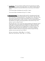
10. Install the required observation pipes with the bottom 6 inches of the observation pipe
slotted. Installations of all observation pipes include a suitable means of anchoring. See
Figure 8.
11. Place the stone aggregate in the distribution cell. Level the stone aggregate to the design
depth.
Figure 8 – Observation Pipes
12. Shape the sides with additional fill to the desired slopes.
13. Place the effluent distribution lateral(s), as determined from the pressure distribution design,
on the stone aggregate. Connect the lateral(s) using the needed connections and piping to the
force main pipe from the dosing chamber. Slope the piping from the lateral(s) to the force
main pipe. Lay the effluent distribution lateral(s) level. All pipes must drain after dosing.
22 of 44
14. Place stone aggregate over the distribution network and the entire distribution cell until the
elevation of the stone aggregate is at least 2 inches above the top of the distribution network.
NOTE: If using stone aggregate go to step 17.
15. Install the leaching chambers and pressure distribution piping as instructed by the leaching
chamber manufacturer’s instructions, pressure distribution design and applicable sections of
ch. SPS 382, 83 and 84, Wis. Adm. Code.
16. Install an observation pipe in each row of leaching chambers.
17. If stone aggregate is used, place geotextile fabric conforming to requirements of ch. SPS 384,
Wis. Adm. Code, over the stone aggregate.
18. Place cover material on the top of the geotextile fabric and extend the soil cover to the
boundaries of the overall component.
19. Complete final grading to divert surface water drainage away from mound. Sod or seed and
mulch the entire mound component.
VIII. OPERATION, MAINTENANCE AND PERFORMANCE MONITORING
A. The component owner is responsible for the operation and maintenance of the component. The
county, department or POWTS service contractor may make periodic inspections of the
components, checking for surface discharge, treated effluent levels, etc.
The owner or owner's agent is required to submit necessary maintenance reports to the
appropriate jurisdiction and/or the department.
B. Design approval and site inspections before, during, and after the construction are accomplished
by the county or other appropriate jurisdictions in accordance to ch. SPS 383 of the Wis. Adm.
Code.
C. Routine and preventative maintenance aspects:
1. Treatment and distribution tanks are to be inspected routinely and maintained when necessary
in accordance with their approvals.
2. Inspections of the mound component performance are required at least once every three
years. These inspections include checking the liquid levels in the observation pipes and
examination for any seepage around the mound component.
3. Winter traffic on the mound is not advised to avoid frost penetration and to minimize
compaction.
4. A good water conservation plan within the house or establishment will help assure that the
mound component will not be overloaded.
23 of 44
D. User's Manual: A user's manual is to accompany the component. The manual is to contain the
following as a minimum:
1. Diagrams of all components and their location. This should include the location of the
reserve area, if one is provided.
2. Names and phone numbers of local health authority, component manufacturer or POWTS
service contractor to be contacted in the event of component failure or malfunction.
3. Information on periodic maintenance of the component, including electrical/mechanical
components.
4. Information on limited activities on reserve area if provided.
E. Performance monitoring must be performed on mound systems installed under this manual.
1. The frequency of monitoring must be:
a. At least once every three years following installation and,
b. At time of problem, complaint, or failure.
2. The minimum criteria addressed in performance monitoring of mound systems are:
a. Type of use.
b. Age of system.
c. Nuisance factors, such as odors or user complaints.
d. Mechanical malfunction within the system including problems with valves or other
mechanical or plumbing components.
e. Material fatigue or failure, including durability or corrosion as related to construction or
structural design.
f. Neglect or improper use, such as exceeding the design rate, poor maintenance of
vegetative cover, inappropriate cover over the mound, or inappropriate activity over the
mound.
g. Installation problems such as compaction or displacement of soil, improper orientation or
location.
h. Pretreatment component maintenance, including dosing frequency, structural integrity,
groundwater intrusion or improper sizing.
i. Dose chamber maintenance, including improper maintenance, infiltration, structural
problems, or improper sizing.
j. Distribution piping network, including improper maintenance or improper sizing.
k. Ponding in distribution cell, prior to the pump cycle, is evidence of development of a
clogging mat or reduced infiltration rates.
l. Siphon or pump malfunction including dosing volume problems, pressurization
problems, breakdown, burnout, or cycling problems.
m. Overflow/seepage problems, as shown by evident or confirmed sewage effluent,
including backup if due to clogging.
24 of 44
4. Reports are to be submitted in accordance with ch. SPS 383, Wis. Adm. Code..
IX.
REFERENCES
“Wisconsin Mound Soil Absorption System: Siting, Design and Construction.” Converse, J.C., and E. J.
Tyler. Publication 15.22, Small Scale Waste Management Project., 1 Agriculture Hall, University of
Wisconsin, Madison, WI.
25 of 44
X.
MOUND WORKSHEET
A. SITE CONDITIONS
Evaluate the site and soils report for the following:
• Surface water movement.
• Measure elevations and distances on the site so that slope, contours and available areas can
be determined.
• Description of several soil profiles where the component will be located.
• Determine the limiting conditions such as bedrock, high groundwater level, soil application
rates, and setbacks.
Slope -
%
Occupancy – One or Two-Family Dwelling Public Facility -
(# of bedrooms)
gal/day (Estimated wastewater flow)
Depth to limiting factor -
inches
Minimum depth of unsaturated soil required by Table 383.44-3, Wis. Adm. Code gal/ft2/day
Soil application rate of in situ soil used -
mg/L
FOG value of effluent applied to component BOD5 value of effluent applied to component -
mg/L
mg/L
TSS value of effluent applied to component -
Fecal Coliform monthly geometric mean value of effluent applied to
component > 104 cfu/100ml Yes
No
Type of distribution cell -
Stone aggregate or
Leaching chamber
B. DESIGN WASTEWATER FLOW (DWF)
One or Two-family Dwelling.
Combined wastewater flow:
DWF = 150 gal/day/bedroom x # of bedrooms
= 150 gal/day/bedroom x
=
# of bedrooms
gal/day
Clearwater and graywater only:
DWF = 90 gal/day/bedroom x # of bedrooms
= 90 gal/day/bedroom x
=
# of bedrooms
gal/day
26 of 44
inches
Blackwater only:
DWF = 60 gal/day/bedroom x # of bedrooms
= 60 gal/day/bedroom x
=
# of bedrooms
gal/day
Public Facilities.
DWF = Estimated wastewater flow x 1.5
=
gal/day x 1.5
=
gal/day
C. DESIGN OF THE DISTRIBUTION CELL
1. Total size of the Distribution Cell(s) area
a. Loading rate of fill material =
≤ 1.0 gal/ft2/day if BOD5 or TSS > 30 mg/L or
≤ 2.0 gal/ft2/day if BOD5 or TSS ≤ 30 mg/L
b. Bottom area of total distribution cell area = Design wastewater flow ÷ loading rate of fill as
determined in C.1.a.
gal/ft2/day
gal/day ÷
Distribution cell area =
ft
Distribution cell area =
2
2. Distribution Cell Configuration
a. Distribution cell width(s) (A) =
feet ( ≤ 10 ft.) and number of distribution cells =
cells
b. Distribution cell length (B) = Bottom area of distribution cell ÷ width of distribution cell
2
B=
ft (Distribution cell area required) ÷
B=
ft
ft(A)
c. Check Distribution Cell Length (B)
For linear loading rate:
Linear Loading Rate ≤ Design Wastewater Flow ÷ Cell length (B) or effective cell length for a
concave mound)
Linear Loading Rate ≤
gal/day ÷
Linear Loading Rate ≤
gal/ft/day
27 of 44
feet
Linear loading rate for systems with in situ soils having a soil application rate of
2
≤ 0.3 gal/ft /day within 12 inches of fill must be less than or equal to 4.5 gal/ft/day.
Is the linear loading rate ≤ what is allowed?
yes
of the distribution cell must be changed so it does.
no If no, then the length and width
Distribution cell length (B) = Design Wastewater Flow ÷ Maximum Linear Loading Rate
Distribution cell length (B) =
gal/day ÷
Distribution cell length (B) =
gal/ft/day
ft
2
ft (Distribution cell area) ÷
Distribution cell total width (A) =
Distribution cell total width (A) =
ft(B)
ft
d. Check percent of deflection and actual length of concave distribution cell length
Percent of deflection = Deflection ÷ Effective distribution cell length x 100
Percent of deflection =
ft ÷
ft x 100
Percent of deflection =
% (≤ 10%)
Actual distribution cell length = [(% of deflection x 0.00265) + 1] x effective distribution cell
length
Actual distribution cell length = [(
Actual distribution cell length =
% x 0.00265) +1] x
ft
ft
D. DESIGN OF ENTIRE MOUND AREA
1. Fill Depth
a. Fill depth below distribution cell At least 6 inches, but not greater than 36 inches if the in situ
soil beneath the tilled area is a soil listed in Table 383.44-3, Wis. Adm. Code, that requires a
minimum depth of 36 inches or less. At least 12 inches, but not greater than 36 inches if the
in situ soil beneath the tilled area is a soil listed in Table 383.44-3, Wis. Adm. Code, that
requires a depth greater than 36 inches.
1) Depth at up slope edge of distribution cell (D) = distance required by Table 383.44-3,
Wis. Adm. Code, minus distance in inches to limiting factor
D=
inches -
inches
D=
inches (at least ≥ 6 or 12 inches, but not greater then 36 inches in accordance
with Table 2)
28 of 44
2) Depth at down slope edge of distribution cell (E)
E = Depth at up slope edge of distribution cell (D) + (% natural slope expressed as a
decimal x distribution cell width (A))
E = D + (% natural slope expressed as decimal x A)
E=
inches + (
E=
x
feet x 12 inches/ft)
inches
b. Distribution cell Depth for Stone Aggregate Distribution cell.
Distribution cell depth (F) for stone aggregate distribution cell = amount of stone aggregate
below distribution laterals (6 inches min.) + nominal pipe size of largest lateral + amount
of stone aggregate over distribution laterals (2 inches min.).
F=
(≥6) inches +
F=
inches +
(≥2) inches
inches
c. Distribution cell depth (F) for distribution cell with leaching chambers = total height of
leaching chamber.
F=
inches
d. Cover material
1) Depth at center of distribution cell area (H) ≥ 12 inches
2) Depth at outer edges of distribution cell area (G) ≥ 6 inches
2. Mound length
a. End slope width (K)= Total fill at center of distribution cell x horizontal gradient of side
slope
K = {([(D + E) ÷ 2] + F + H) x horizontal gradient of side slope} ÷ 12 inches/foot
K = {([(
inches +
inches/ft
K=
inches) ÷ 2] +
ft
29 of 44
inches +
inches) x
} ÷ 12
b. Mound length (L) = Distribution cell length + (2 x end slope width)
L = B + 2K
L=
ft + (2 x
L=
feet
ft)
3. Mound width
a. Up slope width (J) = Fill depth at up slope edge of distribution cell (D + F + G) x Horizontal
gradient of side slope x Slope correction factor {100 ÷ [100 + (gradient of side slope x % of
slope) or (value from Table 5)]}
J = (D + F + G) x horizontal gradient of side slope x slope correction factor 100 ÷ [100 +
(gradient of side slope x % of slope) or (value from Table 5)]
J=(
in +
J=
in +
in) ÷ 12 in/ft x
x 100 ÷ [ 100 + (
x
)] or [
]
feet
b. Down slope width (I) = Fill depth at down slope edge of distribution cell (E + F + G) x
Horizontal gradient of side slope x Down slope correction factor {100 ÷ [100 - (gradient of
side slope x % of slope) or ( value from Table 5)]}
I = (E + F + G) x Horizontal gradient of side slope x Down slope correction factor {100 ÷
[100 - (gradient of side slope x % of slope) or (value from Table 5)]}
I=(
I=
in +
in +
in) ÷ 12 in/ft x
x 100 ÷ [ 100 - (
x
)] or [
]
in ÷ 12 in/ft x 3 x 100 ÷
I=
feet
c. Mound width (W) = Up slope width (J) + Distribution cell width (A) + Down slope width (I)
W=J+A+I
W=
W=
ft +
ft +
ft
feet
30 of 44
4. Check the basal area
a. Basal area required = Daily wastewater flow ÷ soil application rate of in situ soil (The soil
application rate may be that which is listed for BOD5 and TSS > or ≤ 30 mg/L depending on
wastewater characteristics or fill depth below distribution cell. See Table 1.)
=
gal/day ÷
=
ft2
gal/ft2/day
b. Basal area available
1) Sloping site = Cell length (B) x [(# of cells x cell width) + ({# of cells – 1} x cell spacing)
+ down slope width] (A+I)
=
ft x [(
=
ft x (
=
ft x
=
2
ft
x
ft) + ({
ft +
-1} x
ft +
ft
2) Level site = Cell length (B) x total mound width (W)
=
ft x
ft
ft
=
2
c. Is available basal area sufficient?
yes
Basal area required ≤ Basal area available
ft2 ≤
ft2
See d. for recalculation of basal area
31 of 44
no
ft) +
ft)
ft]
d. Basal area available (recalculation of basal area)
1) Sloping site = Cell length (B) x [(# of cells x cell width) + ({# of cells – 1} x cell spacing)
+ down slope width] (A+I)
=
ft x [(
=
ft x (
=
ft x
=
2
ft
x
ft) + ({
ft +
-1} x
ft +
ft) +
ft]
ft)
ft
2) Level site = Cell length (B) x total mound width (W)
=
=
ft x
ft
ft
2
5. Determine the location of observation pipes along the length of distribution cell.
Observation pipes will be installed in each distribution cell so as to be representative of a cell’s
hydraulic performance.
•
be located such that there are a minimum of two installed in each dispersal cell at opposite
ends from one another
•
be located near the dispersal cell ends
•
be at least 6 inches from the end wall and sidewall
•
be installed at an elevation to view the horizontal or level infiltrative surface within the
dispersal cell
Observation pipes may be located less than 6 inches from end walls or side walls if specified in
state–approved manufacturers’ installation instructions.
32 of 44
XI.
EXAMPLE WORKSHEET
A. SITE CONDITIONS
Evaluate the site and soils report for the following:
• Surface water movement.
• Measure elevations and distances on the site so that slope, contours and available areas can
be determined.
• Description of several soil profiles where the component will be located.
• Determine the limiting conditions such as bedrock, high groundwater level, soil permeability,
and setbacks.
Slope - 6
%
Occupancy – One or Two-Family Dwelling Public Facility -
0
3
(# of bedrooms)
gal/day (Estimated wastewater flow)
Depth to limiting factor - 25
inches
Minimum depth of unsaturated soil required by Table 383.44-3, Wis. Adm. Code - 36
In situ soil application rate used - 0.3
gal/ft2/day
mg/L
FOG value of effluent applied to component - < 30
BOD5 value of effluent applied to component - 180 mg/L
TSS value of effluent applied to component - 50 mg/L
Fecal Coliform monthly geometric mean value of effluent applied to
component > 104 cfu/100ml X Yes
No
Type of distribution cell - X Stone aggregate or
Leaching chamber
B. DESIGN WASTEWATER FLOW (DWF)
One or Two-family Dwelling.
Combined wastewater flow:
DWF = 150 gal/day/bedroom x # of bedrooms
= 150 gal/day/bedroom x
3 # of bedrooms
= 450 gal/day
Clearwater and graywater only:
DWF = 90 gal/day/bedroom x # of bedrooms
= 90 gal/day/bedroom x
=
# of bedrooms
gal/day
33 of 44
inches
Blackwater only:
DWF = 60 gal/day/bedroom x # of bedrooms
= 60 gal/day/bedroom x
=
# of bedrooms
gal/day
Public Facilities.
DWF = Estimated wastewater flow x 1.5
=
gal/day x 1.5
=
gal/day
C. DESIGN OF THE DISTRIBUTION CELL
1. Total size the Distribution cell(s) area
a. Loading rate of fill material = X ≤ 1.0 gal/ft2/day if BOD5 or TSS > 30 mg/L or
≤ 2.0 gal/ft2/day if BOD5 or TSS ≤ 30 mg/L
b. Bottom area of distribution cell = Design wastewater flow ÷ loading rate of fill material a
determined in C.1.a.
Distribution cell area = 450 gal/day ÷ 1.0 gal/ft2/day
Distribution cell area = 450 ft2
2. Distribution cell Configuration
a. Distribution cell width(s) (A) = 7 feet (≤ 10 ft.) and the number of distribution cells = 1 cells
b. Distribution cell length (B) = Bottom area of distribution cell ÷ width of distribution cell
B = 450 ft2 (Distribution cell area required) ÷ 7 ft(A)
B = 64.29 or 65 ft
c. Check distribution cell length (B)
For linear loading rate:
Linear Loading Rate ≤ Design Wastewater Flow ÷ Cell length (B) or effective cell length for
a concave mound)
Linear Loading Rate ≤
450 gal/day ÷ 65 ft
Linear Loading Rate ≤ 6.92 gal/ft
Linear loading rate for systems with in situ soils having an soil application rate of
≤ 0.3 gal./ft2/day within 12 inches of fill must be less ≤ 4.5 gal/ft/day.
34 of 44
Is the linear loading rate ≤ what is allowed?
yes x no If no, then the length and/or
width of the distribution cell must be changed so it does.
Distribution cell length (B) = Design Wastewater Flow ÷ Maximum Linear Loading Rate
Distribution cell length (B) = 450 gal/day ÷ 4.5 gal/ft/day
Distribution cell length (B) = 100 ft
Distribution cell width (A) = 450 ft2 (Distribution cell area) ÷ 100 ft(B)
Distribution cell width (A) = 4.5 ft2
d. Check percent of deflection and actual length of concave distribution cell length
Percent of deflection = Deflection ÷ Effective distribution cell length x 100
Percent of deflection =
ft ÷
ft x 100
Percent of deflection =
% (≤ 10%)
Actual distribution cell length = [(% of deflection x 0.00265) + 1] x effective distribution cell
length
Actual distribution cell length = [(
Actual distribution cell length =
% x 0.00265) +1] x
ft
ft
D. DESIGN OF ENTIRE MOUND AREA
1. Fill Depth
a. Minimum fill depth below distribution cell At least 6 inches, but not greater than 36 inches if
the in situ soil beneath the tilled area is a soil listed in Table 383.44-3, Wis. Adm. Code, that
requires a minimum depth of 36 inches or less. At least 12 inches, but not greater than 36
inches if the in situ soil beneath the tilled area is a soil listed in Table 383.44-3, Wis. Adm.
Code, that requires a depth greater than 36 inches.
1) Depth at up slope edge of distribution cell (D) = distance required by Table 383.44-3,
Wis. Adm. Code, minus distance in inches to limiting factor
D = 36 inches - 25 inches
D = 11 inches (at least ≥ 6 or 12 inches, but not greater than 36 inches in accordance with
Table 2)
35 of 44
2) Depth at down slope edge of distribution cell (E)
E = Depth at up slope edge of distribution cell (D) + (% natural slope expressed as a
decimal x distribution cell width (A))
E = D + (% natural slope expressed as decimal x A)
E=
11 inches + ( 0.06 x
4.5
feet x 12 inches/ft)
E = 14.24 or 14.25 inches
b. Distribution cell Depth for Stone Aggregate Distribution cell.
Distribution cell depth (F) for stone aggregate distribution cell = amount of stone aggregate
below distribution laterals (6 inches min.) + nominal outside diameter of largest lateral +
amount of stone aggregate over distribution laterals (2 inches min.).
F= 6
(≥6) inches + 1.5 inches + 2 (≥2) inches
F = 9.5 inches
c. Distribution cell depth (F) for distribution cell with leaching chambers = total height of
leaching chamber.
F=
inches
d. Cover material
1) Depth at distribution cell center (H) ≥ 12 inches
2) Depth at distribution cell edges (G) ≥ 6 inches
2. Mound length
a. End slope width (K)= Total fill at center of distribution cell x horizontal gradient of side
slope
K = {([(D + E) ÷ 2] + F + H) x horizontal gradient of side slope} ÷ 12 inches/foot
K = {([( 11 inches + 14.25 inches) ÷ 2] + 9.5 inches + 12 inches) x 3 } ÷ 12
inches/ft
K = 8.53 or 8.5 ft
36 of 44
b. Mound length (L) = Distribution cell length + (2 x end slope width)
L = B + 2K
L = 100 ft + (2 x 8.5 ft)
L = 117 feet
3. Mound width
a. Up slope width (J) = Fill depth at up slope edge of distribution cell (D + F + G) x Horizontal
gradient of side slope x Slope correction factor {100 ÷ [100 + (gradient of side slope x % of
slope or value from Table 5)]}
J = (D + F + G) x horizontal gradient of side slope x Slope correction factor 100 ÷ [100 +
(gradient of side slope x % of slope or value from Table 5)]}
J = ( 11 in + 9.5 in + 6 in) ÷ 12 in/ft x 3 x 100 ÷ [100 + ( 3 x 6 )] or [
]
J = 5.61 or 5.6 feet
b. Down slope width (I) = Fill depth at down slope edge of distribution cell (E + F + G) x
Horizontal gradient of side slope x Down slope correction factor {100 ÷ [100 - (gradient of
side slope x % of slope or value from Table 5)]}
I = (E + F + G) x Horizontal gradient of side slope x Down slope correction factor {100 ÷
[100 - (gradient of side slope x % of slope or value from Table 5)]}
I = (14.25 in + 9.5 in + 6 in) ÷ 12 in/ft x 3 x 100 ÷ [100 - (3 x 6)]
I = 29.75 in ÷ 12 in/ft x 3 x 100 ÷ 82
I = 9.07 or 9.1 feet
c. Mound width (W) = Up slope width (J) + Distribution cell width (A) + Down slope width (I)
W=J+A+I
W = 5.6
ft + 4.5 ft + 9.1 ft
W = 19.2 feet
37 of 44
4. Check the basal area
a. Basal area required = Daily wastewater flow ÷ soil application rate of in situ soil (The soil
application rate may be that which is listed for BOD5 and TSS > or ≤ 30 mg/L depending on
wastewater characteristics or fill depth below distribution cell. See Table 1.)
= 450 gal/day ÷ 0.3 gal/ft2/day
= 1500 ft2
b. Basal area available
1) Sloping site = Cell length (B) x [(# of cells x cell width) + ({# of cells – 1} x cell spacing)
+ down slope width] (A+I)
= 100 ft x [( 1 x 4.5 ft) + ({ 1 -1} x 0 ft) + 9.5 ft]
= 100 ft x ( 4.5 ft + 0 ft + 9.5 ft)
= 100 ft x 14 ft
= 1400 ft2
2) Level site = Cell length (B) x total mound width (W)
=
=
ft x
ft
ft
2
c. Is available basal area sufficient?
yes
x
no
Basal area required < Basal area available
1500 ft2 ≤ 1400 ft2
The available basal area must be increased by 100 ft2. This can be accomplished by increasing
the down slope width (I) by 1 ft. making it 10.5 ft.
See d. for recalculation of basal area.
38 of 44
d. Basal area available (recalculation of basal area)
1) Sloping site = Cell length (B) x [(# of cells x cell width) + ({# of cells – 1} x cell spacing)
+ down slope width] (A+I)
= 100 ft x [(1 x 4.5 ft) + ({ 1 -1} x 0 ft) + 10.5 ft]
= 100 ft x ( 4.5 ft + 0 ft + 10.5 ft)
= 10 ft x 15 ft
= 1500 ft2
2) Level site = Cell length (B) x total mound width (W)
=
=
ft x
ft
ft
2
5. Determine the location of observation pipes along the length of distribution cell.
Observation pipes will be installed in each distribution cell so as to be representative of a cell’s
hydraulic performance.
•
be located such that there are a minimum of two installed in each dispersal cell at opposite
ends from one another
•
be located near the dispersal cell ends
•
be at least 6 inches from the end wall and sidewall
•
be installed at an elevation to view the horizontal or level infiltrative surface within the
dispersal cell
Observation pipes may be located less than 6 inches from end walls or side walls if specified in
state–approved manufacturers’ installation instructions.
39 of 44
XII.
PLAN SUBMITTAL AND INSTALLATION INSPECTION
A. Plan Submittal
In order to install a system correctly, it is important to develop plans that will be used to install the
system correctly the first time. The following checklist may be used when preparing plans for review.
The checklist is intended to be a general guide. Not all needed information may be included in this list.
Some of the information may not be required to be submitted due to the design of the system.
Conformance to the list is not a guarantee of plan approval. Additional information may be needed or
requested to address unusual or unique characteristics of a particular project. Contact the reviewing
agent for specific plan submittal requirements, which the agency may require that are different than the
list included in this manual.
General Submittal Information
• Photocopies of soil report forms, plans, and other documents are acceptable. However, an
original signature is required on certain documents.
•
Submittal of additional information requested during plan review or questions concerning a
specific plan must be referenced to the Plan Identification indicator assigned to that plan by the
reviewing agency.
•
Plans or documents must be permanent copies or originals.
Forms and Fees
• Application form for submittal, provided by reviewing agency along with proper fees set by
reviewing agent.
Soils Information
• Complete Soils and Site Evaluation Report (form # SBD-8330) for each soil boring described;
signed and dated by a certified soil tester, with license number.
• Separate sheet showing the location of all borings. The location of all borings and backhoe pits
must be able to be identified on the plot plan.
Documentation
• Architects, engineers or designers must sign, seal and date each page of the submittal or provide
an index page, which is signed, sealed and dated.
•
Master Plumbers must sign, date and include their license number on each page of the submittal
or provide an index page, which is signed, sealed and dated.
•
Three completed sets of plans and specifications (clear, permanent and legible); submittals must
be on paper measuring at least 8-1/2 by 11 inches.
•
Designs that are based on department approved component manual(s) must include reference to
the manual by name, publication number and published date.
40 of 44
Plot Plan
• Dimensioned plans or plans drawn to scale (scale indicated on plans) with parcel size or all
property boundaries clearly marked.
•
Slope directions and percent in system area.
•
Bench mark and north arrow.
•
Setbacks indicated as per appropriate code.
•
Two-foot contours or other appropriate contour interval within the system area.
•
Location information; legal description of parcel must be noted.
•
Location of any nearby existing system or well.
Plan View
• Dimensions for distribution cell(s).
•
Location of observation pipes.
•
Dimensions of mound.
•
Pipe lateral layout, which must include the number of laterals, pipe material, diameter and
length; and number, location and size of orifices.
•
Manifold and force main locations, with materials, length and diameter of each.
Cross Section of System
• Include tilling requirement, distribution cell details, percent slope, side slope, and cover material.
•
Lateral elevation, position of observation pipes, dimensions of distribution cell, and type of cover
material such as geotextile fabric, if applicable.
System Sizing
• For one and two-family dwellings, the number of bedrooms must be included.
•
For public buildings, the sizing calculations must be included.
Tank And Pump or Siphon Information
• All construction details for site-constructed tanks.
•
Size and manufacturer information for prefabricated tanks.
•
Notation of pump or siphon model, pump performance curve, friction loss for force main and
calculation for total dynamic head.
•
Notation of high water alarm manufacturer and model number.
•
Cross section of dose tank / chamber to include storage volumes; connections for piping, vents,
and power; pump “off” setting; dosing cycle and volume, high water alarm setting, and storage
volume above the highwater alarm; and location of vent and manhole.
•
Cross section of two compartments tanks or tanks installed in a series must include information
listed above.
41 of 44
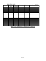
B. Inspections
Inspection shall be made in accordance with ch. 145.20, Wis. Stats. and s. SPS 383.26, Wis. Adm. Code.
The inspection form on the following two pages may be used. The inspection of the system installation
and/or plans is to verify that the system at least conforms to specifications listed in Tables 1 - 3 of this
manual.
42 of 44
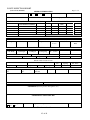
POWTS INSPECTION REPORT
(ATTACH TO PERMIT)
Page 1 of 2
GENERAL INFORMATION
City
Village
Town of
Permit Holder’s Name
State Plan ID No.
Tax Parcel No.
County
Sanitary Permit No.
Property Address if Available
TREATMENT COMPONENT INFORMATION
SETBACKS (FT)
TYPE
MANUFACTURER
CAPACITY
P/L
WELL
WATER
BLDG.
VENT
AND MODEL NUMBER
LINE
SEPTIC
DOSING
AERATION
HOLDING
FILTER
PUMP / SIPHON INFORMATION
Manufacturer:
Model No.
Demand in GPM
TDH - Design
FORCE MAIN INFORMATION
FRICTION LOSS (FT)
Length
Diameter
Dist. To Well Component Head Force Main
Vert. Lift
TDH - As
Losses
Built
TYPE OF COMPONENT:
Cell Width
Cell Length
SOIL ABSORPTION COMPONENT
COVER MATERIAL:
Cell Depth
Cell Spacing
No. of Cells
LEACHING CHAMBER OR UNIT
Manufacturer
SETBACK INFO. (FT) Property Line
Bldg.
Well
DISTRIBUTION COMPONENT
Elevation data on back of form
Header / Manifold
Distribution Lateral(s)
Length
Dia.
Depth over center of
cell:
Model No.
Water Line
Orifice
size
Orifice
Spacing
Dia.
Spacing
SOIL COVER
Depth over edge of
Depth of Cover
Texture
Seeded / Sodded
cell:
material
DEVIATIONS FROM APPROVED PLAN
OHWM
Obs. Pipes
Inst. & No.
Length
Mulched
DATE OF INST. DIRECTIVE:
DATE OF ENFORCEMENT ORDER:
DATE OF REFERRAL TO LEGAL COUNSEL:
COMMENTS (Persons present, discrepancies, etc.)
COMPONENTS NOT INSPECTED
Plan Revision Required
Yes
No
Date:
Signature of Inspector:
Sketch on other side
43 of 44
Cert. Number
ELEVATION DATA
Point
Back
Height of
sight
instrument
Page 2 of 2
Foresight
Elevation
Comments
Bench mark
Bldg. Sewer
Tank inlet
Tank outlet
Tank inlet
Tank outlet
Dose tank
inlet
Bottom of
dose tank
Dist. lateral 1
System elev. 1
Dist. lateral 2
System elev. 2
Dist. lateral 3
System elev. 3
Grade elev. 1
Grade elev. 2
Grade elev. 3
SKETCH OF COMPONENT & ADDITIONAL COMMENTS
44 of 44