1
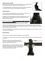
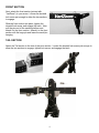
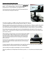
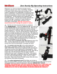
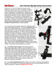
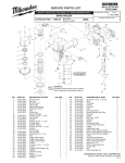
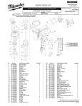
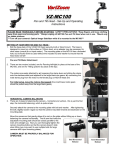
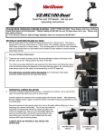
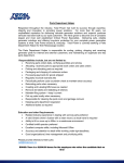
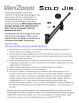
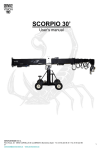
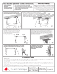
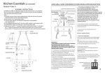
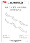
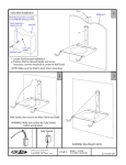
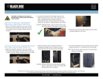
VZ-SnapCrane-9
Professional Modular
Camera Crane
Instruction Manuall
For a video tutorial “SnapCrane Build, Design and Assembly”, go to YouTube:
http://www.youtube.com/watch?v=hITbSn4ge-w
Please read the instruction manual thoroughly before operating your Crane system for the first time to
avoid injury or damage to the unit.
The durable construction of the SnapCrane makes it an excellent long-term investment, but its
precision design also means that you must exercise care in the storage, transport, and operation of
the unit to ensure optimal long-term performance.
Always exercise caution when operating the SnapCrane to avoid collisions with people,
objects, and power lines.
Do not operate in windy conditions.
Dolly is for setup, not for freely rolling the loaded crane around.
1
Parts List
Crane Arm Sections
1) Tail Section (short) w/ sliding micro-adjust counterweight
2) Pivot Section w/ half-moon shaped brake plate
3) Front Section (short) w/ “VariZoom” Logo
Support Sections
4) Camera Platform
5) Pan/Tilt Mounting Base for Crane Arm (“fulcrum”)
6) Tripod
7) Dolly
Cables (individually labeled)
10) Cable 3 (black)
11) Cable 4 (black)
Other Parts
12) Weight Bar (24” long stainless rod)
13) Plate Adapter (round, domed)
14) Braided Sleeving (for video/power cables)
SNAPCRANE MODE GUIDE
Compact Mode (front pivot hole, use black cable 4)
Arm Sections used: Front and Pivot sections only
Camera capacity: up to 50lbs.
Unit weight: 36 lbs.
Folded length: 55”
Overall length: 7’3”
Distance from tripod to camera: 5’8”
Vertical movement / Max Height: 8’ / 9’9”
Mid-Size Mode (rear pivot hole, use black cable 3)
Arm Sections used: Front, Pivot, and tail sections only
Camera capacity: up to 50lbs
Unit weight: 46 lbs.
Folded length: 55”
Overall length: 9’3”
Distance from tripod to camera: 6’6”
Vertical movement / Max Height: 9’ / 10’9”
***One hardware set supplied for all 5 black cable lengths. To switch hardware: pull the Quick Release pins
and remove the hardware from the cable, then attach to the appropriate-length cable.
Note: Vertical Movement is measured to camera platform, while “Max Height” is measured to overslung MC100 platform
2
TRIPOD & DOLLY SETUP
Before assembling your crane, make sure the dolly is on a completely flat,
level surface. Insert the tripod feet into the dolly receivers.
For maximum stability, extend the tripod feet so they snugly fit toward the
outer edge of the receivers and the spreader is flattened out.
PAN/TILT BASE
First, you will need to attach the base unit to the tripod. Unscrew the
base mounting knob and insert the base into the tripod.
Re-attach the base mounting knob securely, making sure the base is
seated correctly. Check the bull’s-eye level and adjust the tripod
leveling feet as necessary.
Position the dolly/tripod –***To prevent toppling, ONLY push at the
base of the legs (not up high)*** Based on the crane configuration,
you can estimate how much of a radius you will need to operate.
Reposition the dolly/tripod based on your situation, lining up a forward-pointing tripod leg with the
crane’s forward rest/default direction (this will maximize stability). For safety, engage the dolly wheel
brakes before continuing assembly.
Pull both T-handle pins out by pressing in on the blue button and pulling out on the t-handle. Let the
pins hang by their lanyards.
Pivot Section
The pivot section is the sub-section that attaches to the pan/tilt base.
To install the pivot section of the crane, slide it into place between the arms of the base, aligning the
pivot holes.
Make sure the brake knob and brake plate (halfmoon) are on the same side so the brake plate will
slide into the clamping mechanism.
Align the hole on the pivot section with the hole right
above the brake knob on the base. While depressing
the button, slide the thicker t-handle pin all the way
through the base and pivot section.
3
FRONT SECTION
Next, attach the front section (printed with
“VariZoom”) to your crane. Loosen the dovetail
lock screw just enough to allow the two sections
to engage.
Slide the front section into place, tighten the
dovetail lock screw, and engage the latch. Now
pull the pins out of the camera platform and
attach it to the front section. Attach it to the front
section with the large pin and leave the small pin
hanging.
TAIL SECTION
Attach the Tail section to the rear of the pivot section. Loosen the dovetail lock screw just enough to
allow the two sections to engage, tighten lock screw, and engage the latch.
4
Camera Leveling Cables (black cables)
Select the appropriate black cable according to the mode guide on
page 2. At the camera platform, slide the quick-release pin
through the eye of the turnbuckle on the selected cable.
Run the other end of the cable to the Pan/Tilt base and slide its
quick-release pin through the cable eye.
.
Counterweighting and Mounting Remote Head & Camera
Slide the weight bar through the hole at the back end of the tail section. There is a notch in the center
of the weight bar. Use the stainless steel thumbscrew at the back end of the tail section to engage
this notch and prevent the weight bar from accidentally sliding out when adding or removing weights.
Run all video and remote cables and loosen the tilt brakeGradually add weight until the crane just
begins to float. Using the aid of a helper or stand to hold the crane arm up, mount your remote head
and camera securely.
When attaching a remote head, use the dual-purpose plate adapter
to work with either 100mm half-ball mounts or a flat-base mount.
The most common method of attachment is underslung (shown
right). The remote head can also be overslung by reversing the
plate attachment.
Now that the camera platform is fully loaded with the remote head
and camera, tighten the black cable turnbuckle until the camera
platform is level.
Continue gradually adding counterweights to the weight bar until the crane is just short of balanced,
and then add your remote controls as the final “counterweight.”
Use the sliding micro-adjust counterweight to fine tune the balance.
When fully balanced, the SnapCrane should float in position, i.e., it should rise and fall with minimal
effort.
5
*** Warnings:
When disassembling the crane, NEVER pull the camera off first. This could cause the crane to catapult up and
topple, creating serious danger to nearby people. Always support the front end of the crane with a stand or chair
of some kind and gradually remove weights. Once you’ve removed enough weight, then you can remove your
camera.
The dolly is intended for initial setup on completely flat, smooth, level surfaces – not for free rolling of the loaded
crane. Any time you move the dolly, you should always push at a low point on the legs, as pushing at the top
can more easily lead to toppling.
Do not roll the fully loaded crane around. Too many unknown factors could create instability and potentially lead
to collisions and/or toppling– severe safety hazards. For this reason, we do not recommend rolling the loaded
crane around, especially outdoors.
6