1
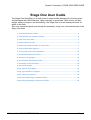
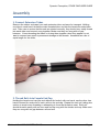
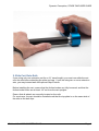
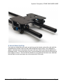
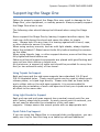
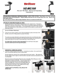
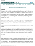
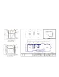
Dynamic Perception Stage One User Guide Dynamic Perception, STAGE ONE USER GUIDE Stage One User Guide The Stage One Slider/Dolly is a multi-function camera slider designed for shooting video and timelapse with dSLR cameras, either manually or motorized. With a focus on lightweight, ease of transport, and extensibility, the Stage One is an all-around performer for artists in the field. This user manual will guide you through the assembly, setup, use, and maintenance of the Stage One slider. 1. Connect Extension Tubes ................................................................................... 4 2. Thread Rails Into Female End Cap ...................................................................... 4 3. Slide Cart Onto Rails .......................................................................................... 5 4. Attach Male End Cap .......................................................................................... 6 5. (Optional) Compress Rails to Install Cart ............................................................ 7 6. Snap In Mid-‐Span Supports ................................................................................ 7 1. Locate and Count all Components .................................................................... 12 2. Install Motor Onto Cart Plate ........................................................................... 13 3. Remove Cart Upright ....................................................................................... 14 4. Install Pulley Onto Motor Shaft ........................................................................ 15 5. Assemble and Install Idlers ............................................................................... 16 6. Re-‐Install Upright ............................................................................................. 17 Using Tripods for Support .................................................................................... 22 Using Light Stands for Support ............................................................................. 22 Quick Table-‐Top Support ..................................................................................... 22 Underslung Shooting as a Manual Slider .............................................................. 24 Underslung Shooting as a Motorized Slider .......................................................... 24 Slidetrack© - WWW.SLIDETRACK.NO Page 2 Dynamic Perception, STAGE ONE USER GUIDE Maintenance and Care 1. 2. 3. 4. 5. 6. 7. 8. 9. Always ensure that Stage One parts are clean and dry before storage, assembly, or transport Keep rubber caps on both ends of extension tubes when in storage and transport Do not attempt to thread any parts together if threads are dirty or damaged Do not store for extended periods of time with belt installed and tensioned Wipe down rails with a clean, soft cloth before using For long life, avoid use in rain or very dusty environments Bearings are sealed and are not user-serviceable, do not attempt to lubricate them Clean components with damp cloth and mild soap and dry completely. Do not use solvents or cleaning products with abrasives to clean the Stage One or any part. Ensure that cart wheels are clean and free of debris before assembly Slidetrack© - WWW.SLIDETRACK.NO Page 3 Dynamic Perception, STAGE ONE USER GUIDE Assembly 1. Connect Extension Tubes Remove the rubber end caps from each extension tube and save for transport. Holding one tube in each hand, thread the male threaded tube end into the female threaded tube end. Take care to ensure that threads are started correctly, they should very easily thread into each other and connect snug together. Make sure they are snug with no gap between. Cross-threading the tubes or forcing them together when they appear to not want to connect can result in permanent damage to the threads. Assemble two rails of equal length for the slider, 2. Thread Rails Into Female End Cap Holding the female end cap (the end without the knobs) with one hand, use the other free hand to thread the male end of each rail into the end cap. Repeat for each rail, taking due caution to avoid cross-threading or attempting to force the threads to seat. Each rail should thread in easily with no force and end up snug with the female end cap. Make sure they are snug with no gap between rail and end. Slidetrack© - WWW.SLIDETRACK.NO Page 4 Dynamic Perception, STAGE ONE USER GUIDE 3. Slide Cart Onto Rails If you using only one extension set (for a 21" travel length), you must now slide the cart onto the rails before attaching the male end cap. If you are using two or more extension sets, you may instead wait until optional Step 5 below. Before installing the cart, ensure that the friction brakes are fully loosened, and that the friction brake knobs are at least 1/2" out from the cart uprights. Ensure that all wheels are correctly located on the rails. For most uses, the cart should be installed such that the top plate is on the same side of the rails as the belt clips. Slidetrack© - WWW.SLIDETRACK.NO Page 5 Dynamic Perception, STAGE ONE USER GUIDE 4. Attach Male End Cap You may now attach the male end cap by lining up the female ends of the rails with the threaded posts inside of the end cap, and turning the knobs evenly. Don't attempt to tighten one knob down fully before moving to the next. Each knob must be tightened or loosened evenly. If one knob fails to turn, reverse whatever you just did on the previous knob slightly to free it. Ensure that the knobs are snug and secure before use, and that the belt clips on both end caps are on the same side of the rails. Slidetrack© - WWW.SLIDETRACK.NO Page 6 Dynamic Perception, STAGE ONE USER GUIDE 5. (Optional) Compress Rails to Install Cart When using two or more extension sets, you may find it easier to install the cart after having fully assembled the rails, by gripping both sides of the rails at the center of the slider, compressing with your hands and then slipping the cart on, one side at a time. With practice, most users will find this the easiest way to install the cart in the field. 6. Snap In Mid-‐Span Supports For best results, one mid-span support should be used at every rail tube intersection. To install the mid-span supports, bring the mid-span support up from below the rails, and press upwards until it snaps firmly into place. Be very careful to keep your hands and fingers clear of the intersections between the mid-span support and the rails to prevent injury. Ensure that the cart is clear of the area you are installing the mid-span support, otherwise it may be difficult to snap into position. Slidetrack© - WWW.SLIDETRACK.NO Page 7 Dynamic Perception, STAGE ONE USER GUIDE To disassemble, simple repeat these steps in reverse, pulling downwards on the mid-span supports to release them. Slidetrack© - WWW.SLIDETRACK.NO Page 8 Dynamic Perception, STAGE ONE USER GUIDE Packing for Travel To pack the Stage One for transport, disassemble the unit completely according to the assembly instructions. The following tips will help to ensure a long life for your slider, and aid in preventing damage during transport: 1. Always pack the rail tubes separate from the cart, endcaps, and mid-span supports to prevent scratching and gouging of the rails 2. Always replace the rubber covers over the end of the rail tubes to prevent damage to the threads, and to keep them clean 3. Ensure that belt clip bolts are tightly attached before packing, to prevent loss of belt clips during transport 4. Ensure that friction brakes are fully threaded into the cart before packing, to prevent loss of friction brakes during transport 5. Keep rail tubes in a package with a firm exterior to prevent bending of the tubes 6. Never travel with rail extensions connected together to prevent bending of the tubes or damage to the threaded couplers 7. For best results, always transport the Stage One in its original packaging Slidetrack© - WWW.SLIDETRACK.NO Page 9 Dynamic Perception, STAGE ONE USER GUIDE Manual Slider Operation The basic Stage One system can operate as a standard, hand-pushed slider for smooth video shooting. The included friction brakes add additional friction to make it easier to make smooth starts and stops when pushing the camera by hand. It is not required to purchase a DC Motor Upgrade Kit to use the Stage One as a manual slider. If you have installed a DC Motor Upgrade Kit, always completely remove the belt before attempting to use as a manual slider! To use the Stage One as a manual slider, first attach your preferred camera mounting solution, such as a ballhead, to the cart using the provided hardware. After having mounted the cart to the slider, now mount your camera and adjust the position to the desired framing. Adjust the friction to the desired level by tightening the friction brake knob on each side of the cart equally. Note that the friction brakes will not completely stop the cart from moving under load. The heavier the camera, the more friction you should apply for the best results. Using your hand, push the cart from the desired starting point to the desired end point. Slidetrack© - WWW.SLIDETRACK.NO Page 10 Dynamic Perception, STAGE ONE USER GUIDE Slidetrack© - WWW.SLIDETRACK.NO Page 11 Dynamic Perception, STAGE ONE USER GUIDE Motorized Slider Operation Using a DC Motor Upgrade Kit, you can create beautiful timelapse videos with the Stage One and the MX2 Motion Controller. For information on how to use the MX2 Motion Controller, see the MX2 User Guide. DC Motor Upgrade Kit Installation The following instructions will guide you through installing the DC Motor Upgrade Kit on your Stage One. 1. Locate and Count all Components 1x. Hex Tool 1x. Motor with installed bolts, spacers, and bolt retainers 2x. Idler assemblies 1x. Pulley Slidetrack© - WWW.SLIDETRACK.NO Page 12 Dynamic Perception, STAGE ONE USER GUIDE 2. Install Motor Onto Cart Plate a. Place the motor on the top plate of the cart, aligning the bolts with the bolt holes and the shaft with the large shaft through-hole. b. Using the provided hex tool, tighten down the bolts by starting at one corner, then moving to the opposite corner, until all four bolts have been started. Do not tighten down any bolts fully until the all four bolts have been started. Slidetrack© - WWW.SLIDETRACK.NO Page 13 Dynamic Perception, STAGE ONE USER GUIDE 3. Remove Cart Upright a. Turn cart over and using the provided hex tool, remove the upright nearest the motor. Note: you may find it easiest to remove the upper wheels from the upright first. Slidetrack© - WWW.SLIDETRACK.NO Page 14 Dynamic Perception, STAGE ONE USER GUIDE 4. Install Pulley Onto Motor Shaft a. Slide the pulley onto the shaft, with the hub facing towards the plate. Space the hub face approximately 1/8" from the bottom of the cart plate, ensuring that one of the setscrews is at the center of the flat on the shaft. Note: the cardboard card from the hex tool can be used as a shim for spacing the pulley, simply lay it flat against the plate bottom and let the pulley rest on it. Slidetrack© - WWW.SLIDETRACK.NO Page 15 Dynamic Perception, STAGE ONE USER GUIDE b. Using the smallest hex tool, tighten the set-screw at the center of the shaft flat c. Using the same hex tool, tighten the set-screw at the side of the shaft 5. Assemble and Install Idlers a. Locate the mounting hole for each idler near the motor shaft b. Start each idler bolt into a mounting hole and tighten with the included hex screw Slidetrack© - WWW.SLIDETRACK.NO Page 16 Dynamic Perception, STAGE ONE USER GUIDE 6. Re-‐Install Upright a. Place the upright back on the bottom of the cart, and use the supplied hex tool to re-install the upright. Make sure to tighten down the bolts as tight as you can. If you removed the wheels, re-install them after attaching the upright to the cart. Slidetrack© - WWW.SLIDETRACK.NO Page 17 Dynamic Perception, STAGE ONE USER GUIDE Preparing the Slider for Motorized Operation To prepare the Stage One for Motorized Operation, you will need to ensure that the cart is correctly installed, and then attach the belt. The cart must be oriented such that motor is on the same side of the rail as the belt guides. The following photograph illustrates the correct orientation: After installing the cart, you will now need to attach the belt. Starting at one end, loosen the belt clip and install one end of the belt into the clip such that the belt teeth and the clip teeth meet each other. Slide the belt clip so that it is closest to the belt guide, and then tighten the clip bolts tightly with your fingers. Guide the belt out and around the belt guide, and then to the cart. Slidetrack© - WWW.SLIDETRACK.NO Page 18 Dynamic Perception, STAGE ONE USER GUIDE Feed the free end of the belt around the nearest idler and pull all of the slack belt through. Guide the loose end of the belt through the space between the idler and the pulley, and then around the pulley. Now, feed the belt fully around the pulley, and behind the second idler. With your free hand, push the cart away from the end of the slider where the belt is already clipped in to, to tension the belt on that side of the cart. Slidetrack© - WWW.SLIDETRACK.NO Page 19 Dynamic Perception, STAGE ONE USER GUIDE Prepare the remaining belt clip by loosening it, and sliding it in closest to the belt guide. Keeping some tension on the belt, guide it around the outside of the last belt guide, and slide it into the belt clip. Tighten the belt clip approximately half way, and with one hand, push the clip away from the guide with your thumb to tension the belt, and then tighten the clip with your other hand. If the belt has gained some slack on the opposite side of the cart during this process, you may loosen that belt clip slightly and push it away from the belt guide before tightening it again to remove this slack. Slidetrack© - WWW.SLIDETRACK.NO Page 20 Dynamic Perception, STAGE ONE USER GUIDE The belt should be fairly taught, but not extremely so, during operation. On longer runs, some slack will be present in the belt. For those on a budget, it is recommended to use one length belt for your longest setup, rather than cutting it to different lengths, and let the extra belt hang off of the end of the track, or secure it with a rubber band. Slidetrack© - WWW.SLIDETRACK.NO Page 21 Dynamic Perception, STAGE ONE USER GUIDE Supporting the Stage One Failure to properly support the Stage One may result in damage to the Stage One, your equipment, or nearby persons. Always properly support the Stage One when in use. The following rules should always be followed when using the Stage One: Never support the Stage One by leaning it against another object, the load may shift during the shoot and cause the slider to topple over. Always lash it to any item it is leaning against with a cord, rope, or other device to secure it in place. When using century mounts, such as with light stands, always tighten down the included C-Stand mount bolts fully before loading the camera on the slider When using tripods, legs, or other support devices, ensure that they are fully tightened down before use Make sure that all support components are placed with good footing and may not lose their stance or topple over At a minimum, a support of some sort should be provided for every four feet (or two extension sets) of free travel. Using Tripods for Support Both end caps and the mid-span supports have standard 1/4-20 and 3/8-16 threaded holes. These mount points can be used to attach quick release plates, or tripod legs directly. Please note that as these holes are to either side on the mid-span supports, it is recommended to alternate the orientation of each mid-span such that your tripods are not all offset to the same side. Using Light Stands for Support Each end cap and mid-span support has a central mount point for use with Century stand style mounts. As each mount point is centered, you do not need to alternate the orientation of the mid-span supports. Always secure the mount points with an appropriate bolt. Quick Table-‐Top Support If you are using the Stage One in a manual slider configuration, you can easily use it up to four feet long on a table top without additional Slidetrack© - WWW.SLIDETRACK.NO Page 22 Dynamic Perception, STAGE ONE USER GUIDE support by installing the cart upside down on the rails, such that the belt clips are facing down, away from the cart. In this way, you may simply place the slider on a table top, or other level surface without additional supports. Slidetrack© - WWW.SLIDETRACK.NO Page 23 Dynamic Perception, STAGE ONE USER GUIDE Shooting Underslung The Stage One is capable of shooting underslung, such that the camera is located below the track. To do this, you will need to support the rig properly. Please note that the total length of the rail will be limited to 42" as you can only support the Stage One from the ends when shooting underslung. You MUST use at least one mid-span support for every extension section on the Stage One when shooting underslung. Failure to use the correct number of mid-span supports may result in the rails compressing together, and the cart slipping off of the rail, causing damage to your camera. Underslung Shooting as a Manual Slider This is the easiest way to shoot underslung. When manually pushing the cart you only need to reverse the orientation of the cart so that it is installed with the belt clips on the opposite side of the rail. Now, you may use the standard mount points on the end caps to support the unit. Underslung Shooting as a Motorized Slider To shoot underslung in a motorized configuration, you will need to move two mid-span supports to the top of the rail (such that they are on the same side as the cart), and push them all of the way out to the ends of the rail, or wherever you want the limit of travel to be. Mount your supports as normal, and flip the slider over. # Slidetrack© - WWW.SLIDETRACK.NO Page 24