1
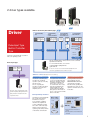
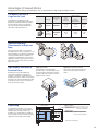
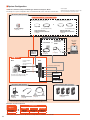
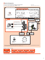
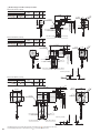
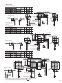
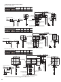
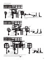
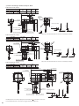
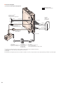
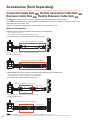
● Connection Diagram
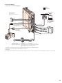
◇ Connection to Peripheral Equipment
Included
Sold separately
24 VDC Power Supply✽3
Be sure to connect
when using an electromagnetic brake.
Control Module OPX-2A
Data Setting Software
MEXE02
or
24 VDC
Connect to CN1
To connect PC with driver,
please use communication
cable for the Data Setting
Software (CC05IF-USB,
sold separately).
GND
Connect to CN1
Cable for Electromagnetic Brake✽1
Cable used to connect
electromagnetic brake and driver.
Connect to CN4
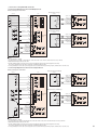
Output signal : Connect to CN9
Connect to CN2
Cable for Motor✽1
Cable used to connect
motor and driver.
Input signal : Connect to CN8
PE
Sensor signal : Connect to CN5 Controller✽2
Connect to CN3
PE
Circuit Breaker✽2
Power Supply Voltage✽2
Single-Phase 100-120 VAC 50/60 Hz or Ground Fault Interrupt Circuit
Single-Phase 200-240 VAC 50/60 Hz This must be placed, in order
to protect wiring on primary
side.
Noise Filter✽2
Use a noise filter to eliminate noise.
This can help to reduce noise generated
by Power Supply or Driver.
✽1 Each product comes with a motor cable 3 m (9.8 ft.) long. Different lengths and flexible cables are available (sold separately).
When wiring the motor and the driver, keep a maximum distance of 20 m (65.6 ft.).
✽2 Not Supplied.
✽3 Not Supplied. If the wiring distance between the motor and driver is extended to 15 m (49.2 ft.) or longer by using an accessory cable (sold separately), the 24 VDC±4% specification applies.
45