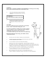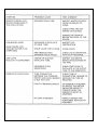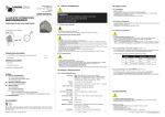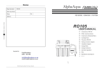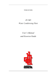
1
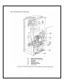
Instruction Manual
2 & 4 litre per hour water stills
READ BEFORE USE!
2
This Manual contains different levels of warnings and
cautions in order to ensure you are alerted to any
potential hazards when installing or operating the
equipment. These are categorised as follows:
WARNING:
APPLIES WHEN THERE IS A POSSIBILITY
OF PERSONAL INJURY
CAUTION:
Applies when there is a possibility of damage to the equipment.
NOTE:
Alerts the user of the manual to pertinent facts and conditions.
Symbols
Various symbols are used on the product as follows:
Electrical Safety
Earth Symbol
3
Fistreem International Ltd
Health and Safety at Work
Fistreem International Ltd is required under the Health and Safety at work, etc. Act, 1974 and
other UK legislation as designers, manufacturers, suppliers and importers of articles for use at
work to ensure that, as far as is reasonably practicable, articles which we design, produce,
supply or import are safe and without risk to health.
We are required to provide information on the safety and handling precautions to be observed
when installing, operating, maintaining and servicing our products. Such advice is contained in
this manual.
We are also obliged to update this information should circumstances change and to operate a
system to this end.
We should also like to point out, however that you as users have an important
responsibility in the provision and maintenance of safe working practices and
conditions.
Accordingly, we draw the following matters to your attention:
1.
This apparatus should only be used as intended and within its design
parameters by suitably qualified and trained personnel who have read
and understood the relevant sections of this manual.
2.
This manual should be readily available to such personnel at all times.
3.
In addition to that which is written in the manual, normal common-sense
safety precautions must be taken at all times to avoid the possibility of
accidents. Particular care is required when working with apparatus at
high temperature or pressure.
4.
Installation, maintenance, repairs and servicing should only be carried
out by an approved engineer, and connection to electrical supplies
should only be carried out by suitably trained personnel.
TECHNICAL SUPPORT, WARRANTY SERVICE AND MAINTENANCE
UK customers; if you are in any doubt whatsoever regarding the correct use of this apparatus,
or if you require any technical data or assistance, please contact the Fistreem International
Technical Support Department at;
Fistreem International Ltd
Monarch Way
Belton Park
Loughborough
Leicester LE11 5XG
Telephone
Fax
E-mail:
+44 (0) 1509 224613
+44 (0) 1509 260210
[email protected]
OVERSEAS CUSTOMERS: Should contact their local Distributor..
ELECTRICITY SUPPLIES: Voltage and frequency
This apparatus is offered and labelled for one, or for a choice of two or more voltage ranges
and, where necessary, different frequencies of mains supply. Fistreem International Ltd does
not accept any responsibility for the operation of any such apparatus should it be connected to
electricity supplies which are normally outside, or vary outside, the stated voltage and
frequency values for which it is designed, nor for any consequential loss, damage or injury,
howsoever caused.
Read This Before Use!
4
CALYPSO Mk 1 GLASS STILL
April 2010
Instruction manual Z01436
MANUAL CONTENTS
Page No.
Warnings, Cautions, Notes
Health and Safety at Work
Introduction
General Description
Glassware safety
Care of product
Electrical safety
Pre-Installation
Service requirements
Positioning
Unpacking instructions
List of contents
Installation Procedures
Fixings, Water supply connection
Drain connection
Distillate outlet pipe fitting
Fitting heaters
Reservoir level control
Mounting instructions
Operating Procedures
Initial setting up
Normal operation
Boiler draining
Pre-treated Water Supply Procedures
Introduction
Plumbing
Electrical
External connections from
existing pre-treated feed supply
Operation from existing pre-treated
feed supply
Operating procedures
Maintenance
Boiler Cleaning Procedure
Troubleshooting Guide
Parts List
Electrical Wiring Diagram
Circuit Diagram
Water Flow Diagrams
Technical Characteristics
3
4
9
9
10
10
10
11
11
12
12
12
13
13
13
14
15, 16
17
17
18
18
19
19
20
21
21
22,23
24, 25
26
27
28
29, 30
31
5
6
7
8
1. INTRODUCTION
The Calypso Still has been designed to produce nominally 2 or 4 litres per hour of high quality
distilled water.
It is a simple cabinetised glass distillation unit incorporating a unique cyclonic effect
condenser vapour trap.
Supervision is required for various aspects of operation with the Calypso. However, an overtemperature cut-out will shut the still down should the boiler water level become insufficient
leaving the heaters exposed.
The Calypso is supplied with a reservoir level sensor which can be fitted to a suitable storage
container, to provide automatic operation of the still.
The Calypso is designed to be used with either raw ( potable ) tap water or with pre-treated water.
The unit can be either wall or bench mounted. A wall mounting bracket is provided, however,
suitable fasteners should be provided by the user. See section 4.2, page 13.
2.
GENERAL DESCRIPTION
The Calypso has been designed to be simple to operate and maintain.
It can be fed from a potable water supply or alternatively the boiler can be supplied from a pretreated water supply if preferred. It is recommended that if the Still is to be operated in a locality
that has a known hard water supply, then a pre-treated supply may be considered to eliminate the
need for regular de-scaling procedures.
The Still consists of a glass boiler retained in a metal cabinet by two large clips. The glass
condenser and constant level device are connected to the boiler. The cabinet has a smart acrylic
front cover with magnetic fastener.
The electrical controls are mounted in an enclosed compartment at the side. The top cover can be
removed to enable the silica sheathed heaters to be installed into the boiler.
A solenoid valve, fitted with a flow restrictor, controls the input water flow to the unit. Where the
boiler is to be fed with pre-treated water, using the optional pre-treated water kit, a second valve is
used to control this supply.
An over-temperature cut-out is positioned in the back of the boiler. Should an over-temperature
condition occur, this switch will need to be manually reset after the Still has cooled.
The unit is operated by a mains switch. When the mains switch is ON the solenoid valves(s) are
energised allowing water to flow. When the boiler is full and water is flowing to drain the heater
switch should be turned ON energizing the heaters. If the heaters are turned on before the boiler has
filled the over-temperature cut-out will activate.
9
2.1
GLASSWARE SAFETY
Like all laboratory glassware assemblies, after an extended period of use, Water Stills may suffer a
reduction in wall thickness caused by the continual process of solution attrition.
In the unlikely event that failure occurs it may be sudden, therefore, it is wise to be cautious when
servicing or handling equipment, and to periodically check the thickness of the Still's boiler.
It is important to site Water Stills in a safe location, such that personnel are not endangered by
the spillage of boiling water or broken glass.
In operation it is strongly recommended the door on Calypso is kept closed. By doing so, any
spillage of water or failure of the glassware is likely to be contained in the Still's cabinet.
2.2 CARE OF PRODUCT
The product is finished in epoxy paint for durability.
In order to keep the paint surface clean and free of stains, regular wiping with a cleaning agent is
recommended. Avoid the use of solvents and coarse materials.
2.3 ELECTRICAL SAFETY
This equipment should be connected to the electricity supply in accordance with the IEE wiring
regulations or your local electrical installation regulations.
Before connecting this apparatus to the electricity supply, check the information given on the
apparatus rating plate and ensure that:
(a)
(b)
(c)
Your supply is single phase a.c. (alternating current) of the stated
frequency with neutral nominally at earth potential.
Your supply voltage is within the stated range.
The current rating is within the capacity of your supply outlet.
WARNING: THIS APPARATUS MUST BE EARTHED
The wires in the mains cable are coloured in accordance with the following code:
Green/Yellow or Green
Earth
Blue
Neutral
Brown
Live
IMPORTANT: Consult a qualified electrician if in any doubt or if the supply system has any of the
following:
*
*
*
*
No earth
A colour code different from the above
Reversible plugs
Supply and return leads that are both above earth potential
10
3.
PRE-INSTALLATION
Before starting to install and operate the Calypso, please read carefully and observe the following
points.
3.1 Service Requirements
Power Supply:
120 Volt, 220 Volt or 240 Volt, 50-60Hz single phase
Both the 220Volt and 240Volt versions of the 2 litre/hour Still (1800W)
require a 10 Amp fused supply, via a plug and socket
The 220Volt version of the 4 litre/hour Still (3000W) requires a 15 Amp
fused supply, via a hard wired system.
The 240Volt version of the 4 litre/hour Still ( 3000W) requires a 15 Amp
fused supply, via a plug and socket.
The 120Volt version of the 2 litre/hour Still requires a 20 Amp fused
supply, via a plug and socket
The Still will function at both 50 / 60 Hz.
.
WARNING:
CHECK THAT THE VOLTAGE DESCRIBED
ON THE RATING LABEL CONFORMS TO
THE POWER SUPPLY YOU HAVE
AVAILABLE.
ALSO CHECK THAT THE VOLTAGE
MARKED ON THE HEATERS IS
COMPATIBLE.
CONTACT YOUR DEALER IF THE
VOLTAGES DO NOT MATCH OR YOU ARE
UNSURE AS TO THEIR SUITABILITY.
Feed Water Supply:
Flow rate: at least 0.5 litre/min (2 litre model)
or at least 1 litre/min (4 litre model)
Pressure: 10-80 psi ( 70 – 560 kPa )
Pre-Treated Supply:
Flow rate: more than 2 litres/hour (2 litre model)
or more than 4 litres/hour (4 litre model)
Pressure: at least 2 psi
Drain:
The sink or drain should be below the level of the Still’s drain
outlet. The drain should be atmospherically vented.
11
CAUTION : The Pre-treated feed rate should always slightly exceed the
distillate output rate. Failure to do so will cause the boiler water level to
fall and the still will shutdown.
POSITIONING
It is recommended the Still is located within easy distance of services ( feed water,drain water and
electrical supply ) to avoid unnecessary long runs of pipework and cabling.
3.2 Environmental Conditions
The Still is designed to operate safely under the following environmental conditions:
- Indoor use.
- Altitude up to 2000 metres.
- Ambient temperatures between +5°C and +40°C.
- Supply voltages not to exceed ± 10% of nominal voltage.
- Maximum humidity, 80% at 31°C, decreasing linearly to 50% at 40°C.
- Pollution degree 1.
3.3 UNPACKING
Caution :
The Still, although not particularly
heavy, is an awkward size, it is
recommended that at least two
people are involved in all lifting
operations.
When lifting keep the door in place, any other face of the Still can be used to obtain a hold on the
Still.
Carefully remove the Still and the accessory pack from the box. Inspect for breaks or missing parts.
Do not throw away any packing, until the Still is assembled and installed.
3.4 The accessory pack contains one each of the following :
- Wall mounting bracket
- Inlet water hose assembly
- Glass distillate elbow
- Reservoir level sensor
- Length of silicone rubber tubing (distillate)
- Length of silicone rubber tubing ( for conversion to pre-treated feed – optional )
- Length of PVC tubing (pressure sensor)
- Acrylic door
- Heating elements (2)
- Small plastic funnel, for acid cleaning
12
INTERNAL PACKING
a.
In order to remove the internal packing and subsequently fit the heating elements it is
necessary to remove the top cover of the Still.
b.
Remove the acrylic front cover by lifting the cover upwards.
c..
Using a cross-head screwdriver, unscrew the four screws holding the top
cover in place.
d..
Remove the white foam packing pieces from the unit.
e.
Carefully remove the cardboard glass supports.
4. INSTALLATION PROCEDURES
4.1
Fixing
The Still may be either free standing or wall mounted. Where bench mounted, ensure the drain tube
is allowed a continual downward path to drain, free of any restrictions.
4.2
Wall Fixing
Fix the "J" shaped mounting bracket (accessory pack) to the wall using an adequate wall anchoring
method. Check the wall construction and select the most appropriate wall plug. Note the operational
weight of the unit is approximately 15kg (35bs).
Caution:
4.3
Contact your building maintenance personnel if you are unsure about either
the type of hardware fixings to use or the ability of the wall to support
this weight.
Water Supply Connection
Connect the water input hose to the rear screw thread connector on the right side of the Still.
Ensure that the internal screen filter is installed in between the male and female parts of the screw
connection.
Where a pre-treated water supply is to be used see section 6, page 20, 21.
4.4
Drain Connection
A length of flexible drain tube is supplied already fitted to the Still. Uncoil the tube and place it in
an open drain, sink or gulley; cut to length if required. Ensure
this hose is free of kinks and has an unrestricted gravity flow to drain.
It is advisable to run the drain hose below the mains water input hose to avoid any raising of the
drain hose as it exits the Still.
13
4.5
Distillate outlet pipe fitting
Fig. 3
Take the right angled glass distillate connector (4) and fit
the distillate tube (silicone rubber tubing) to the riffled
end. Connect this using the plastic screw fitting (3)
attached to the screw thread outlet of the condenser (1),
ensure that the PTFE disc (2) on the sealing washer is
facing outwards (towards the water).
Feed the distillate tube through the distillate port on the
right side of the Still.
Reconnect the plastic screw fitting onto the screw thread
outlet of the condenser, ensuring the PTFE
disc on the seal washer is facing outwards (towards
water).
14
4.6
FITTING HEATERS
WARNING:
ENSURE THE STILL IS DISCONNECTED FROM THE
POWER SUPPLY. THIS PROCEDURE IS NOT A USER TASK AND
MUST BE PERFORMED BY A QUALIFIED
ELECTRICIAN OR SIMILARLY COMPETENT PERSON.
CAUTION:
a)
Ensure that the heaters are the
correct rating for your Still by
comparing the markings on the
heater with those on the rating label.
Remove the electrical access panel on the right
side of the Still by removing the two retaining
screws.
WARNING:
AN EARTH ELECTRICAL
LEAD IS ATTACHED TO THIS
PANEL.
DO NOT REMOVE THIS LEAD.
b)
The two identical heating elements are fitted
into the top of the boiler by means of plastic
screw threaded unions.
c)
Unscrew and remove from the heater the
internally threaded part of the plastic union
and the split ring.
d)
Push the internally threaded part of the plastic
union initially onto the right side heater entry
port, followed by the split ring. See Fig 4.
e)
Carefully insert the heater into the entry port and
thread the two halves of the plastic union together
until hand tight. Be careful not to hit the glass
pocket ( contains the thermal cut –out ) in the
boiler.
NOTE: A smear of silicone grease on the tapered
surface of the nitrile rubber ring and on the union
threads greatly assists obtaining a tight joint.
15
To avoid nuisance tripping of the thermal cut- out it is important to equally space the
heaters from the boiler wall and the glass pocket of the thermal cut-out. This may be
achieved by rotating the heater prior to fully tightening the plastic unions.
f)
The heater cable should be fed through the hole in the electrical box ( upper right rear
corner ).
Repeat this procedure (c-f) for the other heater element.
g)
Feed both heater cables neatly into the electrical box and connect up as
indicated on the terminal block label. See Fig 5 .
Fig. 5 Heater Connections
NOTE:
This is a good time to check that the heater core is fully located at the bottom of its
sheath.
h)
To avoid any excess cable in the Still’s compartment, surplus cable
can be accommodated at the top of the electrical compartment.
j)
Refit the electrical compartment access panel and top panel
ENSURING THE EARTH WIRE IS CONNECTED and that screws are fully tightened.
k)
Re-fit the door
16
4.7 Reservoir level control
The pressure switch fitted to the unit is activated by the pressure of air in the sensor caused by the
rising level of the distilled water in the reservoir.
When the reservoir is full the pressure switch shuts off the electrical supply to the Still preventing
further distillation. After drawing water from the reservoir, the still will restart automatically.
The level sensor can be fitted to a variety of bottle caps or container lids.
CAUTION: Do not test this device by blowing down the tube, uncontrolled pressure
may damage the switch.
NOTE:
After switching off, up to l00 ml of water may continue to be delivered to the reservoir.
For this reason it is recommended that containers with long narrow necks are not used or an
overflow may result.
a.
Cut a 31 mm hole in the lid of the container and push the sensor into the hole from above.
The thickness of the cap should not exceed 16mm.
b.
If the container is airtight with the sensor fitted, a small vent hole should be made in the top
of the container near to the sensor.
c.
Feed the distillate tubing through one of the holes on either side of the Still and connect it to
the larger of the two connections on the level sensor.
d.
Fit the PVC tubing supplied, onto the small connection on the level sensor. Fit the other end
onto the pressure switch, this is a metal tube that protrudes from the right hand side of the Still.
.
•
NOTE: These connections must be airtight to ensure correct functioning.
4.8 Mounting instructions
The still can be bench mounted or fixed to a wall.
Where bench mounted, ensure the drain tube is allowed a downward path to drain free of any
restrictions.
If wall mounted, fix the mounting bracket to a substantial wall, using appropriate anchor hardware
CAUTION: The weight of an operating unit is approximately 15 kg.
Contact your building maintenance personnel if you are unsure about either the type
of hardware fixings to use or the ability of the wall to support this weight.
17
WARNING:
UNDER NO CIRCUMSTANCES SHOULD
ANY OF THE ACCESS PANELS BE REMOVED WHEN THE STILL
IS IN USE OR WHILE THE POWER-ON LAMP IS ILLUMINATED.
SERVICING SHOULD ONLY BE UNDERTAKEN BY QUALIFIED
PERSONNEL
5. OPERATING PROCEDURES
Normal operation of this Still does not involve the user with any of the internal workings of the unit.
In operation it is strongly recommended the door on the Calypso Still
is kept in place. By doing so, any spillage of
water or failure of the glassware is likely to be contained
in the Stills cabinet. It also prevents the user from
accidentally touching the hot glassware inside.
NOTE: If it is intended to run the Still on a pre-treated water supply please see Section 6 before
commencing.
5.1
Initial Setting Up
a.
Check the power switch is off.
b.
If the Still is connected to a reservoir, disconnect the distillate tubing between the
condenser and the distillate outlet, connect this outlet to a suitable drain. The initial output
may be contaminated with packing dust etc, and should not enter the storage tank, but
flushed away.
c.
Connect the Still to the power supply and switch on at the power outlet.
d.
Check the boiler drain valve to be sure it is in the closed position.
e.
Turn on the mains water supply. Check for leaks. Water will not flow into the
boiler at this stage.
f.
Switch the power switch ON. The white lamp should illuminate and water will begin to flow
into the boiler.
g.
Wait until the boiler has filled with water and is flowing over the constant level device
down to drain. This will indicate the level of water in the boiler is adequately covering the
heaters.
h.
Switch the heater switch ON. The green lamp should be illuminated.
18
CAUTION : If the heater switch is turned on before the boiler has filled, the thermal
cut-out will shut down the Still. The Still cannot be restarted until the switch has
cooled down and then manually reset by pressing the centre of the switch, visible next
to the electrical compartment ( fig 2 item 11 ). It will take about 15 to 20 minutes for
the cut-out to cool down.
i.
After a short time, distilled water will flow from the outlet.
Allow this to run to drain for 30 minutes, to flush out any contamination.
j.
Turn the still off.
k.
Reconnect the distillate tube between the condenser outlet and the
storage reservoir.
l.
Restart the still and check tor internal leaks.
m.
Replace the front cover.
5.2 Normal operation
Once the initial setting up has been carried out, for normal operation simply press the power switch
ON followed by the heater switch ON.
CAUTION: If the heater switch is turned on before the boiler has filled) the thermal cutout will shut down the still. The still cannot be restarted until the switch has cooled down and
then manually reset, by pressing the centre of the switch, visible next to the electrical
compartment. It will take about 10 minutes for the cut-out to cool down.
5.3 Boiler draining
The boiler need only be drained when the water starts to foam. It is recommended that the Still is
drained at least once a week prior to start up. The more frequently this is done, the cleaner the boiler
remains.
19
6.
6.1
PRE-TREATED WATER SUPPLY USING THE
PRE-TREATED CONVERSION KIT
Introduction
The Pre-treatment conversion kit allows the user to upgrade the Calypso from raw tap feed to pretreated water feed.
The still may be supplied with suitable treated water e.g. deionized, distilled or reverse osmosis
from the users existing supply.
Condenser water (tap water) is separated from the boiler (treated supply) for economy. It is
important to regulate the treated water to avoid wastage.
6.2 Plumbing
See fig 1 A, page 7.
Using the parts supplied in the pre-treated supply kit. Disconnect the supply tube from the
condenser outlet, and from the "T" piece. Disconnect the constant level device drain tube, cut tube
to fit the condenser drain tube with the "Y" piece. Ensure that the condenser outlet tube is the
correct length to allow fitting to the "Y" piece. This will allow waste condenser water to be piped
directly to drain.
The treated water supply tube should now be connected between the treated water solenoid valve
and the "T" piece.
6.3 Electrical
Remove the electrical compartment access panel (four screws).
Fit the solenoid valve supplied in the conversion kit in the blanked off hole adjacent to the existing
tap supply solenoid valve ( fig 2 ) page 8. The fixing method is the same. The wires fitted to the
treated water solenoid are at present unconnected.
Connect these to the terminal block as illustrated in fig. 5 page 16.
Refit the electrical compartment access panel.
6.4 External connections from a users existing pre-treated feed supply
a.
Connect the pre-treated water feed supply to the water input solenoid valve, using the
angled hose connector supplied.
b.
Turn on the treated water supply and check for leaks.
NOTE: The treated water must have a positive pressure, although a very low pressure (2 psi) is
acceptable.
20
6.5 Operation - from the users existing pre-treated feed supply
a.
Turn on the mains tap water supply to the Still.
b.
Turn on the treated water supply.
c.
Switch on the power supply to the Still.
d.
Press the Still's "ON/OFF" switch, the lamp will illuminate.
Tap water will flow through the condenser and be discharged to drain
.
When the treated water has filled the boiler and begins to flow to drain
via the Still's constant level device, switch on the heaters.
e.
f.
After a few minutes water will begin to boil and distillate will flow from the distillate
outlet.
NOTE: When the Still is switched off the boiler contents should not normally be drained..
6.6 Operating procedures
Once the above procedures have been completed and the appropriate input water flow rates have
been set, the operating procedures are as detailed in section 5, page 18.
7.
MAINTENANCE
Periodic inspection of connecting hoses, internal tubings,
connections and glassware parts is recommended to
ensure continuity of safe operation and avoiding
unnecessary leaks.
User should inspect any replacement parts to ensure
they are manufacturer specified parts.
21
8.
BOILER CLEANING PROCEDURE
When the Still is to be run off a potable( tap ) water supply routine de-scaling will be necessary to
maintain efficiency. In hard water areas it is recommended that the boiler is cleaned on a regular
basis to prevent excessive build up of scale.
Where a pre-treated water supply is used to feed the boiler, it should not be necessary to clean the
boiler. However where low grade treated water has been used , after an extended period de-scaling
may become necessary.
To clean the Still follow this procedure
a.
Allow the Still to cool before cleaning.
b.
Remove the front cover.
c.
Ensure the boiler has been drained and is empty.
CAUTION:
The use of hydrochloric acid is recommended. Other
substances such as hydrofluoric acid and similar
highly aggressive acids should be avoided as these
may cause premature failure of the Still.
Consult the manufacturer or dealer if there is
any doubt as to the compatibility of the cleaning
or decontamination agent with parts of the equipment.
Care should be taken to avoid inhalation of any injurious
or poisoness fumes being liberated from the cleaning agent
during the de-scaling operation. – See also under Ventilation
WARNING:
WHEN HANDLING HYDROCHLORIC
ACID ALWAYS USE PROTECTIVE
GLOVES, CLOTHES AND GLASSES.
IN THE EVENT OF ACCIDENTAL
ACID SPILLAGE IT IS WISE TO
IMMEDIATELY REMOVE THIS
HAZARD BY DILUTING THE
SPILLAGE WITH COPIOUS
AMOUNTS OF CLEAN TAP
WATER AND REMOVING WITH
SUITABLE CLEANING CLOTH.
22
Ventilation
Ensure there is adequate ventilation in the immediate area during the de-scaling
process when using strong acids such as hydrochloric acid.
d.
Fill a beaker with 100 ml of tap water and add
100 ml of concentrated hydrochloric acid (30% 36 % w/v.
WARNING:
NEVER ADD THE WATER TO THE ACID
e.
Carefully pour the acid solution into the orifice
at the top of the constant level device Fig 6,
using the plastic funnel provided (accessory
pack).
Fig. 6
CAUTION:
If excessive acid has been used or if the boiler is particularly
heavily scaled, considerable foaming may occur.
In extreme circumstances foaming may reach the condenser.
It may be difficult to remove this deposit from the condenser
(dismantling of the glassware will be necessary)
to avoid this condition open the boiler drain valve immediately.
Repeat the cleaning procedure using a more dilute solution
of hydrochloric acid.
f.
Press the power ON switch to introduce water into the boiler.
g.
Turn the water supply off at the mains just before the boiler water flows
over the constant level device to drain.
h.
Leave the solution to soak for two hours before draining.
i.
Should any scale remain on the glassware below the normal water levels
the cleaning cycle may be repeated. Any scale formed above the normal water level is
unlikely to be removed by this cleaning process. However since such scale will not be
detrimental to the Still’s operation or distillate quality it can be disregarded.
j.
Once the cleaning process has been completed fill the boiler with clean water
and drain off and repeat, to remove any residual acid solution.
k.
When returning the still to distil mode it is recommended that the first 15
minutes of distillate is discharged to drain to ensure there is no acid contamination.
23
24
25
26
10.
ELECTRICAL DIAGRAMS
Fig. 7 Electrical Wiring Diagram
27
Fig. 8 Circuit Diagram
28
11.
WATER FLOW DIAGRAMS DIAGRAMS
Fig. 9 Water Flow Diagram – Tap Water Feed Model
29
Fig. 10 Water Flow Diagram – Treated Feed Model
30
12. TECHNICAL CHARACTERISTICS
Feed water requirements
Tap water
at pressure of 10-80 psi
Treated water (optional)
more than 2 litres/hour (2 litre model)
more than 4 litres/hour (4 litre model)
at pressure of more than 2 psi
Temperature range
4° - 47°C
Width
Depth
Height
260mm
325mm
790mm
Operational weight
15kg
Feed Water inlet
½” ( 12.5 mm ) ID tubing
Dimensions and weight
Plumbing Connections
Electrical requirement (depending on model supplied)
Power Supply: 120 Volt, 220 Volt or 240 Volt, 50-60Hz single phase
2 litre/hour still (1800W) requires a 10 Amp fused supply (240V)
2 litre/hour still (1800W) requires a 10 Amp fused supply (220V)
2 litre/hour still (1800W) requires a 20 Amp fused supply (120V)
4 litre/hour still (3000W) requires a 15 Amp fused supply (240V)
4 litre/hour still (3000W) requires a 15 Amp fused supply (220V)
Check the equipment rating label for details
If your power supply is different from the rated unit, please contact
your supplier.
Product water:
1.8 KW (2 x 900W heaters) nominally 2 litre per hour
3 0 KW (2 x 1500W heaters) nominally 4 litre per hour
31
Monarch Way
Belton Park
Loughborough
Leicestershire LE11 5XG
United Kingdom
Tel : + 44 (0) 1509 224613 / 224615
Fax : + 44 (0) 1509 260210
Email : [email protected]
www.fistreeminternational.com
32