1
Freescale Semiconductor, Inc.
Freescale Semiconductor, Inc...
MNSC110CORE/D
Rev. 1, 4/2001
SC110 DSP Core Reference Manual
For More Information On This Product,
Go to: www.freescale.com
Freescale Semiconductor, Inc...
Freescale Semiconductor, Inc.
For More Information On This Product,
Go to: www.freescale.com
Freescale Semiconductor, Inc.
Freescale Semiconductor, Inc...
MNSC110CORE/D
Rev. 1, 4/2001
SC110 DSP Core
Reference Manual
For More Information On This Product,
Go to: www.freescale.com
Freescale Semiconductor, Inc...
Freescale Semiconductor, Inc.
This document contains information on a new product. Specifications and information herein are subject to change
without notice.
© Copyright Agere Systems Inc., 2001. All rights reserved.
© Copyright Motorola Inc., 2001. All rights reserved.
LICENSOR is defined as either Motorola, Inc. or Agere Systems, Inc., whichever company distributed this document to
LICENSEE. LICENSOR reserves the right to make changes without further notice to any products included and
covered hereby. LICENSOR makes no warranty, representation or guarantee regarding the suitability of its products
for any particular purpose, nor does LICENSOR assume any liability arising out of the application or use of any product
or circuit, and specifically disclaims any and all liability, including without limitation incidental, consequential, reliance,
exemplary, or any other similar such damages, by way of illustration but not limitation, such as, loss of profits and loss
of business opportunity. "Typical" parameters which may be provided in LICENSOR data sheets and/or specifications
can and do vary in different applications and actual performance may vary over time. All operating parameters,
including "Typicals" must be validated for each customer application by customer's technical experts. LICENSOR does
not convey any license under its patent rights nor the rights of others. LICENSOR products are not designed, intended,
or authorized for use as components in systems intended for surgical implant into the body, or other applications
intended to support life, or for any other application in which the failure of the LICENSOR product could create a
situation where personal injury or death may occur. Should Buyer purchase or use LICENSOR products for any such
unintended or unauthorized application, Buyer shall indemnify and hold LICENSOR and its officers, employees,
subsidiaries, affiliates, and distributors harmless against all claims, costs, damages, and expenses, and reasonable
attorney fees arising out of, directly or indirectly, any claim of personal injury or death associated with such unintended
or unauthorized use, even if such claim alleges that LICENSOR was negligent regarding the design or manufacture of
the part.
Motorola and the Motorola Digital DNA insignia are registered trademarks of Motorola, Inc. Motorola, Inc. is an Equal
Opportunity/Affirmative Action Employer. Agere, Agere Systems, and the Agere Systems insignia are trademarks of
Agere Systems Inc. Agere Systems Inc. is an Equal Opportunity/Affirmative Action Employer.
StarCore is a registered trademark of Motorola, Inc. It is used by Agere Systems with the authorization of Motorola.
All other tradenames, trademarks, and registered trademarks are the property of their respective owners.
For More Information On This Product,
Go to: www.freescale.com
Freescale Semiconductor, Inc.
About This Book
This manual provides reference information for the StarCore SC110 digital signal processor (DSP) core.
Specifically, this book describes the instruction set architecture and programming model for the SC110
core as well as corresponding register details, testing capabilities, and programming modes. An appendix
provides a detailed instruction reference for the SC110 instruction set, describing the operation,
mnemonics, instruction fields, and encoding for each instruction. Instruction examples are also provided.
Freescale Semiconductor, Inc...
The resulting system-on-chip devices designed around the SC110 core will usually include additional
functional blocks such as on-chip memory, an external memory interface, peripheral accelerators, and
coprocessor devices. The specification of these functional blocks is customer-specific as well as
application-specific. Therefore, this information is not covered in this manual.
Audience
This manual is intended for systems software developers, hardware designers, and application developers.
Organization
This book is organized into six chapters and one appendix as follows:
•
Chapter 1, “Introduction,” describes key features of the SC110 architecture as well as introduces the
available software development tools. This chapter also discusses target markets for the SC110 core.
•
Chapter 2, “Core Architecture,” describes the main functional blocks and data paths of the SC110
core.
•
Chapter 3, “Control Registers,” details the core’s control registers and clock registers.
•
Chapter 4, “Emulation and Debug (EOnCE),” describes the hardware debug capabilities of the core.
•
Chapter 5, “Program Control,” details program control features such as the pipeline, hardware loop
execution, stack support, processing states, and exception processing.
•
Chapter 6, “Instruction Set Overview,” summarizes the SC110 instruction set and associated
execution issues such as grouping, timing, parallel execution, and restrictions.
•
Appendix A, “SC110 DSP Core Instruction Set,“ references the SC110 instruction set.
Suggested Reading
•
SC100 Assembly Language Tools User’s Manual (order # MNSC100ALT/D)
•
SC100 C Compiler User’s Manual (order # MNSC100CC/D)
•
SC100 Application Binary Interface Reference Manual (order # MNSC100ABI/D)
•
SC100 Simulator Reference Manual (order # MNSC100SIM/D)
SC110 DSP Core Reference Manual
For More Information On This Product,
Go to: www.freescale.com
v
Freescale Semiconductor, Inc.
Abbreviations
The abbreviations used in this manual are listed below:
Freescale Semiconductor, Inc...
Abbreviation
vi
Description
AAU
Address arithmetic unit
ADM
Application development module
AGU
Address generation unit
ALU
Arithmetic logic unit
Bn
AGU base address register n
BFU
Bit-field unit
BMU
Bit mask unit
DALU
Data arithmetic and logic unit
DSP
Digital signal processor
ECR
EOnCE Control Register
EDU
Event detection unit, with respect to the EOnCE
EE
EOnCE event pins
EMCR
EOnCE Monitor and Control Register
EMR
Exception and mode register
EOnCE
Enhanced on-chip emulator
ERCV
EOnCE Receive Register
ES
Event selector, with respect to the EOnCE
ESP
Exception mode stack pointer
ESR
EOnCE Status Register
ETRSMT
EOnCE Transmit Register
FC
Fetch counter
FIFO
First-in first-out
FFT
Fast Fourier transform
HP
High portion of arithmetic operation result
IPL
Interrupt priority level
ISR
Interrupt service routine
JTAG
Joint test action group
LA
Last address
SC110 DSP Core Reference Manual
For More Information On This Product,
Go to: www.freescale.com
Freescale Semiconductor, Inc.
Freescale Semiconductor, Inc...
Abbreviation
Description
LCn
Loop counter register n
Ln
Limit tag bit n
LP
Low portion of arithmetic operation result
LSB
Least significant bits
Mn
AGU modifier register n
MAC
Multiply-accumulate
MCTL
Modifier control register
MSB
Most significant bits
MSP
Most significant portion of arithmetic operation result
Nn
AGU offset register n
NMI
Non-maskable interrupt
NSP
Normal mode stack pointer
OS
Operating system
PAB
Program address bus
PAG
Program address generator
PC
Program counter register
PCTL1
Clock control register 1
PCU
Program control unit
PDB
Program data bus
PDU
Program dispatch unit
PIC
Programmable interrupt controller
PSEQ
Program sequencer unit
Rn
AGU address register n
RAS
Return address register
RTOS
Real-time operating system
SAn
Start address register n
SM
Saturation mode
SOC
System-on-chip
SP
Stack pointer
SR
Status register
SC110 DSP Core Reference Manual
For More Information On This Product,
Go to: www.freescale.com
vii
Freescale Semiconductor, Inc.
Abbreviation
Description
True bit
UI
Unsigned integer
VBA
Interrupt vector base address register
VLES
Variable length execution set instruction grouping
XABA
Data memory address bus A
XABB
Data memory address bus B
XDBA
Data memory data bus A
XDBB
Data memory data bus B
Freescale Semiconductor, Inc...
T
viii
SC110 DSP Core Reference Manual
For More Information On This Product,
Go to: www.freescale.com
Freescale Semiconductor, Inc.
Table of Contents
About This Book
Freescale Semiconductor, Inc...
Audience . . . . . . . . . . . . . . . . . . . . . . . . . . . . . . . . . . . . . . . . . . . . . . . . . . . . . . . . . . v
Organization . . . . . . . . . . . . . . . . . . . . . . . . . . . . . . . . . . . . . . . . . . . . . . . . . . . . . . . v
•Suggested Reading . . . . . . . . . . . . . . . . . . . . . . . . . . . . . . . . . . . . . . . . . . . . . . . . . v
•Abbreviations . . . . . . . . . . . . . . . . . . . . . . . . . . . . . . . . . . . . . . . . . . . . . . . . . . . . . vi
Chapter 1
Introduction
1.1
1.2
1.3
1.3.1
1.3.2
1.4
1.4.1
1.4.2
1.4.3
1.4.4
1.4.5
1.5
Target Markets . . . . . . . . . . . . . . . . . . . . . . . . . . . . . . . . . . . . . . . . . . . . . . . . . . . . 1-1
Architectural Differentiation. . . . . . . . . . . . . . . . . . . . . . . . . . . . . . . . . . . . . . . . . . 1-2
Core Architecture Features . . . . . . . . . . . . . . . . . . . . . . . . . . . . . . . . . . . . . . . . . . . 1-3
Typical System-On-Chip Configuration. . . . . . . . . . . . . . . . . . . . . . . . . . . . . . 1-4
Variable Length Execution Set (VLES) Software Model . . . . . . . . . . . . . . . . 1-5
Software Development Tools . . . . . . . . . . . . . . . . . . . . . . . . . . . . . . . . . . . . . . . . . 1-6
SC100 C Compiler . . . . . . . . . . . . . . . . . . . . . . . . . . . . . . . . . . . . . . . . . . . . . . 1-6
SC100 Assembler . . . . . . . . . . . . . . . . . . . . . . . . . . . . . . . . . . . . . . . . . . . . . . . 1-8
SC100 Linker . . . . . . . . . . . . . . . . . . . . . . . . . . . . . . . . . . . . . . . . . . . . . . . . . . 1-8
SC100 Utilities . . . . . . . . . . . . . . . . . . . . . . . . . . . . . . . . . . . . . . . . . . . . . . . . . 1-9
SC100 Simulator. . . . . . . . . . . . . . . . . . . . . . . . . . . . . . . . . . . . . . . . . . . . . . . . 1-9
StarCore Registry . . . . . . . . . . . . . . . . . . . . . . . . . . . . . . . . . . . . . . . . . . . . . . . . . 1-10
Chapter 2
Core Architecture
2.1
Architecture Overview . . . . . . . . . . . . . . . . . . . . . . . . . . . . . . . . . . . . . . . . . . . . . . 2-1
2.1.1
Data Arithmetic Logic Unit (DALU) . . . . . . . . . . . . . . . . . . . . . . . . . . . . . . . . 2-2
2.1.1.1
Data Register File . . . . . . . . . . . . . . . . . . . . . . . . . . . . . . . . . . . . . . . . . . . . 2-3
2.1.1.2
Multiply-Accumulate (MAC) Unit . . . . . . . . . . . . . . . . . . . . . . . . . . . . . . .2-3
2.1.1.3
Bit-Field Unit (BFU) . . . . . . . . . . . . . . . . . . . . . . . . . . . . . . . . . . . . . . . . . 2-3
2.1.1.4
Shifter/Limiters . . . . . . . . . . . . . . . . . . . . . . . . . . . . . . . . . . . . . . . . . . . . . . 2-3
2.1.2
Address Generation Unit (AGU) . . . . . . . . . . . . . . . . . . . . . . . . . . . . . . . . . . . 2-3
2.1.2.1
Stack Pointer Registers . . . . . . . . . . . . . . . . . . . . . . . . . . . . . . . . . . . . . . . . 2-4
2.1.2.2
Bit Mask Unit (BMU). . . . . . . . . . . . . . . . . . . . . . . . . . . . . . . . . . . . . . . . . 2-4
2.1.3
Program Sequencer Unit (PSEQ) . . . . . . . . . . . . . . . . . . . . . . . . . . . . . . . . . . . 2-5
2.1.4
Enhanced On-Chip Emulator (EOnCE) . . . . . . . . . . . . . . . . . . . . . . . . . . . . . .2-5
2.1.5
Instruction Set Accelerator Interface . . . . . . . . . . . . . . . . . . . . . . . . . . . . . . . .2-5
2.1.6
Memory Interface . . . . . . . . . . . . . . . . . . . . . . . . . . . . . . . . . . . . . . . . . . . . . . . 2-5
2.2
DALU . . . . . . . . . . . . . . . . . . . . . . . . . . . . . . . . . . . . . . . . . . . . . . . . . . . . . . . . . . . 2-6
2.2.1
DALU Architecture . . . . . . . . . . . . . . . . . . . . . . . . . . . . . . . . . . . . . . . . . . . . . 2-6
2.2.1.1
Data Registers (D0–D15) . . . . . . . . . . . . . . . . . . . . . . . . . . . . . . . . . . . . . . 2-8
SC110 DSP Core Reference Manual
For More Information On This Product,
Go to: www.freescale.com
ix
Freescale Semiconductor, Inc...
Freescale Semiconductor, Inc.
2.2.1.2
Multiply-Accumulate (MAC) Unit . . . . . . . . . . . . . . . . . . . . . . . . . . . . . .2-10
2.2.1.3
Bit-Field Unit (BFU) . . . . . . . . . . . . . . . . . . . . . . . . . . . . . . . . . . . . . . . . 2-12
2.2.1.4
Data Shifter/Limiter . . . . . . . . . . . . . . . . . . . . . . . . . . . . . . . . . . . . . . . . . 2-13
2.2.1.5
Scaling . . . . . . . . . . . . . . . . . . . . . . . . . . . . . . . . . . . . . . . . . . . . . . . . . . . 2-14
2.2.1.6
Limiting . . . . . . . . . . . . . . . . . . . . . . . . . . . . . . . . . . . . . . . . . . . . . . . . . . 2-14
2.2.1.7
Scaling and Arithmetic Saturation Mode Interactions . . . . . . . . . . . . . . . 2-16
2.2.2
DALU Arithmetic and Rounding . . . . . . . . . . . . . . . . . . . . . . . . . . . . . . . . . . 2-17
2.2.2.1
Data Representation . . . . . . . . . . . . . . . . . . . . . . . . . . . . . . . . . . . . . . . . . 2-17
2.2.2.2
Data Formats. . . . . . . . . . . . . . . . . . . . . . . . . . . . . . . . . . . . . . . . . . . . . . . 2-18
2.2.2.3
Multiplication . . . . . . . . . . . . . . . . . . . . . . . . . . . . . . . . . . . . . . . . . . . . . . 2-20
2.2.2.4
Division. . . . . . . . . . . . . . . . . . . . . . . . . . . . . . . . . . . . . . . . . . . . . . . . . . . 2-20
2.2.2.5
Unsigned Arithmetic. . . . . . . . . . . . . . . . . . . . . . . . . . . . . . . . . . . . . . . . . 2-20
2.2.2.6
Rounding Modes. . . . . . . . . . . . . . . . . . . . . . . . . . . . . . . . . . . . . . . . . . . . 2-21
2.2.2.7
Arithmetic Saturation Mode . . . . . . . . . . . . . . . . . . . . . . . . . . . . . . . . . . . 2-25
2.2.2.8
Multi-Precision Arithmetic Support . . . . . . . . . . . . . . . . . . . . . . . . . . . . .2-26
2.2.2.9
Viterbi Decoding Support . . . . . . . . . . . . . . . . . . . . . . . . . . . . . . . . . . . . . 2-30
2.3
Address Generation Unit . . . . . . . . . . . . . . . . . . . . . . . . . . . . . . . . . . . . . . . . . . . 2-31
2.3.1
AGU Architecture. . . . . . . . . . . . . . . . . . . . . . . . . . . . . . . . . . . . . . . . . . . . . . 2-31
2.3.2
AGU Programming Model . . . . . . . . . . . . . . . . . . . . . . . . . . . . . . . . . . . . . . . 2-34
2.3.2.1
Address Registers (R0–R15) . . . . . . . . . . . . . . . . . . . . . . . . . . . . . . . . . . 2-35
2.3.2.2
Stack Pointer Registers (NSP, ESP) . . . . . . . . . . . . . . . . . . . . . . . . . . . . .2-35
2.3.2.3
Offset Registers (N0–N3) . . . . . . . . . . . . . . . . . . . . . . . . . . . . . . . . . . . . . 2-36
2.3.2.4
Base Address Registers (B0–B7) . . . . . . . . . . . . . . . . . . . . . . . . . . . . . . .2-36
2.3.2.5
Modifier Registers (M0–M3) . . . . . . . . . . . . . . . . . . . . . . . . . . . . . . . . . . 2-36
2.3.2.6
Modifier Control Register (MCTL) . . . . . . . . . . . . . . . . . . . . . . . . . . . . . 2-36
2.3.3
Addressing Modes . . . . . . . . . . . . . . . . . . . . . . . . . . . . . . . . . . . . . . . . . . . . . 2-38
2.3.3.1
Register Direct Modes . . . . . . . . . . . . . . . . . . . . . . . . . . . . . . . . . . . . . . . 2-38
2.3.3.2
Address Register Indirect Modes . . . . . . . . . . . . . . . . . . . . . . . . . . . . . . .2-38
2.3.3.3
PC Relative Mode . . . . . . . . . . . . . . . . . . . . . . . . . . . . . . . . . . . . . . . . . . . 2-41
2.3.3.4
Special Addressing Modes . . . . . . . . . . . . . . . . . . . . . . . . . . . . . . . . . . . . 2-41
2.3.3.5
Memory Access Width . . . . . . . . . . . . . . . . . . . . . . . . . . . . . . . . . . . . . . . 2-42
2.3.3.6
Memory Access Misalignment . . . . . . . . . . . . . . . . . . . . . . . . . . . . . . . . . 2-43
2.3.3.7
Addressing Modes Summary . . . . . . . . . . . . . . . . . . . . . . . . . . . . . . . . . . 2-44
2.3.4
Address Modifier Modes . . . . . . . . . . . . . . . . . . . . . . . . . . . . . . . . . . . . . . . . 2-46
2.3.4.1
Linear Addressing Mode . . . . . . . . . . . . . . . . . . . . . . . . . . . . . . . . . . . . . 2-46
2.3.4.2
Reverse-carry Addressing Mode . . . . . . . . . . . . . . . . . . . . . . . . . . . . . . .2-46
2.3.4.3
Modulo Addressing Mode . . . . . . . . . . . . . . . . . . . . . . . . . . . . . . . . . . . . 2-46
2.3.4.4
Multiple Wrap-Around Modulo Addressing Mode . . . . . . . . . . . . . . . . . 2-48
2.3.5
Arithmetic Instructions on Address Registers . . . . . . . . . . . . . . . . . . . . . . . . 2-49
2.3.6
Bit Mask Instructions . . . . . . . . . . . . . . . . . . . . . . . . . . . . . . . . . . . . . . . . . . . 2-50
2.3.6.1
Bit Mask Test and Set (Semaphore Support) Instruction . . . . . . . . . . . . . 2-51
2.3.6.2
Semaphore Hardware Implementation . . . . . . . . . . . . . . . . . . . . . . . . . . . 2-52
2.3.7
Move Instructions . . . . . . . . . . . . . . . . . . . . . . . . . . . . . . . . . . . . . . . . . . . . . . 2-52
2.4
Memory Interface . . . . . . . . . . . . . . . . . . . . . . . . . . . . . . . . . . . . . . . . . . . . . . . . . 2-57
2.4.1
Memory Subsystem Example . . . . . . . . . . . . . . . . . . . . . . . . . . . . . . . . . . . . . 2-57
2.4.1.1
Memory Partitioning and Interleaving . . . . . . . . . . . . . . . . . . . . . . . . . . .2-59
2.4.1.2
Memory Access Conflicts. . . . . . . . . . . . . . . . . . . . . . . . . . . . . . . . . . . . . 2-61
x
SC110 DSP Core Reference Manual
For More Information On This Product,
Go to: www.freescale.com
Freescale Semiconductor, Inc.
2.4.2
2.4.2.1
2.4.2.2
2.4.2.3
2.4.2.4
2.4.2.5
2.4.2.6
Endian Support . . . . . . . . . . . . . . . . . . . . . . . . . . . . . . . . . . . . . . . . . . . . . . . . 2-61
SC110 Basic Architecture. . . . . . . . . . . . . . . . . . . . . . . . . . . . . . . . . . . . . 2-62
Memory Organization. . . . . . . . . . . . . . . . . . . . . . . . . . . . . . . . . . . . . . . . 2-62
Data Moves . . . . . . . . . . . . . . . . . . . . . . . . . . . . . . . . . . . . . . . . . . . . . . . . 2-63
Multi-Register Moves . . . . . . . . . . . . . . . . . . . . . . . . . . . . . . . . . . . . . . . . 2-65
Instruction Word Transfers . . . . . . . . . . . . . . . . . . . . . . . . . . . . . . . . . . . . 2-67
Memory Access Behavior in Big/Little Endian Modes . . . . . . . . . . . . . . 2-69
Chapter 3
Freescale Semiconductor, Inc...
Control Registers
3.1
Core Control Registers . . . . . . . . . . . . . . . . . . . . . . . . . . . . . . . . . . . . . . . . . . . . . . 3-1
3.1.1
Status Register (SR) . . . . . . . . . . . . . . . . . . . . . . . . . . . . . . . . . . . . . . . . . . . . . 3-1
3.1.2
Exception and Mode Register (EMR) . . . . . . . . . . . . . . . . . . . . . . . . . . . . . . .3-7
3.1.2.1
Clearing EMR Bits . . . . . . . . . . . . . . . . . . . . . . . . . . . . . . . . . . . . . . . . . . . 3-9
3.2
Clock Registers . . . . . . . . . . . . . . . . . . . . . . . . . . . . . . . . . . . . . . . . . . . . . . . . . . . . 3-9
3.2.1
Clock Control Register 0 (PCTL0) . . . . . . . . . . . . . . . . . . . . . . . . . . . . . . . . . . 3-9
3.2.2
Clock Control Register 1 (PCTL1). . . . . . . . . . . . . . . . . . . . . . . . . . . . . . . . . . 3-9
Chapter 4
Emulation and Debug (EOnCE)
4.1
Debugging System . . . . . . . . . . . . . . . . . . . . . . . . . . . . . . . . . . . . . . . . . . . . . . . . . 4-1
4.2
Overview of the Combined JTAG and EOnCE Interface. . . . . . . . . . . . . . . . . . . . 4-2
4.3
Main Capabilities of the EOnCE Module. . . . . . . . . . . . . . . . . . . . . . . . . . . . . . . .4-3
4.3.1
EOnCE Signals . . . . . . . . . . . . . . . . . . . . . . . . . . . . . . . . . . . . . . . . . . . . . . . . . 4-3
4.3.2
EOnCE Dedicated Instructions . . . . . . . . . . . . . . . . . . . . . . . . . . . . . . . . . . . . . 4-4
4.3.3
Debug Mode . . . . . . . . . . . . . . . . . . . . . . . . . . . . . . . . . . . . . . . . . . . . . . . . . . . 4-4
4.3.4
Debug Exception. . . . . . . . . . . . . . . . . . . . . . . . . . . . . . . . . . . . . . . . . . . . . . . . 4-5
4.3.5
Software Downloading . . . . . . . . . . . . . . . . . . . . . . . . . . . . . . . . . . . . . . . . . . . 4-5
4.4
EOnCE Module Internal Architecture . . . . . . . . . . . . . . . . . . . . . . . . . . . . . . . . . . 4-7
4.4.1
EOnCE Controller. . . . . . . . . . . . . . . . . . . . . . . . . . . . . . . . . . . . . . . . . . . . . . . 4-8
4.4.1.1
EOnCE Controller Functionality . . . . . . . . . . . . . . . . . . . . . . . . . . . . . . . .4-9
4.4.2
Event Counter . . . . . . . . . . . . . . . . . . . . . . . . . . . . . . . . . . . . . . . . . . . . . . . . . 4-11
4.4.3
Event Detection Unit (EDU). . . . . . . . . . . . . . . . . . . . . . . . . . . . . . . . . . . . . . 4-13
4.4.4
Event Selector (ES). . . . . . . . . . . . . . . . . . . . . . . . . . . . . . . . . . . . . . . . . . . . . 4-15
4.4.5
Trace Unit . . . . . . . . . . . . . . . . . . . . . . . . . . . . . . . . . . . . . . . . . . . . . . . . . . . . 4-16
4.4.5.1
Writing to the Trace Buffer . . . . . . . . . . . . . . . . . . . . . . . . . . . . . . . . . . . 4-18
4.4.5.2
Reading the Trace Buffer (TB_BUFF) . . . . . . . . . . . . . . . . . . . . . . . . . . . 4-18
4.4.5.3
Trace Unit Programming Model. . . . . . . . . . . . . . . . . . . . . . . . . . . . . . . .4-19
4.5
EOnCE Register Addressing . . . . . . . . . . . . . . . . . . . . . . . . . . . . . . . . . . . . . . . . 4-19
4.5.1
Reading or Writing EOnCE Registers Using JTAG. . . . . . . . . . . . . . . . . . . . 4-23
4.6
EOnCE Controller Registers. . . . . . . . . . . . . . . . . . . . . . . . . . . . . . . . . . . . . . . . . 4-24
4.6.1
EOnCE Command Register (ECR). . . . . . . . . . . . . . . . . . . . . . . . . . . . . . . . . 4-24
4.6.2
EOnCE Status Register (ESR) . . . . . . . . . . . . . . . . . . . . . . . . . . . . . . . . . . . . 4-25
4.6.3
EOnCE Monitor and Control Register (EMCR). . . . . . . . . . . . . . . . . . . . . . . 4-29
4.6.4
EOnCE Receive Register (ERCV) . . . . . . . . . . . . . . . . . . . . . . . . . . . . . . . . . 4-31
4.6.5
EOnCE Transmit Register (ETRSMT). . . . . . . . . . . . . . . . . . . . . . . . . . . . . . 4-31
SC110 DSP Core Reference Manual
For More Information On This Product,
Go to: www.freescale.com
xi
Freescale Semiconductor, Inc...
Freescale Semiconductor, Inc.
4.6.6
EE Signals. . . . . . . . . . . . . . . . . . . . . . . . . . . . . . . . . . . . . . . . . . . . . . . . . . . . 4-31
4.6.6.1
EE Signals as Outputs. . . . . . . . . . . . . . . . . . . . . . . . . . . . . . . . . . . . . . . . 4-31
4.6.6.2
EE Signals as Inputs . . . . . . . . . . . . . . . . . . . . . . . . . . . . . . . . . . . . . . . . . 4-32
4.6.6.3
Using EE Signals to Enable Event Detection Channels . . . . . . . . . . . . . . 4-32
4.6.6.4
Using EE Signals to Cause EOnCE Events . . . . . . . . . . . . . . . . . . . . . . . 4-33
4.6.6.5
Using EE Signals to Enter Debug Mode . . . . . . . . . . . . . . . . . . . . . . . . . 4-33
4.6.6.6
EE Signals Control Register (EE_CTRL) . . . . . . . . . . . . . . . . . . . . . . . . 4-33
4.6.7
Core Command Register (CORE_CMD) . . . . . . . . . . . . . . . . . . . . . . . . . . . . 4-36
4.6.8
PC of the Exception Execution Set (PC_EXCP) . . . . . . . . . . . . . . . . . . . . . . 4-37
4.6.9
PC of the Next Execution Set (PC_NEXT) . . . . . . . . . . . . . . . . . . . . . . . . . . 4-37
4.6.10
PC of Last Execution Set (PC_LAST) . . . . . . . . . . . . . . . . . . . . . . . . . . . . . .4-37
4.6.11
PC Breakpoint Detection Register (PC_DETECT) . . . . . . . . . . . . . . . . . . . . 4-37
4.7
Event Counter Registers . . . . . . . . . . . . . . . . . . . . . . . . . . . . . . . . . . . . . . . . . . . . 4-38
4.7.1
Event Counter Control Register (ECNT_CTRL) . . . . . . . . . . . . . . . . . . . . . . 4-38
4.7.2
Event Counter Value Register (ECNT_VAL) . . . . . . . . . . . . . . . . . . . . . . . . 4-40
4.7.3
Extension Counter Value Register (ECNT_EXT) . . . . . . . . . . . . . . . . . . . . . 4-40
4.7.4
EC Signals. . . . . . . . . . . . . . . . . . . . . . . . . . . . . . . . . . . . . . . . . . . . . . . . . . . . 4-40
4.8
Event Detection Unit (EDU) Channels and Registers . . . . . . . . . . . . . . . . . . . . . 4-40
4.8.1
Address Event Detection Channel (EDCA) . . . . . . . . . . . . . . . . . . . . . . . . . . 4-41
4.8.1.1
EDCA Control Registers (EDCAi_CTRL). . . . . . . . . . . . . . . . . . . . . . . . 4-43
4.8.1.2
EDCA Reference Value Registers A and B . . . . . . . . . . . . . . . . . . . . . . . 4-46
4.8.1.3
EDCA Mask Register (EDCAi_MASK) . . . . . . . . . . . . . . . . . . . . . . . . . 4-46
4.8.2
Data Event Detection Channel (EDCD) . . . . . . . . . . . . . . . . . . . . . . . . . . . . .4-46
4.8.2.1
EDCD Control Register (EDCD_CTRL) . . . . . . . . . . . . . . . . . . . . . . . . . 4-48
4.8.2.2
EDCD Reference Value Register (EDCD_REF) . . . . . . . . . . . . . . . . . . . 4-50
4.8.2.3
EDCD Mask Register (EDCD_MASK) . . . . . . . . . . . . . . . . . . . . . . . . . . 4-50
4.9
Event Selector (ES) Registers. . . . . . . . . . . . . . . . . . . . . . . . . . . . . . . . . . . . . . . . 4-51
4.9.1
Event Selector Control Register (ESEL_CTRL) . . . . . . . . . . . . . . . . . . . . . . 4-51
4.9.2
Event Selector Mask Debug Mode Register (ESEL_DM) . . . . . . . . . . . . . . . 4-52
4.9.3
Event Selector Mask Debug Exception Register . . . . . . . . . . . . . . . . . . . . . . 4-53
4.9.4
Event Selector Mask Enable Trace Register (ESEL_ETB) . . . . . . . . . . . . . . 4-53
4.9.5
Event Selector Mask Disable Trace Register (ESEL_DTB) . . . . . . . . . . . . . 4-54
4.10 Trace Unit Registers . . . . . . . . . . . . . . . . . . . . . . . . . . . . . . . . . . . . . . . . . . . . . . . 4-54
4.10.1
Trace Buffer Control Register (TB_CTRL) . . . . . . . . . . . . . . . . . . . . . . . . . . 4-54
4.10.2
Trace Buffer Read Pointer Register (TB_RD) . . . . . . . . . . . . . . . . . . . . . . . . 4-57
4.10.3
Trace Buffer Write Pointer Register (TB_WR) . . . . . . . . . . . . . . . . . . . . . . . 4-57
4.10.4
Trace Buffer Register (TB_BUFF). . . . . . . . . . . . . . . . . . . . . . . . . . . . . . . . . 4-57
4.11 Power Saving Considerations . . . . . . . . . . . . . . . . . . . . . . . . . . . . . . . . . . . . . . . . 4-58
Chapter 5
Program Control
5.1
Pipeline . . . . . . . . . . . . . . . . . . . . . . . . . . . . . . . . . . . . . . . . . . . . . . . . . . . . . . . . . . 5-1
5.1.1
Instruction Pipeline Stages . . . . . . . . . . . . . . . . . . . . . . . . . . . . . . . . . . . . . . . . 5-2
5.1.1.1
Instruction Pre-Fetch and Fetch . . . . . . . . . . . . . . . . . . . . . . . . . . . . . . . . .5-3
5.1.1.2
Instruction Dispatch . . . . . . . . . . . . . . . . . . . . . . . . . . . . . . . . . . . . . . . . . . 5-3
5.1.1.3
Address Generation. . . . . . . . . . . . . . . . . . . . . . . . . . . . . . . . . . . . . . . . . . . 5-4
5.1.1.4
Execution . . . . . . . . . . . . . . . . . . . . . . . . . . . . . . . . . . . . . . . . . . . . . . . . . . 5-4
xii
SC110 DSP Core Reference Manual
For More Information On This Product,
Go to: www.freescale.com
Freescale Semiconductor, Inc...
Freescale Semiconductor, Inc.
5.1.2
Instruction Grouping. . . . . . . . . . . . . . . . . . . . . . . . . . . . . . . . . . . . . . . . . . . . . 5-4
5.1.2.1
Grouping Mechanism . . . . . . . . . . . . . . . . . . . . . . . . . . . . . . . . . . . . . . . . . 5-4
5.1.2.2
Prefix Words . . . . . . . . . . . . . . . . . . . . . . . . . . . . . . . . . . . . . . . . . . . . . . . . 5-5
5.1.3
Instruction Timing . . . . . . . . . . . . . . . . . . . . . . . . . . . . . . . . . . . . . . . . . . . . . . 5-5
5.1.3.1
DALU Instructions . . . . . . . . . . . . . . . . . . . . . . . . . . . . . . . . . . . . . . . . . . . 5-5
5.1.3.2
Data Moves . . . . . . . . . . . . . . . . . . . . . . . . . . . . . . . . . . . . . . . . . . . . . . . . . 5-6
5.1.3.3
Change-of-Flow Timing . . . . . . . . . . . . . . . . . . . . . . . . . . . . . . . . . . . . . . . 5-6
5.1.3.4
Delayed Change-of-Flow Timing . . . . . . . . . . . . . . . . . . . . . . . . . . . . . . . . 5-6
5.1.3.5
Bit Mask Instruction Timing. . . . . . . . . . . . . . . . . . . . . . . . . . . . . . . . . . . . 5-6
5.1.3.6
Instruction Categories Timing Summary . . . . . . . . . . . . . . . . . . . . . . . . . . 5-7
5.1.4
Change-of-Flow Instructions . . . . . . . . . . . . . . . . . . . . . . . . . . . . . . . . . . . . . . 5-7
5.1.5
Program Control Instructions . . . . . . . . . . . . . . . . . . . . . . . . . . . . . . . . . . . . . 5-10
5.2
Hardware Loops . . . . . . . . . . . . . . . . . . . . . . . . . . . . . . . . . . . . . . . . . . . . . . . . . . 5-12
5.2.1
Hardware Loop Programming Model. . . . . . . . . . . . . . . . . . . . . . . . . . . . . . .5-12
5.2.1.1
Loop Start Address Registers (SAn). . . . . . . . . . . . . . . . . . . . . . . . . . . . . 5-12
5.2.1.2
Loop Counter Registers (LCn) . . . . . . . . . . . . . . . . . . . . . . . . . . . . . . . . . 5-13
5.2.1.3
Status Register (SR) Loop Flag Bits. . . . . . . . . . . . . . . . . . . . . . . . . . . . .5-13
5.2.2
Assembly Syntax for Hardware Loops . . . . . . . . . . . . . . . . . . . . . . . . . . . . . .5-13
5.2.3
Hardware Loop Initiation and Execution . . . . . . . . . . . . . . . . . . . . . . . . . . . .5-14
5.2.4
Loop Nesting. . . . . . . . . . . . . . . . . . . . . . . . . . . . . . . . . . . . . . . . . . . . . . . . . . 5-15
5.2.5
Iteration and Termination of Loops . . . . . . . . . . . . . . . . . . . . . . . . . . . . . . . .5-15
5.2.6
Loop Instructions . . . . . . . . . . . . . . . . . . . . . . . . . . . . . . . . . . . . . . . . . . . . . . 5-16
5.2.6.1
Loop Timing . . . . . . . . . . . . . . . . . . . . . . . . . . . . . . . . . . . . . . . . . . . . . . . 5-19
5.2.7
Looping Restrictions. . . . . . . . . . . . . . . . . . . . . . . . . . . . . . . . . . . . . . . . . . . . 5-19
5.3
Stack Support . . . . . . . . . . . . . . . . . . . . . . . . . . . . . . . . . . . . . . . . . . . . . . . . . . . . 5-19
5.3.1
Normal and Exception Modes . . . . . . . . . . . . . . . . . . . . . . . . . . . . . . . . . . . . 5-19
5.3.1.1
Stack Memory Problem . . . . . . . . . . . . . . . . . . . . . . . . . . . . . . . . . . . . . . 5-20
5.3.1.2
SC110 Stack Utilization Solution . . . . . . . . . . . . . . . . . . . . . . . . . . . . . . .5-20
5.3.1.3
Switching between Normal and Exception Modes. . . . . . . . . . . . . . . . . . 5-21
5.3.2
Software Stack . . . . . . . . . . . . . . . . . . . . . . . . . . . . . . . . . . . . . . . . . . . . . . . . 5-22
5.3.3
Shadow Stack Pointer Registers . . . . . . . . . . . . . . . . . . . . . . . . . . . . . . . . . . . 5-23
5.3.4
Fast Call-Return from Subroutines . . . . . . . . . . . . . . . . . . . . . . . . . . . . . . . . . 5-24
5.4
Processing States. . . . . . . . . . . . . . . . . . . . . . . . . . . . . . . . . . . . . . . . . . . . . . . . . . 5-24
5.4.1
Execution State . . . . . . . . . . . . . . . . . . . . . . . . . . . . . . . . . . . . . . . . . . . . . . . . 5-26
5.4.1.1
Normal Processing State . . . . . . . . . . . . . . . . . . . . . . . . . . . . . . . . . . . . . . 5-26
5.4.1.2
Exception Processing State . . . . . . . . . . . . . . . . . . . . . . . . . . . . . . . . . . . . 5-26
5.4.2
Reset Processing State . . . . . . . . . . . . . . . . . . . . . . . . . . . . . . . . . . . . . . . . . . 5-27
5.4.3
Debug State. . . . . . . . . . . . . . . . . . . . . . . . . . . . . . . . . . . . . . . . . . . . . . . . . . . 5-27
5.4.4
Wait Processing State . . . . . . . . . . . . . . . . . . . . . . . . . . . . . . . . . . . . . . . . . . . 5-27
5.4.5
Stop Processing State . . . . . . . . . . . . . . . . . . . . . . . . . . . . . . . . . . . . . . . . . . . 5-28
5.5
Exception Processing . . . . . . . . . . . . . . . . . . . . . . . . . . . . . . . . . . . . . . . . . . . . . . 5-29
5.5.1
Exceptions Programming Model . . . . . . . . . . . . . . . . . . . . . . . . . . . . . . . . . . 5-31
5.5.1.1
Controlling Individual Interrupt Sources . . . . . . . . . . . . . . . . . . . . . . . . . 5-31
5.5.1.2
Controlling All Interrupt Sources . . . . . . . . . . . . . . . . . . . . . . . . . . . . . . .5-31
5.5.1.3
Interrupt Priority Level . . . . . . . . . . . . . . . . . . . . . . . . . . . . . . . . . . . . . . . 5-32
5.5.1.4
Vector Base Address Register . . . . . . . . . . . . . . . . . . . . . . . . . . . . . . . . . 5-32
5.5.1.5
Programming Exception Routine Addresses . . . . . . . . . . . . . . . . . . . . . . 5-32
SC110 DSP Core Reference Manual
For More Information On This Product,
Go to: www.freescale.com
xiii
Freescale Semiconductor, Inc.
5.5.2
5.5.2.1
5.5.2.2
5.5.3
5.5.4
5.5.4.1
5.5.4.2
5.5.4.3
Exception Interface to the Pipeline . . . . . . . . . . . . . . . . . . . . . . . . . . . . . . . . . 5-33
Exception Routine Fetch. . . . . . . . . . . . . . . . . . . . . . . . . . . . . . . . . . . . . . 5-33
Exception State Execution . . . . . . . . . . . . . . . . . . . . . . . . . . . . . . . . . . . . 5-33
Non-Maskable Interrupts (NMI). . . . . . . . . . . . . . . . . . . . . . . . . . . . . . . . . . . 5-33
Internal Exceptions . . . . . . . . . . . . . . . . . . . . . . . . . . . . . . . . . . . . . . . . . . . . . 5-34
EMR Exception Bits . . . . . . . . . . . . . . . . . . . . . . . . . . . . . . . . . . . . . . . . . 5-34
TRAP . . . . . . . . . . . . . . . . . . . . . . . . . . . . . . . . . . . . . . . . . . . . . . . . . . . . 5-35
Debug Exception. . . . . . . . . . . . . . . . . . . . . . . . . . . . . . . . . . . . . . . . . . . . 5-35
Chapter 6
Freescale Semiconductor, Inc...
Instruction Set Overview
6.1
Instruction Types . . . . . . . . . . . . . . . . . . . . . . . . . . . . . . . . . . . . . . . . . . . . . . . . . . 6-1
6.2
Instruction Grouping. . . . . . . . . . . . . . . . . . . . . . . . . . . . . . . . . . . . . . . . . . . . . . . . 6-2
6.2.1
Instruction Grouping Encoding . . . . . . . . . . . . . . . . . . . . . . . . . . . . . . . . . . . . 6-2
6.2.2
Serial Grouping. . . . . . . . . . . . . . . . . . . . . . . . . . . . . . . . . . . . . . . . . . . . . . . . . 6-3
6.2.3
Prefix Grouping . . . . . . . . . . . . . . . . . . . . . . . . . . . . . . . . . . . . . . . . . . . . . . . . 6-4
6.2.4
Conditional Execution . . . . . . . . . . . . . . . . . . . . . . . . . . . . . . . . . . . . . . . . . . . 6-4
6.2.5
Assembly Reordering Restrictions . . . . . . . . . . . . . . . . . . . . . . . . . . . . . . . . . . 6-5
6.2.6
Grouping Algorithm . . . . . . . . . . . . . . . . . . . . . . . . . . . . . . . . . . . . . . . . . . . . . 6-6
6.3
Timing. . . . . . . . . . . . . . . . . . . . . . . . . . . . . . . . . . . . . . . . . . . . . . . . . . . . . . . . . . . 6-8
6.3.1
Simple Instruction Timing . . . . . . . . . . . . . . . . . . . . . . . . . . . . . . . . . . . . . . . . 6-8
6.3.2
Change-of-Flow Instruction Timing . . . . . . . . . . . . . . . . . . . . . . . . . . . . . . . . .6-8
6.3.3
Interrupt Timing . . . . . . . . . . . . . . . . . . . . . . . . . . . . . . . . . . . . . . . . . . . . . . . 6-11
6.3.4
Memory Access Timing . . . . . . . . . . . . . . . . . . . . . . . . . . . . . . . . . . . . . . . . . 6-13
6.3.4.1
Implicit Push/Pop Memory Timing . . . . . . . . . . . . . . . . . . . . . . . . . . . . .6-16
6.3.4.2
Memory Stall Conditions. . . . . . . . . . . . . . . . . . . . . . . . . . . . . . . . . . . . . 6-16
6.4
Instruction Set Restrictions . . . . . . . . . . . . . . . . . . . . . . . . . . . . . . . . . . . . . . . . . 6-16
6.4.1
General Grouping Restrictions . . . . . . . . . . . . . . . . . . . . . . . . . . . . . . . . . . . . 6-17
6.4.2
Serial Grouping Guidelines . . . . . . . . . . . . . . . . . . . . . . . . . . . . . . . . . . . . . . 6-18
6.4.3
Prefix Grouping Restrictions . . . . . . . . . . . . . . . . . . . . . . . . . . . . . . . . . . . . . 6-18
6.4.4
AGU Instruction Pipeline and Sequence Restrictions . . . . . . . . . . . . . . . . . . 6-20
6.4.5
Delayed Instructions Restrictions . . . . . . . . . . . . . . . . . . . . . . . . . . . . . . . . . . 6-20
6.4.6
General Change-of-Flow Restrictions . . . . . . . . . . . . . . . . . . . . . . . . . . . . . .6-21
6.4.7
T-Bit and IFT, IFF Instruction Restrictions. . . . . . . . . . . . . . . . . . . . . . . . . . 6-21
6.4.8
SR and EMR Update Restrictions . . . . . . . . . . . . . . . . . . . . . . . . . . . . . . . . . 6-22
6.4.9
Looping Restrictions. . . . . . . . . . . . . . . . . . . . . . . . . . . . . . . . . . . . . . . . . . . . 6-24
6.4.9.1
Loop Nesting. . . . . . . . . . . . . . . . . . . . . . . . . . . . . . . . . . . . . . . . . . . . . . . 6-24
6.4.9.2
Restrictions at End of Loops. . . . . . . . . . . . . . . . . . . . . . . . . . . . . . . . . . . 6-24
6.4.9.3
Minimum Execution Sets Between Loop Instructions . . . . . . . . . . . . . . . 6-26
6.4.9.4
Change-of-flow and Looping . . . . . . . . . . . . . . . . . . . . . . . . . . . . . . . . . . 6-28
6.4.9.5
General Looping Restrictions . . . . . . . . . . . . . . . . . . . . . . . . . . . . . . . . . . 6-30
6.4.9.6
Looping Restrictions in LPMARK Notation . . . . . . . . . . . . . . . . . . . . . . 6-30
6.4.9.7
Loop Sequence Restrictions . . . . . . . . . . . . . . . . . . . . . . . . . . . . . . . . . . . 6-31
6.4.9.8
Jump Sequence Restrictions . . . . . . . . . . . . . . . . . . . . . . . . . . . . . . . . . . . 6-36
xiv
SC110 DSP Core Reference Manual
For More Information On This Product,
Go to: www.freescale.com
Freescale Semiconductor, Inc.
Appendix A
SC110 DSP Core Instruction Set
Freescale Semiconductor, Inc...
A.1
Introduction. . . . . . . . . . . . . . . . . . . . . . . . . . . . . . . . . . . . . . . . . . . . . . . . . . . . . . A-1
A.1.1
Conventions . . . . . . . . . . . . . . . . . . . . . . . . . . . . . . . . . . . . . . . . . . . . . . . . . . A-1
A.1.2
Addressing Mode Notation . . . . . . . . . . . . . . . . . . . . . . . . . . . . . . . . . . . . . . . A-4
A.1.3
Data Representation in Memory for the Examples. . . . . . . . . . . . . . . . . . . . . A-5
A.1.4
Encoding Notation . . . . . . . . . . . . . . . . . . . . . . . . . . . . . . . . . . . . . . . . . . . . . A-5
A.1.5
Prefix Word Encoding . . . . . . . . . . . . . . . . . . . . . . . . . . . . . . . . . . . . . . . . . . A-6
A.1.5.1
One-Word Prefix: . . . . . . . . . . . . . . . . . . . . . . . . . . . . . . . . . . . . . . . . . . . A-7
A.1.5.2
Two-Word Prefix . . . . . . . . . . . . . . . . . . . . . . . . . . . . . . . . . . . . . . . . . . . A-8
A.1.6
Instructions Listed by Type . . . . . . . . . . . . . . . . . . . . . . . . . . . . . . . . . . . . . A-10
A.2
Instructions . . . . . . . . . . . . . . . . . . . . . . . . . . . . . . . . . . . . . . . . . . . . . . . . . . . . . A-16
A.2.1
Instruction Definition Layout . . . . . . . . . . . . . . . . . . . . . . . . . . . . . . . . . . . . A-16
SC110 DSP Core Reference Manual
For More Information On This Product,
Go to: www.freescale.com
xv
Freescale Semiconductor, Inc...
Freescale Semiconductor, Inc.
xvi
SC110 DSP Core Reference Manual
For More Information On This Product,
Go to: www.freescale.com
Freescale Semiconductor, Inc.
Freescale Semiconductor, Inc...
List of Figures
1-1
1-2
2-1
2-2
2-3
2-4
2-5
2-6
2-7
2-8
2-9
2-10
2-11
2-12
2-13
2-14
2-15
2-16
2-17
2-18
2-19
2-20
2-21
2-22
2-23
2-24
2-25
2-26
2-27
3-1
3-2
3-3
4-1
4-2
Block Diagram of a Typical SOC Configuration with the SC110 Core. . . . . . . 1-5
SC100 Compiler Shell . . . . . . . . . . . . . . . . . . . . . . . . . . . . . . . . . . . . . . . . . . . . 1-7
Block Diagram of the SC110 Core . . . . . . . . . . . . . . . . . . . . . . . . . . . . . . . . . . . 2-2
DALU Architecture . . . . . . . . . . . . . . . . . . . . . . . . . . . . . . . . . . . . . . . . . . . . . . 2-6
DALU Data Representations . . . . . . . . . . . . . . . . . . . . . . . . . . . . . . . . . . . . . . 2-18
Fractional and Integer Multiplication . . . . . . . . . . . . . . . . . . . . . . . . . . . . . . . . 2-20
Convergent Rounding (No Scaling) . . . . . . . . . . . . . . . . . . . . . . . . . . . . . . . . . 2-22
Two’s Complement Rounding (No Scaling) . . . . . . . . . . . . . . . . . . . . . . . . . . 2-24
DMAC Implementation . . . . . . . . . . . . . . . . . . . . . . . . . . . . . . . . . . . . . . . . . . 2-26
Fractional Double-Precision Multiplication . . . . . . . . . . . . . . . . . . . . . . . . . . . 2-27
Fractional Mixed-Precision Multiplication. . . . . . . . . . . . . . . . . . . . . . . . . . . . 2-28
Signed Integer Double-Precision Multiplication . . . . . . . . . . . . . . . . . . . . . . . 2-29
Unsigned Integer Double-Precision Multiplication . . . . . . . . . . . . . . . . . . . . . 2-30
AGU Block Diagram . . . . . . . . . . . . . . . . . . . . . . . . . . . . . . . . . . . . . . . . . . . . 2-32
AGU Programming Model . . . . . . . . . . . . . . . . . . . . . . . . . . . . . . . . . . . . . . . . 2-34
Modifier Control Register (MCTL) Format . . . . . . . . . . . . . . . . . . . . . . . . . . . 2-37
Modulo Addressing Example . . . . . . . . . . . . . . . . . . . . . . . . . . . . . . . . . . . . . . 2-47
Integer Move Instructions . . . . . . . . . . . . . . . . . . . . . . . . . . . . . . . . . . . . . . . . . 2-54
Fractional Move Instructions . . . . . . . . . . . . . . . . . . . . . . . . . . . . . . . . . . . . . . 2-55
Bit Allocation in MOVE.L D0.e:D1.e . . . . . . . . . . . . . . . . . . . . . . . . . . . . . . . 2-56
Internal Memory Structure Example . . . . . . . . . . . . . . . . . . . . . . . . . . . . . . . . 2-58
Memory Configuration Example . . . . . . . . . . . . . . . . . . . . . . . . . . . . . . . . . . . 2-60
Endian Example . . . . . . . . . . . . . . . . . . . . . . . . . . . . . . . . . . . . . . . . . . . . . . . . 2-61
Basic Connection between SC110 Core and Memory . . . . . . . . . . . . . . . . . . . 2-62
Memory Organization of Big and Little Endian Mode. . . . . . . . . . . . . . . . . . . 2-63
Data Transfer in Big and Little Endian Modes. . . . . . . . . . . . . . . . . . . . . . . . . 2-64
Multi-Register Transfer in Big and Little Endian Modes. . . . . . . . . . . . . . . . . 2-66
Program Memory Organization in Big and Little Endian Modes . . . . . . . . . . 2-67
Instruction Moves in Big and Little Endian Modes . . . . . . . . . . . . . . . . . . . . . 2-68
Status Register (SR) . . . . . . . . . . . . . . . . . . . . . . . . . . . . . . . . . . . . . . . . . . . . . . 3-2
Exception and Mode Register (EMR) . . . . . . . . . . . . . . . . . . . . . . . . . . . . . . . . 3-7
PCTL1 Programming Model . . . . . . . . . . . . . . . . . . . . . . . . . . . . . . . . . . . . . . 3-10
Typical Debugging System. . . . . . . . . . . . . . . . . . . . . . . . . . . . . . . . . . . . . . . . . 4-3
Software Downloading . . . . . . . . . . . . . . . . . . . . . . . . . . . . . . . . . . . . . . . . . . . . 4-6
SC110 DSP Core Reference Manual
For More Information On This Product,
Go to: www.freescale.com
xvii
Freescale Semiconductor, Inc...
Freescale Semiconductor, Inc.
4-3
4-4
4-5
4-6
4-7
4-8
4-9
4-10
4-11
4-12
4-13
4-14
4-15
4-16
4-17
4-18
4-19
4-20
4-21
4-22
4-23
4-24
4-25
5-1
5-2
5-3
5-4
5-5
5-6
5-7
5-8
6-1
6-2
6-3
xviii
EOnCE Block Diagram . . . . . . . . . . . . . . . . . . . . . . . . . . . . . . . . . . . . . . . . . . . 4-7
EOnCE Controller Block Diagram . . . . . . . . . . . . . . . . . . . . . . . . . . . . . . . . . . . 4-8
Reading or Writing EOnCE Registers through JTAG . . . . . . . . . . . . . . . . . . . 4-10
Event Counter Block Diagram . . . . . . . . . . . . . . . . . . . . . . . . . . . . . . . . . . . . . 4-13
Event Detection Unit Block Diagram . . . . . . . . . . . . . . . . . . . . . . . . . . . . . . . . 4-14
Event Selector Block Diagram . . . . . . . . . . . . . . . . . . . . . . . . . . . . . . . . . . . . . 4-15
Trace Unit Block Diagram . . . . . . . . . . . . . . . . . . . . . . . . . . . . . . . . . . . . . . . . 4-17
EOnCE Command Register (ECR). . . . . . . . . . . . . . . . . . . . . . . . . . . . . . . . . . 4-24
EOnCE Status Register (ESR) . . . . . . . . . . . . . . . . . . . . . . . . . . . . . . . . . . . . . 4-25
EOnCE Monitor and Control Register (EMCR). . . . . . . . . . . . . . . . . . . . . . . . 4-29
EE Signals Control Register (EE_CTRL) . . . . . . . . . . . . . . . . . . . . . . . . . . . . 4-33
Injected Instruction Format. . . . . . . . . . . . . . . . . . . . . . . . . . . . . . . . . . . . . . . . 4-36
Event Counter Register (ECNT_CTRL). . . . . . . . . . . . . . . . . . . . . . . . . . . . . . 4-39
EDCA Block Diagram . . . . . . . . . . . . . . . . . . . . . . . . . . . . . . . . . . . . . . . . . . . 4-41
EDCA Control Register (EDCAi_CTRL) . . . . . . . . . . . . . . . . . . . . . . . . . . . . 4-43
EDCD Block Diagram . . . . . . . . . . . . . . . . . . . . . . . . . . . . . . . . . . . . . . . . . . . 4-47
EDCD Control Register (EDCD_CTRL) . . . . . . . . . . . . . . . . . . . . . . . . . . . . . 4-48
Event Selector Control Register (ESEL_CTRL) . . . . . . . . . . . . . . . . . . . . . . . 4-51
Event Selector Mask Debug Mode (ESEL_DM) . . . . . . . . . . . . . . . . . . . . . . . 4-52
Event Selector Mask Debug Exception (ESEL_DI). . . . . . . . . . . . . . . . . . . . . 4-53
Event Selector Mask Enable Trace (ESEL_ETB) . . . . . . . . . . . . . . . . . . . . . . 4-53
Event Selector Mask Disable Trace (ESEL_DTB). . . . . . . . . . . . . . . . . . . . . . 4-54
Trace Buffer Control Register (TB_CTRL) . . . . . . . . . . . . . . . . . . . . . . . . . . . 4-55
Instruction Pipeline Stages . . . . . . . . . . . . . . . . . . . . . . . . . . . . . . . . . . . . . . . . . 5-2
Instruction Grouping Methods . . . . . . . . . . . . . . . . . . . . . . . . . . . . . . . . . . . . . . 5-5
Hardware Loop Programming Model. . . . . . . . . . . . . . . . . . . . . . . . . . . . . . . . 5-12
Loop Nesting. . . . . . . . . . . . . . . . . . . . . . . . . . . . . . . . . . . . . . . . . . . . . . . . . . . 5-15
Single Stack Multitasking Memory Use. . . . . . . . . . . . . . . . . . . . . . . . . . . . . . 5-20
SC110 Memory Use with Multiple Stacks . . . . . . . . . . . . . . . . . . . . . . . . . . . . 5-21
Core State Diagram. . . . . . . . . . . . . . . . . . . . . . . . . . . . . . . . . . . . . . . . . . . . . . 5-25
Core-PIC Interface . . . . . . . . . . . . . . . . . . . . . . . . . . . . . . . . . . . . . . . . . . . . . . 5-30
Instruction Grouping Methods . . . . . . . . . . . . . . . . . . . . . . . . . . . . . . . . . . . . . . 6-3
Grouping Algorithm . . . . . . . . . . . . . . . . . . . . . . . . . . . . . . . . . . . . . . . . . . . . . . 6-7
Flowchart for Interrupt Timing (Example 6-4). . . . . . . . . . . . . . . . . . . . . . . . . 6-12
SC110 DSP Core Reference Manual
For More Information On This Product,
Go to: www.freescale.com
Freescale Semiconductor, Inc.
Freescale Semiconductor, Inc...
List of Tables
1-1
1-2
2-1
2-2
2-3
2-4
2-5
2-6
2-7
2-8
2-9
2-10
2-11
2-12
2-13
2-14
2-15
2-16
2-17
2-18
2-19
2-20
2-21
2-22
2-23
2-24
2-25
2-26
2-27
2-28
2-29
2-31
2-30
3-1
SC100 Utilities . . . . . . . . . . . . . . . . . . . . . . . . . . . . . . . . . . . . . . . . . . . . . . . . . . 1-9
SCID Assignments . . . . . . . . . . . . . . . . . . . . . . . . . . . . . . . . . . . . . . . . . . . . . . 1-10
DALU Programming Model . . . . . . . . . . . . . . . . . . . . . . . . . . . . . . . . . . . . . . . . 2-7
Write to Data Registers. . . . . . . . . . . . . . . . . . . . . . . . . . . . . . . . . . . . . . . . . . . . 2-9
Read from Data Registers . . . . . . . . . . . . . . . . . . . . . . . . . . . . . . . . . . . . . . . . . . 2-9
Data Registers Access Width . . . . . . . . . . . . . . . . . . . . . . . . . . . . . . . . . . . . . . 2-10
MAC Unit Arithmetic Instructions . . . . . . . . . . . . . . . . . . . . . . . . . . . . . . . . . . 2-10
BFU Instructions. . . . . . . . . . . . . . . . . . . . . . . . . . . . . . . . . . . . . . . . . . . . . . . . 2-13
Scaling Example . . . . . . . . . . . . . . . . . . . . . . . . . . . . . . . . . . . . . . . . . . . . . . . . 2-14
Ln Bit Calculation. . . . . . . . . . . . . . . . . . . . . . . . . . . . . . . . . . . . . . . . . . . . . . . 2-15
Limiting Example . . . . . . . . . . . . . . . . . . . . . . . . . . . . . . . . . . . . . . . . . . . . . . . 2-16
Scaling and Limiting Operations . . . . . . . . . . . . . . . . . . . . . . . . . . . . . . . . . . . 2-16
Arithmetic Saturation and Rounding Operations . . . . . . . . . . . . . . . . . . . . . . . 2-17
Two’s Complement Word Representations . . . . . . . . . . . . . . . . . . . . . . . . . . . 2-19
Rounding Position in Relation to Scaling Mode . . . . . . . . . . . . . . . . . . . . . . . 2-21
Arithmetic Saturation Example . . . . . . . . . . . . . . . . . . . . . . . . . . . . . . . . . . . . 2-25
Fractional Signed and Unsigned Two’s Complement Multiplication . . . . . . . 2-26
Integer Signed and Unsigned Two’s Complement Multiplication . . . . . . . . . . 2-28
Address Modifier (AM) Bits. . . . . . . . . . . . . . . . . . . . . . . . . . . . . . . . . . . . . . . 2-37
Access Width Support for Address and Register Update Calculations . . . . . . 2-42
Memory Address Alignment . . . . . . . . . . . . . . . . . . . . . . . . . . . . . . . . . . . . . . 2-44
Addressing Modes Summary . . . . . . . . . . . . . . . . . . . . . . . . . . . . . . . . . . . . . . 2-44
Modulo Register Values for Modulo Addressing Mode . . . . . . . . . . . . . . . . . 2-48
Modulo Register Values for Wrap-Around Modulo Addressing Mode . . . . . . 2-49
AGU Arithmetic Instructions . . . . . . . . . . . . . . . . . . . . . . . . . . . . . . . . . . . . . . 2-49
Bit Mask Instructions . . . . . . . . . . . . . . . . . . . . . . . . . . . . . . . . . . . . . . . . . . . . 2-50
Move Instructions . . . . . . . . . . . . . . . . . . . . . . . . . . . . . . . . . . . . . . . . . . . . . . . 2-53
Data Representation in Memory . . . . . . . . . . . . . . . . . . . . . . . . . . . . . . . . . . . . 2-63
Move Instructions in Big and Little Endian Modes . . . . . . . . . . . . . . . . . . . . . 2-69
Stack Support Instructions in Big and Little Endian Modes . . . . . . . . . . . . . . 2-71
Bit Mask Instructions in Big and Little Endian Modes . . . . . . . . . . . . . . . . . . 2-71
Control Instructions in Big and Little Endian Modes. . . . . . . . . . . . . . . . . . . . 2-72
Change-of-Flow Instructions in Big and Little Endian Modes. . . . . . . . . . . . . 2-72
SR Description . . . . . . . . . . . . . . . . . . . . . . . . . . . . . . . . . . . . . . . . . . . . . . . . . . 3-2
SC110 DSP Core Reference Manual
For More Information On This Product,
Go to: www.freescale.com
xix
Freescale Semiconductor, Inc...
Freescale Semiconductor, Inc.
3-2
3-3
3-4
3-5
3-6
4-1
4-2
4-3
4-4
4-5
4-6
4-7
4-8
4-9
4-10
4-11
4-12
4-13
4-14
4-15
4-16
4-17
4-18
5-1
5-2
5-3
5-4
5-5
5-6
5-7
5-8
5-9
5-10
5-11
5-12
5-13
5-14
5-15
6-1
xx
Interrupt Mask Bit Settings. . . . . . . . . . . . . . . . . . . . . . . . . . . . . . . . . . . . . . . . . 3-3
Scaling Bit Settings. . . . . . . . . . . . . . . . . . . . . . . . . . . . . . . . . . . . . . . . . . . . . . . 3-5
Scaling Mode Bit Settings . . . . . . . . . . . . . . . . . . . . . . . . . . . . . . . . . . . . . . . . . 3-5
EMR Description . . . . . . . . . . . . . . . . . . . . . . . . . . . . . . . . . . . . . . . . . . . . . . . . 3-7
PCTL1 Description . . . . . . . . . . . . . . . . . . . . . . . . . . . . . . . . . . . . . . . . . . . . . . 3-10
JTAG Interface Signal Descriptions . . . . . . . . . . . . . . . . . . . . . . . . . . . . . . . . . . 4-2
EOnCE Controller Register Set . . . . . . . . . . . . . . . . . . . . . . . . . . . . . . . . . . . . . 4-8
Event Counter Register Set. . . . . . . . . . . . . . . . . . . . . . . . . . . . . . . . . . . . . . . . 4-12
Event Selector Register Set. . . . . . . . . . . . . . . . . . . . . . . . . . . . . . . . . . . . . . . . 4-16
Trace Buffer Register Set . . . . . . . . . . . . . . . . . . . . . . . . . . . . . . . . . . . . . . . . . 4-19
EOnCE Register Addressing Offsets . . . . . . . . . . . . . . . . . . . . . . . . . . . . . . . . 4-20
ECR Description . . . . . . . . . . . . . . . . . . . . . . . . . . . . . . . . . . . . . . . . . . . . . . . . 4-24
ESR Description . . . . . . . . . . . . . . . . . . . . . . . . . . . . . . . . . . . . . . . . . . . . . . . . 4-26
EMCR Description . . . . . . . . . . . . . . . . . . . . . . . . . . . . . . . . . . . . . . . . . . . . . . 4-29
EE_CTRL Description . . . . . . . . . . . . . . . . . . . . . . . . . . . . . . . . . . . . . . . . . . . 4-33
Length Control Bits . . . . . . . . . . . . . . . . . . . . . . . . . . . . . . . . . . . . . . . . . . . . . 4-36
ECNT_CTRL Description . . . . . . . . . . . . . . . . . . . . . . . . . . . . . . . . . . . . . . . . 4-39
EDCA Register Set . . . . . . . . . . . . . . . . . . . . . . . . . . . . . . . . . . . . . . . . . . . . . . 4-43
EDCA_CTRL Description . . . . . . . . . . . . . . . . . . . . . . . . . . . . . . . . . . . . . . . . 4-44
EDCD Register Set . . . . . . . . . . . . . . . . . . . . . . . . . . . . . . . . . . . . . . . . . . . . . . 4-47
EDCD_CTRL Description . . . . . . . . . . . . . . . . . . . . . . . . . . . . . . . . . . . . . . . . 4-48
ESEL_CTRL Description . . . . . . . . . . . . . . . . . . . . . . . . . . . . . . . . . . . . . . . . . 4-52
TB_CTRL Description . . . . . . . . . . . . . . . . . . . . . . . . . . . . . . . . . . . . . . . . . . . 4-55
Pipeline Example . . . . . . . . . . . . . . . . . . . . . . . . . . . . . . . . . . . . . . . . . . . . . . . . 5-2
Pipeline Stages Overview . . . . . . . . . . . . . . . . . . . . . . . . . . . . . . . . . . . . . . . . . . 5-3
Basic Instruction Categories Timing Summary . . . . . . . . . . . . . . . . . . . . . . . . . 5-7
Change-of-Flow Instructions . . . . . . . . . . . . . . . . . . . . . . . . . . . . . . . . . . . . . . . 5-8
Program Control Instructions . . . . . . . . . . . . . . . . . . . . . . . . . . . . . . . . . . . . . . 5-11
LPMARKA and LPMARKB in Short and Long Loops. . . . . . . . . . . . . . . . . . 5-14
Loop Instructions . . . . . . . . . . . . . . . . . . . . . . . . . . . . . . . . . . . . . . . . . . . . . . . 5-16
Stack Push/Pop Instructions . . . . . . . . . . . . . . . . . . . . . . . . . . . . . . . . . . . . . . . 5-22
Even and Odd Registers . . . . . . . . . . . . . . . . . . . . . . . . . . . . . . . . . . . . . . . . . . 5-22
Stack Memory Map . . . . . . . . . . . . . . . . . . . . . . . . . . . . . . . . . . . . . . . . . . . . . 5-22
Stack Move Instructions . . . . . . . . . . . . . . . . . . . . . . . . . . . . . . . . . . . . . . . . . . 5-23
Processing State Transitions . . . . . . . . . . . . . . . . . . . . . . . . . . . . . . . . . . . . . . . 5-26
Wait Processing . . . . . . . . . . . . . . . . . . . . . . . . . . . . . . . . . . . . . . . . . . . . . . . . 5-28
Exception Vector Address Table . . . . . . . . . . . . . . . . . . . . . . . . . . . . . . . . . . . 5-32
Exception Pipeline . . . . . . . . . . . . . . . . . . . . . . . . . . . . . . . . . . . . . . . . . . . . . . 5-33
Conditional Execution Options for Subgroups . . . . . . . . . . . . . . . . . . . . . . . . . . 6-5
SC110 DSP Core Reference Manual
For More Information On This Product,
Go to: www.freescale.com
Freescale Semiconductor, Inc...
Freescale Semiconductor, Inc.
6-2
6-3
6-4
A-1
A-2
A-3
A-4
A-5
A-6
A-7
A-8
A-9
A-10
A-11
A-12
A-13
A-14
A-15
A-16
Allowed IF-THEN-ELSE/ALWAYS combinations in the SC110. . . . . . . . . . . 6-5
Number of Cycles Needed by Change-of-Flow Instructions . . . . . . . . . . . . . . . 6-9
Pipeline Example . . . . . . . . . . . . . . . . . . . . . . . . . . . . . . . . . . . . . . . . . . . . . . . 6-13
Instruction Conventions . . . . . . . . . . . . . . . . . . . . . . . . . . . . . . . . . . . . . . . . . . . A-1
Operations Syntax. . . . . . . . . . . . . . . . . . . . . . . . . . . . . . . . . . . . . . . . . . . . . . . . A-2
Register Abbreviations . . . . . . . . . . . . . . . . . . . . . . . . . . . . . . . . . . . . . . . . . . . . A-2
Assembler Syntax . . . . . . . . . . . . . . . . . . . . . . . . . . . . . . . . . . . . . . . . . . . . . . . . A-3
Addressing Mode Notation for the EA Operand . . . . . . . . . . . . . . . . . . . . . . . . A-4
Addressing Mode Notation for the ea Operand . . . . . . . . . . . . . . . . . . . . . . . . . A-4
DALU Arithmetic Instructions . . . . . . . . . . . . . . . . . . . . . . . . . . . . . . . . . . . . . A-10
DALU Logical Instructions . . . . . . . . . . . . . . . . . . . . . . . . . . . . . . . . . . . . . . . A-12
AGU Arithmetic Instructions . . . . . . . . . . . . . . . . . . . . . . . . . . . . . . . . . . . . . . A-12
Move Instructions . . . . . . . . . . . . . . . . . . . . . . . . . . . . . . . . . . . . . . . . . . . . . . . A-13
Stack Support Instructions . . . . . . . . . . . . . . . . . . . . . . . . . . . . . . . . . . . . . . . . A-13
Bit-Mask Instructions . . . . . . . . . . . . . . . . . . . . . . . . . . . . . . . . . . . . . . . . . . . . A-14
Change-of-Flow Instructions . . . . . . . . . . . . . . . . . . . . . . . . . . . . . . . . . . . . . . A-14
Loop Instructions . . . . . . . . . . . . . . . . . . . . . . . . . . . . . . . . . . . . . . . . . . . . . . . A-15
Program Control Instructions . . . . . . . . . . . . . . . . . . . . . . . . . . . . . . . . . . . . . . A-15
Combinations of LPMARKx Use. . . . . . . . . . . . . . . . . . . . . . . . . . . . . . . . . . A-217
SC110 DSP Core Reference Manual
For More Information On This Product,
Go to: www.freescale.com
xxi
Freescale Semiconductor, Inc...
Freescale Semiconductor, Inc.
xxii
SC110 DSP Core Reference Manual
For More Information On This Product,
Go to: www.freescale.com
Freescale Semiconductor, Inc.
Freescale Semiconductor, Inc...
List of Examples
3-1
5-1
5-2
5-3
5-4
5-5
5-6
6-1
6-2
6-3
6-4
6-5
6-6
6-7
6-8
Clearing an EMR Bit . . . . . . . . . . . . . . . . . . . . . . . . . . . . . . . . . . . . . . . . . . . . . 3-9
Change-of-Flow Instruction . . . . . . . . . . . . . . . . . . . . . . . . . . . . . . . . . . . . . . . . 5-8
Long Loop. . . . . . . . . . . . . . . . . . . . . . . . . . . . . . . . . . . . . . . . . . . . . . . . . . . . . 5-17
Long Loop Disassembly . . . . . . . . . . . . . . . . . . . . . . . . . . . . . . . . . . . . . . . . . . 5-17
Short Loop, Two Execution Sets . . . . . . . . . . . . . . . . . . . . . . . . . . . . . . . . . . . 5-17
Short Loop, One Execution Set . . . . . . . . . . . . . . . . . . . . . . . . . . . . . . . . . . . . 5-18
Nested Loop . . . . . . . . . . . . . . . . . . . . . . . . . . . . . . . . . . . . . . . . . . . . . . . . . . . 5-18
Grouping three SC110 Instructions in an Execution Set . . . . . . . . . . . . . . . . . . 6-2
Execution Set w/ (1) 1-word and (1) 2-word Instruction with extension . . . . . . 6-6
Subroutine Call Timing . . . . . . . . . . . . . . . . . . . . . . . . . . . . . . . . . . . . . . . . . . . 6-9
Basic Timing of Interrupts . . . . . . . . . . . . . . . . . . . . . . . . . . . . . . . . . . . . . . . . 6-11
Parallel Execution of Two Move Instructions . . . . . . . . . . . . . . . . . . . . . . . . . 6-14
Execution Set Containing a Bit Mask and a Move Instruction. . . . . . . . . . . . . 6-15
Execution Set Containing One Bit Mask Instruction . . . . . . . . . . . . . . . . . . . . 6-15
Execution Set Containing a Bit Mask and a Pop Instruction . . . . . . . . . . . . . . 6-15
SC110 DSP Core Reference Manual
For More Information On This Product,
Go to: www.freescale.com
xxiii
Freescale Semiconductor, Inc...
Freescale Semiconductor, Inc.
xxiv
SC110 DSP Core Reference Manual
For More Information On This Product,
Go to: www.freescale.com
Freescale Semiconductor, Inc.
Freescale Semiconductor, Inc...
Chapter 1
Introduction
The StarCore SC110 digital signal processing (DSP) core is the second implementation of an innovative
architecture that addresses the key market needs of next-generation DSP applications (especially those
requiring low to mid-range DSP performance, compact code density, low cost, and fast time-to-market
[TTM]). The SC110 core is designed to enable OEMs to get their applications to market faster by using the
capabilities of the compiler-efficient architecture and advanced ‘C’ Compiler. The OEM can develop all of
their code in ‘C’. This capability helps reduce code development time and costs, making the SC110 DSP
core much more effective for applications in the low-to-middle performance DSP arena.
This chapter describes key features of the SC110 core architecture as well as introducing available
software development tools. An overview of the target markets for the SC110 core is also presented in this
chapter.
1.1 Target Markets
The SC110 leverages the SC100 architecture’s orthogonal instruction set and short five-stage pipeline for
efficient compiled code and easier assembly programming which allows for reduced time to market. The
SC110 further addresses low cost by providing compact code density. This is done by providing a robust,
16-bit control code instruction set to produce very compact control code.
Since in most typical DSP applications the control code makes up approximately 80% of the total lines of
code, the compact code density of the SC110 will significantly reduce the amount of memory needed for
the application and therefore reduce overall system cost.
The SC110 DSP core also provides reduced power dissipation and die size for those applications where
minimizing power consumption and silicon area are critical.
Some of the opportunities for the SC110 Core architecture include:
•
Low-end client DSL modems
•
Voice-centric wireless 2G and 3G handsets
•
Internet appliances
•
IP telephony
•
Motor control
•
Automotive
•
Consumer electronics
SC110 DSP Core Reference Manual
For More Information On This Product,
Go to: www.freescale.com
1-1
Introduction
Freescale Semiconductor, Inc.
1.2 Architectural Differentiation
The SC110 architecture differentiates itself in the market with the following capabilities:
•
High-level Abstraction of the Application Software
— DSP applications and kernels can be developed in the C programming language. An optimizing
compiler generates parallel instructions while maintaining a high code density
— An orthogonal instruction set and programming model along with single data space and byte
addressability enable the compiler to generate efficient code
— Hardware supported integer and fractional data types enable application developers to choose
their own style of code development, or to use coding techniques derived from an
application-specific standard
Freescale Semiconductor, Inc...
•
Scalable Performance
— The SC110 contains one arithmetic logic unit (ALU) and two address arithmetic units (AAUs)
— A high frequency of operation is achieved at low voltage, providing one million multiply and
accumulate (MAC) operations per second (1 MMAC) for each megahertz of clock frequency
— Variable length execution set (VLES) for DSP kernel operations
— Support exists for application-specific accelerators, providing a performance boost and
reduction in power consumption
— 100% binary upward compatibility to the SC140
•
High Code Density for Minimized Cost
— 16-bit wide instruction encoding
— A rich and orthogonal instruction set, major portions of which focus on control code that can
often occupy most of the application code
•
Improved Support for Multi-tasking Applications
— The hardware provides optimized stack support
— The wide data buses can be utilized to provide optimized context switch support
•
Optimized Power Management Control
—
—
—
—
•
Efficient Memory and I/O Interface
—
—
—
—
—
•
Very low power consumption
Low voltage operation
New power saving modes
Dynamic clock control
Very large on-chip zero-wait state static random access memory (SRAM) capability
Support for slower on-chip memory via wait-states
32-bit address space for both program and data (byte-addressable)
Unified data and program memory space
Decoupled external memory timing with independent clock
Core Organization and Design
— Supports flexible system-on-a-chip (SOC) configurations
— Portable across fabrication lines and foundries
1-2
SC110 DSP Core Reference Manual
For More Information On This Product,
Go to: www.freescale.com
Freescale Semiconductor, Inc. Core Architecture Features
1.3 Core Architecture Features
The SC110 core consists of the following:
•
Data arithmetic logic unit (DALU) that contains an arithmetic logic unit (ALU) and a data register
file
•
Address generation unit (AGU) that contains two address arithmetic units (AAU) and an address
register file
•
Program sequencer and control unit (PSEQ)
•
Phased lock loop (PLL) clock generator
Freescale Semiconductor, Inc...
Key features of the SC110 core include the following:
•
Up to one million multiply-accumulate (MAC) operations per second (1 MMAC) for each
megahertz of clock frequency
•
Up to 4 RISC MIPS (million instructions per second) for each megahertz of clock frequency (a MAC
operation is counted as two RISC instructions)
•
An advanced ALU comprising a MAC and a bit-field unit
•
A true (16 ∗ 16) + 40 --> 40-bit MAC unit in the ALU
•
A true 40-bit parallel barrel shifter in the ALU
•
Sixteen 40-bit data registers for fractional and integer data operand storage
•
Sixteen 32-bit address registers, eight of which can be used as 32-bit base address registers
•
Four address offset registers and four modulo address registers
•
Hardware support for fractional and integer data types
•
Up to three instructions executed in a single clock cycle
•
Very rich 16-bit wide orthogonal instruction set
•
VLES execution model
•
Two AAUs with integer arithmetic capabilities
•
A bit mask unit (BMU) for bit and bit-field logic operations
•
Unique DSP addressing modes
•
32-bit data and program address space
•
Unified data and program memory space
•
Zero-overhead hardware loops with up to four levels of nesting
•
Byte-addressable data memory
•
Position independent code utilizing change-of-flow instructions that are relative to the
program counter (PC)
•
Enhanced on-chip emulation (EOnCE) module with real-time debug capabilities
•
Low power wait standby mode
•
Very low power complementary metal-oxide semiconductor (CMOS) design
•
Fully static logic
SC110 DSP Core Reference Manual
For More Information On This Product,
Go to: www.freescale.com
1-3
Introduction
Freescale Semiconductor, Inc.
1.3.1 Typical System-On-Chip Configuration
The SC110 is a general-purpose fixed-point DSP core, allowing it to support many system-on-chip (SOC)
configurations. A library of modules containing memories, peripherals, accelerators, and other processor
cores makes it possible for a variety of highly integrated and cost-effective SOC devices to be built around
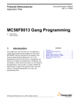
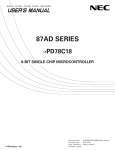
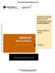
the SC110. Figure 1-1 shows a block diagram of a typical SOC chip made up of the SC110 core and
associated SOC components (described below). Although not indicated in this configuration, a typical
SOC can contain more than one SC110 core.
Freescale Semiconductor, Inc...
In addition, an on-chip instruction set extension accelerator can be used to provide unique application
solutions such as graphics acceleration and video processing, which require specific arithmetic operations
in addition to the main instruction set.
•
Level 1 (L1) Memory Expansion Area — On-chip L1 memories operating at full core frequency
are connected to the DSP core through this area. Memory is unified and can be used for both
program and data storage. Different technologies such as SRAM or ROM can be used to implement
the memory.
•
SC110 DSP core — The processor in which the DSP application code is executed,
and which includes:
— The program sequencer unit (PSEQ)
— A data arithmetic logic unit (DALU)
— An address generation unit (AGU) that contains two address arithmetic units (AAU)
•
Peripheral and Accelerator Expansion Area — This area includes the functional units that
interface between the core and the application, most importantly the functions that send and receive
data from external input/output sources. In addition, this area includes accelerators that execute
portions of the application, in order to boost performance and decrease power consumption. This
area is application-specific and may or may not include various functional units such as:
— Host interface
— Synchronous serial interface
— Serial communication interface
— Viterbi accelerator
— Timers
— Filter coprocessors
•
System Expansion Area — This area includes the functional units that interface between the DSP
core and the application (with the exception of the input/output peripherals and accelerators). This
area is application-specific, and may include various functional units such as:
— External memory interface
— Direct memory access (DMA) controller
— Cache controller for either data or program
— Interrupt control unit
— On-chip Level 2 (L2) memory expansion modules (see note below)
— Other processor cores
Note:
1-4
Level 2 memory expansion does not operate at full core frequency. The maximum operating
frequency of L2 memory depends on the memory technology. For example, embedded FLASH or
DRAM may operate at lower frequency than SRAM.
SC110 DSP Core Reference Manual
For More Information On This Product,
Go to: www.freescale.com
Freescale Semiconductor, Inc. Core Architecture Features
Level-1 Memory Expansion Area
Unified Data and Program Memory
ROM, RAM
System
Expansion Area
SC110 DSP Core
Program Sequencer Unit
External Memory
Interface
True 16-bit Instruction Set
Freescale Semiconductor, Inc...
Variable Length Execution Set (VLES) Model
DMA
Cache
Data Arithmetic
2 Address
Logic Unit
Generation Units
Interrupt Controller
Level-2 Memory
Expansion
Peripheral and Accelerators Expansion Area
Standard Input/Output Peripherals
Application Specific Accelerators
General Purpose Programmable Accelerator
Figure 1-1. Block Diagram of a Typical SOC Configuration with the SC110 Core
1.3.2 Variable Length Execution Set (VLES) Software Model
The VLES software model is the instruction grouping used by the SC110 to address the requirements of
DSP kernels. Using an orthogonal compiler-friendly instruction set, this model maintains a compact code
density for applications.
All SC110 instruction words are 16 bits wide. Most instructions are encoded with one word. Each SC110
instruction encodes an atomic (lowest-level) operation. For example, MAC and store (move) instructions
are encoded in 16 bits. Since atomic operations need fewer bits to encode, the 16-bit instruction set
becomes fully orthogonal and very rich in the functionality it supports.
In order to execute signal processing kernels, a set of SC110 instructions can be grouped to be executed in
parallel. The PSEQ performs this automatically with up to one DALU instruction and two AGU
instructions executed at the same time.
SC110 DSP Core Reference Manual
For More Information On This Product,
Go to: www.freescale.com
1-5
Introduction
Freescale Semiconductor, Inc.
1.4 Software Development Tools
StarCore offers the following set of tools and utilities to assist you in developing code for applications
using the SC110 DSP core:
•
SC100 C Compiler
•
SC100 Assembler
•
SC100 Linker
•
SC100 Utilities
•
SC100 Simulator
Freescale Semiconductor, Inc...
The SC100 tools support the executable and linking format (ELF) for object files. For a description of this
format, refer to the SC100 Application Binary Interface Reference Manual.
1.4.1 SC100 C Compiler
A key feature of the SC100 C Compiler is its ability to convert C source code into highly optimized
assembly code. The compiler supports varying levels of optimization, which can be combined with global
optimization for best results. Global optimization is a complex process that applies the required level of
optimization across all the files in the application at the same time. As a result, the process produces the
most efficient code.
Other features of the SC100 Compiler include the following:
•
Conformance to the ANSI C standard
•
Support of a set of DSP extensions
•
Intrinsic function support for ITU/ETSI primitives: saturating, non-saturating,
and double-precision arithmetic
•
Runtime libraries and environments
•
Easy integration of assembly code into C code
The compiler converts C source code into assembly code, which can then be assembled and linked with
other assembly files and library object modules to form an executable program. The compiler utilizes a
shell, which has been built into the compiler in order to simplify its use, to control the processing of source
files through the preprocessing, compilation, optimization, assembly, and linking stages. At each stage, a
different tool accepts the input files based on their file extensions, processes them, and outputs the
transformed code for processing by the next development tool (see Figure 1-2).
1-6
SC110 DSP Core Reference Manual
For More Information On This Product,
Go to: www.freescale.com
Freescale Semiconductor, Inc.Software Development Tools
C
Source Files
.c, .h
SHELL
C Preprocessor
.i
Freescale Semiconductor, Inc...
C Front End
.obj
Library
IR Files
Configuration
Files
Optimizer
.lib
.sl
Assembler
.asm
.sl
External
Assembly Files
.eln
Library Object
Modules
Linker
.elb
Executable
Program
.eld
Figure 1-2. SC100 Compiler Shell
For a complete description of the SC100 Compiler and its use, refer to the SC100 C Compiler
User’s Manual.
SC110 DSP Core Reference Manual
For More Information On This Product,
Go to: www.freescale.com
1-7
Introduction
Freescale Semiconductor, Inc.
1.4.2 SC100 Assembler
The SC100 Assembler converts handwritten or compiler-generated SC110 assembly code into ELF object
files. Key features of the assembler include the following:
•
Expression evaluation using numeric and string constants, operators, and built-in functions
•
Modular programming using sections
•
Macros that allow variable arguments
•
Conditional assembly
Freescale Semiconductor, Inc...
For a complete description of the SC100 Assembler and its use, refer to the SC100 Assembly Language
Tools User’s Manual.
1.4.3 SC100 Linker
The SC100 Linker combines all relocatable object files and archive files, relocates their data, adjusts the
symbol references, and generates an executable object file. The linker allows you to break up a large
program into more manageable modules that can be assembled separately. This is handy when
troubleshooting an application. Only the module with a problem needs to be edited and reassembled. The
updated object module can then be relinked with the other object modules to produce a new executable
object file.
For a complete description of the linker, refer to the SC100 Assembly Language Tools User’s Manual.
1-8
SC110 DSP Core Reference Manual
For More Information On This Product,
Go to: www.freescale.com
Freescale Semiconductor, Inc.Software Development Tools
1.4.4 SC100 Utilities
Included with the SC100 software development tools are several utilities that process or interpret object
files. These utilities are listed in Table 1-1.
For a description of the SC100 utilities and their use, refer to the SC100 Assembly Language Tools
User’s Manual.
Table 1-1. SC100 Utilities
Freescale Semiconductor, Inc...
Utility
Name
Description
arsc100
Archiver
Groups separate object files together into a single file for linking or
archival storage
sc100-dis
Disassembler
Disassembles executable instructions contained in object files
sc100-elfdump
ELF File Dump
Outputs a formatted display of the contents of object files
sc100-nm
Name
Lists the symbolic information for object files
sc100-size
Size
Lists the size of sections and segments contained in object files
1.4.5 SC100 Simulator
The SC100 Simulator is an interactive simulation tool that provides cycle-accurate measurement of code
execution time. It duplicates the functions of the SC110 DSP core, including memory and register updates
associated with code execution and exception processing activity.
The SC100 Simulator has a command-based interface, which makes it possible to do the following:
•
Load executable object files into the simulator’s memory.
•
Read memory values from an input file or save memory values to an output file.
•
Log simulator sessions.
•
Examine or change the contents of registers and memory.
•
Control the program’s execution by:
— Setting breakpoints and running the program until the break condition is met.
— Stepping through the program for a specified number of instructions or cycles.
Note:
The SC100 Simulator does not include debugging facilities.
More information on the SC100 Simulator is provided in the SC100 Simulator Reference Manual
SC110 DSP Core Reference Manual
For More Information On This Product,
Go to: www.freescale.com
1-9
Freescale Semiconductor, Inc.
Introduction
1.5 StarCore Registry
The StarCore registry (SCR) is a system which identifies the core version. Its use is intended for debugging
software and run-time software. A StarCore Identification number, SCID, is encoded in bits 23-17 of the
EOnCE Status Register (ESR). This 32-bit, memory-mapped, read-only register is located at offset 00
from the EOnCE register base address defined by each System-on-a-Chip (SOC) derivative. The SCID can
be read through the JTAG standard test interface or run-time software using the MOVE instruction. The
SCID binary value can be placed in a data register by reading ESR, shifting right by 17 bits, and ANDing
the result with a $0000 007F mask. Reading ESR using SC100 instructions does not activate the EOnCE
block, thus saving power in actual operation. An example code sequence is:
Freescale Semiconductor, Inc...
move.w ($00800002),d4
;reads from memory location of high portion ESR, assuming
that the EOnCE base address is $0080 0000. Bits 31-16 of
the ESR go to bits 15-0 of D4.
;shifts right 1 bit
;clears high portion
;clears bits 15-7, leaves the SCID in data register d4
lsr d4
and #0,d4.h
and #$007f,d4.l
The SCID has three fields:
•
REVNO (bits 23-21) instruction set version
•
RESERVED (bit 20) undefined
•
CORETP (bits 19-17) core architecture version
The REVNO field generally identifies the basic instruction set revision of the SC100 core. It identifies the
availability of new instructions and corrections to existing instructions. Binary-encoded programs will
generally run without modification on later versions of the instruction set. Changes in REVNO imply a
software tools switch, different software simulator and different host debugger.
The RESERVED field provides space for future expansion. It is currently undefined and should always be
zero for future compatibility.
The CORETP field identifies the architecture member within the SC100 family. It identifies the
availability of new execution units and VLES grouping capabilities. Note that execution units and VLES
can scale up or down without altering the basic instruction set. Changes in CORETP imply a software tools
switch, different software simulator and different host debugger.
The following table lists current assignments of REVNO and CORETP.
Table 1-2. SCID Assignments
Hex
SCID
Bits 23-21
REVNO
Bit 20
Reserved
Bits 19-17
CORETP
Instruction Set
Version
Tools
Cores
Example
SOC
00
000
0
000
Original
beta
SC140 rev 0
Pre-Chip
10
001
0
000
V1
1.0.0
SC140 rev
0_1SC140S V1
MSC8101
11
001
0
001
V1
1.0.0
SC140 rev 0_1
Rainbow
21
010
0
001
V2
1.5.0
SC140 rev
ASC140S V2
MSC8102Sta
rPro
22
010
0
010
V2
1.5.0
SC110S V2
1-10
SC110 DSP Core Reference Manual
For More Information On This Product,
Go to: www.freescale.com
Freescale Semiconductor, Inc.
StarCore Registry
In SC110 and SC140 implementations, the SCID is defined at the SOC level by strapping a set of core
interface signals that define the REVNO and CORETP fields during reset. Therefore, all SOC designs
must conform to the SCID to derive the core identification benefits for host-based software tools and
run-time software. In future cores, StarCore will strap these internally and remove the core interface
signals.
The SCID should not be used for SOC or mask set identification outside the control of StarCore. There was
one entry (SCID=$11) already being used for SOC identification when the StarCore Registry was
transferred to StarCore control. Partner products should add an off-core SOC or mask set identification
register, independent of the SCR. In the future, StarCore will use the SCR only for on-core identification.
Freescale Semiconductor, Inc...
The SCID may assist in migrating applications software and software development tools across StarCores.
Software tools developers and run-time software need to assess the whole SCID (both REVNO,
RESERVED and CORETP fields) to determine possible code migration from core to core. Note that the
SCR does not guarantee identical timing across SCIDs.
For the same CORETP, software written for a lower REVNO will produce the same results on a higher
REVNO except where the higher REVNO introduces a bug fix to an existing instruction. These bug fixes
may present software migration and tools issues.
For the same REVNO, software written for a lower CORETP may not run on a higher CORETP because
CORETP is not a monotonic scalability index. A higher CORETP may have more or less execution units
and VLES grouping capabilities than a lower CORETP. For example, software written for the SC140
(CORETP = 001) will not run and produce the same results on a SC110 (CORETP = 010) having the same
or higher REVNO. Software tools developers and run-time software need to be aware of the actual
CORETP software migration issues.
SC110 DSP Core Reference Manual
For More Information On This Product,
Go to: www.freescale.com
1-11
Freescale Semiconductor, Inc.
Freescale Semiconductor, Inc...
Introduction
1-12
SC110 DSP Core Reference Manual
For More Information On This Product,
Go to: www.freescale.com
Freescale Semiconductor, Inc.
Chapter 2
Core Architecture
Freescale Semiconductor, Inc...
This chapter provides an overview of the SC110 core architecture. It describes the main functional blocks
and data paths of the core.
2.1 Architecture Overview
The SC110 core provides the following main functional units:
•
Data arithmetic and logic unit (DALU)
•
Address generation unit (AGU)
•
Program sequencer unit (PSEQ)
To provide data exchange between the core and the other on-chip blocks, the following buses are
implemented:
•
Two data memory buses (address and data pairs: XABA and XDBA, XABB and XDBB) that are
used for all data transfers between the core and memory.
•
Program data and address buses (PDB and PAB) for carrying program words from the memory to
the core.
•
Special buses to support tightly coupled external user-definable instruction set accelerators.
A block diagram of the SC110 core is shown in Figure 2-1.
SC110 DSP Core Reference Manual
For More Information On This Product,
Go to: www.freescale.com
2-1
Freescale Semiconductor, Inc.
Core Architecture
.
32
32
XDBB
32
XDBA
32
XABB
XABA
64
PAB
PDB
Unified
Data/Program Memory
32
64
Program
Freescale Semiconductor, Inc...
Sequencer
StarCore
SC110
Core
Address G enerator
Register File
DALU
Register
File
EOnCE™
Instruction
Set
Accelerator
Power
Management
AGU
2 AAUs
BM U
DALU
Clock
25
G enerator
Instruction Bus
Figure 2-1. Block Diagram of the SC110 Core
2.1.1 Data Arithmetic Logic Unit (DALU)
The DALU performs arithmetic and logical operations on data operands in the SC110 core. The
components of the DALU are as follows:
•
A register file of sixteen 40-bit registers
•
An ALU containing a multiply-accumulate (MAC) unit and a bit-field unit (BFU)
•
Four data bus shifter/limiters
The MAC unit and BFU can access all the DALU registers. Each register is partitioned into three portions:
two 16-bit registers (low and high portion of the register) and one 8-bit register (extension portion).
Accesses to or from these registers can be in widths of 8 bits, 16 bits, 32 bits, or 40 bits, depending on the
instruction.
The two data buses between the DALU register file and the memory are each 32 bits wide. This enables a
high data transfer speed between memory and registers. The move instructions vary in access width from 8
bits to 32 bits, and can transfer multiple words within the 32-bit constraint. MOVE instructions to and from
the memory interface define the access width.
•
MOVE.B loads or stores bytes (8-bit).
•
MOVE.W or MOVE.F loads or stores integer or fractional words (16-bit).
•
MOVE.2W, MOVE.2F or MOVE.L loads or stores two integers, two fractions and long words
respectively (32-bit).
With the ability to execute any two MOVE instructions in parallel every clock cycle, a maximum data
throughput of 2.4 GBytes/second (at 300 MHz) can be achieved between the memory and the register file.
2-2
SC110 DSP Core Reference Manual
For More Information On This Product,
Go to: www.freescale.com
Freescale Semiconductor, Inc.
Architecture Overview
2.1.1.1 Data Register File
The DALU registers can be read or written over the data buses (XDBA and XDBB). A DALU source
operands for DALU arithmetic instructions always originate from DALU registers. Simultaneous writes to
a destination register are illegal. The destination of every arithmetic operation is a DALU register, and
each such destination can be used as a source operand for the operation immediately following, without
any time penalty.
2.1.1.2 Multiply-Accumulate (MAC) Unit
Freescale Semiconductor, Inc...
The MAC unit comprises the main arithmetic processing unit of the SC110 core and performs the
arithmetic operations. The MAC unit has a 40-bit input and outputs one 40-bit result in the form of
[Extension:High Portion:Low Portion] (EXT:HP:LP).
The multiplier executes 16-bit by 16-bit fractional or integer multiplication between two’s complement
signed, unsigned, or mixed operands (16-bit multiplier and multiplicand). The 32-bit product is
right-justified, sign-extended, and may be added to the 40-bit contents of one of the 16 data registers.
2.1.1.3 Bit-Field Unit (BFU)
The BFU contains a 40-bit parallel bidirectional shifter with a 40-bit input and a 40-bit output, a mask
generation unit, and a logic unit. The BFU is used in the following operations:
•
Multi-bit left/right shift (arithmetic or logical)
•
One-bit rotate (right or left)
•
Bit-field insert and extract
•
Count leading bits (ones or zeros)
•
Logical operations
•
Sign or zero extension operations
2.1.1.4 Shifter/Limiters
Eight shifter/limiters provide scaling and limiting on 32-bit transfers from the data register file to memory.
Scaling up or down by one bit is programmable as is limiting to the maximum values provided in 32 bits.
For more detailed information, see Section 2.2.1.4, “Data Shifter/Limiter,” Section 2.2.1.5, “Scaling,” and
Section 2.2.1.6, “Limiting.”
2.1.2 Address Generation Unit (AGU)
The AGU contains address registers and performs address calculations using integer arithmetic necessary
to address data operands in memory. It implements four types of arithmetic: linear, modulo, multiple
wrap-around modulo, and reverse-carry. The AGU operates in parallel with other core resources to
minimize address generation overhead.
The AGU in the SC110 core has two address arithmetic units (AAU) to allow two address generation
operations at every clock cycle. The AAU has access to:
•
Sixteen 32-bit address registers (R0–R15), of which R8–R15 can also be used as base address
registers for modulo addressing.
•
Four 32-bit offset registers (N0–N3).
SC110 DSP Core Reference Manual
For More Information On This Product,
Go to: www.freescale.com
2-3
Core Architecture
•
Freescale Semiconductor, Inc.
Four 32-bit modulo registers (M0–M3).
The two AAUs are identical. Each contains:
•
A 32-bit full adder, used for offset calculations.
•
A second 32-bit full adder, used for modulo calculations.
Each AAU can update one address register in the address register file in one instruction cycle.
Freescale Semiconductor, Inc...
The AGU also contains a 32-bit modulo control register (MCTL). This control register is used to specify
the addressing mode of the R registers: linear, reverse-carry, modulo, or multiple wrap-around modulo.
When modulo addressing mode is selected, the MCTL register is used to specify which of the four modulo
registers is assigned to a specific R register.
Explicit instructions in the SC110 instruction set are used to execute arithmetic operations on the address
pointers. This capability can also be used for general data arithmetic. In addition, the AGU generates
change-of-flow program addresses and updates the stack pointers as needed.
2.1.2.1 Stack Pointer Registers
Two special registers with special addressing modes are used for software stacks. These are the Normal
mode stack pointer (NSP) and the Exception mode stack pointer (ESP). Both the ESP and the NSP are
32-bit read/write address registers with pre-decrement and post-increment updates. Both are offset with
immediate values to allow random access to a software stack. The ESP is used by stack instructions when
the SC110 is in the Exception mode of operation, which is entered when exceptions occur. The NSP is
used in Normal mode when there are no exceptions. The existence of two stack pointers enables separate
allocation of stack space by the operating system and each application task, which optimizes memory use
in multi-tasking systems.
2.1.2.2 Bit Mask Unit (BMU)
The BMU provides an easy way of setting, clearing, inverting, or testing a selected, but not necessarily
adjacent, group of bits in a register or memory location.
The BMU supports a set of bit mask instructions that operate on:
•
All AGU pointers (R0–R15)
•
All DALU registers (D0–D15)
•
All control registers (EMR, VBA, PCTL0, PCTL1, SR, MCTL)
•
Memory locations
Only a single bit mask instruction is allowed in any single execution set since only one execution unit
exists for these instructions.
A subset of the bit mask instructions (BMTSET) provides hardware support of semaphoring, providing
one instruction for read-modify-write.
2-4
SC110 DSP Core Reference Manual
For More Information On This Product,
Go to: www.freescale.com
Freescale Semiconductor, Inc.
Architecture Overview
2.1.3 Program Sequencer Unit (PSEQ)
The PSEQ performs instruction fetch, instruction dispatch, hardware loop control, and exception
processing. The PSEQ implements three out of the five stages of the pipeline and controls the different
processing states of the SC110 core. The PSEQ consists of three hardware blocks:
•
Program dispatch unit (PDU)—Responsible for detecting the execution set out of a one or two fetch
set, and dispatching the execution set’s various instructions to their appropriate execution units
where they are decoded.
•
Program control unit (PCU)—Responsible for controlling the sequence of the program flow.
•
Program address generator (PAG)—Responsible for generating the program counter (PC) for
instruction fetch operations, including hardware looping.
Freescale Semiconductor, Inc...
The PSEQ implements its functions using the following registers:
•
PC—Program counter register
•
SR—Status register
•
SA0-3—Four start address registers (SA0–SA3)
•
LC0-3—Four loop counter registers (LC0–LC3)
•
EMR—Exception and mode register
•
VBA—Interrupt vector base address register
2.1.4 Enhanced On-Chip Emulator (EOnCE)
The EOnCE module provides a non-intrusive means of interacting with the SC110 core and its peripherals
so that a user can examine registers, memory, or on-chip peripherals as well as define various breakpoints
and read the trace-FIFO. The EOnCE module greatly aids the development of hardware and software on
the SC110 core processor, EOnCE interfacing with the debugging system through on-chip JTAG TAP
controller pins. Refer to Chapter 4, “Emulation and Debug (EOnCE)” for details.
2.1.5 Instruction Set Accelerator Interface
A user-defined instruction set accelerator module provides a means of enhancing the SC110 basic
instruction set with additional instructions. These additional instructions are executed in an external
module connected to the core. The new instructions are added to the SC110 Assembler and Compiler via
intrinsic libraries making application-specific or general-purpose functions available to the user.
A 25-bit instruction bus from the SC110 core to the instruction set accelerator enables the definition and
support of a very rich instruction set. The instruction set accelerator is also connected to the 64-bit data
bus, providing a large data bandwidth to the main memory system.
2.1.6 Memory Interface
The SC110 core uses a unified memory space. Each address can contain either program information or
data. The exact memory configuration is customizable for each chip containing an SC110 core. Memory
space typically consists of on-chip RAM and ROM that can be expanded off-chip. The memory system
must support two parallel data accesses. However, it may issue stalls due to its specific implementation.
Refer to Section 2.4, “Memory Interface,” for further details.
Both internal and external memory configurations are specific to each member of the SC110 family.
SC110 DSP Core Reference Manual
For More Information On This Product,
Go to: www.freescale.com
2-5
Core Architecture
Freescale Semiconductor, Inc.
2.2 DALU
This section describes the architecture and operation of the DALU, the block where most of the arithmetic
and logical operations are performed on data operands. In addition, this section details the arithmetic and
rounding operations performed by the DALU as well as its programming model.
2.2.1 DALU Architecture
Freescale Semiconductor, Inc...
The DALU performs most of the arithmetic and logical operations on data operands in the SC110 core.
The data registers can be read from or written to memory over the XDBA and the XDBB as 8-bit, 16-bit,
or 32-bit operands. The 32-bit wide data buses, XDBA and XDBB, support the transfer of several operands
in a single access. The source operands for the DALU, which may be 16, or 40 bits, originate either from
data registers or from immediate data. The results of all DALU operations are stored in the data registers.
DALU operations are performed in one clock cycle. The destination of every arithmetic operation can be
used as a source operand for the operation immediately following without any time penalty.
The components of the DALU are as follows:
•
A register file of sixteen 40-bit registers
•
An ALU, containing a MAC unit and a BFU with a 40-bit barrel shifter
•
Four data bus shifter/limiters allow scaling and limiting of two 16-bit operands transferred over each
of the XDBA and XDBB buses in a single cycle
Figure 2-2 shows the architecture of the DALU.
Memory Data Bus 1 (XDBA)
Memory Data Bus 2 (XDBB)
32
32
32
32
(8) Shifter/Limiters
40
40
40
40
Data Registers D0–D15
40
40
40
ALU
Figure 2-2. DALU Architecture
2-6
SC110 DSP Core Reference Manual
For More Information On This Product,
Go to: www.freescale.com
Freescale Semiconductor, Inc.
DALU
The DALU programming model is shown in Table 2-1. Register D0 refers to the entire 40-bit register,
whereas D0.e, D0.h, and D0.l refer to the extension: high portion and low portion of the D0 register,
respectively. In addition, one limit tag bit is associated with each data register. L0–L15 are concatenated to
D0–D15, respectively.
Freescale Semiconductor, Inc...
Table 2-1. DALU Programming Model
LIMIT
EXT
HP
LP
L0
D0.e
D0.h
D0.l
L1
D1.e
D1.h
D1.l
L2
D2.e
D2.h
D2.l
L3
D3.e
D3.h
D3.l
L4
D4.e
D4.h
D4.l
L5
D5.e
D5.h
D5.l
L6
D6.e
D6.h
D6.l
L7
D7.e
D7.h
D7.l
L8
D8.e
D8.h
D8.l
L9
D9.e
D9.h
D9.l
L10
D10.e
D10.h
D10.l
L11
D11.e
D11.h
D11.l
L12
D12.e
D12.h
D12.l
L13
D13.e
D13.h
D13.l
L14
D14.e
D14.h
D14.l
L15
D15.e
D15.h
D15.l
SC110 DSP Core Reference Manual
For More Information On This Product,
Go to: www.freescale.com
2-7
Core Architecture
Freescale Semiconductor, Inc.
2.2.1.1 Data Registers (D0–D15)
In this section, the D0–D15 data registers are referred to as Dn. They can be used as:
•
Source operands
•
Destination operands
•
Accumulators
The registers can serve as input buffer registers between XDBA or XDBB and the ALUs. The registers are
used as DALU source operands, allowing new operands to be loaded for the next instruction while the
register contents are used by the current arithmetic instruction.
Freescale Semiconductor, Inc...
Each data register Dn has a limit tag bit (Ln) which is used to signify whether the extension portion of the
register is in use. The limit tag bit Ln is coupled to the extension portion Dn.e, which forms a 9-bit operand
for the purpose of storing these bits to memory. See Section 2.2.1.6, “Limiting,” for further details.
The data registers can be accessed over XDBA and XDBB with three data widths:
•
A long-word access, writing or reading 32-bit operands
•
A word access, writing or reading 16-bit operands
•
A byte access, writing or reading 8-bit operands
For move instructions of fractional data, the transfer of a Dn register to memory over XDBA and XDBB is
protected against overflow by substituting a limiting constant for the data that is being transferred. The
content of Dn is not affected should limiting occur. Only the value transferred over XDBA or XDBB is
limited. This process is commonly referred to as transfer saturation and should not be confused with the
arithmetic saturation mode as described in Section 2.2.2.7, “Arithmetic Saturation Mode.”
Limiting is performed after the contents of the register have been shifted according to the scaling mode.
Shifting and limiting are performed only for MOVES instructions when a fractional operand is specified as
the source for a data move over XDBA or XDBB. When an integer operand is specified as the source for a
data move, shifting and limiting are not performed.
Automatic sign extension (or zero extension of the data values into the 40-bit registers) is provided when
an operand is transferred from memory to a data register. Sign extension can occur when loading the Dn
register from memory. If a fractional word operand is to be written to a data register, the high portion (HP)
of the register is written with the word operand. The low portion (LP) is zero-filled. The EXT portion is
sign-extended from the HP, and the limit tag bit (Ln) is cleared.
When an integer word operand is to be written to a data register, the LP portion of the register is written
with the word operand. The HP and EXT portions are either zero-extended or sign-extended from the LP.
Long-word operands are written into the HP:LP portions of the register. The EXT portion is zero-extended
or sign-extended, and the limit tag bit (Ln) is cleared.
When a byte operand is to be written to a data register, the register’s first 8-bit portion of the LP
(Dn.1[7:0]) is written with the byte operand. The following eight bits of the LP (Dn.1[15:8]), the high
portion, and the EXT are either zero-extended or sign-extended from the LP lower byte. The limit tag bit
(Ln) is cleared.
2-8
SC110 DSP Core Reference Manual
For More Information On This Product,
Go to: www.freescale.com
Freescale Semiconductor, Inc.
DALU
A special case of the MOVE.L instruction is used for reading from or writing to the EXT portion of a data
register. Six variations of this instruction save (restore) the extension bits and Ln bit of data registers to
(from) memory. One of the variations writes to memory the Ln bit and extension bits of an even and an odd
pair of registers. Another variation reads bits 8:0 from memory to the extension bits and the Ln bit of an
even register. Another variation reads bits 24:16 to the extension bits and the Ln bit of an odd register.
Memory writes are done from the even/odd pair of registers. Memory reads are done to a single register.
An extension saved to memory from an even numbered register must be restored to an even register,
likewise for odd registers.
All move instructions are described in detail in Section A, “SC110 DSP Core Instruction Set.” .
Table 2-2 summarizes the various types of data bus write access to the data registers.
Freescale Semiconductor, Inc...
Note:
When an unsigned long operand is written to a data register, Dn.e is zero-extended.
Table 2-2. Write to Data Registers
Operand Type
Ln
Dn.e
Dn.h
Dn.l
Fractional word
Zero-extended
Sign-extended
Operand
Zero-filled
Integer Byte
Zero-extended
Zero-extended/
Sign-extended
Zero-filled/
Sign-extended
Upper byte - Sign-extended/zero-extended
Lower byte - Operand
Integer Word
Zero-extended
Zero-extended/
Sign-extended
Zero-filled/
Sign-extended
Operand
Long
Zero-extended
Zero-extended/
Sign-extended
Operand
Operand
2 Extensions - Long
Operand
Operand
Unchanged
Unchanged
Table 2-3 summarizes the various types of data bus read accesses from the data registers.
Table 2-3. Read from Data Registers
Operand Type
Memory Data Bus.h
Memory Data Bus.l
Limiting/Scaling
Fractional Word
-
Dn.h
Yes/No (See Note)
Fractional Long
Dn.h
Dn.l
Yes/No (See Note)
Integer Word
-
Dn.l
No
Integer Long
Dn.h
Dn.l
No
Integer Byte
-
Low byte - Dn.l[7:0]
No
2 Extensions - Long
EXT word: {7 zero bits, Ln+1,
Dn+1.e}
EXT word: {7 zero bits, Ln,
Dn.e}
No
Note:
A fractional word or fractional long word can be written to memory with or without limiting and
shifting. See MOVE.F and MOVES.F in Section A, “SC110 DSP Core Instruction Set.”
The register file architecture and the 32-bit wide data buses XDBA and XDBB support wide data transfers
between the memory and the data registers. Up to two 16-bit words or one 32-bit long word can be
transferred between the register file and the memory in a single move operation on each data bus, XDBA
or XDBB.
Table 2-4 summarizes the various data widths for data moves from/to the data register file.
SC110 DSP Core Reference Manual
For More Information On This Product,
Go to: www.freescale.com
2-9
Freescale Semiconductor, Inc.
Core Architecture
.
Table 2-4. Data Registers Access Width
Operand Type
Data Width (Bits)
Byte
8
Word
16
Long
32
Two word
32
Freescale Semiconductor, Inc...
2.2.1.2 Multiply-Accumulate (MAC) Unit
The MAC unit is the arithmetic part of the ALU containing both a multiplier and an adder. It also performs
other operations such as rounding, saturation, comparisons, and shifting. Inputs to the MAC unit are from
data registers or from immediate data programmed into the instruction. As many as three operands may be
inputs. The destination for MAC instructions is always a data register in the 40-bit form EXT:HP:LP. The
multiplier executes 16 by 16 parallel multiplication of two’s complement data, signed or unsigned,
fractional or integer. The multiplier output can be accumulated with 40-bit data in a destination register. A
detailed description of each multiplication operation is given in Section 2.2.2.3, “Multiplication.” The
adder executes addition and subtraction of two 40-bit operands. All MAC instructions are executed in one
clock cycle.
Table 2-5 lists the arithmetic instructions that are executed in the MAC unit. A more detailed description of
each instruction is given in Section A, “SC110 DSP Core Instruction Set.”
Table 2-5. MAC Unit Arithmetic Instructions
Instruction
ABS
Absolute value
ADC
Add long with carry
ADD
Add
ADD2
Add two words
ADDNC.W
Add without changing the carry bit in the SR
ADR
Add and round
ASL
Arithmetic shift left by one bit
ASR
Arithmetic shift right by one bit
CLR
Clear
CMPEQ
Compare for equal
CMPGT
Compare for greater than
CMPHI
Compare for higher (unsigned)
DECEQ
Decrement a data register and set T (the true bit) if zero
DECGE
Decrement a data register and set T if greater than or equal to zero
DIV
2-10
Description
Divide iteration
SC110 DSP Core Reference Manual
For More Information On This Product,
Go to: www.freescale.com
Freescale Semiconductor, Inc.
DALU
Table 2-5. MAC Unit Arithmetic Instructions (Continued)
Instruction
DMACSS
Multiply signed by signed and accumulate with data register
right-shifted by word size
DMACSU
Multiply signed by unsigned and accumulate with data register
right-shifted by word size
IADD
Add integers
IMAC
Multiply-accumulate integers
IMACLHUU
Freescale Semiconductor, Inc...
Description
Multiply-accumulate unsigned integers:
first source from low portion, second from high portion
IMACUS
Multiply-accumulate unsigned integer and signed integer
IMPY.W
Multiply integer
IMPYHLUU
Multiply unsigned integer and unsigned integer:
first source from high portion, second from low portion
IMPYSU
Multiply signed integer and unsigned integer
IMPYUU
Multiply unsigned integer and unsigned integer
INC
Increment a data register
INC.F
Increment a data register (as fractional data)
MAC
Multiply-accumulate signed fractions
MACR
Multiply-accumulate signed fractions and round
MACSU
Multiply-accumulate signed fraction and unsigned fraction
MACUS
Multiply-accumulate unsigned fraction and signed fraction
MACUU
Multiply-accumulate unsigned fraction and unsigned fraction
MAX
Transfer maximum signed value
MAX2
Transfer two 16-bit maximum signed values
MAX2VIT
MAXM
Transfer two 16-bit maximum signed values, update Viterbi flags
Transfer maximum magnitude value
MIN
Transfer minimum signed value
MPY
Multiply signed fractions
MPYR
Multiply signed fractions and round
MPYSU
Multiply signed fraction and unsigned fraction
MPYUS
Multiply unsigned fraction and signed fraction
MPYUU
Multiply unsigned fraction and unsigned fraction
NEG
Negate
RND
Round
SAT.F
Saturate fractional value in data register to fit in high portion
SC110 DSP Core Reference Manual
For More Information On This Product,
Go to: www.freescale.com
2-11
Freescale Semiconductor, Inc.
Core Architecture
Table 2-5. MAC Unit Arithmetic Instructions (Continued)
Instruction
SAT.L
Saturate value in data register to fit in 32 bits
SBC
Subtract long with carry
SBR
Subtract and round
SUB
Subtract
SUB2
Subtract two words
SUBL
Shift left and subtract
SUBNC.W
Freescale Semiconductor, Inc...
Description
TFR
Subtract with no carry bit generation
Transfer data register to a data register
TFRF
Transfer data register to a data register if T bit is false
TFRT
Transfer data register to a data register if T bit is true
TSTEQ
Test for equal to zero
TSTGE
Test for greater than or equal to zero
TSTGT
Test for greater than zero
2.2.1.3 Bit-Field Unit (BFU)
The BFU is the logic part of the ALU. It contains a 40-bit parallel bidirectional shifter (with a 40-bit input
and a 40-bit output) mask generation unit and logic unit. The BFU is used in the following operations:
•
Multi-bit left/right shift (arithmetic or logical)
•
One-bit rotate (right or left)
•
Bit-field insert and extract
•
Count leading bits (ones or zeros)
•
Logical operations
•
Sign or zero extension operations
Table 2-6 lists the instructions which are executed in the BFU. A more detailed description of each
instruction is given in Section A, “SC110 DSP Core Instruction Set.”
2-12
SC110 DSP Core Reference Manual
For More Information On This Product,
Go to: www.freescale.com
Freescale Semiconductor, Inc.
DALU
Freescale Semiconductor, Inc...
Table 2-6. BFU Instructions
Instruction
Description
AND
Logical AND
ASLL
Multi-bit arithmetic shift left
ASLW
Word arithmetic shift left (16-bit shift)
ASRR
Multi-bit arithmetic shift right
ASRW
Word arithmetic shift right (16-bit shift)
CLB
Count leading bits (ones or zeros)
EOR
Bit-wise exclusive OR
EXTRACT
Extract signed bit-field
EXTRACTU
INSERT
Extract unsigned bit-field
Insert bit-field
LSLL
Multi-bit logical shift left
LSR
Logical shift right by one bit
LSRR
Multi-bit logical shift right
LSRW
Word logical shift right (16-bit shift)
NOT
One’s complement (inversion)
OR
Bit-wise inclusive OR
ROL
Rotate one bit left through the carry bit
ROR
Rotate one bit right through the carry bit
SXT.B
Sign extend byte
SXT.L
Sign extend long
SXT.W
Sign extend word
ZXT.B
Zero extend byte
ZXT.L
Zero extend long
ZXT.W
Zero extend word
2.2.1.4 Data Shifter/Limiter
The data shifters/limiters provide special post-processing on data written from a Dn register to the XDBA
or XDBB buses. There are four independent shifters/limiters, two for the XDBA bus and two for the
XDBB bus, allowing transfers to memory of up to two words per MOVES instruction with scaling and
limiting. Each consists of a shifter for scaling followed by a limiter. Note that arithmetic saturation from
DALU operations is a different function. Saturation occurs in the DALU before data is written to a
destination register.
SC110 DSP Core Reference Manual
For More Information On This Product,
Go to: www.freescale.com
2-13
Core Architecture
Freescale Semiconductor, Inc.
2.2.1.5 Scaling
The data shifters in the shifter/limiter unit can perform the following data shift operations:
•
Scale up—Shift data one bit to the left
•
Scale down—Shift data one bit to the right
•
No scaling—Pass the data unshifted
Freescale Semiconductor, Inc...
The four shifters permit direct dynamic scaling of fixed-point data without additional program steps. For
example, this permits straightforward block floating-point implementation of Fast Fourier Transforms
(FFTs).
Scaling occurs if programmed in the scaling mode bits S0 and S1 (bits 4 and 5 in the SR). Scaling of
operands only occurs with the MOVES.F, MOVES.2F, and MOVES.L instructions, moving data from a
DALU register (or registers) to memory. The data in the register is not changed, only the data that is
transferred. The scaling mode also affects the Ln bit calculation and the rounding function for a set of
DALU instructions. Scaling is disabled when the arithmetic saturation mode is set. See Section 3.1.1,
“Status Register (SR),” and below for further details. An example of scaling is provided in Table 2-7.
Table 2-7. Scaling Example
Instruction
Memory/
Register
New Value
Comments
move.w #$0030,r0
r0
$0000 0030
R0 initialized for first memory write
moveu.w #$0200,d0.h
d0
$0200 0000
D0 written
bmset #$10,sr.l
sr
$0000 0010
Scale down set in SR
moves.f d0,(r0)+
$0030
$0100
Memory written with scaled down value
move.l #$00e40020
sr
$00e4 0020
Scale up set in SR
moves.f d0,(r0)
$0032
$0400
Memory written with scaled up value
2.2.1.6 Limiting
The limiting capability is enabled only for the MOVES.F, MOVES.2F, and MOVES.L instructions, and
not for any other fractional moves such as MOVE.F. These instructions move data from DALU register(s)
to memory. The limiting operation takes place in two steps: first, calculating the Ln bit when a previous
ALU instruction wrote to a register, and second, transferring the data from that register with a MOVES
instruction. The transferred data is limited if the Ln bit is set.
2.2.1.6.1 Calculating the Ln Bit
The Ln bit can be set by ALU instructions which are capable of using the extension portion of a data
register. The only use of the Ln bit is to set up or prepare for a subsequent MOVES instruction. The Ln bit
is calculated based on the effective extension bits shown in Table 2-8. These are the bits to the left of the
implied decimal point after scaling. If the bits are not all zeros or all ones, the extension is effectively in
use and the Ln bit will be set. The Ln bit is cleared as data is written to a DALU register if the defining bits
below are all zeros or all ones.
2-14
SC110 DSP Core Reference Manual
For More Information On This Product,
Go to: www.freescale.com
Freescale Semiconductor, Inc.
DALU
Freescale Semiconductor, Inc...
Table 2-8. Ln Bit Calculation
S1
S0
Scaling Mode
Bits Defining the Ln bit Calculation
0
0
No Scaling
Bits 39, 38..............32, 31
0
1
Scale Down
Bits 39, 38..............33, 32
1
0
Scale Up
Bits 39, 38..............31, 30
The Ln bit is calculated (and set or cleared) for the following saturable instructions: ABS, ADC, ADR,
ADD, ADDNC, ASL, ASR, CLR, DECGE, DECEQ, DIV, INC, MAC, MACR, MPY, MPYR, NEG,
RND, SBC, SBCR, SUB, SUBL, SUBNC, and TFRx. The Ln bit calculation is not done if arithmetic
saturation mode is set, except for these instructions: ADC, DIV, SBC, TFR, TFRT, and TFTF. For the
latter six, the Ln bit calculation is done, even if arithmetic saturation mode is set. However, no scaling is
considered in the Ln bit calculation if the arithmetic saturation mode is set, even if a scaling mode bit is set.
The Ln bit is always cleared as a result of the execution of one of the following instructions: MAX,
MAXM, MIN, ADD2, SUB2, MAX2, MAX2VIT, DMACsu, DMACss, MACsu, MACuu, MACus,
MPYsu, MPYuu, MPYus, IADD, SAT, all integer multiplication operations, all BFU operations (as listed
in Table 2-6 on page 2-13), and all MOVE instructions except for the specialized MOVE instruction that
restores (pops the stack) the extension and Ln bits from memory. If the result of these instructions is
required to be limited by a following move operation (a TFR Dn), the Dn instruction should be executed
after the original instruction in order to validate the Ln bit before the value is written to memory using a
MOVES.x operation.
2.2.1.6.2 Limiting with the MOVES Instructions
The second stage of limiting occurs with the execution of a MOVES instruction. A limited value is
substituted for the transferred data if the Ln bit of that register was set. The data in the register is not
changed, only the data transferred.
Having two limiters for each bus allows four operands to be limited independently in the same instruction
cycle. The two data limiters per bus can also be combined to form a 32-bit data limiter per bus for long
word operands.
If limiting occurs, the data limiter substitutes a limited data value having maximum magnitude (saturated)
and the same sign as the 40-bit source register content:
•
$7FFF for 16-bit positive numbers
•
$7FFF FFFF for 32-bit positive numbers
•
$8000 for 16-bit negative numbers
•
$8000 0000 for 32-bit negative numbers
This substitution process is sometimes called transfer saturation. The value in the register is not shifted or
limited, and can be reused by subsequent instructions. If the arithmetic saturation mode is set in the SR,
scaling is not considered in the calculation of the Ln bit. An example of limiting is provided in Table 2-9.
SC110 DSP Core Reference Manual
For More Information On This Product,
Go to: www.freescale.com
2-15
Freescale Semiconductor, Inc.
Core Architecture
Table 2-9. Limiting Example
Memory/
Register
New Value
Comments
move.w #$0020,r0
r0
$0000 0030
R0 holds the address for the first move to memory
moveu.w #$7fff,d0.h
d0
$7fff 0000
d0.h set with the most positive 2’s complement number
moveu.w #$7fff,d1.h
d1
$7fff 0000
d1.h set with the most positive 2’s complement number
add d0,d1,d3
d3
$1:00:fffe 0000
move.f d3,(r0)+
$0030
$fffe
No limiting from the move instruction
moves.f d3,(r0)
$0032
$7fff
Limiting occurs with the moves instruction
Freescale Semiconductor, Inc...
Instruction
L3 bit set from overflow
Note that in the unusual case where arithmetic saturation mode is set between a DALU instruction and a
subsequent moves instruction, scaling with the moves instruction is inhibited. However, limiting will occur
if the Ln bit is already set.
2.2.1.7 Scaling and Arithmetic Saturation Mode Interactions
The following table shows the scaling and limiting operations for the four possible cases of scaling/no
scaling with arithmetic saturation mode on/off. Note that the mode of both scaling and arithmetic
saturation selected is not a normal mode of operation for the core. The “Special Six” instructions referred
to in Table 2-10 and Table 2-11 are ADC, DIV, SBC, TFR, TFRT, and TFTF.
Table 2-10. Scaling and Limiting Operations
Ln Bit Calculation
Scaling
Selected
Limiting
with MOVES
instructions
Saturable
DALU
Instructions
Special Six
Instructions
Other DALU
Instructions
(see note below)
Scaling with
MOVES
Instructions
None
Off
Calculated,
no scaling
Calculated,
no scaling
Cleared
Yes
No
Up/down
Off
Calculated,
with scaling
Calculated,
with scaling
Cleared
Yes
Yes
Off
On
Cleared
Calculated,
no scaling
Cleared
Yes
No
Up/down
On
Cleared
Calculated,
no scaling
Cleared
Yes
No
Note:
2-16
Arithmetic
Saturation
Mode
Limiting will occur if the Ln bit is set.
SC110 DSP Core Reference Manual
For More Information On This Product,
Go to: www.freescale.com
Freescale Semiconductor, Inc.
DALU
The following table (Table 2-11) shows the arithmetic saturation and rounding operations for the four
possible cases of scaling, no scaling, and arithmetic saturation mode on/off.
Table 2-11. Arithmetic Saturation and Rounding Operations
Freescale Semiconductor, Inc...
Scaling
Selected
Arithmetic
Saturation
Mode
Arithmetic Saturation
Rounding
Saturable DALU
Instructions
Special Six Instructions
None
Off
None
None
Rounding with no scaling
Up/down
Off
None
None
Rounding with scaling
considered
None
On
Saturation can occur
None
Rounding with no scaling
Up/down
On
Saturation can occur, no
scaling considered
None
Rounding with no scaling
2.2.2 DALU Arithmetic and Rounding
The following paragraphs describe the DALU data representation, rounding modes, and arithmetic
methods.
2.2.2.1 Data Representation
The SC110 core uses either a fractional or integer two’s complement data representation for all DALU
operations. The main difference between fractional and integer representations is the location of the
decimal (or binary) point. For fractional arithmetic, the decimal (or binary) point is always located
immediately to the right of the most significant bit of the high portion. For integer values, it is always
located immediately to the right of the least significant bit (LSB) of the value. Figure 2-3 shows the
location of the decimal (or binary) point bit weighting and operand alignment for different fractional and
integer representations supported on the SC110 architecture.
SC110 DSP Core Reference Manual
For More Information On This Product,
Go to: www.freescale.com
2-17
Core Architecture
Freescale Semiconductor, Inc.
0
16-bit word operand
D0.h—D15.h,
16-bit memory
40-bit registers
D0—D15
–2
–2
8
20
2–15
2–15 2–16
2–31
Signed Fractional Two’s Complement Representations
Freescale Semiconductor, Inc...
16-bit word operand
D0.l—D15.l,
16-bit memory
40-bit registers
D0—D15
15
–2
214
20
.
–2
39
231
216 215
20
.
Signed Integer Two’s Complement Representations
Figure 2-3. DALU Data Representations
2.2.2.2 Data Formats
Three types of two’s complement data formats are supported by the SC110 core:
•
Signed fractional (SF)
•
Signed integer (SI)
•
Unsigned integer (UI)
The ranges for each of these formats, described below, apply to all data stored in memory as well as data
stored in the data registers. The extension associated with each register allows word growth so that the
most positive fractional number that can be represented in a register is almost 256.0 with the most negative
fractional number being exactly -256.0. When the register extension is in use, the data contained in the
register cannot be stored exactly in memory or in other registers in a single move. In these cases, the
storage error can be minimized by limiting the data to the most positive or most negative number
consistent with the size of the destination, the sign of the register and the MSB of the extension.
2.2.2.2.1 Signed Fractional
In this format, without extension bits 39-32, the N-bit operand is represented using the 1.[N-1] bit format
(1 sign bit, N-1 fractional bits). Signed fractional numbers lie in the following range:
-1.0 ≤ SF ≤+1.0 - 2-[N-1]
For words and long-word signed fractions, the most negative number that can be represented is exactly
–1.0, of which the internal representation is $8000 and $8000 0000, respectively. The most positive word
is $7FFF or 1.0–2-15, and the most positive long word is $7FFF FFFF or 1.0–2-31.
If the extension bits are in use, the most positive number is 256 – 2–31 represented by $7F FFFF FFFF, and
the most negative number is –256, represented by $80 0000 0000.
2-18
SC110 DSP Core Reference Manual
For More Information On This Product,
Go to: www.freescale.com
Freescale Semiconductor, Inc.
DALU
2.2.2.2.2 Signed Integer
This format is used when processing data as integers. Using this format, the N-bit operand is represented
using the N.0 bit format (N integer bits). Signed integer numbers lie in the following range:
-2[N-1] ≤ SI ≤ [2[N-1]-1]
For words and long-word signed integers, the most negative word that can be represented is -32768
($8000) and the most negative long word is -2147483648 ($8000 0000). The most positive word is 32767
($7FFF) and the most positive long word is 2147483647 ($7FFF FFFF).
If the extension bits are in use, N becomes 40, and the most positive number is 239 – 1 represented by
$7F FFFF FFFF. The most negative number is –239, represented by $80 0000 0000.
Freescale Semiconductor, Inc...
2.2.2.2.3 Unsigned Integer
Unsigned integer numbers may be thought of as positive only. The unsigned numbers have nearly twice
the magnitude of a signed number of the same length. Unsigned integer numbers lie in the following range:
0 ≤ UI ≤ [2N-1]
The binary word is interpreted as having a binary point immediately to the right of the LSB. The most
positive word is 65535 ($FFFF). The most positive long word is 232-1 ($FFFF FFFF). The smallest
unsigned number is zero ($0000).
If the extension bits are in use, the range is from zero to +240 – 1.
Table 2-12. Two’s Complement Word Representations
Signed Fractional
Signed Integer
Unsigned Integer
$7FFF
1.0 – 2 –15
$7FFF
2 15 – 1
$FFFF
2 16 – 1
l
l
l
l
$FFFE
2 16 – 2
l
l
l
l
l
l
$0001
2 –15
$0001
+1
l
l
$0000
0
$0000
0
l
l
$FFFF
– 2 –15
$FFFF
–1
l
l
l
l
l
l
l
l
l
l
l
l
$0001
1
$8000
– 1.0
$8000
– 2 15
$0000
0
SC110 DSP Core Reference Manual
For More Information On This Product,
Go to: www.freescale.com
2-19
Freescale Semiconductor, Inc.
Core Architecture
2.2.2.3 Multiplication
Most of the operations are performed identically in fractional and integer arithmetic. However, the
multiplication operation is not the same for integer and fractional arithmetic. As illustrated in Figure 2-4,
fractional and integer multiplication differ by a 1-bit shift. Any binary multiplication of two N-bit signed
numbers gives a signed result that is 2N-1 bits in length. This 2N-1 bit result must then be correctly placed
into a field of 2N-bits to correctly fit into the on-chip registers. For correct fractional multiplication, an
extra 0-bit is placed at the LSB to give a 2N-bit result. For correct integer multiplication, an extra sign bit
is placed at the MSB to give a 2N-bit result.
Signed Multiplication: N x N --> 2N – 1 Bits
Freescale Semiconductor, Inc...
Integer
S
Fractional
S
S
S
X
X
Signed Multiplier
S
S
HP
LP
2N – 1 product
Signed Multiplier
S
HP
LP
0
2N – 1 product
sign extension
zero fill
2N bits
2N bits
Figure 2-4. Fractional and Integer Multiplication
The MPY, MAC, MPYR, and MACR instructions perform fractional multiplication and fractional
multiply-accumulation. The IMPY and the IMAC instructions perform integer multiplication.
2.2.2.4 Division
Fractional division of both positive and signed values is supported using the DIV instruction. The dividend
(numerator) is a 32-bit fraction and the divisor (denominator) is a 16-bit fraction. For a detailed description
of the DIV instruction, see Appendix , “DIV Divide Iteration (DALU) DIV.”
2.2.2.5 Unsigned Arithmetic
Unsigned arithmetic can be performed on the SC110 core architecture. Most of the unsigned arithmetic
instructions are performed the same as the signed instructions. However, some operations require special
hardware and are implemented as separate instructions.
2.2.2.5.1 Unsigned Multiplication
Unsigned multiplication (MPYUU, MACUU) and mixed unsigned-signed multiplication (MPYSU,
MACSU) are used to support double precision, as described in Section 2.2.2.8, “Multi-Precision
Arithmetic Support.” These instructions can be used for unsigned arithmetic multiplication.
2-20
SC110 DSP Core Reference Manual
For More Information On This Product,
Go to: www.freescale.com
Freescale Semiconductor, Inc.
DALU
2.2.2.5.2 Unsigned Comparison
When performing an unsigned comparison, the condition code computation is different from signed
comparisons. The most significant bit of the unsigned operand has a positive weight, while in signed
representation it has a negative weight. Special instructions are implemented to support unsigned
comparison such as CMPHI (compare greater).
Freescale Semiconductor, Inc...
2.2.2.6 Rounding Modes
The SC110 DALU performs rounding of the full register to single precision if requested in the instruction.
The high portion of the register is rounded according to the contents of the low portion of the register.
Then the low portion is cleared. The boundary between the low portion and the high portion is determined
by the scaling mode bits (S0 and S1) in the SR. Two types of rounding are implemented, convergent
rounding and two’s complement rounding. The type of rounding is selected by the rounding mode (RM)
bit in the SR.
Table 2-13 shows the boundary between the high portion and the low portion depending on scaling. The
scaling adjustment is disabled if arithmetic saturation mode is selected.
Table 2-13. Rounding Position in Relation to Scaling Mode
S1
S0
Scaling Mode
High Portion
Low Portion
0
0
No Scaling
39–16
15–0
0
1
Scale Down
39–17
16–0
1
0
Scale Up
39–15
14–0
2.2.2.6.1 Convergent Rounding
Convergent rounding (also called round-to-nearest even number) is the default rounding mod. It is selected
when the rounding mode (RM) bit in the SR is cleared. The traditional rounding method rounds up any
value greater than one-half, and rounds down any value less than one-half. However, the question arises as
to which way one-half should be rounded. If it is always rounded one way, the results are eventually biased
in that direction. Convergent rounding, however, removes the bias by rounding down if the high portion is
even (LSB = 0) and rounding up if the high portion is odd (LSB = 1).
For no scaling, the higher portion (HP) of the register is bits 39:16; the low portion (LP) is bits 15:0. The
HP is incremented by one bit if the LP was > 1/2, or if the LP = 1/2 and bit 16 was 1 (odd). The HP is left
alone if the LP was <1/2, or if LP = 1/2 and bit 16 was 0 (even). After rounding, the LP is cleared. If
scaling down is selected, the HP is bits 39:17 and the LP is bits 16:0. If scaling up is selected, the HP is bits
39:15 and the LP is bits 14:0.
SC110 DSP Core Reference Manual
For More Information On This Product,
Go to: www.freescale.com
2-21
Freescale Semiconductor, Inc.
Core Architecture
Figure 2-5 shows the four cases for rounding a number in the Dn.h register. If scaling is set in the SR, the
rounding position is updated to reflect the alignment of the result when it is put on the data bus. However,
the contents of the register are not scaled.
Case I: If D0.l < $8000 (1/2), then round down (add nothing)
Before Rounding
After Rounding
0
D0.e
D0.h
D0.l
Freescale Semiconductor, Inc...
XX..XX XXX...XXX0100 011XXX....XXX
39
32 31
16 15
0
D0.e
D0.h
D0.l*
XX..XX XXX...XXX0100 000.........000
39
32 31
16 15
0
Case II: If D0.l > $8000 (1/2), then round up (add 1 to D0.h)
Before Rounding
After Rounding
1
D0.e
D0.h
D0.l
XX..XX XXX...XXX0100 1110XX....XXX
39
32 31
16 15
0
D0.e
D0.h
D0.l*
XX..XX XXX...XXX0101 000.........000
39
32 31
16 15
0
Case III: If D0.l = $8000 (1/2), and the LSB of D0.h= 0, then round down (add nothing)
Before Rounding
After Rounding
0
D0.e
D0.h
D0.l
XX..XX XXX...XXX0100 1000........000
39
32 31
16 15
0
D0.e
D0.h
D0.l*
XX..XX XXX...XXX0100 000.........000
39
32 31
16 15
0
Case IV: If D0.l = $8000 (1/2), and the LSB of Do.h = 1, then round up (add 1 to D0.h)
After Rounding
Before Rounding
1
D0.e
D0.h
D0.l
XX..XX XXX...XXX0101 1000........000
39
32 31
16 15
0
D0.e
D0.h
D0.l*
XX..XX XXX...XXX0110 000.........000
39
32 31
16 15
0
*D0.l is always clear, performed during RND, MPYR, and MACR.
Figure 2-5. Convergent Rounding (No Scaling)
2-22
SC110 DSP Core Reference Manual
For More Information On This Product,
Go to: www.freescale.com
Freescale Semiconductor, Inc.
DALU
2.2.2.6.2 Two’s Complement Rounding
When two’s complement rounding is selected by setting the rounding mode (RM) bit in the SR, all values
greater than or equal to one-half are rounded up, and all values less than one-half are rounded down.
Therefore, a small positive bias is introduced.
Freescale Semiconductor, Inc...
For no scaling, the higher portion (HP) of the register is bits 39:16; the low portion (LP) is bits 15:0. The
HP is incremented by one bit if the LP was ≥ 1/2. The HP is left alone if the LP was <1/2. After rounding,
the LP is cleared. If scaling down is selected, the HP is bits 39:17 and the LP is bits 16:0. If scaling up is
selected, the HP is bits 39:15 and LP is bits 14:0.
SC110 DSP Core Reference Manual
For More Information On This Product,
Go to: www.freescale.com
2-23
Freescale Semiconductor, Inc.
Core Architecture
Figure 2-6 shows the four cases for rounding a number in the Dn.h register. If scaling is set in the SR, the
rounding position is updated to reflect the alignment of the result when it is transferred to the data bus.
However, the contents of the register are not scaled.
Case I: If D0.l < $8000 (1/2), then round down (add nothing)
Before Rounding
After Rounding
0
D0.e
D0.h
D0.l
Freescale Semiconductor, Inc...
XX..XX XXX...XXX0100 011XXX....XXX
39
32 31
16 15
0
D0.e
D0.h
D0.l*
XX..XX XXX...XXX0100 000.........000
39
32 31
16 15
0
Case II: If D0.l > $8000 (1/2), then round up (add 1 to D0.h)
Before Rounding
After Rounding
1
D0.e
D0.h
D0.l
XX..XX XXX...XXX0100 1110XX....XXX
39
32 31
16 15
0
D0.e
D0.h
D0.l*
XX..XX XXX...XXX0101 000.........000
39
32 31
16 15
0
Case III: If D0.l = $8000 (1/2), and the LSB of D0.h = 0, then round up (add 1 to D0.h)
Before Rounding
After Rounding
1
D0.e
D0.h
D0.l
XX..XX XXX...XXX0100 1000........000
39
32 31
16 15
0
D0.e
D0.h
D0.l*
XX..XX XXX...XXX0101 000.........000
39
32 31
16 15
0
Case IV: If D0.l = $8000 (1/2), and the LSB of D0.h = 1, then round up (add 1 to D0.h)
Before Rounding
After Rounding
1
D0.e
D0.h
D0.l
XX..XX XXX...XXX0101 1000........000
39
32 31
16 15
0
D0.e
D0.h
D0.l*
XX..XX XXX...XXX0110 000.........000
39
32 31
16 15
0
*D0.l is always cleared, performed during RND, MPYR, and MACR.
Figure 2-6. Two’s Complement Rounding (No Scaling)
2-24
SC110 DSP Core Reference Manual
For More Information On This Product,
Go to: www.freescale.com
Freescale Semiconductor, Inc.
DALU
2.2.2.7 Arithmetic Saturation Mode
By setting the arithmetic saturation mode (SM) bit in the SR, the arithmetic unit’s result is limited to 32
bits (high portion and low portion). The dynamic range of the DALU is therefore reduced to 32 bits. The
purpose of this bit is to provide a saturation mode for algorithms that do not recognize or cannot take
advantage of the extension bits.
Arithmetic saturation operates by checking whether bits 39–31 of a relevant DALU instruction result in all
ones or all zeros. If they are not, and if bit 39 is one, the result receives the negative saturation constant
$FF 8000 0000. If bit 39 is zero, the result receives the positive saturation constant $00 7FFF FFFF. If
saturation occurs, the DOVF bit in the EMR register is set.
Freescale Semiconductor, Inc...
The calculation for saturation is not affected by the scaling mode. In the same way, the rounding of the
saturation constant during execution of MPYR, MACR and RND instructions is independent of the scaling
mode: $00 7FFF FFFF is rounded to $00 7FFF 0000 and $FF 8000 0000 is unchanged.
The instructions that are affected by arithmetic saturation mode are: MAC, MPY, MACR, MPYR, SUB,
ADD, NEG, ABS, RND, DECGE, DECEQ, INC, ADR, SBR, SUBL, ASR, SUBNC, ADDNC, and ASL.
When the arithmetic saturation mode is set, for most of the instructions, the scaling mode bits are ignored
for the calculation of the Ln bit, and the Ln bit cannot be set. For instructions ADC, DIV, SBC, TFR,
TFRT, and TFRF, however, the arithmetic saturation mode is ignored, and the Ln bit will be calculated.
These six are dependent on arithmetic saturation mode to the extent that scaling is not considered in the Ln
bit calculation if arithmetic saturation mode is on. See Section 2.2.1.7, “Scaling and Arithmetic Saturation
Mode Interactions,” on page 2-16 for more information.
The arithmetic saturation mode is always disabled during the execution of the following instructions:
TFR, TFRT, TFRF, MAX, MAXM, MIN, ADD2, SUB2, DIV, SBC, ADC, MAX2, MAX2VIT,
DMACSU, DMACSS, MACSU, MACUS, MACUU, MPYSU, MPYUU, MPYUS, IADD, CMPHI, all
integer multiplication operations, and all BFU operations as described in Table 2-6 on page 2-13. If the
result of these instructions should be saturated, a SAT.L Dn instruction must be executed following the
original instruction.
If the arithmetic saturation mode is set and data saturation occurs, the sticky data overflow bit (DOVF) in
the EMR is set to signify that the arithmetic result before saturation cannot be represented in 32 bits. Note
that if arithmetic saturation mode is not set, the DOVF bit is set when overflow from 40 bits occurs.
Table 2-14 provides an example of the arithmetic saturation mode.
Table 2-14. Arithmetic Saturation Example
Memory/
Register
New Value
Comments
bmset #$0004,sr.l
sr
$00e4 0004
Arithmetic saturation mode set
moveu.w #$7fff,d0.h
d0
$7fff 0000
d0.h set with the most positive 2’s complement number
moveu.w #$7fff,d1.h
d1
$7fff 0000
d1.h set with the most positive 2’s complement number
add d0,d1,d3
d3
$0:00:7fff ffff
Max positive constant loaded in D3. L3 bit not set from
overflow
emr
$0000 0004
DALU overflow bit set
Instruction
SC110 DSP Core Reference Manual
For More Information On This Product,
Go to: www.freescale.com
2-25
Core Architecture
Freescale Semiconductor, Inc.
2.2.2.8 Multi-Precision Arithmetic Support
The SC110 DALU supports multi-precision arithmetic for fractional and integer operations.
2.2.2.8.1 Fractional Multi-Precision Arithmetic
A set of DALU instructions is provided for fractional multi-precision multiplications. When these
instructions are used, the multiplier accepts some combinations of two’s complement signed and unsigned
formats. Table 2-15 lists these instructions.
Freescale Semiconductor, Inc...
Table 2-15. Fractional Signed and Unsigned Two’s Complement Multiplication
Instruction
Description
MPYSU/MACSU
Fractional multiplication and multiply-accumulate with signed × unsigned operands
MPYUS/MACUS
Fractional multiplication and multiply-accumulate with unsigned × signed operands
MPYUU/MACUU
Fractional multiplication and multiply-accumulate with unsigned × unsigned operands
DMACSS
Fractional multiplication with signed × signed operands and 16-bit arithmetic right shift
of the accumulator before accumulation
DMACSU
Fractional multiplication with signed × unsigned operands and 16-bit arithmetic right
shift of the accumulator before accumulation
Figure 2-7 shows how the DMAC instruction is implemented.
16-bit Operand
>> 16
Register Shifter
16-bit Operand
M ultiply
+
40-bit Accum ulate
Figure 2-7. DMAC Implementation
2-26
SC110 DSP Core Reference Manual
For More Information On This Product,
Go to: www.freescale.com
Freescale Semiconductor, Inc.
DALU
Figure 2-8 illustrates the use of these instructions in the case of a double-precision multiplication of
32-bit x 32-bit operands. The “Unsigned x Unsigned” operation is used to multiply or multiply-accumulate
the unsigned low portion of one double-precision number with the unsigned low portion of the other
double-precision number. The “Signed x Unsigned” and “Unsigned x Signed” operations are used to
multiply or multiply-accumulate the signed high portion of one double-precision number with the unsigned
low portion of the other double-precision number. The “Signed x Signed” operation is used to multiply or
multiply-accumulate the two signed high portions of two signed double-precision numbers. The TFRx
instructions in parentheses are optional instructions that are used only in case all 64 bits of the result are
needed. Otherwise, the result is truncated to a 32-bit fraction.
32 bits
D0.h
D0.l
Freescale Semiconductor, Inc...
×
D1.h
D1.l
=
Unsigned × Unsigned
mpyuu
(tfr
D0,D1,D2
D2,D3)
dmacsu
D0,D1,D2
D1.l × D0.l
Signed × Unsigned
+
D0.h × D1.l
+
Unsigned × Signed
macus
(tfr
D0,D1,D2
D2,D4)
D1.h × D0.l
+
Signed × Signed
dmacss
D1.h × D0.h
D0,D1,D2
S Ext
D2.e
D2.h
D2.l
D4.l
D3.l
64 bits
Figure 2-8. Fractional Double-Precision Multiplication
SC110 DSP Core Reference Manual
For More Information On This Product,
Go to: www.freescale.com
2-27
Freescale Semiconductor, Inc.
Core Architecture
Figure 2-9 illustrates the use of the fractional multiplication and multiply-accumulate instructions in the
case of a mixed double-precision multiplication of 16-bit by 32-bit signed operands. The “Signed x
Unsigned” operation is used to multiply the signed high portion of one single-precision number with the
unsigned low portion of the other double-precision number. The “Signed x Signed” DMAC operation is
used to multiply-accumulate the two signed high portions of the two signed operands. The TFRx
instruction in parentheses is an optional instruction that is used only in case all 48 bits of the result are
needed. Otherwise, the result is truncated to a 32 bit fraction.
D0.h
×
D1.h
D1.l
Freescale Semiconductor, Inc...
=
Signed × Unsigned
mpysu
(tfr
dmacss
D0.h × D1.l
D0,D1,D2
D2,D3)
Signed × Signed
+
D1.h × D0.h
D0,D1,D2
S Ext
D2.e
D2.h
D2.l
D3.l
48 bits
Figure 2-9. Fractional Mixed-Precision Multiplication
2.2.2.8.2 Integer Multi-Precision Arithmetic
A set of DALU operations is provided for integer multi-precision multiplications. When these instructions
are used, the multiplier accepts some combinations of two’s complement signed and unsigned formats.
Both signed and unsigned multi-precision multiplication are supported. Table 2-16 lists these instructions.
Table 2-16. Integer Signed and Unsigned Two’s Complement Multiplication
Instruction
Description
IMPYSU/IMACSU
Integer multiplication and multiply-accumulate with signed x unsigned operands
IMPYUU
Integer multiplication with unsigned x unsigned operands
IMPYHLUU
Integer multiply unsigned x unsigned:
first source from high portion, second from low portion
IMACLHUU
Integer multiply-accumulate unsigned x unsigned:
first source from low portion, second from high portion
2-28
SC110 DSP Core Reference Manual
For More Information On This Product,
Go to: www.freescale.com
Freescale Semiconductor, Inc.
DALU
Figure 2-10 illustrates the use of these instructions in the case of a signed integer double-precision
multiplication of 32-bit by 32-bit signed operands. In this example, only a 32-bit result is generated. The
most significant 32 bits are shifted out.The “Unsigned x Unsigned” operation is used to multiply or
multiply-accumulate the unsigned low portion of one double-precision number with the unsigned low
portion of the other double-precision number. The “Signed x Unsigned” and “Unsigned x Signed”
operations are used to multiply or multiply-accumulate the signed high portion of one double-precision
number with the unsigned low portion of the other double-precision number. This example generates only
a 32-bit integer.
32 bits
D0.h
D0.l
×
Freescale Semiconductor, Inc...
D1.h
D1.l
=
Unsigned × Unsigned
impyuu
D1.l × D0.l
D0,D1,D2
Signed × Unsigned
impysu
D0.h × D1.l
D0,D1,D3
+
Unsigned × Signed
imacus
D1.h × D0.l
D0,D1,D3
+
0
D3.l
aslw
D3
add
D2,D3
D3.h
D3.l
32 bits
AA0551
Figure 2-10. Signed Integer Double-Precision Multiplication
SC110 DSP Core Reference Manual
For More Information On This Product,
Go to: www.freescale.com
2-29
Freescale Semiconductor, Inc.
Core Architecture
Figure 2-11 illustrates the use of these instructions in the case of an unsigned integer double-precision
multiplication of 32-bit by 32-bit unsigned operands. In this example, only a 32-bit result is generated. The
most significant 32-bits are shifted out. All multiplications are of the “Unsigned x Unsigned” type using
different combinations of high and low portions.
D0.l
D0.h
×
D1.h
D1.l
=
Unsigned × Unsigned
impyuu d0,d1,d2
D1.l × D0.l
Freescale Semiconductor, Inc...
Unsigned × Unsigned
impyhluu d0,d1,d3
D0.h × D1.l
imaclhuu d0,d1,d3
D1.h × D0.l
+
+
aslw d3
0
D3.l
add d2,d3
D3.h
D3.l
32 bits
Figure 2-11. Unsigned Integer Double-Precision Multiplication
2.2.2.9 Viterbi Decoding Support
A set of DALU and AGU operations is provided for Viterbi decoding kernels. A special MAX2VIT
operation is defined. This instruction functions as a regular MAX2 instruction and is used to transfer two
16-bit maximum signed values. In addition, the MAX2VIT instruction updates two Viterbi flags (VFs)
which reside in the status register as described in Section 3.1.1, “Status Register (SR),” on page 3-1.
Complementary AGU move operations are provided (VSL instructions).
2-30
SC110 DSP Core Reference Manual
For More Information On This Product,
Go to: www.freescale.com
Freescale Semiconductor, Inc.
Address Generation Unit
2.3 Address Generation Unit
The AGU is one of the execution units in the SC110 core. The AGU performs effective address
calculations using the integer arithmetic necessary to address data operands in memory. It also contains the
registers used to generate the addresses. The AGU implements four types of arithmetic: linear, modulo,
multiple wrap-around modulo, and reverse-carry. It operates in parallel with other chip resources to
minimize address generation overhead. The AGU also generates change-of-flow program addresses as
well as updates the stack pointer (SP), whenever needed.
2.3.1 AGU Architecture
Freescale Semiconductor, Inc...
The major components of the AGU are listed below:
•
Eight low bank address registers (R0–R7)
•
Eight high bank address registers (R8–R15), or alternatively, eight base address registers (B0–B7)
•
Two stack pointers (NSP, ESP), only one of which is active at a time (SP)
•
Four offset registers (N0–N3)
•
Four modifier registers (M0–M3)
•
A modifier control register (MCTL)
•
Two address arithmetic units (AAU)
•
One bit mask unit (BMU)
In this section, the registers are referred to as:
•
Rn for any of the R0–R15 address registers
•
Bn for any of the B0–B7 base address registers
•
Ni for any of the N0–N3 offset registers
•
Mj for any of the M0–M3 modifier registers
All the Rn, Bn, SP, Ni, and Mj registers are referred to as AGU registers. All of the AGU registers are
32-bits.
Figure 2-12 shows a block diagram of the AGU.
SC110 DSP Core Reference Manual
For More Information On This Product,
Go to: www.freescale.com
2-31
Freescale Semiconductor, Inc...
Core Architecture
Freescale Semiconductor, Inc.
R8/B0
M0
N0
R9/B1
M1
N1
R10/B2
M2
N2
R11/B3
M3
N3
R12/B4
R13/B5
XABA
XABB
32
32
PAB
32
R0
Address
Arithmetic
Unit
R1
R2
R3
R4
MCTL
R5
R14/B6
R6
R15/B7
R7
NSP
ESP
Bit
Mask
Unit
(BMU)
P ro gram C o unter (P C ) A ddre ss
Memory Data Bus 1 (XDBA)
32
Memory Data Bus 2 (XDBB)
32
Figure 2-12. AGU Block Diagram
All sixteen address registers (R0–R15) as well as the NSP or ESP are used for generating addresses in the
register indirect addressing modes. All four offset registers (N0–N3) can be used by all sixteen address
registers. The four modifier registers (M0–M3) can only be used by the low bank of eight address registers
(R0–R7).
The base address (Bn) registers are uniquely associated with the low bank of Rn registers such that B0 is
used with R0, B1 with R1, and so on.
The BMU is used to perform bit mask operations such as setting, clearing, changing, or testing bits in a
destination according to an immediate mask operand. Data is loaded into the BMU over the data memory
buses XDBA or XDBB. The result is written back over XDBA or XDBB to the destinations in the next
cycle. All bit mask instructions are typically executed in two cycles and work on 16-bit data. This data can
be a memory location or a portion (high or low) of a register. For more information, see Section 2.3.6, “Bit
Mask Instructions.”
2-32
SC110 DSP Core Reference Manual
For More Information On This Product,
Go to: www.freescale.com
Freescale Semiconductor, Inc.
Address Generation Unit
During every instruction cycle, the two AAUs can generate one 32-bit program memory address on the
PAB (in case of change of flow) or two 32-bit data memory addresses (one on each of the XABA and
XABB). Each AAU can generate an address to access a byte, a 16-bit word, or a 32-bit long word operand
in memory to feed into the DALU in a single cycle.
Each AAU can update one address register during one instruction cycle. The modifier control register
(MCTL) specifies the type of arithmetic to be used in the address register update calculation. The address
arithmetic instructions provide arithmetic operations for address calculations or for general purpose
calculations.
Freescale Semiconductor, Inc...
The two AAUs are identical. Each contains a 32-bit full adder, called an offset adder, which can perform
the following:
•
Add or subtract two AGU registers
•
Add an immediate value
•
Increment or decrement an AGU register
•
Add the PC
•
Add with reverse-carry
The offset adder can also perform compare or test operations as well as arithmetic and logical shifts. The
offset values added in this adder can be pre-shifted left by 0, 1, or 2 bits according to the access width. In
reverse-carry mode, the carry propagates in the opposite direction.
A second full adder, called a modulo adder, adds the summed result of the first full adder to a modulo
value, M or minus M, where M is stored in the selected modifier register. In modulo mode, a modulo
comparator tests whether the result is inside the buffer by comparing the results to the B register, choosing
the correct result from the offset adder or the modulo adder.
For more information, see Section 2.3.5, “Arithmetic Instructions on Address Registers.”
SC110 DSP Core Reference Manual
For More Information On This Product,
Go to: www.freescale.com
2-33
Freescale Semiconductor, Inc.
Core Architecture
2.3.2 AGU Programming Model
The programming model of the AGU is shown in Figure 2-13.
The address registers can be programmed for linear addressing, modulo addressing (regular or multiple
wrap-around), and reverse-carry addressing. Automatic updating of address registers is available when
using address register indirect addressing.
Freescale Semiconductor, Inc...
31
0
31
0
R0
N0
R1
N1
R2
N2
R3
N3
R4
31
0
R5
M0
R6
M1
R7
M2
SP (NSP, ESP)
M3
ADDRESS REGISTERS
MCTL
31
0
OFFSET, MODIFIER, and MCTL REGISTERS
R8 / B0
R9 / B1
R10 / B2
R11 / B3
R12 / B4
R13 / B5
R14 / B6
R15 / B7
ADDRESS REGISTERS / BASE ADDRESS REGISTERS
Figure 2-13. AGU Programming Model
2-34
SC110 DSP Core Reference Manual
For More Information On This Product,
Go to: www.freescale.com
Freescale Semiconductor, Inc.
Address Generation Unit
2.3.2.1 Address Registers (R0–R15)
The sixteen 32-bit address registers R0–R15 can contain addresses or general-purpose data. These are
32-bit read/write registers. The 32-bit address in a selected address register is used in calculating the
effective address of an operand. The contents of an address register can point directly to data, or can be
used as an index.
Freescale Semiconductor, Inc...
The sixteen address registers R0–R15 are composed of two separate banks, a low bank (R0–R7) and a high
bank (R8–R15). The high bank can be used alternatively as a base address register bank (B0–B7). Each
address register Rn of the high bank can serve as an address register on condition that the corresponding
Bn-8 register is not used. Both Rn and Bn-8 are mapped to the same physical register. For example, R8 is
available only if R0 is not being used in modulo addressing since this requires the base address register B0.
See Section 2.3.2.6, “Modifier Control Register (MCTL),” for further information. The high bank of
registers can only be used as pointers in the linear mode of addressing since the other modes of addressing
are only encoded for the low bank in the MCTL register.
In addition, an address register can be post-updated according to the addressing mode selected. If an
address register is updated, one of the modifier registers (Mj) can be used to specify the type of update
arithmetic. Offset registers (Ni) are used for post-incrementing and indexing by offset.
The address register modification can be performed by either of the two AAUs. Most addressing modes
modify the selected address register in a read-modify-write fashion. The address register is read, its
contents are modified by the associated modulo arithmetic unit, and the register is written with the
appropriate output of the AAU. The form of address register modification performed by the address
arithmetic unit is controlled by the contents of the offset and modifier registers described in the following
sections.
For future compatibility, SC110 code must not interchange the use of B and R registers. Base modulo
registers must use the B notation and pointers must use the R notation. For example, the following
sequence is not allowed.
MOVE.L #ADDRESS, R0
...
MOVE.W (R8), D0
2.3.2.2 Stack Pointer Registers (NSP, ESP)
The SC110 core has two stack pointer registers: the normal stack pointer (NSP) and the exception stack
pointer (ESP). These 32-bit registers are used implicitly in all PUSH and POP instructions. Only one stack
pointer is active at one time according to the mode:
•
In Normal mode, the NSP is used.
•
In Exception mode, the ESP is used.
The EXP bit in the status register (SR) determines the active mode. The active stack pointer (SP) is used
explicitly for memory references when used with the address register indirect modes. The stack pointers
point to the next unoccupied location in the stacks. They are post-incremented on all the implicit PUSH
operations and pre-decremented on all the implicit POP operations.
Note:
Both stack pointer registers must be initialized explicitly by the programmer after reset.
SC110 DSP Core Reference Manual
For More Information On This Product,
Go to: www.freescale.com
2-35
Core Architecture
Freescale Semiconductor, Inc.
2.3.2.2.1 Shadow Stack Pointer Registers
Both stack pointers have shadow registers which contain a decremented value of the stack pointers. When
the shadow register is not valid, the POP instruction is executed in two cycles. The first cycle is used to
decrement the stack pointer. When the shadow register is valid, the POP instruction is executed in only one
cycle.
When an SP is written by the AAU register transfer (TFRA), its shadow register automatically becomes
invalid. When a PUSH/POP instruction is executed, the shadow register of the active SP becomes valid. As
a result, during consecutive POPs, even in the worst case, only the first POP requires an additional cycle.
Freescale Semiconductor, Inc...
2.3.2.2.2 Initializing ESP
The ESP should be initialized using the AAU register transfer (TFRA) instruction. This guarantees a valid
ESP value even if execution of this instruction is interrupted by an exception. The TFRA instruction is
considered an address arithmetic operation. The ESP is updated at the address generation pipeline stage,
avoiding pipeline conflicts.
2.3.2.3 Offset Registers (N0–N3)
The four 32-bit read/write offset registers N0–N3 can contain offset values used to increment or decrement
address registers in address register update calculations. These registers can also be used for 32-bit general
purpose storage. For example, the contents of an offset register can specify the offset into a table or the
base of the table for indexed addressing, or can be used to step through a table at a specified rate (for
example, five locations per step for waveform generation). Each address register can be used with each
offset register. For example, R0 can be used with N0, N1, N2, or N3 for offset address calculations. The
signed value in an offset register is pre-shifted to the left by 0, 1, or 2 bits to align to the access width.
2.3.2.4 Base Address Registers (B0–B7)
The eight 32-bit read/write base address registers B0–B7 are used in modulo calculations. Each B register
is associated with an R register (B0 with R0, and so on). When activating the modulo addressing mode, the
B register contains the lower boundary value of the modulo buffer. The upper boundary of the modulo
buffer is calculated by B+M-1, where M is the modifier register associated with the R register by MCTL.
When not used for modulo addressing, these registers can be used as high bank address registers
(R8–R15). Both Rn and Bn-8 share the same physical register. For example, if R0 is not programmed for
modulo addressing, the base address register B0 can serve as an additional address register R8.
2.3.2.5 Modifier Registers (M0–M3)
The four 32-bit read/write modifier registers M0–M3 can contain the value of the modulus modifier. These
registers can also be used for general-purpose storage. When activating the modulo arithmetic, the contents
of Mj specify the modulus. Each low address register can be used with each modifier register as
programmed in the MCTL register.
2.3.2.6 Modifier Control Register (MCTL)
The MCTL register is a 32-bit read/write register. This control register is used to program the address
mode (AM) for each of the eight low address registers (R0–R7). The addressing mode of the high address
register file (R8–R15) cannot be programmed and functions in linear addressing mode only. The format of
MCTL is shown in Figure 2-14.
2-36
SC110 DSP Core Reference Manual
For More Information On This Product,
Go to: www.freescale.com
Bit 31
30
29
Freescale Semiconductor, Inc.
Address Generation Unit
28
19
27
R7 AM[3:0]
Bit 15
14
26
25
24
23
R6 AM[3:0]
13
12
11
R3 AM[3:0]
10
9
21
20
R5 AM[3:0]
8
R2 AM[3:0]
22
7
6
5
18
17
Bit 16
R4 AM[3:0]
4
3
R1 AM[3:0]
2
1
Bit 0
R0 AM[3:0]
Freescale Semiconductor, Inc...
Figure 2-14. Modifier Control Register (MCTL) Format
The AM bits (AM3, AM2, AM1, AM0) associated with each address register (R0-R7) reflect the address
modifier mode of this address register as shown in Table 2-17. Each of the Rn registers can use M0, M1,
M2, or M3 as their associated modulo register either in modulo addressing mode, or in multiple
wrap-around modulo addressing mode. When activating the modulo addressing mode, the corresponding
B register is used to define the lower boundary value (B0 with R0, and so on). The linear or the
reverse-carry addressing modes can also be used, freeing the B register to be used as an additional linear
address register.
The high bank of the address register file (R8–R15) can only be used in linear addressing mode. Each Rn
(n = 8:15) is available only if the corresponding Bn-8 register is not used since both Rn and Bn-8 are mapped
to the same physical register.
Table 2-17. Address Modifier (AM) Bits
AM3
AM2
AM1
AM0
Address Modifier Modes
0
0
0
0
Linear addressing
0
0
0
1
Reverse-carry addressing
1
0
0
0
M0 used—Modulo addressing
1
0
0
1
M1 used—Modulo addressing
1
0
1
0
M2 used—Modulo addressing
1
0
1
1
M3 used—Modulo addressing
1
1
0
0
M0 used—Multiple wrap-around modulo addressing
1
1
0
1
M1 used—Multiple wrap-around modulo addressing
1
1
1
0
M2 used—Multiple wrap-around modulo addressing
1
1
1
1
M3 used—Multiple wrap-around modulo addressing
MCTL is initialized to zero at reset, setting a default linear mode for all Rn registers. All other AM field
combinations are reserved and should not be used.
SC110 DSP Core Reference Manual
For More Information On This Product,
Go to: www.freescale.com
2-37
Core Architecture
Freescale Semiconductor, Inc.
2.3.3 Addressing Modes
The SC110 core provides four types of addressing modes:
•
Register direct
•
Address register indirect
•
PC relative
•
Special
The addressing modes are related to where the operands are to be found and how the address calculations
are to be made. These modes are described in the following sections.
Freescale Semiconductor, Inc...
2.3.3.1 Register Direct Modes
The register direct addressing modes specify that the operand is in one or more of the DALU registers,
AGU registers, or control registers, and are classified as register references.
•
Data or Control Register Direct — The operand is in one, two, or four DALU registers as specified
in a portion of the data bus movement field in the instruction. An example is: mac d4,d5,d6,
which uses data registers d4, d5, and d6 as sources for the multiply-accumulate operation.This
addressing mode is also used to specify a control register operand for special instructions.
•
Address Register Direct — The operand is in one of the twenty-seven AGU registers (R0–R7,
R8–R15/B0–B7, N0–N3, M0–M3, MCTL, N/ESP) specified by a field in the instruction. An
example is addl1a r0,r1, which performs a 1-bit arithmetic left shift on the data in R0, and adds
the result to the data in R1.
2.3.3.2 Address Register Indirect Modes
The address register indirect modes specify that the address register is used to point to a memory location.
The term indirect is used because the register contents are not the operand itself, but rather the operand
address. These addressing modes specify that an operand is in a memory location and specify the effective
address of that operand. These references are classified as memory references. The term “index” refers to
an offset stored in a register. The term “displacement” refers to an offset from an immediate in the
instruction.
•
No Update, (Rn) — The operand address is in the address register. The contents of the address
register are unchanged by executing the instruction. For R0-R7, the contents of the modifier control
register (MCTL) are ignored. An example is: bmclr.w #$004f,(r4). A word is read from
memory location stored in r4, operated on, and written back to the same location. The address in r4
is unchanged.
•
Post-increment, (Rn)+ — The operand address is in the address register. After the operand address
is used, it is incremented by the access width (1, 2, or 4 bytes) and stored in the same address register.
The access width is the number of bytes used by the active instruction on the memory data bus.
Incrementing the operand address by the access width places the next available byte address in the
register. The type of arithmetic used for updating R0-R7 is determined by programming the MCTL
register. An example is: move.f (r3)+,d2. The data (two bytes) in the locations identified by
the value in r3 is moved to data register d2. Then the value in r3 is incremented by two.
2-38
SC110 DSP Core Reference Manual
For More Information On This Product,
Go to: www.freescale.com
Freescale Semiconductor, Inc...
Freescale Semiconductor, Inc.
Address Generation Unit
•
Post-decrement, (Rn)– —The operand address is in the address register. After the operand address
is used, it is decremented by the access width (1, 2, or 4 bytes) and stored in the same address register.
The type of arithmetic used for updating R0-R7 is determined by programming the
MCTL register. An example is: move.l (r3)-,d2. In this case, the value in r3 is decremented
by four after the move has taken place.
•
Post-increment by Offset Ni, (Rn) + Ni — The operand address is in the address register. After the
operand address is used, it is incremented or decremented by an amount determined by the signed
contents of the Ni register pre-shifted to the left by 0, 1, or 2 bits according to the access width. The
result is stored in the same address register. The type of arithmetic used for updating R0-R7 is
determined by programming the MCTL register. The contents of the Ni register are unchanged. An
example is: move.w d3,(r2)+n3. The access width is two, so the increment is twice the value
in the n3 register.
•
Indexed By Offset N0, (Rn + N0) — The operand address is the sum of the contents of the address
register and the signed contents of the N0 register, pre-shifted to the left by 0, 1, or 2 bits according
to the access width. The type of arithmetic used for updating R0-R7 is determined by programming
the MCTL register. The contents of the Rn and N0 registers are unchanged. For example:
move.b d6,(r3+n0). The access width is one, so the contents of the n0 register are used
directly to modify the address before the move is done.
Note that only the N0 offset register can be used in this addressing mode.
•
Indexed by Address Register Rm, (Rn + Rm) — The operand address is the sum of the contents
of the address register Rn and the contents of the address register Rm, pre-shifted to the left by 0, 1,
or 2 bits according to the access width. The type of arithmetic used for updating R0-R7 is determined
by programming the MCTL register. The contents of the Rn and Rm registers are unchanged. An
example is: move.l (r0+r2),d6. Here, the access width is four, so the value in r2 is shifted left
two bits before adding to the address in r0.
Note that only address registers (R0–R7) can be used as Rm.
•
Short Displacement, (Rn + x) — The operand address is the sum of the contents of the address
register Rn and a short displacement x that occupies three bits in the instruction word. The
displacement (unsigned) is first shifted to the left by 0, 1, or 2 bits according to the access width. It
is then zero-extended to 32 bits and added to Rn to obtain the operand address. Thus, the
displacement can range from [0] to [+7] bytes, words, or long words, according to the access width.
The contents of the Rn register are unchanged. The type of arithmetic used for updating R0-R7 is
determined by programming the MCTL register. An example is: move.l d4,(r3+$1c). The
access width is four, and the displacement encoded in the instruction is seven (4 x 7 = 28 = $1c).
•
Word Displacement, (Rn + xxxx) — The operand address is the sum of the contents of the address
register Rn and an immediate displacement. The displacement is a signed 15-bit word that requires
a second instruction word. It is sign-extended to 32 bits and then added to Rn to obtain the operand
address. Thus, the displacement can range from [-16,384] to [+16,383] bytes, [-8192] to [+8191]
words, or [-4096] to [+4095] long words, according to the access width. The contents of the Rn
register are unchanged. The type of arithmetic used for updating R0-R7 is determined by
programming the MCTL register. An example is: move.w (r0+$2000),d5. The value in r0 is
incremented by $2000, or 213, to obtain the memory address.
•
SP Short Displacement, (SP – xx) — The instruction word contains a 5-bit or 6-bit short unsigned
immediate index field. This field is first shifted to the left by 1 or 2 bits according to the access width,
then zero-extended to form a 32-bit offset and subtracted from the active stack pointer (NSP in
Normal mode, ESP in Exception mode) to obtain the operand address. Thus, the displacement can
range from [0] to [31/63] words or long words according to the access width. The contents of the
SC110 DSP Core Reference Manual
For More Information On This Product,
Go to: www.freescale.com
2-39
Core Architecture
Freescale Semiconductor, Inc.
active SP register are unchanged. The type of arithmetic used is always linear. An example is:
move.w #$ffff,(sp–$3e). The encoded displacement is 31,the maximum value of five bits,
and the actual displacement is 62 ($3e), since the access width is two.
SP Word Displacement, (SP + xxxx)—The operand address is the sum of the contents of the active
stack pointer (SP) and an immediate displacement. The displacement is a signed 15-bit word that
requires a second instruction word. It is sign-extended to 32 bits and added to the active stack pointer
(NSP in Normal mode, ESP in Exception mode) to obtain the operand address. Thus, the
displacement can range from [-16,384] to [+16,383] bytes, [-8192] to [+8191] words, or [-4096] to
[+4095] long words, according to the access width. The contents of the active SP register are
unchanged. The type of arithmetic used is always linear. An example is:
move.l (sp+$2000),d2.e. Here, the positive value $2000 is added to the active stack
pointer before the memory access.
2-40
SC110 DSP Core Reference Manual
Freescale Semiconductor, Inc...
•
For More Information On This Product,
Go to: www.freescale.com
Freescale Semiconductor, Inc.
Address Generation Unit
2.3.3.3 PC Relative Mode
The PC relative address mode is used to calculate the program destination of change-of-flow instructions
such as branches (BRA). In the PC relative addressing mode, the instruction encoding contains a signed
displacement operand. The operand address is obtained by left-shifting (multiplying by two) the
displacement and adding the result to the value of the program counter (PC). The operand is left-shifted
because the addresses of the program instructions are word-aligned, and memory addressing is in units of
bytes. The arithmetic used is always linear. For example, bra _label2. Assume that PC=$0010 and that
_label2 is at location $0020. The encoded displacement will be ($0020 – $0010)/2 = $0008.
Freescale Semiconductor, Inc...
The number of bits occupied by the displacement in the instruction differs with the different kinds of PC
relative instructions. In all cases, the displacement is first sign-extended to 32 bits, then multiplied by two,
and added to the PC to obtain the operand address.
In the one-word conditional branch instructions, the displacement occupies 8 bits of the instruction word
and can range from [-256] to [254] words. In the one-word unconditional branch instructions, the
displacement occupies 10 bits of the instruction word and can range from [-1024] to [1022] words. In the
two-word branch instructions, the displacement occupies 20 bits and can range from [-1,048,576] to
[1,048,574] words. In the DOSETUP instruction, the displacement occupies 16 bits of the instruction. The
displacement for the start address (SA) can range from [-65,536] to [65,534] words.
2.3.3.4 Special Addressing Modes
The special addressing modes do not use an address register when specifying an effective address. They
either use an immediate value that is included in the instruction for the data value, such as the data value
address, or they use a register that is implicitly referenced by the instruction for the data value.
•
Immediate Short Data — A 5-bit, 6-bit, or 7-bit operand is part of the instruction operation word.
The 5-bit zero-extended operand is used for DALU and AGU arithmetic instructions. The 6-bit
zero-extended operand is used for DALU instructions to move short immediate data to an LCn
register. The 7-bit sign-extended operand is used for immediate moves to a register. This reference
is classified as a program reference. An example is: doen2 #$3f. The value $3f, 63, is loaded to
loop counter 2.
•
Immediate Word Data — This addressing mode requires a one-word instruction extension. The
immediate data is a 16-bit operand. This reference is classified as a program reference. An example
is: doen2 #$40. The value 64 is loaded to loop counter 2. The value exceeds the 6-bit limit for
immediate short data, so an extra word is needed for the encoding.
•
Immediate Long Data — This addressing mode requires a two-word instruction extension. The
immediate data is a 32-bit operand. This reference is classified as a program reference. An example
is: move.l #$f00d0d01,n0. The 32-bit unsigned value is moved to the general register n0.
•
Absolute Word Address — This addressing mode requires a one-word instruction extension. The
operand address occupies 16 bits in the instruction operation words, and is zero-extended to form a
32-bit address. This reference is classified as a memory reference. An example is:
move.w #$1f24,($083a). The immediate data is moved to the memory location at $083a.
•
Absolute Long Address — This addressing mode requires a two-word instruction extension. A
32-bit address is contained in the instruction words. This reference is classified as a memory
reference. An example is: move.w ($34008a20),d0.
•
Absolute Jump Address — The operand occupies 32 bits in the instruction operation words. It
requires a two-word instruction extension. This reference is classified as a program reference. An
example is: jmp lbl4, where the instruction is encoded with the program memory address of lbl4.
SC110 DSP Core Reference Manual
For More Information On This Product,
Go to: www.freescale.com
2-41
Core Architecture
•
Freescale Semiconductor, Inc.
Implicit Reference — Some instructions make implicit reference to the PC, normal or exception
stack, loop registers (SA0, SA1, SA2, SA3, LC0, LC1, LC2, LC3), or status register (SR). These
registers are implied by the instruction, and their use is defined by the individual instruction
descriptions. An example is: tfra osp,r2, which transfers the 32-bit word stored at the other
(non-active) stack pointer to address register R2.
2.3.3.5 Memory Access Width
Freescale Semiconductor, Inc...
The SC110 core supports variable width access to data memory. With every memory access, the core sends
one of three signals to the memory interface to designate whether the access width is 8 bits, 16 bits, or 32
bits wide. The access width is determined by the type of MOVE instruction being used. For example,
MOVE.B is used for byte access. MOVE.W is used for word access. For long-word access, MOVE.L,
MOVE.2F, and MOVE.2W are used.
The memory addresses are always in units of bytes. For example, addresses for two-word MOVE
operations to/from memory are available in multiples of four in order to best align the data with the byte
addressing.
Address calculations and register update calculations are performed according to the memory access width
as shown in Table 2-18.
Table 2-18. Access Width Support for Address and Register Update Calculations
Memory Access Width
Addressing Mode
2-42
Calculation
Byte
Word
Long
1
2
4
Ni*1
Ni*2
Ni*4
Post-increment (Rn) +
Post-decrement (Rn) -
Rn register post-increment or
post-decrement by —>
Post-increment by
Offset (Rn)+Ni
Rn register post-increment by ->
Indexed by Offset N0
(Rn + N0)
Actual address offset
N0
2*N0
4*N0
Indexed by Address
Register Rm (Rn + Rm)
Actual address offset
Rm
2*Rm
4*Rm
Short Displacement
(Rn + x)
Actual address displacement
x
2*x
4*x
Word Displacement
(Rn + xxxx)
Actual address displacement
xxxx
xxxx
xxxx
SP update in Push/Pop
SP post-increment or
pre-decrement by —>
8
8
8
SC110 DSP Core Reference Manual
For More Information On This Product,
Go to: www.freescale.com
Freescale Semiconductor, Inc.
Address Generation Unit
2.3.3.6 Memory Access Misalignment
Freescale Semiconductor, Inc...
Each access to the memory generated by the core should be aligned according to the access type. If the
alignment rule is violated, erroneous data may be fetched from the memory. In addition, an exception may
be generated to identify that an unaligned access occurred. For more information, see Section 5.5,
“Exception Processing,” on page 5-29.
SC110 DSP Core Reference Manual
For More Information On This Product,
Go to: www.freescale.com
2-43
Core Architecture
Freescale Semiconductor, Inc.
Table 2-19 summarizes the memory address alignment rule for each type of memory access.
Table 2-19. Memory Address Alignment
Access Type
Aligned Address
Byte access
Any address
Word access
Multiple of 2
Long-word access
Multiple of 4
Freescale Semiconductor, Inc...
2.3.3.7 Addressing Modes Summary
Table 2-20 provides a summary of the addressing modes described in the previous sections. The Operand
Reference columns are abbreviated as follows:
•
S = Software Stack Reference in data memory (uses NSP or ESP according to mode)
•
C = Program Control Unit Register Reference
•
D = DALU Register Reference
•
A = AGU Register Reference
•
P = Program Memory Reference
•
X = Data Memory Reference
Table 2-20. Addressing Modes Summary
Addressing Modes
R0-R7
Uses
MCTL
Operand Reference
Assembler Syntax
S
C
D
√
√
A
P
X
Register Direct
Data or Control Register
—
Dn
Dn Dm
Dn Dm Di Dj
MCTL
PCTL0, PCTL1
SR, EMR, VBA
LC0, LC1
LC2, LC3
SA0, SA1
SA2, SA3
Address Register (Rn)
No
√
Rn
Address Modifier Register (Mj)
—
√
Mj
Base Address Register (Bn)
—
√
Bn
Address Offset Register (Ni)
—
√
Ni
Stack Pointer
—
√
SP
Address Register Indirect
2-44
SC110 DSP Core Reference Manual
For More Information On This Product,
Go to: www.freescale.com
Freescale Semiconductor, Inc.
Address Generation Unit
Table 2-20. Addressing Modes Summary (Continued)
Addressing Modes
R0-R7
Uses
MCTL
Operand Reference
Assembler Syntax
S
C
D
A
P
X
No
√
(Rn)
Post-increment, (Rn)+
Yes
√
(Rn)+
Post-decrement, (Rn)–
Yes
√
(Rn)–
Post-increment by Offset Ni, (Rn)+Ni
Yes
√
(Rn) + Ni
Indexed by offset N0, (Rn+N0)
Yes
√
(Rn + N0)
Indexed by Address Register Rm,
(Rn+Rm)
Yes
√
(Rn + Rm)
Short Displacement, (Rn+x)
Word Displacement, (Rn+xxxx)
Yes
√
(Rn + x)
(Rn + xxxx)
SP Short Displacement, (SP-xx)
—
√
√
(SP - xx)
SP Word Displacement, (SP+xxxx)
—
√
√
(SP + xxxx)
Freescale Semiconductor, Inc...
No Update, (Rn)
PC Relative
PC Relative with Displacement
—
√
#xx (8 bits)
#xxx (10 bits)
#xxxx (16 bits)
#xxxxx (20 bits)
√
#xx (5, 6, or 7bits)
#xxxx (16 bits)
#xxxxxxxx(32 bits)
Special
Note:
Immediate Short Data
Immediate Word Data
Immediate Long Data
—
Absolute Word Address
Absolute Long Address
—
Absolute Jump Address
—
Implicit Reference
—
√
√
√
√
xxxx (16 bits)
xxxxxxxx (32 bits)
xxxxxxxx (32 bits)
√
The “—” that appears in the “R0-R7 Uses MCTL” heading means that it is not applicable for that
addressing mode.
SC110 DSP Core Reference Manual
For More Information On This Product,
Go to: www.freescale.com
2-45
Core Architecture
Freescale Semiconductor, Inc.
2.3.4 Address Modifier Modes
The AAU supports linear, reverse-carry, modulo, and multiple wrap-around modulo arithmetic types for
address register indirect modes operating on R0-R7. These arithmetic types allow the easy creation of data
structures in memory for First-In/First-Out (FIFO) queues, delay lines, circular buffers, stacks, and
reverse-carry Fast Fourier Transform (FFT) buffers.
Data is manipulated by updating address registers (Rn) used as pointers rather than moving large blocks of
data. The contents of the modifier control register MCTL define the type of arithmetic to be performed for
address calculations. For modulo arithmetic, the address modifier register Mj specifies the modulus. Each
of the address register lower banks (R0–R7) can be used with any of the modifier registers (M0–M3) as
programmed in the MCTL register.
Freescale Semiconductor, Inc...
2.3.4.1 Linear Addressing Mode
Linear addressing is useful for general-purpose addressing such as stacks. In linear addressing mode, the
address is calculated using standard binary arithmetic. The entire memory space is addressable. Linear
addressing mode is selected by setting the AM3–0 bits to 0000 in the MCTL register. This is the default
state. An example is move.w (r0+$000e),d0. If r0 = $0024, the memory access will be from location
$32.
2.3.4.2 Reverse-carry Addressing Mode
Reverse-carry addressing is useful for 2k point FFT addressing. This mode is selected for R0-R7 by setting
the AM3-0 bits to 0001 in the MCTL register. Address modification is performed in the hardware by
propagating the carry from each pair of added bits in the reverse direction (from the MSB end toward the
LSB end). For the +Ni addressing mode, reverse-carry is equivalent to:
•
Bit-reversing the contents of Rn (redefining the MSB as the LSB, the next MSB as bit 1, and so on)
•
Shifting the offset value in Ni left by 0, 1, or 2 according to the access width
•
Bit-reversing the shifted Ni
•
Adding normally
•
Bit-reversing the result
This address modification is useful for addressing the twiddle factors in 2k point FFT addressing as well as
to unscramble 2k point FFT data. The range of values for Ni is 0 to 232-1, which allows reverse-carry
addressing for FFTs up to 4,294,967,296 points.
Note:
To achieve correct reverse-carry accessing for access widths of 2 or 4 bytes, the last 1 or 2 least
significant bits (respectively) of the address calculation result are forced to zero.
An example is: move.w (r0+$000e),d0. If the mctl register is set at $0001, reverse carry mode is set for
r0. The access will be made from $28. $29 is the actual result of the reverse-carry operation, but the lsb is
set to zero for the word access.
2.3.4.3 Modulo Addressing Mode
Modulo address modification is useful for creating circular buffers for FIFO queues, delay lines, and
sample buffers up to 231 words long.
2-46
SC110 DSP Core Reference Manual
For More Information On This Product,
Go to: www.freescale.com
Freescale Semiconductor, Inc.
Address Generation Unit
Modulo addressing is selected by writing the MCTL AM3-0 bits of the MCTL register (as shown in
Table 2-10) as well as writing the desired modulus to the corresponding Mj register. Address modification
is performed in modulo M, where M ranges from 1 to +232-1. Modulo M arithmetic causes the address
register values to remain within an address range of size M, thus defining a buffer with a lower and an
upper address boundary.
Each base address register (Bn register) is associated with an Rn register (B0 with R0, and so on). Each
register Rn has one Mj register assigned to it by encoding in the MCTL. The lower boundary value of the
buffer resides in the Bn register, and the upper boundary is calculated as Bn+Mj-1.
Freescale Semiconductor, Inc...
The modulo addressing definition, using a base register (Bn) and a modulo register (Mj), enables the
programmer to locate the modulo buffer at any address. The buffer start address is only required to be
aligned to the access width.
The address pointer Rn is not required to start at the lower address boundary, nor to end on the upper
address boundary. Rn can initially point anywhere (aligned to its access width) within the defined modulo
address range, Bn ≤ Rn < B+Mj. Assuming the (Rn+) indirect addressing mode, if the address register
pointer increments past the upper boundary of the buffer (base address + Mj-1), it wraps around through
the base address (lower boundary). Alternatively, assuming the (Rn-) indirect addressing mode, if the
address decrements past the lower boundary (base address), it wraps around through the base address +
Mj-1 (upper boundary).
The following constraints apply:
1. For proper modulo addressing, if an offset Ni is used in the address calculation, the 32-bit absolute
effective value |Ni| must be less than or equal to Mj, where “effective” means the programmed Ni is
multiplied by the access width. For example, move.w (r0)+n0,d0 translates to the restriction 2*n0 ≤ Μj,
and move.l (r0)+,d0 translates to 4 ≤ Mj. If effective Ni > Mj, the result of the address calculation is
undefined. Multiple wrap-around modulo addressing supports the situation of an effective Ni greater than
Mj.
2. Mj must be aligned to the access width used. For example, if the buffer is used with a MOVE.L
instruction, Mj must be aligned to 4 (be a multiple of 4). If the modulus is less than the access width, the
data accessed as well as the address calculations are undefined.
3. When Bn is used as a base address register, the use of Rn+8 as a pointer is illegal since this is the same
physical register.
Modulo addressing is illustrated in Figure 2-15. Addresses will be kept within the eleven addresses shown.
For the instruction, move.w (r0+$000e),d0, the access will be made from $26 (38), if the base address
is $20, the modulus is $c, and r0 is $24. The operation is 36+14=50=38 in modulus 12, base address 32
(50–44 + 32 = 38).
32
$0020 = B
36
38
M = 12
44
$002c = B + M – 1
Figure 2-15. Modulo Addressing Example
SC110 DSP Core Reference Manual
For More Information On This Product,
Go to: www.freescale.com
2-47
Core Architecture
Freescale Semiconductor, Inc.
Table 2-21 describes the modulo register values and the corresponding address calculation.
Freescale Semiconductor, Inc...
Table 2-21. Modulo Register Values for Modulo Addressing Mode
Modifier Mj
Address Calculation Arithmetic
$0000 0000
Unused
$0000 0001
Modulo 1
$0000 0002
Modulo 2
$FFFF FFFE
Modulo 232-2
$FFFF FFFF
Modulo 232-1
2.3.4.4 Multiple Wrap-Around Modulo Addressing Mode
Multiple wrap-around addressing is useful for decimation, interpolation, and waveform generation. The
multiple wrap-around capability can be used for argument reduction. In multiple wrap-around modulo
addressing mode, the modulus M is a power of 2 in the range of 21 to 231. The value M-1 is stored in the
modifier register (Mj). The B registers B0 to B7 are not used for multiple wrap-around modulo addressing;
therefore, their corresponding R8–R15 registers can be used for linear addressing.
The lower and upper boundaries are derived from the contents of Mj. The lower boundary (base address)
value has zeros in the k LSBs where M = 2k and therefore must be a multiple of M. The Rn register
involved in the memory access is used to set the MSBs of the base address. The base address is set so that
the initial value in the Rn register is within the lower and upper boundaries. The upper boundary is the
lower boundary plus the modulo size minus one (base address + M–1).
The size of the modulo buffer must be aligned to (be a multiple of) the access width. If the modulus is less
than the access width, the data accessed as well as the address calculations are undefined.
If an offset Ni is used in the address calculations, it is not required to be less than or equal to M for proper
modulo addressing. The multiple wrap-around modulo addressing mode supports unlimited boundary
wraps.
When using the (Rn+) and (Rn-) addressing modes with a modulus 2k ≥ 4, there is no functional difference
between the multiple wrap-around and normal modulo modes since the address can only be wrapped
around once.
As an example, consider the instruction move.w (r0 + $0042),d0. If the mctl is set to $000c, and m0
is set to $000f, then M0 = 16. If r0 is initially $24 (36), the lower boundary is $20 (32) and the upper
boundary is $2f (47). The memory access is done from address $26 (38), calculated by 36 + 66 = 102,
102–48=54, 54–3x16=6, 6+32=38.
2-48
SC110 DSP Core Reference Manual
For More Information On This Product,
Go to: www.freescale.com
Freescale Semiconductor, Inc.
Address Generation Unit
Table 2-22 describes the modulo register Mj values and the corresponding multiple wrap-around address
calculation.
Freescale Semiconductor, Inc...
Table 2-22. Modulo Register Values for Wrap-Around Modulo Addressing Mode
Modifier Mj
Address Calculation Arithmetic
$0000 0001
Multiple Wrap-around Modulo 2
$0000 0003
Multiple Wrap-around Modulo 4
$0000 0007
Multiple Wrap-around Modulo 8
$7FFF FFFF
Multiple Wrap-around Modulo 231
$FFFF FFFF
Linear
2.3.5 Arithmetic Instructions on Address Registers
The SC110 core provides arithmetic instructions on the address registers (R0–R15), offset registers
(N0–N3), the stack pointer (SP), and the program counter (PC).
Address modification modes can affect the arithmetic results stored in R0-R7 using instructions ADDA,
SUBA, ADDL1A, or ADDL2A. In addition, an address calculation that increments or decrements address
register R0-R7 is affected by the modifier mode. When updating R0-R7 in modulo addressing mode, the
modulo registers hold the modulus.
Table 2-23 lists the arithmetic instructions that are executed in the AGU unit. A more detailed description
of the operations is provided in Section A, “SC110 DSP Core Instruction Set.” .
Table 2-23. AGU Arithmetic Instructions
Instruction
Description
ADDA
AGU Add (affected by the modifier mode)
ADDL2A
AGU Add with 2-bit left shift of source operand (affected by the
modifier mode)
ADDL1A
AGU Add with 1-bit left shift of source operand (affected by the
modifier mode)
ASL2A
AGU Arithmetic shift left by 2 bits (32-bit)
ASLA
AGU Arithmetic shift left (32-bit)
ASRA
AGU Arithmetic shift right (32-bit)
CMPEQA
AGU Compare for equal
CMPGTA
AGU Compare for greater than
CMPHIA
AGU Compare for higher (unsigned)
DECA
AGU Decrement register
DECEQA
AGU Decrement and set T if result is zero
SC110 DSP Core Reference Manual
For More Information On This Product,
Go to: www.freescale.com
2-49
Freescale Semiconductor, Inc.
Core Architecture
Freescale Semiconductor, Inc...
Table 2-23. AGU Arithmetic Instructions (Continued)
Instruction
Description
DECGEA
AGU Decrement and set T if result is equal to or greater than zero
INCA
AGU Increment register
LSRA
AGU Logical shift right (32-bit)
SUBA
AGU Subtract (affected by the modifier mode)
SXTA.B
AGU Sign-extend byte
SXTA.W
AGU Sign-extend word
TFRA
AGU Register transfer
TSTEQA
AGU Test for equal to zero
TSTEQA.W
AGU Test for equal to zero on lower 16 bits
TSTGEA
AGU Test for greater than or equal to zero
TSTGTA
AGU Test for greater than zero
ZXTA.B
AGU Zero-extend byte
ZXTA.W
AGU Zero-extend word
2.3.6 Bit Mask Instructions
The SC110 core provides bit mask instructions on all address registers (R0–R15), all DALU registers
(D0–D15), all control registers (EMR, VBA, PCTL0, PCTL1, SR, MCTL), and all memory locations.
Bit mask instructions provide an easy way of setting, clearing, inverting, or testing a selected but not
necessarily adjacent group of bits in a register or memory location.
All bit mask instructions work on 16-bit data. This data can be the contents of a memory location or a
portion (high or low) of a register.
Only a single bit mask instruction is allowed in one execution set since only one execution unit exists for
these instructions. A subset of the bit mask instructions (BMTSET) supports hardware semaphores. For
more information, see Section 2.3.6.1, “Bit Mask Test and Set (Semaphore Support) Instruction.”
Table 2-24 lists the arithmetic instructions that are executed in the BMU.
Table 2-24. Bit Mask Instructions
Instruction
Description
AND.W
Logical AND on a 16-bit operand
BMSET
Bit mask set
Sets every bit position in the destination (register or memory) that has the value 1 in the mask.
BMCLR
Bit mask clear
Clears every bit in the destination (register or memory) that has the value 1 in the mask.
2-50
SC110 DSP Core Reference Manual
For More Information On This Product,
Go to: www.freescale.com
Freescale Semiconductor, Inc.
Address Generation Unit
Freescale Semiconductor, Inc...
Table 2-24. Bit Mask Instructions (Continued)
Instruction
Description
BMCHG
Bit mask change
Inverts every bit in the destination (register or memory) that has the value 1 in the mask.
BMTSTC
Bit mask test if clear
Sets the T-bit, if every bit position that has the value 1 in the mask is 0 in an operand.
BMTSTS
Bit mask test if set
Sets the T bit if every bit position that has the value 1 in the mask is 1 in an operand.
BMTSET
Bit mask test (if set) and set
Sets the T bit if every bit that has the value 1 in the mask is 1 in the destination (register or
memory). Sets (writes) every bit in the destination (register or memory) that has the value 1 in
the mask, and sets the T-bit if the set (write) failed. See Section 2.3.6.1, “Bit Mask Test and Set
(Semaphore Support) Instruction.”
NOT.W
Binary inversion of a 16-bit operand
EOR.W
Logical exclusive OR on a 16-bit operand
OR.W
Logical OR on a 16-bit operand
2.3.6.1 Bit Mask Test and Set (Semaphore Support) Instruction
The bit mask test and set instruction (BMTSET) provides support for hardware semaphores. A semaphore
is a signal which can be set to indicate whether a program resource can be accessed or not. The destination
of this instruction can be a register or a memory location in either internal or external memory. If the
semaphore indicates that the resource is available, the T bit has the value 0. If the semaphore indicates that
the resource is not available (T = 1), a jump can be made to skip the resource code.
This instruction performs the following tasks:
1. Reads the destination register, tests the data, and sets the T bit, if every bit that has the value
1 in the mask is 1 in the destination.
2. Writes back to the destination a word with ones for the masked bits, and the original
destination bits for the unmasked bits.
3. Sets the T bit if the set (write) failed.
Normally, the BMTSET consists of three indivisible operations: read, update the T bit, and
write. A set (write) failed condition occurs if the destination failed to be written indivisibly
from the previous read operation of that BMTSET instruction. The memory subsystem
signals the core of a write failure if a memory access that is initiated by another master
source intervenes between the read and the write accesses of the BMTSET operation. As a
result of the non-exclusive write indication, the T bit is set, signalling that the resource may
not be available, thereby avoiding a hazard condition.
2.3.6.1.1 Example of Normal Usage of the Semaphoring Mechanism
The following sequence accesses a resource controlled by a semaphore.
label : BMTSET.W #mask,(R0)
JT label
Normally, the mask enables only one bit. In this case, the memory destination pointed to by (R0) is read,
and the enabled bit is tested. The enabled bit is then set, and the memory destination is written back.
SC110 DSP Core Reference Manual
For More Information On This Product,
Go to: www.freescale.com
2-51
Core Architecture
Freescale Semiconductor, Inc.
The T bit is set if the enabled bit was originally 1 (meaning that it was semaphore-occupied), or that the
write-back failed. A T bit value of TRUE indicates to the conditional jump that the attempt to obtain the
resource has failed, and that the jump should be taken. The T bit is cleared if the enabled bit was originally
zero. This means that the semaphore was not allocated. Therefore, the resource was available, and the
instruction was successful in setting the semaphore exclusively. A successful allocation writeback results.
When the destination is a register, the write is always successful.
2.3.6.2 Semaphore Hardware Implementation
Freescale Semiconductor, Inc...
During the address phase of the read and write accesses associated with the BMTSET instruction, an
output of the core is asserted. This assertion indicates that the read and the following write are an
uninterruptible sequence.
During the data phase of the write access, a core input provides the core with the result of the access
(de-asserted = write failed).
2.3.7 Move Instructions
The SC110 instruction set supports various types of move instructions which differ in the following
properties:
•
Access width — Byte (8 bits), word (16 bits), and long-word (32 bits)
•
Data type — Signed integer, unsigned integer, fractional (with or without limiting)
•
Multi-register moves — Some move operations split data between two or four registers
•
Addressing mode — For example, absolute, relative to an address pointer (with various offset and
post-update options), and relative to the stack pointer
The move instructions perform data movement over the XDBA and XDBB buses (for data moves). Move
instructions do not affect the status register with the exception of the sticky scaling bit in reading a DALU
register.
Table 2-25 lists the move instructions. The suffix just before the period in the MOVE nomenclature
indicates the following:
•
None = Signed
•
U = Unsigned
•
S = Limiting (saturation) enabled
The suffix just after the period in the MOVE nomenclature indicates the following:
•
B = Byte
•
W = Integer word (16 bits)
•
L = Long word (32 bits)
•
F = Fractional word (16 bits)
Either a two or four may modify the last suffix.
2-52
SC110 DSP Core Reference Manual
For More Information On This Product,
Go to: www.freescale.com
Freescale Semiconductor, Inc.
Address Generation Unit
Freescale Semiconductor, Inc...
Table 2-25. Move Instructions
Instruction
Description
MOVE.B
Move byte to/from memory
MOVEU.B
Move unsigned byte from memory
MOVE.W
Move integer word to/from memory, or immediate to register or
memory
MOVEU.W
Move unsigned integer word from memory or from immediate
MOVE.2W
Move two integer words to/from memory and a register pair
MOVE.L
Move long
MOVEU.L
Move unsigned long from immediate
MOVES.L
Move long to memory with scaling and limiting enabled
MOVE.F
Move fractional word to/from memory
MOVES.F
Move fractional word to memory with scaling and limiting enabled
MOVE.2F
Move two fractional words from memory to a register pair
MOVES.2F
Move two fractional words to memory with scaling and limiting enabled
VSL.2W
Viterbi shift left—specialized move to support Viterbi kernel
VSL.2F
Viterbi shift left—specialized move to support Viterbi kernel
MOVET,
MOVEF
Conditional move between address registers
SC110 DSP Core Reference Manual
For More Information On This Product,
Go to: www.freescale.com
2-53
Core Architecture
Freescale Semiconductor, Inc.
Integer moves from memory (byte, word, long) are right-aligned in the destination register, and by default
are sign-extended to the left. Unsigned moves are marked with “U” (for example, MOVEU.B), and zero
extended in the destination register. A schematic representation of integer moves from memory into a
40-bit register is shown in Figure 2-16. Moves from registers to memory use the appropriate portion from
the source register. Moves to registers of less than 40 bits behave the same as in Figure 2-16 up to their bit
length.
39
MOVE.B (signed byte move)
0
8
0
sign extension
39
MOVEU.B (unsigned byte move)
Freescale Semiconductor, Inc...
8
zero extension
39
MOVE.W (signed word move)
16
0
16
0
sign extension
39
MOVEU.W (unsigned word move)
zero extension
32
sign
extension
MOVE.L (signed long move)
MOVEU.L (unsigned long move)
39
0
39
0
32
zero
extension
39
MOVE.2W (signed two word move)
16
0
sign extension
sign extension
Figure 2-16. Integer Move Instructions
Fractional moves are supported only to DALU registers. Moves from memory are put in the high portion
of the data register, sign-extended to the extension, and zero-filled in the low portion. MOVE.L may also
be considered a fractional move since alignment in the destination register is the same for integer long
moves and fractional long moves. A schematic representation of fractional moves from memory to 40-bit
data registers is shown in Figure 2-17.
2-54
SC110 DSP Core Reference Manual
For More Information On This Product,
Go to: www.freescale.com
Freescale Semiconductor, Inc.
Address Generation Unit
.
39
MOVE.F (fractional move)
32
sign
extension
16
32
sign
extension
sign
extension
16
39
MOVE.2F (fractional double move)
0
zero-fill
0
zero-fill
zero-fill
Freescale Semiconductor, Inc...
Figure 2-17. Fractional Move Instructions
The three instructions MOVES.F, MOVES.2F, and MOVES.L move data from data registers to the
memory with scaling and limiting. The first two operate on 16-bit data. The MOVES.L instruction
performs 32-bit scaling and limiting before the move.
For all moves on the SC110, the syntax requires that the source of the data be specified first followed by
the destination (SRC, DST). The source and destination are separated by a comma with no spaces either
before or after the comma.
Multi-register move instructions originate or update several registers. Registers that are accessed as part of
the same move instruction are specified with a colon separator. For example, a MOVE.2F from a memory
location pointed by R0 to the registers D0, and D1 is written as:
MOVE.2F (R0),D0:D1
In this case, let the address in R0 be noted as A0. The fractional word in location A0 goes to D0 and the
word in A0 + 2 goes to D1. The addresses increment by four since the addressing unit is always a byte.
Moves to or from more than one register are treated according to the same principle.
A special MOVE.L instruction supports moving data to and from data register extensions (Dn.e). In order
to support full saving and restoring of the machine state, extension moves also include the limit bit Ln of
the register, and are therefore nine bits wide. In one case of the MOVE.L instruction, two extensions
belonging to two consecutive data registers are moved concurrently from the registers to the memory as
part of a 32-bit access.
The extension bits of the even data register occupy bits 0 to 8 (bit 8 is the limit bit). The extension bits of
the odd register occupy bits 16 to 24 (bit 24 is the limit bit) as described in Figure 2-18.
SC110 DSP Core Reference Manual
For More Information On This Product,
Go to: www.freescale.com
2-55
Freescale Semiconductor, Inc.
Core Architecture
31
24
16
0
Freescale Semiconductor, Inc...
39
32
8
0
0
16
Memory Long Word
0
L0
+ extension
D0
L1
+ extension
D1
Figure 2-18. Bit Allocation in MOVE.L D0.e:D1.e
Moves from memory to an extension are only to single registers. However, they are also 32-bit wide and
implicitly assume the bit allocation described above according to the register number (odd or even). For
example, MOVE.L $4F42,D3.e is the instruction for moving bits 24:16 from the memory location
addressed by $4F42 to the limit bit and extension bits of the odd register d3.
2-56
SC110 DSP Core Reference Manual
For More Information On This Product,
Go to: www.freescale.com
Freescale Semiconductor, Inc.
Memory Interface
2.4 Memory Interface
The SC110 core interfaces to memory via the following:
•
32-bit program memory address bus (PAB) and 64-bit program memory data bus (PDB)
•
32-bit data memory address bus A (XABA) and 32-bit data memory data bus A (XDBA)
•
32-bit data memory address bus B (XABB) and 32-bit data memory data bus B (XDBB)
•
Control signals such as read and write access strobes as well as access width control
Freescale Semiconductor, Inc...
The SC110 does not specify a memory subsystem architecture, only the minimum requirements for correct
execution of SC110 code. Listed below are requirements for all memory designs that interface with the
SC110 core.
•
The SC110 core supports only unified memory designs. Memory is regarded as a single space. There
is no distinction between program memory locations and data memory locations. Each memory
location possesses a unique address that must be accessible from either the program or data buses.
From the core’s perspective, there is only one memory address “a,” which can hold either data or
program information.
•
Data must be byte-addressable and accessible by the two data memory buses.
•
All data width accesses used by the SC110 core must be supported by the memory such as byte
(8 bits), word (16 bits), or long word (32 bits). One of three control signals will indicate to the
memory which access width is needed for each access.
•
Multi-byte memory accesses must support both endian modes.
•
Memory must resolve access ordering on a cycle by cycle basis. All accesses on a given cycle must
be completed before proceeding to accesses in the next cycle.
•
Multiple access rules in a given cycle are as follows:
— Multiple read or write accesses to different memory locations execute without any
predetermined sequence.
— In cases where multiple accesses to the same memory location occur, the access sequence is
program fetch, data read, and data write.
— If two write operations access the same byte in memory in the same cycle, the operation is illegal
and the result is undefined. The same byte may be written by different but overlapping words or
long words. The memory subsystem should be able to detect these cases and issue an imprecise
interrupt to the core. The use of this interrupt is optional. Refer to Section 6.3.4.1, “Implicit
Push/Pop Memory Timing,” for more details.
— Accesses to non-existent memory locations are illegal and the result is undefined. The memory
subsystem can issue an imprecise interrupt to the core. The use of this interrupt is optional.
2.4.1 Memory Subsystem Example
Since the memory subsystem is external to the SC110 core and can be designed in many different ways,
this section provides an example of a hypothetical device. The design in this example is characterized as
having full speed with high bandwidth and low power, utilizing an efficient memory area.
Figure 2-19 shows the internal memory structure of the hypothetical device described in this section. The
memory is a two-dimensional array of small memory blocks (4 Kbyte) which are enabled individually to
provide high speed and low power. The dual address and data buses within the array allow two
simultaneous memory accesses within each memory group.
SC110 DSP Core Reference Manual
For More Information On This Product,
Go to: www.freescale.com
2-57
Internal Memory
4 KBytes
4 KBytes
4 KBytes
4 KBytes
G roup 1
4 KBytes
4 KBytes
G roup N
4 KBytes
4 KBytes
KBytes
G4roup
0
4 KBytes
4 KBytes
M odule
4 KBytes
Freescale Semiconductor, Inc...
PDB
data muix
address mux
G roup 0
For More Information On This Product,
Go to: www.freescale.com
XDBA
XDBB
XABA
XABB
PAB
SC110 DSP Core Reference Manual
2-58
Freescale Semiconductor, Inc.
Core Architecture
Figure 2-19. Internal Memory Structure Example
Freescale Semiconductor, Inc.
Memory Interface
2.4.1.1 Memory Partitioning and Interleaving
The memory subsystem example is partitioned as follows:
•
The memory is made up of a number of 32 KByte groups.
•
Each group includes eight 4 KByte modules.
•
Each module includes 128 rows.
•
Each row includes 32 bytes.
The address interleaving of the memory array is shown in Figure 2-20. Note how the addresses in a row are
interleaved over the modules within a group. This organization distributes nearby addresses across
different modules, thereby minimizing contention.
Freescale Semiconductor, Inc...
Core data transfers to and from memory use three different buses:
•
Two data memory buses, XABA/XDBA and XABB/XDBB
•
One program memory bus, PAB/PDB
SC110 DSP Core Reference Manual
For More Information On This Product,
Go to: www.freescale.com
2-59
.
.
Memory
.
.
.
.
.
.
.
.
.
.
.
.
.
.
.
.
.
.
.
.
.
.
.
.
MODULE 15
4 KBytes Module
.
MODULE 9
4 KBytes Module
.
.
.
481 482
224 225 226
64K -1
.
.
.
254 255
510 511
.
.
.
32767
.
MODULE 7
4 KBytes Module
.
.
.
63
.
.
.
62
.
.
.
.
.
.
.
.
32736
.
.
.
.
GROUP 0
.
.
.
GROUP 1
.
.
32575
.
.
288 289 290
.
480
.
.
287
.
318 319
.
.
32544
286
32
For More Information On This Product,
Go to: www.freescale.com
.
.
MODULE 8
4 KBytes Module
.
32544
MODULE 1
.
31
4 KBytes Module
.
30
.
.
MODULE 0
.
.
34
.
33
.
4 KBytes Module
2
.
32K
32512
1
256 257 258
0
Freescale Semiconductor, Inc...
Row 127
Row 1
Row 0
Row 127
Row 1
Row 0
SC110 DSP Core Reference Manual
2-60
Freescale Semiconductor, Inc.
Core Architecture
Figure 2-20. Memory Configuration Example
Freescale Semiconductor, Inc.
Memory Interface
2.4.1.2 Memory Access Conflicts
Access conflicts may occur when there are multiple requests to access the same memory module in the
same cycle. An access conflict is resolved with a stall cycle (per conflict) which serializes the multiple
requests.
Freescale Semiconductor, Inc...
The following design guidelines apply:
•
There can be up to two core memory accesses per clock cycle: one data access and one program
access.
•
Only one program access or one data access can refer to a specific group in the same clock cycle.
•
Two conflicting accesses to a group (program and data) stall the core for one cycle.
•
Two data accesses cause a one-cycle stall if the accesses are to two different rows in the same
module.
•
Two data accesses to the same group do not cause a stall if the accesses are to different modules, or
if the accesses are to the same row of the same module.
Note:
In the address interleaving example, consecutive addresses are interleaved over the eight modules
within a group. This configuration implies that two data accesses to different memory locations do
not cause a stall if the addresses are 0 to 224 bytes apart.
2.4.2 Endian Support
The term “little endian” is defined as a computer architecture such that given a multi-byte operand
representation, bytes at lower addresses have lower numeric significance. Each word is stored little end
first. In little endian mode, the MOVE.W D0,(R0) instruction (for example) stores bits 7–0 of D0 into
address (R0), and bits 15–8 into address (R0 + 1).
In “big endian” architectures, the most significant byte has the lowest address, and each word is stored big
end first. In big endian mode, the MOVE.W D0,(R0) instruction stores bits 15–8 of D0 into address (R0),
and bits 7–0 into address (R0 + 1).
The SC110 supports both big and little endian architectures through the big endian memory (BEM) mode
bit in the EMR. This bit samples a core input signal when exiting the reset state, and cannot be changed
during normal operation.
Figure 2-21 shows an example how data is transferred from a register to memory in the two endian modes.
Big Endian
15
8 7
Little Endian
0
7
REGISTER
15
8 7
0
7
A0
7
MEMORY
0
0
A0+1
REGISTER
0
A0
7
0
MEMORY
A0+1
Figure 2-21. Endian Example
SC110 DSP Core Reference Manual
For More Information On This Product,
Go to: www.freescale.com
2-61
Freescale Semiconductor, Inc.
Core Architecture
2.4.2.1 SC110 Basic Architecture
The entire memory space of the SC110 core is unified. The memory supports two parallel 32-bit data
accesses and one 64-bit program fetch. All can occur in parallel.
The two data buses that connect between the core and the memory are each 32 bits wide. Instructions such
as load to registers and store to memory utilize the bus according to the application requirement. Different
versions of the instructions are used for different bandwidths such that:
•
MOVE.B loads or stores bytes (8 bits)
•
MOVE.W and MOVE.F load or store integer or fractional words (16 bits).
•
MOVE.2W, MOVE.2F, and MOVE.L load or store double-integers, double-fractions, and long
words respectively (32 bits).
Freescale Semiconductor, Inc...
Figure 2-22 shows the data busses between the SC110 core and the memory.
SC110 Core
64-bit PDB-bus
Unified
Memory
Space
32-bit XDBA-bus
32-bit XDBB-bus
Figure 2-22. Basic Connection between SC110 Core and Memory
2.4.2.2 Memory Organization
Different types of data are stored differently in memory for each of the two endian modes. However, the
data retains the same meaning. For example, 32 bits of data can be represented by any of the following:
•
Four 8-bit numbers
•
Two 16-bit numbers
•
One 32-bit number
Figure 2-23 shows how data is organized in memory in the two endian modes. Each data unit is a byte
made of two hexadecimal numbers.
2-62
SC110 DSP Core Reference Manual
For More Information On This Product,
Go to: www.freescale.com
Freescale Semiconductor, Inc.
Little Endian
Big Endian
0
1
2
3
4
5
Memory Interface
6
7
0a 0b 0c 0d 0e 0f 0g 0h
01 02 03 04 05 06 07 08
1 6 ($ 10 ) 11 22 33 44 cc dd ee ff
0
8
7
6
5
4
3
2
1
0
0h 0 g 0 f 0e 0 d 0 c 0 b 0 a 0
07 0 8 0 5 0 6 03 04 01 02 8
cc d d ee ff 1 1 22 33 4 4 16 ($10)
Figure 2-23. Memory Organization of Big and Little Endian Mode
Freescale Semiconductor, Inc...
Table 2-26 describes the data representation for each 32-bit row in Figure 2-23.
Table 2-26. Data Representation in Memory
Representation Type
Value
Four 8-bit bytes
A0 = $0a, A1 = $0b, A2 = $0c, A3=$0d
Two 16-bit numbers
A8 = $0102, A10 = $0304
One 32-bit number
A16 = $11223344
2.4.2.3 Data Moves
Data moves are executed by moving core registers to and from memory over one of the data buses (XDBA
or XDBB).
The data registers can be accessed with three types of data:
•
Long type access, writing or reading 32-bit operands.
•
Word type access, writing or reading 16-bit operands.
•
Byte type access, writing or reading 8-bit operands.
Figure 2-24 shows an example of data transfer in big and little endian modes.
SC110 DSP Core Reference Manual
For More Information On This Product,
Go to: www.freescale.com
2-63
Freescale Semiconductor, Inc.
Core Architecture
Memory
Big Endian
0
1
2
3
4
5
6
7
Little Endian
7
0 0a 0b 0c 0d 0e 0f 0g 0h
8 01 02 03 04 05 06 07 08
6
5
4
3
2
1
0
0h 0g 0f 0e 0d 0c 0b 0a 0
07 08 05 06 03 04 01 02 8
cc dd ee ff 11 22 33 44 16 ($10)
1 6 ($ 1 0) 11 22 33 44 cc dd ee ff
24 ($18)
24 ($18)
32 ($20)
32 ($20)
Data Bus Contents
xxxx xx0a
xxxx xx0c
xxxx 0102
1122 3344
32-bit X B -B U S
MOVE.B (A0), D0
MOVE.B (A2), D0
MOVE.W (A8), D0
MOVE.L (A16), D0
32-bit X A -B U S
Freescale Semiconductor, Inc...
Instructions
SC110 Core
Figure 2-24. Data Transfer in Big and Little Endian Modes
For single-register moves, assuming an equivalent memory map in big and little endian modes, the byte
organization on the buses is identical in both modes. However, the memory subsystem must route the data
bus bytes to different memory addresses for each supported endian mode.
2-64
SC110 DSP Core Reference Manual
For More Information On This Product,
Go to: www.freescale.com
Freescale Semiconductor, Inc.
Memory Interface
2.4.2.4 Multi-Register Moves
For accesses involving more than one register, such as with MOVE.2W or MOVE.2F instructions, the
SC110 ensures that data originating from a specific register reaches the same address in memory in both
little and big endian modes (and the other way round). The memory system does not distinguish between
MOVE.L and MOVE.2W transfers that have the same data width. Memory treats them both like a long
word transfer. If the data bus were the same for both endian modes in a two-register transfer, the data from
the two registers would end up in different addresses. To correct for this, the byte order on the buses for
multi-register transfers is adjusted for the little endian mode to ensure that register data is stored at the
same address for both modes. As an example of the problem that arises if a correction is not made,
consider the following case:
Freescale Semiconductor, Inc...
The instruction MOVE.2W D0:D1,(A8) transfers two integer words from data registers d0 and d1 to
memory at address a8. For d0 = $0102 and d1 = $0304, the data bus would be $01020304, and the memory
would be accessed for a width of 32 bits. For big endian mode, the memory would look like:
Address
Data
a8
01
a9
02
a10
03
a11
04
For little endian mode, the memory would be accessed for a width of 32 bits (like a long word), and then it
would write the data little end first such that the memory would look like:
Address
Data
a8
04
a9
03
a10
02
a11
01
Note that the data word from d0, $0102, is at a different address for the two modes. If the data bus were
modified by the core to $03040102, then the memory for little endian mode would look like:
Address
Data
a8
02
a9
01
a10
04
a11
03
This is the desired result. This effect is achieved in little endian mode through logic in the core, which
modifies the data on the data bus to the memory for both reads and writes.
SC110 DSP Core Reference Manual
For More Information On This Product,
Go to: www.freescale.com
2-65
Freescale Semiconductor, Inc.
Core Architecture
Figure 2-25 shows examples of multi-register data transfers in big and little endian modes.
Memory
Big Endian
0
1
2
3
4
5
6
7
Little Endian
7
0 0a 0b 0c 0d 0e 0f 0g 0h
8 01 02 03 04 05 06 07 08
6
5
4
3
2
1
0
0h 0g 0f 0e 0d 0c 0b 0a 0
07 08 05 06 03 04 01 02 8
55 66 77 88 11 22 33 44 16 ($10)
1 6 ($1 0 ) 11 22 33 44 55 66 77 88
24 ($18)
24 ($18)
32 ($20)
MOVE.2W (A8), D0:D1
Data Bus Contents
03 04 01 02
32-bit XA-BUS
32-bit XB-BUS
01 02 03 04
Instructions
32-bit XB-BUS
Data Bus Contents
32-bit XA-BUS
Freescale Semiconductor, Inc...
32 ($20)
SC110 Core
D0
D1
0102
0304
–
–
Figure 2-25. Multi-Register Transfer in Big and Little Endian Modes
Note:
2-66
The only exceptions to the behavior described above are the VSL instructions. These instructions
cause source data words from the core to be written to different memory locations in big and little
endian modes. For more information about the VSL instructions, refer to Table 2-27 on page 2-69.
SC110 DSP Core Reference Manual
For More Information On This Product,
Go to: www.freescale.com
Freescale Semiconductor, Inc.
Memory Interface
2.4.2.5 Instruction Word Transfers
Instruction words are transferred to the core from memory over the program data bus (PDB) to special
instruction registers in the program dispatch unit (PDU).
The instruction registers can be accessed only with 64-bit width (4 instruction words). Note that no
difference between the two modes appears in the figure for memory allocation. The unit of instruction
storage is the 16-bit word. The only difference is that the two bytes in each instruction word will be
reversed. The program data must be loaded properly taking into account which endian mode is used.
Freescale Semiconductor, Inc...
Figure 2-26 shows the program memory organization in big and little endian modes, where i0 indicates a
16 bit instruction word.
Big Endian
0
1
$i0
2
3
$i1
4
5
$i2
Little Endian
6
7
7
6
5
4
3
2
1
0
$i3
0
$i3
$i2
$i1
$i0
0
8
$i7
$i6
$i5
$i4
8
$i11
$i10
$i9
$i8
16 ($10)
$i4
$i5
$i6
$i7
$i8
$i9
$i10
$i11 16 ($10)
Figure 2-26. Program Memory Organization in Big and Little Endian Modes
Figure 2-27 shows the memory accesses to the same memory area by both program fetches as well as data
accesses in big and little endian modes.
SC110 DSP Core Reference Manual
For More Information On This Product,
Go to: www.freescale.com
2-67
Freescale Semiconductor, Inc.
Memory
Big Endian
1
$i0
2
3
4
$i1
5
6
7
$i3
$i7 8
$i11 16 ($10)
$i7
$i6
$i11
$i10
$i5
$i6
$i9
$i10
Instructions
MOVE.2W from address A0
MOVE.L from address A8
FETCH from address A0
Program Bus Contents
i3i2i1i0
64-bit P-BUS
32-bit XB-BUS
4
0
$i4
32-bit XA-BUS
5
$i3
Data Bus Contents
Freescale Semiconductor, Inc...
6
$i2
$i8
i0i1
i4i5
Little Endian
7
$i2
3
2
1
0
$i0
0
$i5
$i4
8
$i9
$i8
16 ($10)
$i1
Data Bus Contents
i1i0
i5i4
32-bit XA-BUS
0
32-bit XB-BUS
Core Architecture
SC110 Core
Figure 2-27. Instruction Moves in Big and Little Endian Modes
For the program fetch, there is no difference between big and little endian modes for the placement of
words on the data bus or in the memory. However, for the memory implementations described in this
manual, the two bytes within each word will be reversed in the memory in order to occur in the same order
on the data bus (after reversal by the memory subsystem). The download routines need not be different
depending on the endian mode. The endian mode switching occurs on transfers into the memory as well as
transfers out.
2-68
SC110 DSP Core Reference Manual
For More Information On This Product,
Go to: www.freescale.com
Freescale Semiconductor, Inc.
Memory Interface
2.4.2.6 Memory Access Behavior in Big/Little Endian Modes
Table 2-27 shows the representation of the move instructions in big and little endian modes. In the
examples shown in this table, it is assumed that R0 points to address A0. Each alphanumeric A–H
represents one byte. Also, the memory contents may not exactly equal the register contents. For example,
in VSL instructions, the memory word (16 bits) is the register word shifted left by one bit. See Appendix A
for more detailed information.
Table 2-27. Move Instructions in Big and Little Endian Modes
Instruction
Freescale Semiconductor, Inc...
MOVE.B
MOVEU.B
Register Operands
Example: MOVE.B D0,(R0)
39
8
D0 =
MOVE.W
MOVEU.W
39
A
A0 = A
A0 = A
A1 = B
A0 = B
A1 = A
A0 = A
A1 = B
A2 = C
A3 = D
A0 = B
A1 = A
A2 = D
A3 = C
A0 = A
A1 = B
A2 = C
A3 = D
A0 = D
A1 = C
A2 = B
A3 = A
A0 = L1
A1 = B1
A2 = L0
A3 = A1
A0 = A1
A1 = L0
A2 = B1
A3 = L1
A0 = A
A1 = B
A0 = B
A1 = A
B
Example: MOVE.2W D0:D1, (R0)
16
0
D0 =
A
B
D1 =
C
D
Example: MOVE.L D0, (R0)
39
32
0
A
B
C
D
Example: MOVE.L D0.E:D1.E, (A0)
39
MOVE.F
MOVES.F
0
16
D0 =
MOVE.L
(Extension)
A0 = A
0
Example: MOVE.W D0, (R0)
39
MOVE.L
MOVEU.L
MOVES.L
Little
Endian
A
D0 =
MOVE.2W
Big Endian
32
D0 = L0 +
A
D1 = L1 +
B
16
0
Example: MOVE.F D0, (R0)
39
32
D0 =
16
A
0
B
SC110 DSP Core Reference Manual
For More Information On This Product,
Go to: www.freescale.com
2-69
Freescale Semiconductor, Inc.
Core Architecture
Table 2-27. Move Instructions in Big and Little Endian Modes (Continued)
Instruction
MOVE.2F
MOVES.2F
VSL.2W
Freescale Semiconductor, Inc...
Little
Endian
0
A0 = A
A1 = B
A2 = C
A3 = D
A0 = B
A1 = A
A2 = D
A3 = C
0
A0 = C
A1 = D
A2 = A
A3 = B
A0 = B
A1 = A
A2 = D
A3 = C
0
A0 = C
A1 = D
A2 = A
A3 = B
A0 = B
A1 = A
A2 = D
A3 = C
Example: MOVE.2F D0:D1, (R0)
39
32
16
D0 =
A
B
D1 =
C
D
Example: VSL.2W D1:D3, (R0) + N0
39
VSL.2F
Big Endian
Register Operands
16
Note 1
A
B
Note 2
C
D
Example: VSL.2F D1:D3, (R0) + N0
39
32
16
Note 3
A
B
Note 4
C
D
Notes:
1. Data selected according to VF0 bit in SR, selects D3.l<<1 if VF0=1, D1.L<<1 if VF0=0
2. Data selected according to VF2 bit in SR, selects D3.l<<1 if VF2=1, D1.L<<1 if VF2=0
3. Data selected according to VF1 bit in SR, selects D3.H<<1 if VF1=1, D1.H<<1 if VF1=0
4. Data selected according to VF3 bit in SR, selects D3.H<<1 if VF3=1, D1.H<<1 if VF3=0
2-70
SC110 DSP Core Reference Manual
For More Information On This Product,
Go to: www.freescale.com
Freescale Semiconductor, Inc.
Memory Interface
Table 2-28 shows the representation of the stack support instructions in big and little endian modes. In the
examples shown in this table, it is assumed that the stack access is to address A0. The stack instructions
treat the register data like a 32-bit long word move.
Table 2-28. Stack Support Instructions in Big and Little Endian Modes
Freescale Semiconductor, Inc...
Instruction
Register Operands
Single
POP
POPN
PUSH
PUSHN
Example: PUSH D0
Double
POP
POPN
PUSH
PUSHN
Example: PUSH D0 PUSH D1
31
Little
Endian
A0 = A
A1 = B
A2 = C
A3 = D
A0 = D
A1 = C
A2 = B
A3 = A
A0 = A
A1 = B
A2 = C
A3 = D
A4 = E
A5 = F
A6 = G
A7 = H
A0 = D
A1 = C
A2 = B
A3 = A
A4 = H
A5 = G
A6 = F
A7 = E
0
A
D0 =
Big Endian
B
C
D
31
0
D0 =
A
B
C
D
D1 =
E
F
G
H
Table 2-29 shows the representation of the bit mask instructions in big and little endian modes.
Table 2-29. Bit Mask Instructions in Big and Little Endian Modes
Instruction
BMCHG.W
BMCLR.W
BMSET.W
BMTSTS.W
BMTSTC.W
BMTSET.W
NOT.W
AND.W
OR.W
EOR.W
Register Operands
Big Endian
Little
Endian
A0 = A
A1 = B
A0 = B
A1 = A
Example: BMSET.W #$1234, (A0)
15
0
Data =
A
B
Mask =
12
34
SC110 DSP Core Reference Manual
For More Information On This Product,
Go to: www.freescale.com
2-71
Freescale Semiconductor, Inc.
Core Architecture
Table 2-30 shows the representation of the change-of-flow instructions in big and little endian modes. In
this table, it is assumed that the stack access is to address A0. This shows how the contents of the PC and
SR are transferred to/from memory like 32-bit long words.
Table 2-30. Change-of-Flow Instructions in Big and Little Endian Modes
Instruction
Register Operands
Freescale Semiconductor, Inc...
BSR
BSRD
JSR
JSRD
RTE
RTED
31
RTS
RTSD
RTSTK
RTSTKD
0
PC =
A
B
C
D
SR =
E
F
G
H
31
PC =
0
A
B
C
D
Big
Endian
Little
Endian
A0 = A
A1 = B
A2 = C
A3 = D
A4 = E
A5 = F
A6 = G
A7 = H
A0 = D
A1 = C
A2 = B
A3 = A
A4 = H
A5 = G
A6 = F
A7 = E
A0 = A
A1 = B
A2 = C
A3 = D
A0 = D
A1 = C
A2 = B
A3 = A
Table 2-31 shows the representation of the control instructions in big and little endian modes. In this table,
it is assumed that the stack access is to address A0.
Table 2-31. Control Instructions in Big and Little Endian Modes
Instruction
Register Operands
TRAP
ILLEGAL
Interrupt Service
31
0
PC =
A
B
C
D
SR =
E
F
G
H
Big
Endian
Little
Endian
A0 = A
A1 = B
A2 = C
A3 = D
A4 = E
A5 = F
A6 = G
A7 = H
A0 = D
A1 = C
A2 = B
A3 = A
A4 = H
A5 = G
A6 = F
A7 = E
.
2-72
SC110 DSP Core Reference Manual
For More Information On This Product,
Go to: www.freescale.com
Freescale Semiconductor, Inc.
Chapter 3
Control Registers
Freescale Semiconductor, Inc...
This chapter describes the control registers for the SC110 core. These registers belong to two groups:
•
Core control registers
•
Clock registers
Several bits in these registers are not used, and are marked as reserved. These bits are initialized with a
zero value and should be written with a zero value for future compatibility.
3.1 Core Control Registers
The SC110 programming model contains two 32-bit core control registers: a status register (SR) and an
exception and mode register (EMR). These registers include dedicated bits for reflecting and controlling
different operating modes of the core as well as various status flags.
3.1.1 Status Register (SR)
The SR contains 32 bits. It reflects and controls the following:
•
State of the four hardware loops and type of the currently executing loop
•
Current interrupt priority level (IPL) of the core
•
Overflow exceptions enabled or disabled
•
Interrupts enabled or disabled
•
Core exception processing mode
•
Viterbi flags
•
Scaling, rounding, and arithmetic saturation modes
•
Numeric range of moved data after scaling
•
Result (true or false) of a condition test
•
Existence of a carry/borrow generated from the last addition/subtraction operation
•
Value of last shifted bit during a DALU shift operation
SC110 DSP Core Reference Manual
For More Information On This Product,
Go to: www.freescale.com
3-1
Freescale Semiconductor, Inc.
Control Registers
When a subroutine or exception is serviced, the status register is pushed onto the stack. On return from the
exception mode with the RTE or RTED instruction, the SR is restored. The following instructions
implicitly push the SR onto the stack:
•
JSR
•
JSRD
•
BSR
•
BSRD
Refer to Section A, “SC110 DSP Core Instruction Set.” for a full description of these instructions.
Freescale Semiconductor, Inc...
The pipeline process imposes certain restrictions relating to the minimum distance (in clock cycles)
between writing the SR and when the change takes effect. For further details, refer to Section 6.4,
“Instruction Set Restrictions,” on page 6-16.
Figure 3-1 shows the bits that make up the status register.
BIT 31
30
29
28
27
26
25
SLF
LF3
LF2
LF1
LF0
TYPE
rw
rw
rw
rw
rw
rw
rw
RESET
0
0
0
0
0
0
0
BIT 15
14
13
12
11
10
VF3
24
23
22
21
20
19
18
17
16
I2
I1
I0
OVE
DI
EXP
rw
rw
rw
rw
rw
rw
0
1
1
1
0
0
rw
rw
rw
1
0
0
9
8
7
6
5
4
3
2
1
BIT 0
VF2
VF1
VF0
S
S1
S0
RM
SM
T
C
TYPE
rw
rw
rw
rw
rw
rw
rw
rw
rw
rw
rw
rw
rw
rw
rw
rw
RESET
0
0
0
0
0
0
0
0
0
0
0
0
0
0
0
0
Figure 3-1. Status Register (SR)
Table 3-1 describes the various SR bits.
Table 3-1. SR Description
Name
Description
Settings
SLF
Bit 31
Short Loop Flag — Indicates (when set)
that the active loop is a short loop, which
means that it contains only one or two
execution sets.
0 = Active loop length is three or more execution sets
1 = Active loop length is one or two execution sets
At the start of an interrupt service routine
(ISR), the SR (including the SLF bit) is
pushed onto the software stack and the
SLF bit is cleared.
This bit is cleared at core reset.
LF3
Bit 30
Loop Flag 3 — Indicates (when set) that
hardware loop #4 is enabled. At the start
of an ISR, the SR (including the LF3 bit)
is pushed onto the software stack and
the LF3 bit is cleared.
0 = Hardware loop #4 not enabled
1 = Hardware loop #4 enabled
This bit is cleared at core reset.
3-2
SC110 DSP Core Reference Manual
For More Information On This Product,
Go to: www.freescale.com
Freescale Semiconductor, Inc.
Core Control Registers
Table 3-1. SR Description (Continued)
Name
Description
Settings
LF2
Bit 29
Loop Flag 2 — When set, indicates that
hardware loop #3 is enabled. At the start
of an ISR, the SR (including the LF2 bit)
is pushed onto the software stack and
the LF2 bit is cleared.
0 = Hardware loop #3 not enabled
1 = Hardware loop #3 enabled
This bit is cleared at core reset.
Freescale Semiconductor, Inc...
LF1
Bit 28
Loop Flag 1 — When set, indicates that
hardware loop #2 is enabled. At the start
of an ISR, the SR (including the LF1 bit)
is pushed onto the software stack and
the LF1 bit is cleared.
0 = Hardware loop #2 not enabled
1 = Hardware loop #2 enabled
This bit is cleared at core reset.
LF0
Bit 27
Loop Flag 0 — When set, indicates that
hardware loop #1 is enabled. At the start
of an ISR, the SR (including the LF0 bit)
is pushed onto the software stack and
the LF0 bit is cleared.
0 = Hardware loop #1 not enabled
1 = Hardware loop #1 enabled
This bit is cleared at core reset.
R
Bits
26–24
Reserved
I2–I0
Bits
23–21
Interrupt Mask Bits — Reflect the
current interrupt priority level (IPL) of the
core. Only non-maskable interrupts or
interrupts with an IPL higher than the
current interrupt mask value can
interrupt the core. The current IPL of the
core can be changed under software
control.
Table 3-2. Interrupt Mask Bit Settings
I2
I1
I0
Exceptions
Permitted
Exceptions
Masked
0
0
0
IPL 1–7
IPL 0
0
0
1
IPL 2–7
IPL 0–1
At the start of an ISR, the SR (including
the interrupt mask bits) is pushed onto
the software stack. The interrupt mask
bits are changed to the IPL of the
interrupt being serviced.
0
1
0
IPL 3–7
IPL 0–2
0
1
1
IPL 4–7
IPL 0–3
1
0
0
IPL 5–7
IPL 0–4
The interrupt mask bits are set at core
reset.
1
0
1
IPL 6–7
IPL 0–5
1
1
0
IPL 7
IPL 0–6
1
1
1
NMI
IPL 0–7
For a detailed description of interrupt
service, refer to Section 5.5, “Exception
Processing,” on page 5-29.
An IPL0 exception is always masked.
SC110 DSP Core Reference Manual
For More Information On This Product,
Go to: www.freescale.com
3-3
Control Registers
Freescale Semiconductor, Inc.
Table 3-1. SR Description (Continued)
Name
Description
Settings
OVE
Bit 20
Overflow Exception Enable Bit —
Enables or disables the generation of an
exception caused by an overflow. The
DOVF bit in EMR is always set when an
overflow occurs. If the OVE bit is set and
the DOVF bit is already set, no exception
is generated until the DOVF bit is cleared
and set again.
0 = Overflow exception generation is disabled
1 = Overflow exception generation is enabled, unless DOVF
bit in EMR is already 1
See Section 3.1.2, “Exception and Mode
Register (EMR),” for more information.
Freescale Semiconductor, Inc...
This bit is cleared at core reset.
DI
Bit 19
Disable Interrupts Bit — When this bit
is set, no maskable interrupts are
serviced, regardless of the IPL values,
which remain unchanged.
0 = Interrupts enabled
1 = Interrupts disabled
This bit can be set with the DI instruction,
which ensures that interrupts are
masked immediately, and can be cleared
with the EI instruction.
This bit is cleared at core reset.
EXP
Bit 18
Exception Mode Bit — Reflects the
exception processing mode of the core.
When the bit is set, the active stack
pointer (SP) changes from the normal
mode stack pointer (NSP) to the
exception mode stack pointer (ESP). At
the start of an exception service routine,
the SR (including the EXP bit) is pushed
onto the software stack and the EXP bit
is set.
0 = Normal processing mode, active stack pointer is NSP
1 = Exception processing mode, active stack pointer is ESP
This bit is set at core reset.
R
Bits
17–12
Reserved
VF3–VF0
Bits 11–8
Viterbi Flags — Reflect the status of the
two parallel conditional transfers in the
MAX2VIT instruction. These flags are
generally used in conjunction with the
VSL instructions. Two Viterbi flags can
be independently set or cleared
according to the MAX2VIT result.
0 = Appropriate 16-bit portion not transferred
1 = Appropriate 16-bit portion transferred
For more information, see MAX2VIT and
VSL in Appendix A, “SC110 DSP Core
Instruction Set.”
These bits are cleared at core reset.
R
Bit 7
3-4
Reserved
SC110 DSP Core Reference Manual
For More Information On This Product,
Go to: www.freescale.com
Freescale Semiconductor, Inc.
Core Control Registers
Table 3-1. SR Description (Continued)
Name
Description
Settings
S
Bit 6
Scaling Bit — Set when moving a result
from a data register (D0–D15) to
memory using a MOVES (saturated
move) instruction. The scaling bit is set
when the absolute value of the data that
is moved to memory (after scaling and
limiting) is greater than or equal to 0.25
and less than 0.75.
Table 3-3. Scaling Bit Settings
S1
S0
Scaling
Mode
0
0
No scaling
S = (D30 XOR D29)
OR S (previous)
0
1
Scale down
S = (D31 XOR D30)
OR S (previous)
1
0
Scale up
S = (D29 XOR D28)
OR S (previous)
1
1
Reserved
S = Undefined
Freescale Semiconductor, Inc...
The logical equations of this bit, if viewed
as functions of the data in the register,
are dependent on the scaling mode.
If limiting occurs during a data register
transfer to memory, the scaling bit is not
affected. This bit is a sticky bit and it
remains set until explicitly cleared.
S Equation
This bit is cleared at core reset.
S1–S0
Bits 5–4
Scaling Mode Bits — Specify the
scaling to be performed in the DALU
shifter/limiter as well as the rounding
position in the DALU MAC unit.
The shifter/limiter scaling mode affects
data read from the D0–D15 registers out
to the data memory bus using a MOVES
instruction. The scaling mode also
affects the calculation of the Ln bit for a
class of DALU instructions. See
Section 2.2.1.5, “Scaling,” and
Section 2.2.1.6, “Limiting,” for more
information.
The scaling mode also affects the MAC
rounding bit position. Correct rounding is
maintained when different portions of the
registers are read out to the data
memory buses. For more information,
see Section 2.2.2.6, “Rounding Modes.”
Table 3-4. Scaling Mode Bit Settings
S1
S0
Rounding
Bit
Scaling Mode
0
0
15
No scaling
0
1
16
Scale down
(1-bit Arithmetic Right
Shift)
1
0
14
Scale up
(1-bit Arithmetic Left Shift)
1
1
—
Reserved
During arithmetic saturation mode, the
scaling bits are ignored for most DALU
instructions. See Section 2.2.2.7,
“Arithmetic Saturation Mode.”
These bits are cleared at the start of an
exception service routine as well as at
core reset.
RM
Bit 3
Rounding Mode Bit — Selects the type
of rounding performed by the DALU
during arithmetic operations that involve
rounding. SeeSection 2.2.2.6, “Rounding
Modes.”
0 = Convergent rounding selected
1 = Two’s complement rounding selected
This bit is cleared at core reset.
SC110 DSP Core Reference Manual
For More Information On This Product,
Go to: www.freescale.com
3-5
Control Registers
Freescale Semiconductor, Inc.
Table 3-1. SR Description (Continued)
Name
Description
Settings
SM
Bit 2
Arithmetic Saturation Mode — Selects
automatic saturation on 32 bits for data
arithmetic and logic unit (DALU) results.
0 = Arithmetic saturation mode not selected
1 = Arithmetic saturation mode selected
Freescale Semiconductor, Inc...
This bit provides an arithmetic saturation
mode for algorithms that do not
recognize or cannot take advantage of
the extension register. When the
arithmetic saturation mode is set, the
scaling mode bits are ignored for most
instructions. No scaling is performed.
Refer to Section 2.2.2.7, “Arithmetic
Saturation Mode,” on page 2-25, for
details of arithmetic saturation, including
the list of instructions affected by
arithmetic saturation with or without
scaling.
Each individual instruction in
Appendix A, “SC110 DSP Core
Instruction Set,” lists arithmetic
saturation as a condition, if appropriate.
This bit is cleared at core reset.
T
Bit 1
True Bit — Indicates whether the
condition being tested by a compare or
test instruction is true or false.
0 = Condition tested by compare or test instruction is false
1 = Condition tested by compare or test instruction is true
The T-bit is affected by all instructions
that check a condition, such as CMPxx,
TSTxx, and BMTSTx. The BMTSET.W
instruction also sets this bit if a write to
memory fails. Conditional instructions
(such as JT, JF, BT, BF, IFT, and others)
test the T-bit, and execute accordingly.
This bit is cleared during core reset as
well as at the start of an exception
service routine.
C
Bit 0
Carry Bit — Indicates whether a carry is
generated from the resulting most
significant bits (MSB) of the last addition
operation or a borrow generated in the
last subtraction operation. The carry or
borrow is generated from bit 39 of the
result. The carry bit is also affected by
DALU bit manipulation as well as rotate
and shift instructions. The carry bit
usually holds the value of the last shifted
bit.
0 = No carry or borrow generated
1 = Carry generated from last addition, or borrow generated
from last subtraction
This bit is cleared during core reset as
well as at the start of an exception
service routine.
3-6
SC110 DSP Core Reference Manual
For More Information On This Product,
Go to: www.freescale.com
Freescale Semiconductor, Inc.
Core Control Registers
3.1.2 Exception and Mode Register (EMR)
The purpose of the EMR is to reflect and control exception situations in the core. EMR bits reflect memory
configuration as well as the servicing of non-maskable interrupts. EMR bits also reflect exception
conditions such as:
•
DALU overflow
•
Illegal execution set
•
Illegal instruction opcode
Figure 3-2 displays the bit configuration of the EMR.
Freescale Semiconductor, Inc...
BIT 31
30
29
28
27
26
25
24
23
22
21
20
19
18
17
16
GP6
GP5
GP4
GP3
GP2
GP1
GP0
BEM
TYPE
r
r
r
r
r
r
r
r
r
r
r
r
r
r
r
r
RESET
0
0
0
0
0
0
0
0
IO
IO
IO
IO
IO
IO
IO
IO
BIT 15
14
13
12
11
10
9
8
7
6
5
4
3
2
1
BIT 0
NMID DOVF ILST
ILIN
TYPE
r
r
r
r
r
r
r
r
r
r
r
r
rw
rw
rw
rw
RESET
0
0
0
0
0
0
0
0
0
0
0
0
0
0
0
0
Figure 3-2. Exception and Mode Register (EMR)
Table 3-5 describes the EMR fields.
Table 3-5. EMR Description
Name
Description
Settings
R
Bits 31–24
Reserved
GP6–GP0
Bits 23–17
General Purpose Flags — Use of these bits is
dependent on the state of external pins. These
pins are sampled at core reset.
BEM
Bit 16
Big Endian Memory Bit — Indicates big endian
or little endian memory configuration. See
Section 2.4.2, “Endian Support,” for more
information.
0 = Little endian configuration
1 = Big endian configuration
This bit is dependent on the state of an external
pin. This pin is sampled at core reset.
R
Bits 15–4
Reserved
NMID
Bit 3
Non-maskable Interrupt (NMI) Disable Bit —
Set when a NMI service routine enters execution
such as when the NMI vector is fetched. While this
bit is set, no pending NMI requests are serviced.
The bit is cleared by an RTE instruction, or by
writing back 1 to it as explained in Section 3.1.2.1,
“Clearing EMR Bits.” The NMI bit cannot be set
by the user. It is cleared at reset.
0 = No NMI service executing
1 = NMI service executing
SC110 DSP Core Reference Manual
For More Information On This Product,
Go to: www.freescale.com
3-7
Control Registers
Freescale Semiconductor, Inc.
Table 3-5. EMR Description (Continued)
Name
Description
Settings
DOVF
Bit 2
DALU Overflow Bit — Indicates that an overflow
from 40 bits occurred during a DALU operation, or
that arithmetic saturation occurred in arithmetic
saturation mode (overflow from 32 bits).
Whenever there is an overflow, an exception is
generated if the OVE bit is set in the SR. Until the
bit is cleared, no new exceptions are generated.
0 = No overflow or arithmetic saturation occurred
1 = Overflow or arithmetic saturation occurred
Freescale Semiconductor, Inc...
The DOVF bit is a sticky bit. The bit is set if the
appropriate exception occurred. It can only be
cleared by writing back 1 to it as explained in
Section 3.1.2.1, “Clearing EMR Bits.”
The DOVF bit cannot be set by the user, only by
the hardware. It is cleared at reset.
If the OVE bit is set, the clearing operation should
only be performed during the overflow exception
service routine.
Due to pipeline effects, the overflow exception is
not serviced immediately after the instruction that
caused the overflow condition.
ILST
Bit 1
Illegal Execution Set — Indicates whether an
execution set grouping rule has been violated (for
example, more than one opcode dispatched to an
execution unit). The ILST bit is a sticky bit. The bit
is set if the appropriate exception occurred, and it
can only be cleared by the user. The clearing
operation should only be performed during the
illegal exception service routine. This bit is cleared
by writing back 1 to it as explained in
Section 3.1.2.1, “Clearing EMR Bits.”
0 = No execution set rule violated
1 = Execution set rule violated
Whenever an illegal set is detected, an illegal
exception is generated. The restrictions that set
this bit when violated are listed in
Section 5.5.4.1.2, “Illegal Execution Set.”
ILST is cleared at reset.
ILIN
Bit 0
Illegal Instruction — Indicates that one or more
of the instruction opcodes received from program
memory are not in the SC110 instruction set.
“Holes” in operand tables are not detected as
illegal. Only the opcodes for instructions
considered reserved are determined to be illegal.
Whenever an illegal instruction is detected, an
illegal exception is generated.
0 = No instruction set violation
1 = One or more opcodes received are not part of
the SC110 instruction set
The ILIN bit is a sticky bit. It is set if the
appropriate exception occurred, and can only be
cleared by the user. The bit is cleared by writing
back 1 to it, as explained in Section 3.1.2.1,
“Clearing EMR Bits.” This clearing operation
should only be performed during the illegal
exception service routine.
ILIN is cleared at reset.
3-8
SC110 DSP Core Reference Manual
For More Information On This Product,
Go to: www.freescale.com
Freescale Semiconductor, Inc.
Clock Registers
3.1.2.1 Clearing EMR Bits
The ILIN, ILST, DOVF, and NMID bits can only be set by the hardware. These events should be regarded
as asynchronous to the program flow given the complex relationship between the events that set these bits
and the program flow.
To ensure that no information about new events is lost, the EMR bits should be cleared with great care. An
EMR bit is cleared by writing back 1 to it using the BMCLR instruction typically inside an exception
service routine. Example 3-1 illustrates the use of the BMCLR instruction in the interrupt service routine
of an overflow exception, which is activated when DOVF is set.
Example 3-1. Clearing an EMR Bit
Freescale Semiconductor, Inc...
BMCLR #$fffb,EMR.L
This instruction writes back a zero to every bit in EMR.L except for DOVF, which is written with the same
value it contained when it was read. Because DOVF was set to begin with, it is now cleared. Other bits set
in EMR.L are not affected. Due to this special behavior, the EMR should not be stored to the stack during
a context switch. This ensures that no bits are cleared unintentionally when the EMR is restored.
3.2 Clock Registers
The SC110 core has two registers that control settings for the clocks. This section describes these control
registers.
A number of restrictions apply when making write operations to these registers. For further details, refer to
Section 6.4, “Instruction Set Restrictions,” on page 6-16.
3.2.1 Clock Control Register 0 (PCTL0)
PCTL0 is a 32-bit read/write register used to direct the operation of off-core clock circuitry such as a PLL.
The register samples core interface signals during hardware reset. These reset values are
derivative-dependent. In certain clock implementations, the reset value of some or all of the bits may be
determined by external pins. In all implementations, the bits are read/write, and can be modified by
program instructions.
3.2.2 Clock Control Register 1 (PCTL1)
PCTL1 is a 32-bit read/write register used to store the control bits of the on-core clock module as well as
the value of the post divider factor (low power divider). The register samples the core interface during
hardware reset. The use of bits 31–17 is derivative-dependent. Bits 16–0 are reserved for StarCore use.
These bits are read/write and sample a core interface input signal at reset. The value of each bit is available
on a core interface output signal. Four of these bits (16 and 2-0) are defined in Figure 3-3 and Table 3-6.
The rest are reserved and should be written with zero for future software compatibility.
SC110 DSP Core Reference Manual
For More Information On This Product,
Go to: www.freescale.com
3-9
Freescale Semiconductor, Inc.
Control Registers
Figure 3-3 shows the programming model for the PCTL1 register. All bits in this register are initialized at
core reset by sampling external signals of the core. For bits 31–17, the dd designation for reset means
derivative-dependent.
Bit 31
30
29
28
27
26
25
24
23
22
21
20
19
18
17
Bit 16
COE
TYPE
rw
rw
rw
rw
rw
rw
rw
rw
rw
rw
rw
rw
rw
rw
rw
rw
RESET
dd
dd
dd
dd
dd
dd
dd
dd
dd
dd
dd
dd
dd
dd
dd
1/0
Bit 15
14
13
12
11
10
9
8
7
6
5
4
3
2
1
Bit 0
Freescale Semiconductor, Inc...
PODF PODF PODF
2
1
0
TYPE
rw
rw
rw
rw
rw
rw
rw
rw
rw
rw
rw
rw
rw
rw
rw
rw
RESET
0
0
0
0
0
0
0
0
0
0
0
0
0
1/0
1/0
1/0
Figure 3-3. PCTL1 Programming Model
Table 3-6 describes the PCTL1 fields.
Table 3-6. PCTL1 Description
3-10
Name
Description
Settings
Bits 31–17
Derivative-dependent
Bits 15–3
Reserved
COE
Bit 16
Clock Output Enable Bit — Controls
the clock out. If COE is set, the core
clock drives the output (divided by 8) to
the clock out pin. If COE is reset, no
clock out is available. The COE bit is
cleared by a hardware reset.
PODF2–
PODF0
Bits 2–0
Post Division Factor Bits — Defines
the post division factor (PODF) of the
low power divider. These bits specify
any power-of-two division factor in the
range 20 through 27. Changing the
value of the PODF bits does not cause
a loss of lock condition, but lengthens
the instruction cycle following the PLL
control register update. This is done in
order to maintain synchronization
between clocks.
0 = No clock out
1 = Clock out pin receives output
PODF[2:0]
Post Division Factor
000
20
001
21
010
22
011
23
100
24
101
25
110
26
111
27
SC110 DSP Core Reference Manual
For More Information On This Product,
Go to: www.freescale.com
Freescale Semiconductor, Inc.
Chapter 4
Emulation and Debug (EOnCE)
Freescale Semiconductor, Inc...
The SC110 core provides board and chip-level testing capability through two on-chip modules:
•
Enhanced On-Chip Emulation (EOnCE) module
•
Joint Test Action Group (JTAG) test access module
These modules are accessed through the JTAG or EOnCE port.
The EOnCE module provides a means of non-intrusive interfacing with the SC110 core and its peripherals,
enabling users to examine registers, memory, or on-chip peripherals. Special circuits and dedicated signals
on the core are defined, which avoid sacrificing user-accessible on-chip resources. With respect to
developing applications for the SC110, the EOnCE provides application developers the following:
•
Breakpoints on address ranges
•
Breakpoints on data bus values
•
Detection of events, which can initiate a number of different actions determined by a developer
•
Non-destructive access to the core and its peripherals
•
Various means of profiling
•
Program tracing buffer
4.1 Debugging System
With the JTAG or EOnCE interface, the user can insert the SC110 core into a target system while retaining
debug control. The EOnCE module is used in DSP devices that are based on the SC110 to debug
application software in real time. EOnCE is a separate on-chip block that allows non-intrusive interaction
with the core. It is accessible through the contents of the JTAG interface signals as well as from the
software. The EOnCE module makes it possible to examine the contents of registers, memory, or on-chip
peripherals in a special debug environment. This avoids sacrificing user-accessible on-chip resources to
perform debugging.
The EOnCE module provides system-level debugging for real-time systems with the ability to:
•
Maintain a running log and trace when tasks and interrupts are executed.
•
Debug the operation of real-time operating systems (RTOS).
In addition, the EOnCE:
•
Reduces system intrusion when debugging in real time.
•
Reduces the use of general-purpose peripherals for debugging I/O activities.
•
Standardizes the process of system-level debugging across multiple target platforms.
•
Provides a rich set of watchpoint features with real-time operation.
SC110 DSP Core Reference Manual
For More Information On This Product,
Go to: www.freescale.com
4-1
Freescale Semiconductor, Inc.
Emulation and Debug (EOnCE)
•
Provides non-intrusive access capability to peripheral registers (for read and write) while in debug
mode.
•
Includes a trace buffer for program flow and data tracing.
•
Provides a programming model accessible during real time by either software or debugging system.
•
Requires no peripheral halt during debug mode.
Freescale Semiconductor, Inc...
4.2 Overview of the Combined JTAG and EOnCE
Interface
The JTAG and EOnCE blocks are tightly coupled. All EOnCE registers are JTAG compliant. Three
different programming models are available when using the JTAG and EOnCE interface:
•
EOnCE programming model through a host on the JTAG port
•
EOnCE programming model through a host from the core software
•
JTAG programming model through a host on the JTAG port
Table 4-1 lists the JTAG or EOnCE interface signals.
Table 4-1. JTAG Interface Signal Descriptions
Signal Name
4-2
Signal Description
TDI
Test Data Input — Provides a serial input data stream to the JTAG and EOnCE module. It
is sampled on the rising edge of the test clock input (TCK), and has an on-chip pull-up
resistor.
TDO
Test Data Output — Provides a serial tri-state capable output data stream from the JTAG
and EOnCE modules. It is driven in the Shift-IR and Shift-DR controller states of the JTAG
state machine. The signal changes on the falling edge of TCK (see below).
TCK
Test Clock Input — Provides a gated clock to synchronize the test logic and shift serial
data to and from the JTAG or EOnCE module.
TMS
Test Mode Select Input — Sequences the JTAG controller's state machine. It is sampled
on the rising edge of TCK and has an on-chip pull-up resistor.
TRST
Test Reset — Provides a reset signal to the JTAG TAP controller.
SC110 DSP Core Reference Manual
For More Information On This Product,
Go to: www.freescale.com
Freescale Semiconductor,
Inc.
Main Capabilities of the EOnCE Module
4.3 Main Capabilities of the EOnCE Module
While the JTAG port provides board test capability, the EOnCE module provides emulation and debug
capability. The EOnCE module permits full-speed, real-time, and non-intrusive emulation for a target
system or a SC110 development board. This section describes the environment in which the EOnCE
module is used for debugging a real-time embedded application. Figure 4-1 shows a typical debug
environment where the core resides in a target DSP system.
Target DSP
Host
Debugging
Control
Data
EOnCE
EE
9
SC110
Core
Debugging
JTAG
Interface
TRST
TMS
TCK
TDO
TDI
Freescale Semiconductor, Inc...
Memory
EOnCE Signals
JTAG Signals
Figure 4-1. Typical Debugging System
4.3.1 EOnCE Signals
The JTAG signals TCK, TDI, and TDO are used to shift data and instructions in and out (see Table 4-1 on
page 4-2 for a description of the JTAG signals). For emulation of specific functions, six dedicated EOnCE
event signals (EE0–EE5) are available as well as one data event (EED) signal and two event counter (EC)
signals.
The two event counter signals EC0 and EC1 allow the event counter to count off-core events such as cache
hits/misses, memory contention, external wait-states, etc. These inputs are assumed synchronous to the
core clock and support a counting rate up to the core frequency. EC0 and EC1 use is derivative-dependent.
These signals can be connected to any on-chip peripheral block such as DMA or TIMER as well as
off-chip. This enables an external device to intervene asynchronously in the SC110 debugging process, or
to serve as an indication of the events occurring inside the DSP device. Some of these signals have
multiple functions programmed by the EE Signals Control Register (EE_CTRL). See Section 4.6.6.6, “EE
Signals Control Register (EE_CTRL),” for further information.
SC110 DSP Core Reference Manual
For More Information On This Product,
Go to: www.freescale.com
4-3
Freescale Semiconductor, Inc.
Emulation and Debug (EOnCE)
4.3.2 EOnCE Dedicated Instructions
Freescale Semiconductor, Inc...
The instruction set of the SC110 core architecture includes three instructions which are dedicated to the
EOnCE module and available for debugging purposes:
•
DEBUG — Upon decoding by the core, an indication is sent to the EOnCE module that requests the
program control unit (PCU) of the program sequencer unit (PSEQ) to enter the core into debug mode
of operation.
•
DEBUGEV — This instruction indicates to the EOnCE that a debug event has occurred. The core
signals to the EOnCE module that this instruction is in the decode stage of the pipeline. EOnCE
handles the instruction according the control registers’ preprogrammed settings.
•
MARK — Upon execution by the core, the TMARK bit in the TB_CTRL register is set and its
program counter (PC) value is put into the trace buffer. This enables it to mark the different parts of
application code that can be executed by different threads. See Section 4.10.1, “Trace Buffer Control
Register (TB_CTRL),” for further details.
4.3.3 Debug Mode
Debug mode is a special core processing state in which the pipeline is stalled, waiting for commands from
the EOnCE through the JTAG. All the execution units are ready to operate, but the PSEQ dispatcher
module does not dispatch any new execution sets to the execution units. Peripherals can include control
bits that determine whether they continue to operate in debug mode.
Two actions are possible in debug mode:
•
Execute a Single Step — The core leaves debug mode for one cycle. The currently fetched
execution set is executed, after which the core then returns to debug mode and the PSEQ proceeds
to the next execution set.
•
Insert an Instruction from the JTAG or EOnCE — A MOVE, JMP, or BRA instruction can be
inserted and executed without the core leaving debug mode.
The core can be put into debug mode by a request from the EOnCE when:
•
The DEBUG instruction is issued.
•
The EE0 signal is held at logic 1 at the exit from reset.
•
The EE0 signal is asserted when configured as a debug request.
•
The JTAG DEBUG_REQUEST instruction is issued.
•
The trace buffer is full and the TBFDM bit is set in the EOnCE monitor and control register
(EMCR).
•
The event selector (ES) is programmed to enter the core into debug mode upon the detection of an
appropriate event.
When the EE0 signal causes the core to enter debug mode, the signal must be asserted until the user
receives debug acknowledgement.
If the core is in normal execution mode or in power-saving mode (stop or wait) when a debug request is
issued, the core enters debug mode. In special cases where the core is frozen (for example, during external
access) the core enters debug mode after restart of the core clock.
To exit debug mode, set the EX bit in the EOnCE command register (ECR) by the EOnCE command
shifted through the JTAG port. See Section 4.6.1, “EOnCE Command Register (ECR),” for more details.
Debug mode is also exited upon a reset.
4-4
SC110 DSP Core Reference Manual
For More Information On This Product,
Go to: www.freescale.com
Freescale Semiconductor,
Inc.
Main Capabilities of the EOnCE Module
4.3.4 Debug Exception
Debug exception is a non-maskable system exception, except for the action of the PICINT bit. The PICINT
bit in the EMCR register acts as a mode switch. If PICINT = 1, a debug event asserts an external pin to an
external interrupt controller. If PICINT = 0, a debug event generates a debug exception. This bit is for the
use of the system engineer. Exception vectors and priorities are described in Section 5.5, “Exception
Processing,” on page 5-29.
Freescale Semiconductor, Inc...
Debug exceptions are generated upon the following:
•
The event selector (ES) is programmed to generate a debug exception when an appropriate event
occurs.
•
The ERCV register is written, and the RCVINT bit in the EMCR register is set.
•
The ETRSMT register is read by JTAG, and the TRSINT bit in the EMCR register is set.
•
The IME bit in the EMCR register is set, enabling any of the cases that cause the core to enter debug
mode.
4.3.5 Software Downloading
The JTAG interface along with the EOnCE can be used to download a program into any core-addressable
memory. To do this, the CHOOSE_EONCE and DEBUG_REQUEST instructions must have already been
executed in the JTAG, thereby enabling the EOnCE, entering the core into debug mode. Figure 4-2 shows
a possible flow for software downloading.
SC110 DSP Core Reference Manual
For More Information On This Product,
Go to: www.freescale.com
4-5
Freescale Semiconductor, Inc.
Emulation and Debug (EOnCE)
Execute CHOOSE_EOnCE and DEBUG_REQUEST
instructions in JTAG.
EOnCE is in debug mode and ready to receive a command in
the ECR register.
Freescale Semiconductor, Inc...
Write a command into the ECR register with the address of the
ERCV register.
The ERCV register is selected.
Write the program data to be transferred into the
memory of the ERCV register.
The ERCV register is written with the program data.
Write a command into the ECR register with the address of the
CORE_CMD register.
The CORE_CMD register is selected.
Write into the CORE_CMD register with a MOVE instruction from the ERCV
register to a core register.
The core register is written with the program data.
Write into the CORE_CMD register with a MOVE instruction from the core
register to a memory location.
The memory location is written with the program data.
Figure 4-2. Software Downloading
4-6
SC110 DSP Core Reference Manual
For More Information On This Product,
Go to: www.freescale.com
Freescale Semiconductor,EOnCE
Inc.Module Internal Architecture
4.4 EOnCE Module Internal Architecture
The EOnCE module is composed of six separate sub-block units (each of which performs a different task):
•
EOnCE Controller
•
Event Counter
•
Event Detection Unit (EDU)
•
Synchronizer
•
Event Selector
•
Trace Unit
Pipeline
DEBUGEV
TDO
JTAG
Control
Signals
EOnCE Controller
Sync. EE
Internal
Clock
PC
Event Counter
Trace Unit
MARK
Change of Flow
Events
TDI
TDO
DEBUG
EE Signals
value
Requests
Event
Selector
Address
Data Buses
Memory
Event
Detection
Unit
(EDU)
Synchronizer
Freescale Semiconductor, Inc...
Figure 4-3 shows the block diagram of the EOnCE internal architecture.
Figure 4-3. EOnCE Block Diagram
The various EOnCE units include a number of registers. The units, the tasks they perform, and the
corresponding registers are described in the sections that follow.
SC110 DSP Core Reference Manual
For More Information On This Product,
Go to: www.freescale.com
4-7
Freescale Semiconductor, Inc.
Emulation and Debug (EOnCE)
4.4.1 EOnCE Controller
Figure 4-4 displays the EOnCE controller block diagram.
TCK
Command Register
6
0
Address
Freescale Semiconductor, Inc...
TDI
Status Register
Monitor and Control
Address
Control
Decoder
Receive
TDO
Transmit
Update Signal from the Tap Controller
Figure 4-4. EOnCE Controller Block Diagram
The EOnCE controller register set is shown in Table 4-2.
Table 4-2. EOnCE Controller Register Set
Register Name
ECR
EOnCE command register
ESR
EOnCE status register
EMCR
EOnCE monitor and control register
ERCV
EOnCE receive register
ETRSMT
EOnCE transmit register
EE_CTRL
EE signals control register
CORE_CMD
EOnCE core command register
PC_EXCP
PC of the exception execution set
PC_NEXT
PC of the next execution set
PC_LAST
PC of the last execution set
PC_DETECT
4-8
Description
PC breakpoint address register
SC110 DSP Core Reference Manual
For More Information On This Product,
Go to: www.freescale.com
Freescale Semiconductor,EOnCE
Inc.Module Internal Architecture
4.4.1.1 EOnCE Controller Functionality
The EOnCE controller performs the following functions:
•
Reading and writing EOnCE registers through JTAG
•
Reading and writing EOnCE registers from the software
•
Real-time JTAG access
•
Real-time data transfer
•
Executing instructions while in debug mode
Freescale Semiconductor, Inc...
4.4.1.1.1 Reading or Writing EOnCE Registers Using JTAG
Using the EOnCE controller, the host can read or write EOnCE registers through the JTAG interface.
Through TDI, the host can write the register’s EOnCE address and additional control bits into the ECR.
For more information, see Section 4.6.1, “EOnCE Command Register (ECR).”
If the host performs a read operation, the contents of the specified register are shifted out through the TDO
output signal of the JTAG. If the host performs a write operation after the command is issued, EOnCE
reads the number of bits required for the selected register from the TDI input signal, and then writes these
bits into the selected register.
Almost every EOnCE register can be read or written by an external host through the JTAG interface. In
order to do this, the host performs the following steps:
1. Executes the CHOOSE_EOnCE command in the JTAG. This command enables the JTAG to
manage a number of EOnCE modules.
2. Sends the data showing which EOnCE command was chosen.
3. Executes the ENABLE_EOnCE command in the JTAG.
4. Writes the EOnCE command into the ECR.
— The host must set the JTAG TAP state machine into the Shift-DR state and then give the required
command on the TDI input signal.
— After the command is shifted in, the JTAG TAP machine must be set into the Update-DR state.
At the same time, the data shifted through the TDI is sampled into the ECR.
— For example, if the command written into the ECR is Write EDCA control register #0
(EDCA0_CTRL), the host sets the JTAG into the Shift-DR state again and shifts the required
data, written into the EDCA0_CTRL, through TDI.
— If the command is to read a register, the DR state is again set, and the contents of the register are
shifted out through the TDO output signal.
— When the JTAG shifts data to the EOnCE, the least significant bit (LSB) of the data is shifted
first.
SC110 DSP Core Reference Manual
For More Information On This Product,
Go to: www.freescale.com
4-9
Freescale Semiconductor, Inc.
Emulation and Debug (EOnCE)
Figure 4-5 illustrates the steps for reading or writing EOnCE registers through JTAG.
Execute CHOOSE_EOnCE and
ENABLE_EOnCE instructions in JTAG.
Freescale Semiconductor, Inc...
EOnCE is ready to receive a
command in the ECR register.
Write the command into the ECR register with the address of the
chosen register.
The chosen register is selected.
Write or read data into the chosen register.
The chosen register is written or read.
Figure 4-5. Reading or Writing EOnCE Registers through JTAG
4.4.1.1.2 Reading or Writing EOnCE Registers Using Core Software
The core can read or write most EOnCE registers from the software. Software access can be disabled by
the SWDIS bit in the EMCR register. For more information, see Section 4.6.3, “EOnCE Monitor and
Control Register (EMCR).”
In cases where the core is being accessed by the software and JTAG at the same time, the JTAG access has
priority over the software access.
4.4.1.1.3 Real-Time JTAG Access
When the core is not in debug mode and the host is accessing the EOnCE registers from the JTAG, there is
a possibility that an EOnCE command may be lost due to a long core stall. To ensure correct execution of
a command, the user should read a special ACK bit by shifting out the JTAG IR register together with the
core status bits. If the bit is set, this indicates that the last EOnCE command was successfully executed.
This bit is reset each time a new command is shifted from the JTAG to the EOnCE.
4-10
SC110 DSP Core Reference Manual
For More Information On This Product,
Go to: www.freescale.com
Freescale Semiconductor,EOnCE
Inc.Module Internal Architecture
4.4.1.1.4 Real-Time Data Transfer
The EOnCE controller enables the core software to transmit data from the core to the host as well as to
receive data sent from the host to the core. This is done by means of a simple receive or transmit
mechanism while the core is running.
Freescale Semiconductor, Inc...
For transmitting data to the host, the core writes to the transmit register ETRSMT by means of a move
instruction using the memory-mapped address of the ETRSMT register. The TRSMT status bit in the ESR
is asserted by the EOnCE (see Section 4.6.2, “EOnCE Status Register (ESR),” for more details). The host
can poll the TRSMT status bit to see when the data in the ETRSMT register is available. Or alternatively,
the host can program the EE4 signal to reflect this status bit externally for interrupt-like transfers, and then
read the ETRSMT through TDO using the mechanism described in Section 4.6.1, “EOnCE Command
Register (ECR).” The TRSMT bit is cleared by the EOnCE automatically after the ETRSMT register is
read by the host. A debug exception can be generated to notify the core that the register can be written
again.
The ERCV register can be used for receiving data from the host. The host writes to the ERCV register
through the TDI input signal. The EOnCE automatically sets the status bit RCV in the ESR. For more
information, see Section 4.6.2, “EOnCE Status Register (ESR).” This bit can be polled by the core to see
when the data is ready in the ERCV register, or the application can configure EOnCE to generate a debug
exception when the data is ready in the ERCV register. See Section 4.6.4, “EOnCE Receive Register
(ERCV),” for more information. The RCV bit is automatically cleared by the EOnCE after the ERCV
register is read by the core.
4.4.1.1.5 Executing an Instruction while in Debug Mode
When the core is in debug mode, the host connected to the JTAG port can execute a subset of the SC110
instruction set in the core. This is done by eliminating the fetch and dispatch stages from the pipeline, and
performing only decoding and execution of the instruction directly by an AGU execution unit. The host
system writes an instruction to be executed into the core command register (CORE_CMD) together with
the GO command. For more information, see Section 4.6.1, “EOnCE Command Register (ECR).”
The subset of the instructions that can be executed includes:
•
All move instructions with all possible addressing modes
•
All types of jump and branch instructions with all possible addressing modes (with the exception of
delayed jumps and branches)
•
AGU arithmetic instructions
Changes in the state of the core resulting from executing instructions using EOnCE in debug mode are the
same as when executing the same instructions using core software.
4.4.2 Event Counter
The 64-bit event counter is used to count one of the following possible events:
•
Core clock
•
Instruction execution
•
Event detection by an event detection channel
•
Tracing into the trace buffer
•
Execution of the DEBUGEV instruction
•
Off-core events from the EC input signals
SC110 DSP Core Reference Manual
For More Information On This Product,
Go to: www.freescale.com
4-11
Freescale Semiconductor, Inc.
Emulation and Debug (EOnCE)
When the event counter counts the core clock, memory contention and external wait-state clocks are not
counted. When the core is in debug mode, the event counter does not count core clocks.
The event counter programming model includes three registers:
•
Event counter register (ECNT_CTRL)
•
Downcount event counter value register (ECNT_VAL)
•
Extension counter value register (ECNT_EXT)
ECNT_VAL and ECNT_EXT are 32-bit registers, but their values are limited to 31 bits; their MSB is
always zero. Their range is from zero to $7FFF FFFF. When the counters are read, the MSB is always
zero. When they are written, the MSB should be written with zero for software compatibility.
Freescale Semiconductor, Inc...
Two modes of event counter operation are determined by the ECNT_CTRL register:
1. In the regular mode of operation, the extension counter is disabled. Thus, when the event
counter reaches zero, the count event is generated and the counter continues its operation. The
maximum value that can be counted before generating the count event is $8000 0000. This
can be achieved by writing $0000 0000 to the ECNT_VAL register. The event counter can be
used as a watchdog timer provided that the counter is programmed to count the DSP cycles
(internal clock), and that the debug exception in the ES event is set to generate an EOnCE
event upon count event (when the counter comes to zero).
2. In the extended mode of operation, when the event counter reaches zero, it does not generate
the count event and wraps around to $7FFF FFFF. The event counter continues to count
down, and the number of wrap-arounds is counted by the extension counter. This creates a
virtual 62-bit counter. When the extension counter (ECNT_VAL) reaches $7FFF FFFF, the
next count wraps around to $0000 0000. Overflow of the extension counter register does not
generate a count event.
Table 4-3 shows the event counter register set.
Table 4-3. Event Counter Register Set
Register Name
ECNT_CTRL
4-12
Description
Event counter control register
ECNT_VAL
Event counter value register (32-bit)
ECNT_EXT
Extension counter value register (32-bit)
SC110 DSP Core Reference Manual
For More Information On This Product,
Go to: www.freescale.com
Freescale Semiconductor,EOnCE
Inc.Module Internal Architecture
Figure 4-6 shows a block diagram of the event counter.
Count Value
Internal Clock
31-bit
Event
Counter
Inst Execution
ECNT_VAL
Count Event
Event0-5
Count
Selector
EventD
Trace
Freescale Semiconductor, Inc...
DEBUGEV
EC0-1
31-bit
Extension
Counter
Control Register
ECNT_CTRL
ECNT_EXT
Figure 4-6. Event Counter Block Diagram
4.4.3 Event Detection Unit (EDU)
The EOnCE EDU capabilities are:
•
Event detection on program and data memory address bus range or value
•
Event detection on data memory and data bus range or value
•
Detection of data written or read to/from a certain data memory address
•
Generating an EOnCE event upon event detection
The EOnCE EDU includes six instances of an Address Event Detection Channel (EDCA), one Data Event
Detection Channel (EDCD), and an event selector (ES).
The possible events generated by the EDU are:
•
Entering the core into debug mode
•
Causing a debug exception
•
Enabling the trace buffer
•
Disabling the trace buffer
SC110 DSP Core Reference Manual
For More Information On This Product,
Go to: www.freescale.com
4-13
Freescale Semiconductor, Inc.
Emulation and Debug (EOnCE)
In the case of read-modify-write commands, the EDU generates an event even if the read-modify-write
command failed. Figure 4-7 shows the event detection unit block diagram.
EED
EE[5..0]
PC, XABA, XABB
Address Buses
Data Buses
XDBxx
Freescale Semiconductor, Inc...
EDCA#0
EDCA#1
EDCA2
EDCA5
EDCD
EventD
Event0
Event1
Event2
Event5
Count event
Count event (from Counter)
Event
Selector
Debug Mode
Debug
Enable Trace
Disable Trace
Figure 4-7. Event Detection Unit Block Diagram
4-14
SC110 DSP Core Reference Manual
For More Information On This Product,
Go to: www.freescale.com
Freescale Semiconductor,EOnCE
Inc.Module Internal Architecture
4.4.4 Event Selector (ES)
The ES selects the source for various debugging operations. The possible sources that can be selected are:
•
Outputs of EDCA instances
•
Output of the EDCD
•
Output of the event counter
•
EE signals
•
DEBUGEV instruction
The ES block diagram is shown in Figure 4-8.
Freescale Semiconductor, Inc...
Event0..Event5
EventD
Count event
DEBUGE
EE[4:0]
ES
Debug
Debug
Enable Trace
Disable Trace
Figure 4-8. Event Selector Block Diagram
The ES can be used to detect reading or writing data from/to a certain data address by using the EDCD to
detect the data, an EDCA to detect the address (on XABA, XABB, or both), and the ES to generate an
EOnCE event if both events occur. In this case, when both EDCA and EDCD events are selected, only
address and data values on the same bus (A or B) can cause an EOnCE event.
To detect the reading or writing of certain data from/to a certain data address that is executed at a certain
PC, the procedure is as follows:
1. An EDCA channel should be programmed to detect the required PC.
2. The event in step 1 should be programmed to enable another EDCA to detect the given data
address. The EDCD should be enabled to detect the given data value. These EDCA and
EDCD events should be ANDed in the ES to detect the specific data value written to the
specified address.
SC110 DSP Core Reference Manual
For More Information On This Product,
Go to: www.freescale.com
4-15
Freescale Semiconductor, Inc.
Emulation and Debug (EOnCE)
Table 4-4 shows the register set of the ES.
Table 4-4. Event Selector Register Set
Register Name
Freescale Semiconductor, Inc...
ESEL_CTRL
Description
ES control register
ESEL_DM
ES mask debug mode register
ESEL_DI
ES mask debug exception register
ESEL_ETB
ES mask enable trace register
ESEL_DTB
ES mask disable trace register
4.4.5 Trace Unit
The trace unit is used to store information about a running application without halting its execution. The
user can select the addresses to be stored in the trace unit from a wide selection that includes:
•
Change-of-flow events
— Change-of-flow instructions
— Interrupts
— Hardware loops
•
Any execution set
•
Mark instructions
For each change-of-flow event, a package of information is stored in the trace buffer, including the PC of
the source, the PC of the destination, and, optionally, the value of the event counter and the counter
extension. The LSB of the PC of the source execution set is always 1, while the LSB of all other words in a
package is 0. This allows decoding the trace buffer contents when the trace buffer is set to trace different
cases, when all programmed information could not be written to the trace buffer at the same time.
When tracing every execution set, the LSB of the trace buffer entry is written with the relevant T-bit value
from the SR. The value is set by the previous execution set and pointed to by the previous trace buffer
entry. Thus, the user can determine whether the current DALU conditional set (IFc on DALU instructions)
has been executed, and whether the next AGU conditional set (IFc on AGU instructions) has been
executed.
The EOnCE trace unit:
•
Includes a circular hardware trace buffer external to the core. Each entry is a 32-bit register. The
number of entries is derivative-specific.
•
Traces change-of-flow instructions, normal execution, hardware loops, and interrupts.
•
Operates during real-time processing.
•
Can be read by the debugging hardware in normal execution as well as debug mode when the trace
buffer is disabled.
The trace buffer can be enabled by the host, core software, or by an EOnCE event generated by various ES
configurations.
4-16
SC110 DSP Core Reference Manual
For More Information On This Product,
Go to: www.freescale.com
Freescale Semiconductor,EOnCE
Inc.Module Internal Architecture
•
The PC of an execution set (that includes conditional branch, jump, and skip instructions) containing
a non-conditional change-of-flow instruction, followed by its target address.
•
The PC of an execution set (that includes conditional branch, jump, and skip instructions) containing
a conditional change-of-flow instruction, performed if the condition is true, followed by its target
address.
•
The PC of the last execution set executed before servicing an interrupt, followed by the address of
the interrupt.
•
The PC of every execution set issued.
•
The last address for short hardware loops and the last address followed by the start address for long
hardware loops.
•
The address of each MARK instruction.
Figure 4-9 displays a block diagram of the trace unit.
Trace
Trace
PC
Controller
Hardware Loops
MARK
Change of Flow
Interrupts
Normal Execution Set
Enable Trace
Control
Read
Write
Strobes
Disable Trace
Data
Address
Freescale Semiconductor, Inc...
The following addresses can be traced:
Trace Buffer (TB)
Off-Core
Figure 4-9. Trace Unit Block Diagram
SC110 DSP Core Reference Manual
For More Information On This Product,
Go to: www.freescale.com
4-17
Freescale Semiconductor, Inc.
Emulation and Debug (EOnCE)
Freescale Semiconductor, Inc...
The following instructions can be traced by the EOnCE:
•
BT, BF, BTD, BFD
•
BSR, BSRD
•
BRA, BRAD
•
JMP, JMPD
•
JSR, JSRD
•
JT, JF, JTD, JFD
•
TRAP
•
RTS, RTSD
•
RTE, RTED
•
ILLEGAL
•
BREAK
•
CONT, CONTD
•
SKIPLS
•
RTSTK, RTSTKD
4.4.5.1 Writing to the Trace Buffer
The trace buffer is a circular buffer. A write pointer (TB_WR) points to the next free location. The pointer
is incremented circularly after every trace, and cleared whenever the trace buffer is enabled.
A flag is set every time the trace buffer is full. The flag is cleared whenever the trace buffer is enabled.
4.4.5.2 Reading the Trace Buffer (TB_BUFF)
The content of the trace buffer is read either through the JTAG interface or from software using the
location pointed to by the TB_RD register. The TB_RD pointer is incremented after every read access to
the trace buffer, and is cleared when the trace buffer is enabled.
Due to a pre-fetch mechanism, when the user reads the location pointed to by the TB_RD register (by
reading the TB_BUFF register), the TB_RD pointer is already three stages ahead. As a result of this
pre-fetch mechanism, there is a restriction on reading the trace buffer. A three clock cycle delay must take
place from disabling the trace buffer or writing to the read pointer until the first read access is issued to the
trace buffer.
The TB_RD pointer and the TBFULL bit in the ESR indicate that the buffer is full, making it possible to
read the contents of the trace buffer. The TBFULL bit of the ESR is set when entry size minus 15 is
written. When it reaches the end of the memory, the trace buffer wraps around to address zero and
continues until stopped. See the description of the TBFULL bit in Section 4.6.2, “EOnCE Status Register
(ESR).”
4-18
SC110 DSP Core Reference Manual
For More Information On This Product,
Go to: www.freescale.com
Freescale Semiconductor, Inc.EOnCE Register Addressing
When the TBFDM bit in the EMCR is set, the trace buffer stops operating. When the TBFDM bit and
IME bit are set, and the interrupt service routine disables the trace buffer, stopping it at the last sixteen
entries, the host does not know whether:
•
The trace buffer stopped before wrapping around, making the entries from this point to the end of
the trace buffer not valid.
OR
•
The trace buffer wrapped around before stopping, making the entries from this point to the end of
the trace buffer the oldest words in the buffer.
If TBFDM and IME bits are set, the last sixteen stages of the trace buffer should not be used. See
Section 4.6.3, “EOnCE Monitor and Control Register (EMCR),” for further details.
Freescale Semiconductor, Inc...
Also, see Section 4.4.1.1.1, “Reading or Writing EOnCE Registers Using JTAG,” for further details.
4.4.5.3 Trace Unit Programming Model
The trace unit contains the following registers, as shown in Table 4-5.
Table 4-5. Trace Buffer Register Set
Register Name
TB_CTRL
Description
Trace buffer control register
TB_RD
Trace buffer read pointer register
TB_WR
Trace buffer write pointer register
TB_BUFF
Trace buffer virtual register
4.5 EOnCE Register Addressing
The various units described above use a large number of registers. The EOnCE registers can be read or
written when the core is running, or when the core is in debug mode.
All the EOnCE registers accessible from the core (either for read or write operations) are memory mapped.
This means that each register has its own address in the memory space. The memory address of an EOnCE
register is defined by adding four times the register address offset from Table 4-6 on page 4-20 to the
EOnCE register base address defined for each SOC derivative. For example, the memory address for the
LSB part of register ERCV is $8 + rba_via, where rba_via is the derivative dependent register base
address.
Most EOnCE memory-mapped registers allow only 32-bit accesses except the status, monitor, and control
registers (ESR, EMCR, EE_CTRL, EDCA[0-5]_CTRL, EDCD_CTRL, ECNT_CTRL, ESEL_CTRL, and
TB_CTRL). The latter have 16-bit accesses, which enable the use of bit-mask operations. There is only
one access per execution set for all EOnCE registers. When a 16-bit access is used on the 32-bit long ESR
and EMCR registers, the software address offset to the MSB part of the registers is equal to the software
address offset of the LSB part + 2.
Registers longer than 32 bits are accessed as two registers.
SC110 DSP Core Reference Manual
For More Information On This Product,
Go to: www.freescale.com
4-19
Freescale Semiconductor, Inc.
Emulation and Debug (EOnCE)
Table 4-6 displays the EOnCE register addressing offsets.
Freescale Semiconductor, Inc...
Table 4-6. EOnCE Register Addressing Offsets
4-20
EOnCE
Register
Offset
Software
Access
Width
00
R
01
Register Name
Description
32
ESR
EOnCE status register
R/W
32
EMCR
Monitor and control register
02
R
64
ERCV
EOnCE receive register 32 LSBs
03
R
04
W
05
W
06
R/W
16
EE_CTRL
EE signals control register
07
R
32
PC_EXCP
Exception PC register
08
NO
32
PC_NEXT
PC of next execution set
09
NO
32
PC_LAST
PC of last execution set
0A
R
32
PC_DETECT
PC breakpoint detection register
EOnCE receive register 32 MSBs
64
ETRSMT
EOnCE transmit register 32 LSBs
EOnCE transmit register 32 MSBs
0B
Reserved address
0C
Reserved address
0D
Reserved address
0E
Reserved address
0F
Reserved address
10
R/W
16
EDCA0_CTRL
EDCA0 control register
11
R/W
16
EDCA1_CTRL
EDCA1 control register
12
R/W
16
EDCA2_CTRL
EDCA2 control register
13
R/W
16
EDCA3_CTRL
EDCA3 control register
14
R/W
16
EDCA4_CTRL
EDCA4 control register
15
R/W
16
EDCA5_CTRL
EDCA5 control register
16
Reserved address
17
Reserved address
18
R/W
32
EDCA0_REFA
EDCA0 reference value A
19
R/W
32
EDCA1_REFA
EDCA1 reference value A
1A
R/W
32
EDCA2_REFA
EDCA2 reference value A
SC110 DSP Core Reference Manual
For More Information On This Product,
Go to: www.freescale.com
Freescale Semiconductor, Inc.EOnCE Register Addressing
Freescale Semiconductor, Inc...
Table 4-6. EOnCE Register Addressing Offsets (Continued)
EOnCE
Register
Offset
Software
Access
Width
Register Name
Description
1B
R/W
32
EDCA3_REFA
EDCA3 reference value A
1C
R/W
32
EDCA4_REFA
EDCA4 reference value A
1D
R/W
32
EDCA5_REFA
EDCA5 reference value A
1E
Reserved Address
1F
Reserved Address
20
R/W
32
EDCA0_REFB
EDCA0 reference value B
21
R/W
32
EDCA1_REFB
EDCA1 reference value B
22
R/W
32
EDCA2_REFB
EDCA2 reference value B
23
R/W
32
EDCA3_REFB
EDCA3 reference value B
24
R/W
32
EDCA4_REFB
EDCA4 reference value B
25
R/W
32
EDCA5_REFB
EDCA5 reference value B
26
Reserved address
27
Reserved address
28
Reserved address
29
Reserved address
2A
Reserved address
2B
Reserved address
2C
Reserved address
2D
Reserved address
2E
Reserved address
2F
Reserved address
30
R/W
32
EDCA0_MASK
EDCA0 mask register
31
R/W
32
EDCA1_MASK
EDCA1 mask register
32
R/W
32
EDCA2_MASK
EDCA2 mask register
33
R/W
32
EDCA3_MASK
EDCA3 mask register
34
R/W
32
EDCA4_MASK
EDCA4 mask register
35
R/W
32
EDCA5_MASK
EDCA5 mask register
36
Reserved address
SC110 DSP Core Reference Manual
For More Information On This Product,
Go to: www.freescale.com
4-21
Freescale Semiconductor, Inc.
Emulation and Debug (EOnCE)
Table 4-6. EOnCE Register Addressing Offsets (Continued)
EOnCE
Register
Offset
Software
Access
Width
Freescale Semiconductor, Inc...
37
Description
Reserved address
38
R/W
16
EDCD_CTRL
EDCD control register
39
R/W
32
EDCD_REF
EDCD reference value
3A
R/W
32
EDCD_MASK
EDCD mask register
3B
Reserved address
3C
Reserved address
3D
Reserved address
3E
Reserved address
3F
Reserved address
40
R/W
16
ECNT_CTRL
Counter control register
41
R/W
32
ECNT_VAL
Counter value register
42
R/W
32
ECNT_EXT
Extension counter value
43
Reserved address
44
Reserved address
45
Reserved address
46
Reserved address
47
Reserved address
48
R/W
8
ESEL_CTRL
Selector control register
49
R/W
16
ESEL_DM
Selector DM mask
4A
R/W
16
ESEL_DI
Selector DI mask
4B
4-22
Register Name
Reserved address
4C
R/W
16
ESEL_ETB
Selector enable TB mask
4D
R/W
16
ESEL_DTB
Selector disable TB mask
4E
Reserved address
4F
Reserved address
50
R/W
8
TB_CTRL
Trace buffer control register
51
R/W
16
TB_RD
Trace buffer read pointer
52
R/W
16
TB_WR
Trace buffer write pointer
SC110 DSP Core Reference Manual
For More Information On This Product,
Go to: www.freescale.com
Freescale Semiconductor, Inc.EOnCE Register Addressing
Freescale Semiconductor, Inc...
Table 4-6. EOnCE Register Addressing Offsets (Continued)
EOnCE
Register
Offset
Software
Access
Width
53
R
32
..........
..........
7E
NO
7F
NO
Register Name
Description
TB_BUFF
Trace buffer
Reserved addresses
48
CORE_CMD
Core command register
NOREG
No register selected
4.5.1 Reading or Writing EOnCE Registers Using JTAG
During core reset, the following takes place:
•
The selector mask registers are written with zeros.
•
All others mask registers are written with ones.
•
The EE_CTRL register is written with ones.
•
All the remaining registers in the EOnCE programming model are written with zeros.
Reserved or unused bits in all registers should be written as zero and the read value should be masked.
Writing to unimplemented registers has no effect, and should be avoided for future software compatibility.
Reading from unimplemented or write-only registers as well as reading the most significant bits (MSBs) of
an 8-bit or 16-bit register with a 32-bit MOVE instruction are both illegal with undefined results.
Software write access is possible only if the SWDIS bit in the EMCR register is cleared. The only
exception is the ETRSMT register that can always be written by software. When the SWDIS bit is set,
read-only access is enabled except reading from the trace buffer.
If the software writes and then reads a given EOnCE register, a NOP or other instruction must be inserted
before the read instruction in order to read back the value just written.
Accessibility of the registers through JTAG is the same as from software with the following exceptions:
•
The ETRSMT register is only readable using JTAG.
•
The ERCV registers are only writable using JTAG.
•
PC_LAST and PC_NEXT can only be read by JTAG.
•
The CORE_CMD register can only be written by JTAG in debug mode.
SC110 DSP Core Reference Manual
For More Information On This Product,
Go to: www.freescale.com
4-23
Freescale Semiconductor, Inc.
Emulation and Debug (EOnCE)
4.6 EOnCE Controller Registers
A list of the EOnCE controller registers is given in Table 4-2 on page 4-8. The sections that follow
describe these registers.
4.6.1 EOnCE Command Register (ECR)
The ECR is a write-only 16-bit shift register that receives its serial data from the TDI input signal. This
register is accessed only using JTAG.
Figure 4-10 displays the bit configuration of the ECR.
Freescale Semiconductor, Inc...
BIT 15
14
13
12
11
10
9
8
7
R/W
GO
EX
6
5
4
3
2
1
BIT 0
REGSEL
TYPE
w
w
w
w
w
w
w
w
w
w
w
w
w
w
w
w
RESET
0
0
0
0
0
0
0
0
0
0
0
0
0
0
0
0
The shaded bits are reserved and should be written with zeros for future software compatibility.
Figure 4-10. EOnCE Command Register (ECR)
Table 4-7 describes the ECR fields.
Table 4-7. ECR Description
Name
Description
Settings
R/W
Bit 9
Read/Write Command — Specifies the
direction of data transfer.
0 = Write the data associated with the command into
the register specified by REGSEL.
1 = Read the data contained in the register specified
by REGSEL.
GO
Bit 8
Go Command — If this bit is set, there are
two possible modes of execution:
• When used together with writing or
reading a register (except for
CORE_CMD), this register is first written
or read, and then the next instruction in
the pipeline is executed. When used
together with the NOREG register, only
the next instruction in the pipeline is
executed. In this single-step mode, the
core leaves debug mode for one
instruction cycle in order to execute the
instruction. If the EX bit is also set, the
core continues normal operation after
executing the instruction.
• When used together with writing to the
CORE_CMD register, the instruction
written to the CORE_CMD register is
executed, and the core remains in debug
mode. If the EX bit is set as well, debug
mode is exited after the instruction is
executed.
0 = Inactive (no action taken)
1 = Execute one instruction
4-24
SC110 DSP Core Reference Manual
For More Information On This Product,
Go to: www.freescale.com
Freescale Semiconductor, Inc.EOnCE Controller Registers
Freescale Semiconductor, Inc...
Table 4-7. ECR Description (Continued)
Name
Description
Settings
EX
Bit 7
Exit Command — If this bit is set, then after
executing any associated write or read
command, the core leaves debug mode and
resumes normal operation. When used
together with the write or read NOREG
command, the exit command is executed
without writing or reading any register.
0 = Remain in debug mode.
1 = Exit debug mode.
REGSEL
Bits 6–0
Register Select — Define which register is
the source or destination for the read or write
operation. See Table 4-6 on page 4-20 for the
EOnCE register offsets.
4.6.2 EOnCE Status Register (ESR)
The ESR is a 32-bit register. The status bits of the register indicate the status of the core as well as the
reason for entering debug mode or for issuing a debug exception. All bits are read-only.
Debug reason bits are set to show what caused the core to enter debug mode or execute a debug exception.
These bits are reset when the core leaves debug mode or if the DIS bit in EMCR is reset by an interrupt
service routine. After entering debug mode, the appropriate bit is set when a new event occurs that could
cause the core to enter debug mode.
Figure 4-11 displays the bit configuration of the ESR.
BIT 31
30
29
CORES
28
27
PCKILL
RCV
26
25
24
23
TRSMT TBFULL NOCHOF
22
21
20
19
REVNO
18
17
CORETP
16
DRTBFULL
TYPE
r
r
r
r
r
r
r
r
r
r
r
r
r
r
r
r
RESET
0
0
0
0
0
0
0
0
x
x
x
0
x
x
x
0
BIT 15
14
13
12
DRSW
11
10
9
8
7
6
DREE DREE DREE DREE DREE DRCOUNDREDCD
4
3
2
1
0
TER
5
4
3
2
1
BIT 0
DRED DRED DRED DRED DRED DRED
CA5
CA4
CA3
CA2
CA1
CA0
TYPE
r
r
r
r
r
r
r
r
r
r
r
r
r
r
r
r
RESET
0
0
0
0
0
0
0
0
0
0
0
0
0
0
0
0
The shaded bits are reserved and should be written with zeros for future software compatibility. The reset
values for REVNO and CORETP (shown as x) are derivative-dependent.
Figure 4-11. EOnCE Status Register (ESR)
SC110 DSP Core Reference Manual
For More Information On This Product,
Go to: www.freescale.com
4-25
Freescale Semiconductor, Inc.
Emulation and Debug (EOnCE)
Table 4-8 describes the ESR fields.
Freescale Semiconductor, Inc...
Table 4-8. ESR Description
Name
Description
CORES
Bits 31-30
Core Status — Provides core status information. Indicates whether the core has
entered debug mode and the reason. These bits are also reflected in the JTAG
instruction shift register, which allows for the polling of core status information at
the JTAG level. This is useful in case the core software executes a STOP
instruction so there are no clocks for reading the core status. The settings for these
bits are as follows:
• 00 = Core is executing instructions.
• 01 = Core is in wait or stop mode.
• 10 = Core is waiting for a bus.
• 11 = Core is in debug mode.
Since the core can be in a number of states simultaneously (such as waiting for
bus and debug mode), the following priorities are applied:
• Core is waiting for a bus (highest priority).
• Core is in wait or stop mode.
• Core is in debug mode.
• Core is executing instructions.
The “waiting for a bus” state indicates that the core is waiting for data on the bus to
be transferred, or that the core is in a BIST test mode.
R
Bit 29
Reserved
PCKILL
Bit 28
PC Killed — Set by the EOnCE when the last execution set has been aborted.
The bit is reset when the next execution set is executed. This bit is useful in
single-step mode.
RCV
Bit 27
Receive — Set by the EOnCE when the host has finished writing to the ERCV
register. The bit is cleared by EOnCE when both halves of the ERCV register
contents are read by the core. The two halves are read in a specific order with the
LSB read first. The RCV bit is cleared when the MSB has been read without
checking if the LSB part has been read.
TRSMT
Bit 26
Transmit — Set by the EOnCE when both halves of the ETSMT register are
written by the core. The two halves are written in a specific order with the LSB
written first. The TRSMT bit is set when the MSB has been written without
checking if the LSB part has been written. The bit is cleared by EOnCE when the
host has finished reading the content of the ETRSMT register.
TBFULL
Bit 25
Trace Buffer Full — Indicates that the trace buffer of EOnCE is full. In order not to
lose addresses when TBFDM and IME bits in the EMCR register are set (when TB
is full), the bit causes a debug exception. The TBFULL bit is set when the TB write
pointer equals TB-size minus 15, where TB-size is defined for each SOC
derivative. TB-size is the size of the off-core trace buffer memory and is defined by
the value of 16 core external signals. The TBFULL bit is reset when the trace
buffer is enabled. For more information, see Section 4.4.5.2, “Reading the Trace
Buffer (TB_BUFF).”
NOCHOF
Bit 24
No Change-of-Flow (CHOF) in Debug Mode — If this read-only status bit is set
by EOnCE upon entering debug mode, users cannot inject a change-of-flow
instruction through the EOnCE to the core. This occurs when the core is in the
middle of a delay slot. Single-step operations can be used in order to exit this
state. When debug mode is entered in the middle of a loop, the loop counter (LC)
should be reset and some single-step operations should be executed before
injecting a JMP instruction.
4-26
SC110 DSP Core Reference Manual
For More Information On This Product,
Go to: www.freescale.com
Freescale Semiconductor, Inc.EOnCE Controller Registers
Freescale Semiconductor, Inc...
Table 4-8. ESR Description (Continued)
Name
Description
REVNO
Bits 23–21
Revision Number — The REVNO field generally identifies the basic instruction
set revision of the SC100 core. It identifies the availability of new instructions and
corrections to existing instructions along a binary upward compatible roadmap.
Changes in REVNO imply a software tools switch, different software simulator and
different host debugger. Cores of different revisions can differ in their EOnCE
programming model.
R
Bit 20
Reserved
CORETP
Bits 19–17
Core Type — The CORETP field identifies the architecture member within the
SC100 family. It identifies the availability of new execution units and VLES
grouping capabilities. Note that execution units and VLES can scale up or down
without altering the basic instruction set. Changes in CORETP imply a software
tools switch, different software simulator, and different host debugger.
DRTBFULL
Bit 16
Debug Reason is Trace Buffer — Set when the core enters debug mode or
executes a debug exception as a result of the EOnCE trace buffer being full
(TBFULL set). It is cleared by EOnCE when the core exits debug mode, or when
the DIS bit in EMCR is reset by the user.
DRSW
Bit 15
Debug Reason is Software Debug — Set when the core enters debug mode or
executes a debug exception as a result of the execution of a debug instruction in
the core. DRSW is also set when an execution of the DEBUGEV instruction puts
the DSP into debug mode. It is cleared by EOnCE when the core exits debug
mode, or when the DIS bit in EMCR is reset by the user.
DREE4
Bit 14
Debug Reason is EE4 — Set when the core enters debug mode or executes a
debug exception as a result of EE4 assertion. It is cleared by the EOnCE when the
core exits debug mode, or when the DIS bit in EMCR is reset by the user.
DREE3
Bit 13
Debug Reason is EE3 — Set when the core enters debug mode or executes a
debug exception as a result of EE3 assertion. It is cleared by the EOnCE when the
core exits debug mode, or when the DIS bit in EMCR is reset by the user.
DREE2
Bit 12
Debug Reason is EE2 — Set when the core enters debug mode or executes a
debug exception as a result of EE2 assertion. It is cleared by the EOnCE when the
core exits debug mode, or when the DIS bit in EMCR is reset by the user.
DREE1
Bit 11
Debug Reason is EE1 — Set when the core enters debug mode or executes a
debug exception as a result of the EE1 assertion. It is cleared by the EOnCE when
the core exits debug mode, or when the DIS bit in EMCR is reset by the user.
DREE0
Bit 10
Debug Reason is EE0 — Set when the core enters debug mode or executes a
debug exception as a result of EE0 assertion. It is cleared by the EOnCE when the
core exits debug mode, or when the DIS bit in EMCR is reset by the user.
DRCOUNTER
Bit 9
Debug Reason is Counter — Set when the core enters debug mode or executes
a debug exception as a result of a count event. It is cleared by the EOnCE when
the core exits debug mode, or when the DIS bit in EMCR is reset by the user.
DREDCD
Bit 8
Debug Reason is EDCD — Set when the core enters debug mode or executes a
debug exception as a result of detection by the EDCD. It is cleared by the EOnCE
when the core exits debug mode, or when the DIS bit in EMCR is reset by the
user.
R
Bits 7–6
Reserved
SC110 DSP Core Reference Manual
For More Information On This Product,
Go to: www.freescale.com
4-27
Freescale Semiconductor, Inc.
Emulation and Debug (EOnCE)
Freescale Semiconductor, Inc...
Table 4-8. ESR Description (Continued)
Name
Description
DREDCA5
Bit 5
Debug Reason is EDCA5 — Set when the core enters debug mode or executes a
debug exception as a result of detection by EDCA5. It is cleared by the EOnCE
when the core exits debug mode, or when the DIS bit in EMCR is reset by the
user.
DREDCA4
Bit 4
Debug Reason is EDCA4 — Set when the core enters debug mode or executes a
debug exception as a result of detection by EDCA4. It is cleared by the EOnCE
when the core exits debug mode, or when the DIS bit in EMCR is reset by the
user.
DREDCA3
Bit 3
Debug Reason is EDCA3 — Set when the core enters debug mode or executes a
debug exception as a result of detection by EDCA3. It is cleared by the EOnCE
when the core exits debug mode, or when the DIS bit in EMCR is reset by the
user.
DREDCA2
Bit 2
Debug Reason is EDCA2 — Set when the core enters debug mode or executes a
debug exception as a result of detection by EDCA2. It is cleared by the EOnCE
when the core exits debug mode, or when the DIS bit in EMCR is reset by the
user.
DREDCA1
Bit 1
Debug Reason is EDCA1 — Set when the core enters debug mode or executes a
debug exception as a result of detection by EDCA1. It is cleared by the EOnCE
when the core exits debug mode, or when the DIS bit in EMCR is reset by the
user.
DREDCA0
Bit 0
Debug Reason is EDCA0 — Set when the core enters debug mode or executes a
debug exception as a result of detection by EDCA0. It is cleared by the EOnCE
when the core exits debug mode, or when the DIS bit in EMCR is reset by the
user.
4-28
SC110 DSP Core Reference Manual
For More Information On This Product,
Go to: www.freescale.com
Freescale Semiconductor, Inc.EOnCE Controller Registers
4.6.3 EOnCE Monitor and Control Register (EMCR)
The EMCR is a 32-bit register. Bits 31–16 are read/write control bits. Bits 15–0 are sticky status bits and
can only be written with zeros. Writing them with a one has no effect. The sticky status bits of the register
indicate an event generated by the EOnCE EDU.
Figure 4-12 displays the configuration of EMCR.
BIT
31
30
29
28
27
26
25
24
23
22
21
Freescale Semiconductor, Inc...
PICINT TRSINT TBFDM RCVINT
20
19
18
DEBUGERST
17
16
SWDIS
IME
TYPE
rw
rw
rw
rw
rw
rw
rw
rw
rw
rw
rw
rw
rw
rw
rw
rw
RESET
0
0
0
0
0
0
0
0
0
0
0
0
0
0
0
0
BIT 15
14
13
12
11
10
9
8
7
6
EDCD
ST
DIS
5
4
3
2
1
BIT 0
EDCA EDCA EDCA EDCA EDCA EDCA
ST5
ST4
ST3
ST2
ST1
ST0
TYPE
rw
rw
rw
rw
rw
rw
rw
rw
rw
rw
rw
rw
rw
rw
rw
rw
RESET
0
0
0
0
0
0
0
0
0
0
0
0
0
0
0
0
The shaded bits are reserved and should be written with zeros for future software compatibility.
Figure 4-12. EOnCE Monitor and Control Register (EMCR)
Table 4-9 describes the EMCR fields.
Table 4-9. EMCR Description
Name
Description
R
Bits 31–26
Reserved
PICINT
Bit 25
PIC interrupt - When set, this bit causes the EOnCE to assert an external pin
indicating a debug event to an external interrupt controller. When reset, the core
generates a debug exception. This bit is for the use of the system engineer.
TRSINT
Bit 24
Transmit Interrupt — Can be set for interrupt driven data messaging. If this bit is
set and the TRSMT bit is reset by the EOnCE, a debug exception is issued. The
core ISR determines the reason for the interrupt and writes the new data to the
ETRSMT register.
TBFDM
Bit 23
Enter Debug on Trace Buffer Full — Set when the core enters debug mode
because the trace buffer is full. It is cleared during core reset.
RCVINT
Bit 22
Receive Interrupt — Can be set by the user for interrupt driven data messaging
from the host to the target. If this bit is set and the RCV bit is set by the EOnCE, a
debug exception is issued. The core interrupt service routine (ISR) determines the
reason for the interrupt and reads the content of the ERCV register.
SC110 DSP Core Reference Manual
For More Information On This Product,
Go to: www.freescale.com
4-29
Freescale Semiconductor, Inc.
Emulation and Debug (EOnCE)
Freescale Semiconductor, Inc...
Table 4-9. EMCR Description (Continued)
Name
Description
DEBUGERST
Bits 21–18
Debugger Status Information — If several applications (debugger processes) try
to connect to the core, unaware of each other, DEBUGERST bits serve as flags.
Reset once the core is powered, they can be set/reset by the application as an
occupy signal. The debugger may use these bits to reserve the core for its use.
In case the host disconnects from the core or goes down, when the host
(debugger) tries to regain control on the core, it can use the DEBUGERST bits to
find out at when the host disconnected. This is extremely useful when the host is
connected to the core through a network rather than direct cables.
SWDIS
Bit 17
Software Access Disable — Enables the debug host to lock the EOnCE. When
the bit is set, software write access is denied to all the EOnCE registers except the
ETRSMT register. Read access is denied from the trace buffer.
IME
Bit 16
Interrupt Mode Enable — When set, this bit causes the core to execute a debug
exception instead of entering debug mode for any of the source events that would
have put the core in debug mode. This bit can only be changed when all debug
request sources are disabled, specifically when there are no debug requests from
JTAG, trace buffer, EE0, ES, or from the execution of a debug instruction.
DIS
Bit 15
Debug Interrupt Status — Sticky bit that is set by the EOnCE when a debug
exception is generated. When a user resets this bit, all the debug reason bits of the
ESR are reset.
R
Bits 14–9
Reserved
EDCDST
Bit 8
EDCD Status — Sticky bit that is set by the EOnCE upon event detection by the
EDCD. Should be cleared by the user.
R
Bits 7–6
Reserved
EDCAST5
Bit 5
EDCA5 Status — Sticky bit that is set by the EOnCE upon event detection by
EDCA5. It should be cleared by the user.
EDCAST4
Bit 4
EDCA4 Status — Sticky bit that is set by the EOnCE upon event detection by
EDCA4. It should be cleared by the user.
EDCAST3
Bit 3
EDCA3 Status — Sticky bit that is set by the EOnCE upon event detection by
EDCA3. It should be cleared by the user.
EDCAST2
Bit 2
EDCA2 Status — Sticky bit that is set by the EOnCE upon event detection by
EDCA2. It should be cleared by the user.
EDCAST1
Bit 1
EDCA1 Status — Sticky bit that is set by the EOnCE upon event detection by
EDCA1. It should be cleared by the user.
EDCAST0
Bit 0
EDCA0 Status — Sticky bit that is set by the EOnCE upon event detection by
EDCA0. It should be cleared by the user.
4-30
SC110 DSP Core Reference Manual
For More Information On This Product,
Go to: www.freescale.com
Freescale Semiconductor, Inc.EOnCE Controller Registers
4.6.4 EOnCE Receive Register (ERCV)
ERCV is a 64-bit shift register that can be written from the TDI input signal. The register can be read by
the software as two 32-bit registers. The ERCV register has to be read in a specific order with the LSB
first. The LSB read is optional, but the MSB read is required to clear the RCV bit in the ESR.
ERCV is used to transfer data from the host. This can be done in the following sequence:
1. The host issues a write command to the ERCV register.
2. The host transmits 64 bits through TDI into the ERCV register.
3. The RCV bit in the ESR is set by the EOnCE.
Freescale Semiconductor, Inc...
4. If the RCVINT bit in the EMCR is set, the core is interrupted by a debug exception.
Otherwise, the core must poll the RCV status bit to know when the data is ready in the
ERCV register.
5. The core reads the ERCV register using move instructions.
6. The RCV bit in ESR is cleared by EOnCE. The EE3 signal can be programmed to reflect the
value of the RCV bit, informing the host when further data can be transmitted.
4.6.5 EOnCE Transmit Register (ETRSMT)
ETRSMT is a 64-bit shift register that can be read by the TDO output signal. The register can be written by
software as two 32-bit registers. The ETRSMT register must be written in a specific order, with the LSB
first. The LSB write is optional, but the MSB write is required to set the TRSMT status bit.
The ETRSMT register can transmit data from the core to an external host while the core is running. This
can be done in the following sequence:
1. The core writes data to be transmitted into the ETRSMT register.
2. The TRSMT bit in the ESR is set automatically by the EOnCE.
3. The host polls the TRSMT bit in the ESR to detect that the data in the ETRSMT register is
available. Alternatively, the host can program the EE4 signal to be set when the TRSMT bit
is set.
4. The host issues a read command to the ETRSMT register and reads the register serially
through the TDO line.
5. The TRSMT bit is cleared on completion of the read. If the TRSINT bit in the EMCR is
already set, the core is interrupted by a debug exception when the TRSMT bit is reset,
informing the core that further data can be transmitted.
4.6.6 EE Signals
EE signals are general-purpose core interfaces which serve as input or output to the EOnCE. They can be
connected off-chip or to a specific on-chip peripheral. This connection is defined by the SOC derivative. In
some systems, the EE signals are not connected to an external signal.
4.6.6.1 EE Signals as Outputs
EE signals can be used to indicate internal EOnCE events to devices outside the core. The internal signals
which can be indicated are:
SC110 DSP Core Reference Manual
For More Information On This Product,
Go to: www.freescale.com
4-31
Freescale Semiconductor, Inc.
Emulation and Debug (EOnCE)
•
Detection by the event detection channels
•
Detection of entry into debug mode
•
Status bit of the ERCV register
•
Status bit of the ETRSMT register
4.6.6.1.1 Detection by the Event Detection Channels
Freescale Semiconductor, Inc...
Each EE signal can be configured to serve as an off-core indication of an event detected by the
corresponding EDCA or by EDCD. The EE signals in this case work as a toggle. A toggle cannot occur in
two consecutive cycles. A toggle can occur in a cycle only if there was no toggle in the preceding cycle.
This capability can be used in the following manner:
•
Two or more event detection channels of the EOnCE can be programmed to detect certain events.
•
Each event detection channel toggles its EE signal when the detection of the desired event occurs.
•
The time elapsed between the two detected events can be measured by connecting the EE signals to
a logic analyzer.
4.6.6.1.2 Detecting Entry into Debug Mode
The EE1 signal can be configured as an indication of debug mode. Each time the core enters debug mode,
the EE1 signal is asserted. On exiting debug mode, the EE1 signal is negated. This technique can be used
as a debug acknowledge.
4.6.6.1.3 Status Bit of the ERCV Register
The EE3 signal can be programmed to serve as an indication that the ERCV register (read by the core) is
empty. This capability provides interrupt driven transfers to the host debugger. If the EE3 signal is
programmed in this way, it is asserted when the host has finished writing to the ERCV register through the
JTAG. It is negated when the core finishes reading the MSB part of the ERCV register.
4.6.6.1.4 Status Bit of the ETRSMT Register
The EE4 signal can be programmed to serve as an indication of data availability in the ETRSMT register.
This capability provides interrupt driven transfers to the host debugger. If the EE4 signal is programmed in
this way, each time the core performs the transfer (and writes to the ETRSMT register), the EE4 signal is
asserted and the host is interrupted. The EE4 signal is negated when the host has finished reading the
ETRSMT register through the JTAG.
4.6.6.2 EE Signals as Inputs
EE signals can be programmed to enable event detection channels or to generate one of the EOnCE events.
After reset, the EE signals are set as inputs. When programmed as an input, an EE signal must be driven
with zero or one. EE assertion can be programmed to perform several functions. For example, EE2 can
enable both EDCA2 and the event counter as well as generate any of the EOnCE events at the same time.
4.6.6.3 Using EE Signals to Enable Event Detection Channels
Each EE signal can be programmed to enable the corresponding address detection channel or the data
detection channel. The user can configure EE0 to enable EDCA0, EE1 to enable EDCA1, EE2 to enable
EDCA2, and so on. EED can also be configured to enable EDCD. For a description of how address event
4-32
SC110 DSP Core Reference Manual
For More Information On This Product,
Go to: www.freescale.com
Freescale Semiconductor, Inc.EOnCE Controller Registers
detection channels can be configured to be enabled upon an appropriate EE assertion, see Section 4.8.1.1,
“EDCA Control Registers (EDCAi_CTRL),” and Section 4.8.2.1, “EDCD Control Register
(EDCD_CTRL).”
4.6.6.4 Using EE Signals to Cause EOnCE Events
Freescale Semiconductor, Inc...
If programmed by the user, EE signal assertion can cause any of the following EOnCE events:
•
Enter the core into debug mode.
•
Cause a debug exception.
•
Enable trace buffer.
•
Disable trace buffer.
4.6.6.5 Using EE Signals to Enter Debug Mode
The EE0 signal can be programmed to cause the core to enter debug mode right after core reset. It can also
cause the core to leave a wait or stop mode and enter debug mode.
4.6.6.6 EE Signals Control Register (EE_CTRL)
This 16-bit register defines the behavior of the EE signals.
Figure 4-13 displays the bit configuration of the EE signals control register. Shaded bits are reserved and
should be written with zeros for future software compatibility.
BIT 15
14
13
12
11
EEDDEF
10
EE5DEF
9
8
7
6
5
4
3
2
1
BIT 0
EE4DEF
EE3DEF
EE2DEF
EE1DEF
EE0DEF
TYPE
rw
rw
rw
rw
rw
rw
rw
rw
rw
rw
rw
rw
rw
rw
rw
rw
RESET
1
1
1
1
1
1
1
1
1
1
1
1
1
1
1
1
Figure 4-13. EE Signals Control Register (EE_CTRL)
The functionality of EE signals when programmed as an input depends on the programming of the EDU
and the ES. See Section 4.8, “Event Detection Unit (EDU) Channels and Registers,” for further details.
Table 4-10 describes the EE_CTRL fields.
Table 4-10. EE_CTRL Description
Name
Description
Settings
EEDDEF
Bit 15
EED Definition — Programs the EED signal.
As an output of the EED, the EEDDEF bit can
indicate detection by the EDCD, working as a
toggle. As an input to the EOnCE, EED can be
programmed to enable the EDCD. EED
cannot disable EDCD.
0 = Output, detection by EDCD
1 = Input, enables EDCD
R
Bits
14–11
Reserved
SC110 DSP Core Reference Manual
For More Information On This Product,
Go to: www.freescale.com
4-33
Freescale Semiconductor, Inc.
Emulation and Debug (EOnCE)
Freescale Semiconductor, Inc...
Table 4-10. EE_CTRL Description (Continued)
Name
Description
Settings
EE5DEF
Bit 10
EE5 Definition — Programs the EE5 signal.
Programmed as an output of the EOnCE, EE5
can indicate detection by EDCA5, working as
a toggle. Programmed as an input to the
EOnCE, EE5 can be programmed to enable
EDCA5. EE5 cannot disable EDCA5.
0 = Output, detection by EDCA5
1 = Input, enables EDCA5
EE4DEF
Bits 9–8
EE4 Definition — Programs the EE4 signal.
Programmed as an output of the EOnCE, EE4
can indicate detection by EDCA4, working as
a toggle. It can also indicate that the ETRSMT
register was written by the core. Programmed
as an input to the EOnCE according to the
programming of the EDU and the ES, EE4 can
be programmed to enable EDCA4 or to
generate one of the EOnCE events. EE4
cannot disable EDCA4.
00 = Output, detection by EDCA4
01 = Output, data in ETRSMT register ready
10 = Reserved
11 = Input, enables EDCA4 or generates an EOnCE
event
EE3DEF
Bits 7–6
EE3 Definition — Programs the EE3 signal.
Programmed as an output of the EOnCE, EE3
can indicate detection by EDCA3, working as
a toggle. It can also indicate that the ERCV
register is full. Programmed as an input to the
EOnCE according to the programming of the
EDU and the ES, EE3 can be programmed to
enable EDCA3 or to generate one of the
EOnCE events. EE3 cannot disable EDCA3.
00 = Output, detection by EDCA3
01 = ERCV register full
10 = Reserved
11 = Input, enables EDCA3 or generates an EOnCE
event
EE2DEF
Bits 5–4
EE2 Definition — Programs the EE2 signal.
Programmed as an output of the EOnCE, EE2
can indicate detection by EDCA2, working as
a toggle.
Programmed as an input to the EOnCE
according to the programming of the ECNT,
EDU, and ES, EE2 can be programmed to:
• Enable the ECNT together with the
ECNTEN bits
• Enable the EDCA2 together with the
EDCAEN bits
• Generate one of the EOnCE events
together with the ES
EE2 cannot disable EDCA2 or ECNT.
00 = Output, detection by EDCA2
01 = Reserved
10 = Reserved
11 = Input, enables EDCA2 or ECNT, or generates an
EOnCE event
EE1DEF
Bits 3–2
EE1 Definition — Programs the EE1 signal.
Programmed as an output of the EOnCE, EE4
can indicate detection by EDCA1, working as
a toggle. It can also indicate that the core has
entered debug mode (debug acknowledge). In
the case of debug acknowledge, when
single-stepping, EE1 does not toggle.
Programmed as an input to the EOnCE
according to the programming of the EDU and
the ES, EE1 can be programmed to enable
EDCA1 or to generate one of the EOnCE
events.
00 = Output, detection by EDCA1
01 = Debug acknowledgement
10 = Reserved
11 = Input, enables EDCA1 or generates an EOnCE
event
4-34
SC110 DSP Core Reference Manual
For More Information On This Product,
Go to: www.freescale.com
Freescale Semiconductor, Inc.EOnCE Controller Registers
Freescale Semiconductor, Inc...
Table 4-10. EE_CTRL Description (Continued)
Name
Description
Settings
EE0DEF
Bits 1–0
EE0 Definition — Programs the EE0 signal.
Programmed as an output of the EOnCE, EE0
can indicate detection by the EDCA0, working
as a toggle.
Programmed as an input to the EOnCE
according to the programming of the EDU and
the ES, the EE0 can be programmed to enable
EDCA0 together with the EDCAEN bits, or
generate one of the EOnCE events together
with the ES.
EE0 can also be programmed to force the core
into debug mode. This default mode enables
entry into debug mode directly after core reset.
Holding EE0 at logic value 1 during and after
the reset enters the core into debug mode
before the first dispatch occurs. In this mode,
asserting EE0 also causes an exit from stop or
wait processing states of the core, as specified
in Section 5.4, “Processing States,” on page
5-24.
When programmed as a debug request, EE0
can also enable EDCA0 or generate an
EOnCE event if EDCA0 or the ES are
programmed in this manner.
00 = Output, detection by EDCA0
01 = Reserved
10 = Input
11 = Input (debug request), enables EDCA1 or
generates an EOnCE event
SC110 DSP Core Reference Manual
For More Information On This Product,
Go to: www.freescale.com
4-35
Freescale Semiconductor, Inc.
Emulation and Debug (EOnCE)
4.6.7 Core Command Register (CORE_CMD)
The CORE_CMD register is used to execute instructions in the core while in debug mode. The external
host writes the instruction into the CORE_CMD register as described in Section 4.4.1.1.1, “Reading or
Writing EOnCE Registers Using JTAG.” The EOnCE commands written into the ECR must be Write
CORE_CMD and GO. After writing the instruction into the CORE_CMD register, the core executes it
without leaving debug mode. If the EX bit in ECR is also set, debug mode is exited after the instruction is
performed.
The format of the injected command is shown in Figure 4-14 below.
Bit
47
34 33
Freescale Semiconductor, Inc...
ImmB
14 bits
bits [0:13]
20 19
ImmA
14 bits
bits [0:13]
4
3
Opcode
16 bits
bits [0:15]
2
Ext.
Prefix
2 bits
1
0
Length
Control
2 bits
CORE_CMD
{Prefix1[5], Prefix1[7]}
Instruction Bus (IB)
Prefix1
Prefix2
Opcode
ImmA
ImmB
[15:0]
[15:0]
[15:0]
[15:0]
[15:0]
Figure 4-14. Injected Instruction Format
The length control bits are described in Table 4-11, below:
Table 4-11. Length Control Bits
Length Control Bits
Description
0
0
Not supported
0
1
One word instruction
1
0
Two word instruction
1
1
Three word instruction
The two prefix bits allow the instruction to use the high bank of registers. Bits 15 and 14 in the second and
third words encode the grouping/word partition used by the core for execution set parsing. In the case of a
single instruction, they do not need to be part of the CORE_CMD word. For further details, see Section A,
“SC110 DSP Core Instruction Set.”
4-36
SC110 DSP Core Reference Manual
For More Information On This Product,
Go to: www.freescale.com
Freescale Semiconductor, Inc.EOnCE Controller Registers
4.6.8 PC of the Exception Execution Set (PC_EXCP)
PC_EXCP enables the user to determine exactly which execution set caused an internal exception. It is a
read-only register that is accessed through JTAG or by core software.
In the case of an illegal instruction, illegal execution set, or overflow, the PC of the execution set is saved
to the PC_EXCP register. In this way, users can determine the address of the execution set that caused the
internal exception. It is best done in the ISR, which is serviced right after the exception event has occurred.
For a list of internal exceptions, see Section 5.4, “Processing States,” on page 5-24.
Freescale Semiconductor, Inc...
4.6.9 PC of the Next Execution Set (PC_NEXT)
PC_NEXT is a 32-bit register that stores the address of the execution set to be executed next. PC_NEXT is
read-only and read through JTAG. Although the PC_NEXT register can also be read while the device is
running and not in debug mode, the register contents are not defined. This register is not affected by the
operations performed during debug mode.
4.6.10 PC of Last Execution Set (PC_LAST)
PC_LAST contains the PC of the last executed execution set. It is used in debug mode to define which PC
triggered a PC breakpoint. PC_LAST is read-only and read through JTAG.
4.6.11 PC Breakpoint Detection Register (PC_DETECT)
PC_DETECT contains the PC of the last execution set that caused a breakpoint on XABA/B or XDBA/B.
PC_DETECT is read-only and read through JTAG or by core software.
SC110 DSP Core Reference Manual
For More Information On This Product,
Go to: www.freescale.com
4-37
Freescale Semiconductor, Inc.
Emulation and Debug (EOnCE)
4.7 Event Counter Registers
The event counter (ECNT) contains three registers:
•
Event Counter Register (ECNT_CTRL)
•
Event Counter Value Register (ECNT_VAL)
•
Extension Counter Value Register (ECNT_EXT)
These three registers are described in the following sections.
Freescale Semiconductor, Inc...
4.7.1 Event Counter Control Register (ECNT_CTRL)
The ECNT_CTRL register selects the event to be counted by the event counter. It also determines the
enabled source of the event counter.
For information on events 0–5, see Section 4.8.1, “Address Event Detection Channel (EDCA).” For
information on event D, see Section 4.8.2, “Data Event Detection Channel (EDCD).” Like EDU, the event
counter can be enabled explicitly by writing 1111 to the ECNTEN bits of the control register. It can also be
enabled by specifying an event. The profiler can exploit this capability for cycle count operations to
ascertain the number of cycles needed by a device to get from a starting address to an ending address, in
the following manner:
1. Write $7FFF FFFF to the ECNT_VAL register.
2. Configure ECNT to count the internal clock.
3. Program ECNT to be enabled upon EDCAi detection.
4. Program EDCAi to detect the starting address.
5. Program EDCAj to detect the ending address.
6. Program ES to generate a debug exception upon EDCAj detection.
The following stages are:
1. Detection of the start address which enables the counter and to start counting.
2. Detection of the final address which generates a debug exception.
3. ISR of the debug exception which disables the counter, reads the counter contents
(ECNT_VAL register), and subtracts the cycles of the interrupt service routine overhead.
This value gives the real-time cycle count between the starting address and the ending
address.
When the trace buffer operates in counter mode, each destination address that is put into the trace buffer is
followed by the value of the ECN_EXT register. For more information, see Section 4.10.1, “Trace Buffer
Control Register (TB_CTRL).” ECNT counts the writing of its own register values to the trace buffer as an
additional trace event.
4-38
SC110 DSP Core Reference Manual
For More Information On This Product,
Go to: www.freescale.com
Freescale Semiconductor, Inc.
Event Counter Registers
Figure 4-15 displays the configuration of ECNT_CNTRL. The shaded bits are reserved and should be
written with zeros for future software compatibility.
BIT 15
14
13
12
11
10
9
8
7
EXT
6
5
4
3
ECNTEN
2
1
BIT 0
ECNTWHAT
TYPE
rw
rw
rw
rw
rw
rw
rw
rw
rw
rw
rw
rw
rw
rw
rw
rw
RESET
0
0
0
0
0
0
0
0
0
0
0
0
0
0
0
0
Figure 4-15. Event Counter Register (ECNT_CTRL)
Table 4-12 describes the ECNT_CTRL fields.
Freescale Semiconductor, Inc...
Table 4-12. ECNT_CTRL Description
Name
Description
Settings
R
Bits 15–9
Reserved
EXT
Bit 8
Extended Mode of Operation Bit —
See Section 4.4.2, “Event Counter,” on
page 4-11.
0 = ECNT operates in regular mode
1 = ECNT operates in extended mode
ECNTEN
Bits 7–4
Event Counter Enable — Used to
enable the ECNT operation. When
ECNTEN is set to 1111, ECNT is
operational and will count events
according to ECNTWHAT bits, which
select the source for that count. If bits
ECNTEN are set to enable the operation
of the event counter when an event is
detected or signal EE2 is asserted, the
EOnCE overwrites these bits to 1111
one cycle after the appearance of the
event.
0000 =.The event is disabled.
0001 =.The event counter is disabled, but is enabled
when an event is detected by the EDCA0.
0010 =.The event counter is disabled, but is enabled
when an event is detected by the EDCA1.
0011 =.The event counter is disabled, but is enabled
when an event is detected by the EDCA2.
0100 =.The event counter is disabled, but is enabled
when an event is detected by the EDCA3.
0101 =.The event counter is disabled, but is enabled
when an event is detected by the EDCA4.
0110 =.The event counter is disabled, but is enabled
when an event is detected by the EDCA5.
0111 =.Reserved.
1000 =.Reserved.
1001 =.The event counter is disabled, but is enabled
when an event is detected by EDCD.
1010 =.The event counter is disabled, but is enabled
when signal EE2 is asserted and EE2 is
programmed in the EE_CTRL register as an
input.
1011 =.Reserved
1100 =.Reserved
1101 =.Reserved
1110 =.Reserved
1111 =.The event counter is enabled.
When the event counter is programmed
to be enabled by the same event that it
has to count, the first such event enables
the event counter and is counted as the
first event.
When the event counter is enabled by a
given event, but is programmed to count
a different event, the counter does not
include the enabling event in the count.
SC110 DSP Core Reference Manual
For More Information On This Product,
Go to: www.freescale.com
4-39
Freescale Semiconductor, Inc.
Emulation and Debug (EOnCE)
Freescale Semiconductor, Inc...
Table 4-12. ECNT_CTRL Description (Continued)
Name
Description
Settings
ECNTWHAT
Bits 3–0
Events to be Counted — Determines
what is to be counted by ECNT.
0000 =.Count event0 occurrence.
0001 =.Count event1 occurrence.
0010 =.Count event2 occurrence.
0011 =.Count event3 occurrence.
0100 =.Count event4 occurrence.
0101 =.Count event5 occurrence.
0110 =.Reserved
0111 =.Reserved
1000 =.Count eventD occurrence.
1001 =.Count executions of DEBUGEV instruction.
1010 =.Count trace events (data moved to the buffer).
1011 =.Count executed execution sets.
1100 =.Count core clocks.
1101 =.Count off-core event0
1110 =.Count off-core event1
1111 =.Reserved
4.7.2 Event Counter Value Register (ECNT_VAL)
This 32-bit register is used to determine how many events the event counter should count before it
generates the count event signal. ECNT_VAL is a down-counter. The MSB is always zero, so the range is
from $7FFF FFFF to $0000 0000. When the register is written, the MSB should be written to zero for
software compatibility.
4.7.3 Extension Counter Value Register (ECNT_EXT)
This is a 32-bit register that is used in the extended mode of operation to count the number of ECNT_VAL
register overflows. See Section 4.4.2, “Event Counter,” for further details. The ECNT_EXT register counts
up. Reset writes zeros to this register. Software can write the register when new counting is started. The
MSB is always zero, so the count is from $0000 0000 to $7FFF FFFF. When the register is written, the
MSB should be written to zero for software compatibility.
4.7.4 EC Signals
The two event counter signals EC0 and EC1 allow the event counter to count off-core events such as cache
hits/misses, memory contention, external wait states, etc. These inputs are assumed to be synchronized to
the core clock and support a counting rate up to the core frequency. EC0 and EC1 use is
derivative-dependent.
4.8 Event Detection Unit (EDU) Channels and
Registers
The various event detection channels and corresponding registers are described in the sections that follow.
4-40
SC110 DSP Core Reference Manual
For More Information On This Product,
Go to: www.freescale.com
Freescale Semiconductor,
Inc.
Event Detection Unit (EDU) Channels and Registers
4.8.1 Address Event Detection Channel (EDCA)
One of the main elements of the EDU is the EDCA. An EDCA has all the logic required to detect address
values according to a user-programmable configuration.
There is no support for breakpoints on the PC of an instruction that is not the first instruction of the
execution set. All PC detections are done at execution set level.
XABB
XABA
PC
Figure 4-16 shows the EDCA block diagram.
Freescale Semiconductor, Inc...
EEi
MUX
Memory Bus and
Access Type Select
MASK Register
Comparator A
>=<
>=<
Reference Value Register A
Comparator B
Reference Value Register B
Event[i+1 mod 6]
Event[i+2 mod 6]
Event[i+3 mod 6]
Event[i+4 mod 6]
Event
Event[i+5 mod 6]
Selection
Eventi
EventD
Count Event
Control Register
Figure 4-16. EDCA Block Diagram
Two 32-bit comparators are used to compare the core address buses and the reference values programmed
into the reference value registers EDCAi _REFA and EDCAi _REFB. Each comparator is capable of
detecting one of the following four conditions:
•
Equal
•
Not equal
•
Less than
SC110 DSP Core Reference Manual
For More Information On This Product,
Go to: www.freescale.com
4-41
Freescale Semiconductor, Inc.
Emulation and Debug (EOnCE)
•
Greater than
Freescale Semiconductor, Inc...
When detection occurs, status bit EDCASTi is set by the EOnCE in the EMCR register. Refer to Table 4-9
on page 4-29.
4-42
SC110 DSP Core Reference Manual
For More Information On This Product,
Go to: www.freescale.com
Freescale Semiconductor,
Inc.
Event Detection Unit (EDU) Channels and Registers
Each EDCA includes four registers, as shown in Table 4-13.
Table 4-13. EDCA Register Set
Register Name
Description
EDCAi_CTRL
EDCA control register
EDCAi_REFA
EDCA reference value register A
EDCAi_REFB
EDCA reference value register B
EDCAi_MASK
EDCA mask register
Freescale Semiconductor, Inc...
The functionality of these registers is described in the following sections.
4.8.1.1 EDCA Control Registers (EDCAi_CTRL)
EDCAi_CTRL is a 16-bit register used to control the behavior of the corresponding EDCA. The following
sections describe the functionality of each bit in the EDCAi_CTRL register.
Figure 4-17 displays the configuration of the EDCAi_CTRL register. The shaded bits are reserved and
should be written with zeros for future software compatibility.
BIT 15
14
13
12
11
10
9
EDCAEN
8
7
CS
6
5
CBCS
4
3
CACS
2
1
ATS
BIT 0
BS
TYPE
rw
rw
rw
rw
rw
rw
rw
rw
rw
rw
rw
rw
rw
rw
rw
rw
RESET
0
0
0
0
0
0
0
0
0
0
0
0
0
0
0
0
Figure 4-17. EDCA Control Register (EDCAi_CTRL)
SC110 DSP Core Reference Manual
For More Information On This Product,
Go to: www.freescale.com
4-43
Freescale Semiconductor, Inc.
Emulation and Debug (EOnCE)
Table 4-14 describes the EDCAi_CTRL fields.
Freescale Semiconductor, Inc...
Table 4-14. EDCA_CTRL Description
Name
Description
Settings
R
Bits
15–14
Reserved
EDCAEN
Bits
13–10
Event Detection Channel (EDCAi)
Enable — Used to enable or disable
event detection channels. When it is
enabled, it continues to operate until it is
explicitly disabled by writing 0000 into
EDCAEN bits, or EDCAEN bits are
changed for another enabling condition.
The channel remains disabled until a
new enabling condition occurs.
When bits EDCAEN are set to enable
the operation of EDCAi upon detection
of an event, the EOnCE overwrites
these bits to 1111 one cycle after the
appearance of the event.
When the event detection channel is
programmed to detect PC, the PC of the
first instruction cycle after the channel
has been enabled is not yet detected.
The latency for enabling a channel is
one cycle.
CS
Bits 9–8
4-44
Comparators Selection — Used to
select the desired combination of
comparator A and comparator B results.
An event detection can be generated in
the following cases:
• Only comparator A condition is
detected.
• Only comparator B condition is
detected.
• Both comparator A and comparator
B conditions are detected.
• Either comparator A or comparator
B conditions are detected.
0000 =.EDCAi is disabled.
0001 =.EDCAi is disabled, but is enabled when an event is
detected by EDCA0.
0010 =.EDCAi is disabled, but is enabled when an event is
detected by EDCA1.
0011 =.EDCAi is disabled, but is enabled when an event is
detected by EDCA2.
0100 =.EDCAi is disabled, but is enabled when an event is
detected by EDCA3.
0101 =.EDCAi is disabled, but is enabled when an event is
detected by EDCA4.
0110 =.EDCAi is disabled, but is enabled when an event is
detected by EDCA5.
0111 =.Reserved
1000 =.Reserved
1001 =.EDCAi is disabled, but is enabled when an event is
detected by EDCD.
1010 =.EDCAi is disabled, but is enabled when a count
event is detected.
1011 =.EDCAi is disabled, but is.enabled when a signal EEi
is asserted and EEi in the EE_CTRL register is
programmed to be an input.
1100 =.Reserved
1101 =.Reserved
1110 =.Reserved
1111 =.EDCA is enabled.
00 = Comparator A only
01 = Comparator B only
10 = Comparator A AND Comparator B
11 = Comparator A OR Comparator B
SC110 DSP Core Reference Manual
For More Information On This Product,
Go to: www.freescale.com
Freescale Semiconductor,
Inc.
Event Detection Unit (EDU) Channels and Registers
Freescale Semiconductor, Inc...
Table 4-14. EDCA_CTRL Description (Continued)
Name
Description
Settings
CBCS
Bits 7–6
Comparator B Condition Selection —
Used to select one of these four results
from comparator B:
• Equal to
• Not equal to
• Greater than
• Less than
00 = Equal to EDCA_REFB
01 = Not equal to EDCA_REFB
10 = Greater than EDCA_REFB
11 = Less than EDCA_REFB
CACS
Bits 5–4
Comparator A Condition Selection —
Used to select one of these four results
from comparator B:
• Equal to
• Not equal to
• Greater than
• Less than
00 = Equal to EDCA_REFA
01 = Not equal to EDCA_REFA
10 = Greater than EDCA_REFA
11 = Less than EDCA_REFA
ATS
Bits 3–2
Access Type Selection — These bits
are used to select the type of memory
access that should be detected by the
event detection channel. The possible
memory access types are:
• Read access
• Write access
• Read or write access
00 = Read access
01 = Write access
10 = Read or write access
11 = Reserved
BS
Bits 1–0
Bus Selection — Used to select which
address bus or buses should be
sampled for comparison by comparator
A and/or by comparator B. The possible
buses that can be chosen by these bits
are PC, XABA, and XABB.
00 = XABA
01 = XABB
10 = XABA and XABB
11 = PC
If PC is selected by the bus selection,
PC is compared to the reference
registers at every execution of an
execution set. The selected buses
(XABA and/or XABB) are sampled for
comparison. If both buses are selected,
bus XABA is sampled and compared to
the EDCA_REFA register while XABB is
sampled and compared to the
EDCA_REFB register.
If CS bits are set to 11, then setting BS
bits to 10 enables the user to set a
watchpoint on an address when it is not
known whether the address to be used
for accessing memory is on XABA or
XABB. In this case, the address to be
detected is written into both reference
value registers.
SC110 DSP Core Reference Manual
For More Information On This Product,
Go to: www.freescale.com
4-45
Freescale Semiconductor, Inc.
Emulation and Debug (EOnCE)
4.8.1.2 EDCA Reference Value Registers A and B
EDCAi_REFA and EDCAi_REFB are 32-bit registers used to hold reference values that are to be
compared by the event detection channel comparators. EDCAi_REFA is used by the event detection
channel comparator A. EDCAi_REFB is used by the event detection channel comparator B.
4.8.1.3 EDCA Mask Register (EDCAi_MASK)
Freescale Semiconductor, Inc...
The EDCAi_MASK is a 32-bit register that allows masking of any one of a sample address’ bits. The
sampled address is ANDed with the mask value.
•
Mask bits with a value of one stored in them allow the corresponding bit of the selected address to
participate in the comparison.
•
Mask bits with a value of zero stored in them cause the corresponding bit of the selected address to
always match a corresponding zero in the reference value.
The masked address value is then compared to the EDCAi_REFA and EDCAi_REFB registers. For
example, the EDCAi_MASK register can be used to detect accesses to a memory region with several
address aliases.
4.8.2 Data Event Detection Channel (EDCD)
The EDCD is one of the main elements of the EDU. It has all the logic required to detect data values
according to a user-programmable configuration.
4-46
SC110 DSP Core Reference Manual
For More Information On This Product,
Go to: www.freescale.com
Freescale Semiconductor,
Inc.
Event Detection Unit (EDU) Channels and Registers
XDBAR
XDBAW
XDBBR
XDBBW
Figure 4-18 shows the EDCD block diagram.
MUX
Access Type Select
EED
Freescale Semiconductor, Inc...
Event 0..5
EDCD MASK Register
Count Event
Two Comparators
EventD
Reference Value Register
Control Register
Figure 4-18. EDCD Block Diagram
The EDCD register set is shown below.
Table 4-15. EDCD Register Set
Register Name
Description
EDCD_CTRL
EDCD control register
EDCD_MASK
EDCD mask register
EDCD_REF
EDCD reference value register
SC110 DSP Core Reference Manual
For More Information On This Product,
Go to: www.freescale.com
4-47
Freescale Semiconductor, Inc.
Emulation and Debug (EOnCE)
In order to set a watchpoint on a given data value, the user should:
•
Specify the type of access (read or write) in the EDCD_CTRL.
•
Specify the data type (byte/word/long) in the EDCD_CTRL.
•
Write the watched value into the EDCD_REF.
•
Enter a write mask into the EDCD_MASK.
The following sections describe the functionality of these registers.
4.8.2.1 EDCD Control Register (EDCD_CTRL)
Figure 4-19 displays the configuration of EDCD_CTRL.
Freescale Semiconductor, Inc...
BIT 15
14
13
12
11
10
9
8
7
6
AWS
5
4
3
2
EDCDEN
1
CCS
BIT 0
ATS
TYPE
rw
rw
rw
rw
rw
rw
rw
rw
rw
rw
rw
rw
rw
rw
rw
rw
RESET
0
0
0
0
0
0
0
0
0
0
0
0
0
0
0
0
The shaded bits are reserved and should be written with zeros for future software compatibility.
Figure 4-19. EDCD Control Register (EDCD_CTRL)
Table 4-16 describes the EDCD_CTRL fields.
Table 4-16. EDCD_CTRL Description
Name
Description
R
Bits
15–10
Reserved
4-48
Settings
SC110 DSP Core Reference Manual
For More Information On This Product,
Go to: www.freescale.com
Freescale Semiconductor,
Inc.
Event Detection Unit (EDU) Channels and Registers
Table 4-16. EDCD_CTRL Description (Continued)
Name
Description
Settings
AWS
Bits 9–8
Access Width Selection —
Determines the width of the data access
that should be watched. The different
width types are summarized in the
settings column.
00 = Equal to EDCD_REF
01 = Not equal to EDCD_REF
10 = Greater than EDCD_REF
11 = Less than EDCD_REF
Freescale Semiconductor, Inc...
In byte access mode, only the eight LSB
bits of the masked data are compared
with the eight LSB bits of the
EDCD_REF register.
When word access width is chosen, the
sixteen LSB bits of the EDCD_REF
register are compared with each of the
sixteen bits of the masked data. One,
two, or four comparisons are performed
with logical OR among them, depending
on the access mode (word, long, or
double-long).
When long access width is chosen, then
the 32 LSB bits of the EDCD_REF
register are compared with each of the
32 bits of the masked data. One or two
comparisons are performed with logical
OR among them, depending on the
access mode (long or double-long).
R
Bit 7
Reserved
SC110 DSP Core Reference Manual
For More Information On This Product,
Go to: www.freescale.com
4-49
Freescale Semiconductor, Inc.
Emulation and Debug (EOnCE)
Freescale Semiconductor, Inc...
Table 4-16. EDCD_CTRL Description (Continued)
Name
Description
Settings
EDCDEN
Bits 6–3
EDCD Enable — Used to enable or
disable the EDCD. When enabled,
EDCD continues to operate until it is
explicitly disabled by writing 0000 into
EDCDEN bits, or when EDCDEN bits
are changed for another enabling
condition. The channel remains disabled
until a new enabling condition occurs.
0000 =.EDCD is disabled.
0001 = EDCD is disabled, but is.enabled when an event is
detected by EDCA0.
0010 = EDCD is disabled, but is.enabled when an event is
detected by EDCA1.
0011 =.EDCD is disabled, but is.enabled when an event is
detected by EDCA2.
0100 =.EDCD is disabled, but is enabled when an event is
detected by EDCA3.
0101 =.EDCD is disabled, but is.enabled when an event is
detected by EDCA4.
0110 =.EDCD is disabled, but is.enabled when an event is
detected by EDCA5.
0111 =.Reserved
1000 =.Reserved
1001 =.EDCD is disabled, but is enabled when a count event
is.detected.
1010 = EDCD is disabled, but is enabled when EEi is
asserted and EEi is programmed as input in the
EE_CTRL register.
1011 = Reserved
1100 = Reserved
1101 = Reserved
1110 = Reserved
1111 = EDCD is enabled.
When the EDCDEN bits are set to
enable the operation of the EDCD upon
event occurrence, the EOnCE
overwrites these bits to 1111 one clock
cycle after the appearance of the event.
The latency for enabling the channel is
one cycle.
CCS
Bits 2–1
Comparator Condition Selection —
These bits select one of these four
results from the comparator:
• Equal to
• Not equal to
• Greater than
• Less than
00 = Equal to EDCD_REF
01 = Not equal to EDCD_REF
10 = Greater than EDCD_REF
11 = Less than EDCD_REF
ATS
Bit 0
Access Type Selection — The ATS bit
determines whether the memory access
is read or write.
0 = Read
1 = Write
4.8.2.2 EDCD Reference Value Register (EDCD_REF)
EDCD_REF is a 32-bit register used to hold a reference value to be compared by the EDCD comparator.
EDCD_REF is used by the EDCD comparator. If a byte (8 bits) or a word (16 bits) is to be written into the
EDCD_REF, it should be LSB-aligned.
4.8.2.3 EDCD Mask Register (EDCD_MASK)
EDCD_MASK is a 32-bit register that allows the masking of any one of the bits in the sampled bus value.
If bit i in the EDCD_MASK is zero, then bit i of the sampled bus value is set to zero. The sampled data is
ANDed with the mask value. The masked register value is then compared to the EDCD_REF register
according to the access width. For more information, see Section 4.8.2.1, “EDCD Control Register
(EDCD_CTRL),” on page 4-48.
4-50
SC110 DSP Core Reference Manual
For More Information On This Product,
Go to: www.freescale.com
Freescale Semiconductor, Inc.
Event Selector (ES) Registers
Since data buses are 64 bits, the 32-bit EDCD_MASK register is masked on both 32 LSB and 32 MSB bits
of the sampled bus value. The masked bits must be zero in the EDCD_REF.
EDCD_MASK is initialized to all ones at reset.
4.9 Event Selector (ES) Registers
Freescale Semiconductor, Inc...
ES selects the source for various operations used by the EOnCE. It contains the following registers:
•
Event selector control register (ESEL_CTRL)
•
Event selector mask debug mode register (ESEL_DM)
•
Event selector mask debug exception register (ESEL_DI)
•
Event selector mask enable trace register (ESEL_ETBL)
•
Event selector mask disable trace register (ESEL_DTB)
The following sections describe these registers.
4.9.1 Event Selector Control Register (ESEL_CTRL)
The 8-bit control register ESEL_CTRL controls the operation of the ES, which is programmed in the
following order:
1. Reset the event selector mask registers.
2. Program the ESEL_CTRL register.
3. Program the appropriate event selector mask registers.
Figure 4-20 displays the bit configuration of ESEL_CTRL.
BIT 7
6
5
4
3
SELDTB
SELETB
2
1
BIT 0
SEDLDI
SELDM
TYPE
rw
rw
rw
rw
rw
rw
rw
rw
RESET
0
0
0
0
0
0
0
0
The shaded bits are reserved and should be written with zeros for future software compatibility.
Figure 4-20. Event Selector Control Register (ESEL_CTRL)
SC110 DSP Core Reference Manual
For More Information On This Product,
Go to: www.freescale.com
4-51
Freescale Semiconductor, Inc.
Emulation and Debug (EOnCE)
The ESEL_CTRL fields are described in Table 4-17.
Freescale Semiconductor, Inc...
Table 4-17. ESEL_CTRL Description
Name
Description
Settings
R
Bits 7–5
Reserved
SELDTB
Bit 4
Selection Bit for Trace Disable —
Determines how the enabled sources
disable trace.
0 = Trace is disabled upon detection of the event by any one
of the sources (ORed) selected on the ESEL_DTB
register.
1 = Trace is disabled upon detection of the event by all the
sources (ANDed) selected on the ESEL_DTB register.
SELETB
Bit 3
Selection Bit for Trace Enable —
Determines how the enabled sources
enable trace.
0 = Trace is enabled upon detection of the event by any one
of the sources (ORed) selected on the ESEL_DI
register.
1 = Trace is enabled upon detection of the event by all the
sources (ANDed) selected on the ESEL_DI register.
R
Bit 2
Reserved
SELDI
Bit 1
Selection Bit for Debug Exception —
Determines how the enabled sources
cause a debug exception.
0 = A debug exception is reached upon detection of the
event by any one of the sources (ORed) selected on the
ESEL_DI register.
1 = A debug exception is reached upon detection of the
event by all the sources (ANDed) selected on the
ESEL_DI register.
SELDM
Bit 0
Selection Bit for Debug mode —
Determines how the enabled sources
cause the core to enter into debug
mode.
0 = Core enters debug mode upon detection of the event by
any one of the sources (ORed) selected on the
ESEL_DM register.
1 = Core enters debug mode upon detection of the event by
all the sources (ANDed) selected on the ESEL_DM
register.
4.9.2 Event Selector Mask Debug Mode Register (ESEL_DM)
This 16-bit register has one bit for each source of event selection. Setting the appropriate bit configures the
related source to cause entry into debug mode.
Figure 4-21 displays the bit configuration of ESEL_DM.
BIT 15
14
13
12
11
10
9
8
7
6
COUN
EDCD
T
5
4
3
2
1
BIT 0
DEBUGE
V
EDCA EDCA EDCA EDCA EDCA EDCA
5
4
3
2
1
0
EE4
EE3
EE2
EE1
EE0
TYPE
rw
rw
rw
rw
rw
rw
rw
rw
rw
rw
rw
rw
rw
rw
rw
rw
RESET
0
0
0
0
0
0
0
0
0
0
0
0
0
0
0
0
The shaded bits are reserved and should be written with zeros for future software compatibility.
Figure 4-21. Event Selector Mask Debug Mode (ESEL_DM)
4-52
SC110 DSP Core Reference Manual
For More Information On This Product,
Go to: www.freescale.com
Freescale Semiconductor, Inc.
Event Selector (ES) Registers
If multiple sources are configured to cause entry into debug mode, they are ANDed or ORed according to
the value of the SELDM bit in the ESEL_CTRL. For more information, see Section 4.9.1, “Event Selector
Control Register (ESEL_CTRL),” on page 4-51. If all the bits are set to zero, the ES does not enter debug
mode.
4.9.3 Event Selector Mask Debug Exception Register
The ESEL_DI, 16-bit register has one bit for each source of event selection. Setting the appropriate bit
enables the related source to cause a debug exception.
Figure 4-22 displays the bit configuration of ESEL_DI.
Freescale Semiconductor, Inc...
BIT 15
14
DEBUGE
EE4
V
13
12
11
EE3
EE2
EE1
10
9
8
7
6
5
4
3
2
1
BIT 0
EDCA EDCA EDCA EDCA EDCA EDCA
5
4
3
2
1
0
EE0 COUNT EDCD
TYPE
rw
rw
rw
rw
rw
rw
rw
rw
rw
rw
rw
rw
rw
rw
rw
rw
RESET
0
0
0
0
0
0
0
0
0
0
0
0
0
0
0
0
The shaded bits are reserved and should be written with zeros for future software compatibility.
Figure 4-22. Event Selector Mask Debug Exception (ESEL_DI)
If multiple sources are configured to cause a debug exception, they are ANDed or ORed according to the
value of the SELDI bit in the ESEL_CTRL. For more information, see Section 4.9.1, “Event Selector
Control Register (ESEL_CTRL).” If all the bits are set to zero, the ES does not issue a debug exception.
4.9.4 Event Selector Mask Enable Trace Register (ESEL_ETB)
This 16-bit register has one bit for every source of the ES. Setting the appropriate bit configures the related
source to enable trace.
Figure 4-23 displays the bit configuration of ESEL_ETB.
BIT 15
14
DEBUGE
EE4
V
13
12
11
10
EE3
EE2
EE1
EE0
9
8
7
6
COUN
EDCD
T
5
4
3
2
1
BIT 0
EDCA EDCA EDCA EDCA EDCA EDCA
5
4
3
2
1
0
TYPE
rw
rw
rw
rw
rw
rw
rw
rw
rw
rw
rw
rw
rw
rw
rw
rw
RESET
0
0
0
0
0
0
0
0
0
0
0
0
0
0
0
0
The shaded bits are reserved and should be written with zeros for future software compatibility.
Figure 4-23. Event Selector Mask Enable Trace (ESEL_ETB)
If multiple sources are configured to enable trace, they are ANDed or ORed according to the value of the
SELETB bit in the ESEL_CTRL. If all the bits are set to zero, the ES does not enable trace.
SC110 DSP Core Reference Manual
For More Information On This Product,
Go to: www.freescale.com
4-53
Freescale Semiconductor, Inc.
Emulation and Debug (EOnCE)
4.9.5 Event Selector Mask Disable Trace Register
(ESEL_DTB)
This 16-bit register has one bit for every source of the ES. Setting the appropriate bit configures the related
source to cause a disable trace.
Figure 4-24 displays the bit configuration of ESEL_DTB.
BIT 15
14
Freescale Semiconductor, Inc...
DEBUGE
EE4
V
13
12
11
10
EE3
EE2
EE1
EE0
9
8
7
6
COUN
EDCD
T
5
4
3
2
1
BIT 0
EDCA EDCA EDCA EDCA EDCA EDCA
5
4
3
2
1
0
TYPE
rw
rw
rw
rw
rw
rw
rw
rw
rw
rw
rw
rw
rw
rw
rw
rw
RESET
0
0
0
0
0
0
0
0
0
0
0
0
0
0
0
0
The shaded bits are reserved and should be written with zeros for future software compatibility.
Figure 4-24. Event Selector Mask Disable Trace (ESEL_DTB)
If multiple sources are configured to disable trace, they are ANDed or ORed according to the value of the
SELDTB bit in the ESEL_CTRL. See Section 4.9.1, “Event Selector Control Register (ESEL_CTRL),” for
further details. If all the bits are set to zero, the ES does not issue a disable trace.
4.10 Trace Unit Registers
The trace unit includes the following registers:
•
Trace Buffer Control Register (TB_CTRL)
•
Trace Buffer Read Pointer Register (TB_RD)
•
Trace Buffer Write Pointer Register (TB_WR)
•
Trace Buffer Virtual Register (TB_BUFF)
4.10.1 Trace Buffer Control Register (TB_CTRL)
The TB_CTRL register controls the operation of the trace unit. When the TB_CTRL register is set to trace
multiple cases (change-of-flow, loop, interrupt, and so on) at the same time, any of the following
configurations (or a subset of these) will ensure that no trace data is lost:
•
TEXEC
•
TMARK
•
TCHOF, TINT, TLOOP, TCOUNT, TCNEXT
4-54
SC110 DSP Core Reference Manual
For More Information On This Product,
Go to: www.freescale.com
Freescale Semiconductor, Inc.
Trace Unit Registers
When the TB_CTRL register is configured for multiple trace data writes, there is a potential for data loss.
This is because each write to the trace buffer requires one core clock cycle. Requesting multiple trace
buffer actions such as setting TLOOP, TCOUNT and TCNEXT in TB_CTRL will require a core clock
cycle for each write - in this case, four clocks. If a long loop with only three execution sets is encountered
with the above TB_CTRL configuration, there are not enough cycles to write all the data. The value of the
extension counter register will be lost.
In TB_CTRL configurations where there are not enough core clock cycles to write all requested trace data,
the priority for writing data is as follows:
1. Destination address
2. Source address
3. Counter value
Freescale Semiconductor, Inc...
4. Extension counter value
The addresses enter the trace buffer after the instruction is executed.
The programming of the TB_CTRL register can only be changed when the trace buffer is disabled. The
instructions ILLEGAL and TRAP are traced only in interrupt mode.
Figure 4-25 displays the bit configuration of TB_CTRL.
BIT 7
6
TCNTEXT TCOUNT
5
4
3
2
1
BIT 0
TLOOP
TEN
TMARK
TEXEC
TINT
TCHOF
TYPE
rw
rw
rw
rw
rw
rw
rw
rw
RESET
0
0
0
0
0
0
0
0
Figure 4-25. Trace Buffer Control Register (TB_CTRL)
The TB_CTRL fields are described in the following table.
Table 4-18. TB_CTRL Description
Name
Description
Settings
TCNTEXT
Bit 7
Trace Buffer Extension Counter
Mode — Enables a special mode of the
trace unit where each destination
address put into the trace buffer is
followed by the value of the extension
counter register.
TCOUNT
Bit 6
Trace Buffer Counter Mode —
Enables a special mode of the trace unit
where each destination address put into
the trace buffer is followed by the value
of the event counter register. When both
counter mode bits (TCOUNT and
TCNTEXT) are set, the event counter
register is first written followed by the
extension counter register.
SC110 DSP Core Reference Manual
For More Information On This Product,
Go to: www.freescale.com
4-55
Freescale Semiconductor, Inc.
Emulation and Debug (EOnCE)
Freescale Semiconductor, Inc...
Table 4-18. TB_CTRL Description (Continued)
Name
Description
Settings
TLOOP
Bit 5
Trace Loops Mode — Enables tracing
the addresses of hardware loops. When
the bit is set, every change of flow
resulting from a loop puts the last
address of loop (LA) into the trace
buffer. In the case of a long loop, the
start address of loop (SA) is put into the
trace buffer after LA. If the loop has a
number of iterations N, the LA and SA of
the loop are written to the trace buffer
(N-1) times. The last iteration of the loop
is executed in normal flow. If LC = 0 or
LC = 1, LA and SA are not written to the
trace buffer.
Long Loop
1 = Four entries per cycle can be written to the TB:
• Source address
• Destination address
• Two additional words: the event counter register value if
TCOUNT is set, and/or the extension counter register
value if TCNTEXT is set. When TCOUNT and
TCNTEXT are both set, the corresponding values are
written to the TB at different cycles.
TEN
Bit 4
Trace Buffer Enable Mode — Enables
the trace buffer. The TEN bit can be set
or cleared directly. It can also be set
when TB is enabled by the ES_ETB. It is
cleared when disabled by the ES_DTB.
0 = Trace buffer is disabled.
1 = Trace buffer is always operational.
TMARK
Bit 3
Trace Mark Instruction Mode —
Enables the trace of MARK instruction
execution. There can be no MARK
instruction in the delay slot of a delayed
change-of-flow instruction.
0 = MARK instruction is not traced.
1 = PC of MARK instruction is traced.
TEXEC
Bit 2
Trace Issue of Execution Sets Enable
Mode — Enables tracing the addresses
of every issued execution set.
0 = Only specific addresses are written to the TB as
controlled by the other mode bits.
1 = Only one entry can be written to the TB, the first
address of each execution set. All other mode bits
should be cleared.
TINT
Bit 1
Trace Interrupts Enable Mode — Used
to enable tracing the addresses of
interrupt vectors. When the bit is set,
each service of an interrupt puts the
address of the last executed
execution set (before the interrupt) into
the trace buffer as well as the address of
the interrupt vector. If the bit is cleared,
addresses of interrupt vectors will not be
put into the trace buffer.
1 = Four entries per cycle can be written to the TB:
• Source address
• Destination address
• Two additional words: the event counter register value
if TCOUNT is set, and/or the extension counter
register value if TCNTEXT is set. When TCOUNT and
TCNTEXT are both set, the corresponding values are
written to the TB at different cycles.
4-56
Short Loop
1 = One entry per change-of-flow event can be written into
the trace buffer, which is loop LA.
SC110 DSP Core Reference Manual
For More Information On This Product,
Go to: www.freescale.com
Freescale Semiconductor, Inc.
Trace Unit Registers
Freescale Semiconductor, Inc...
Table 4-18. TB_CTRL Description (Continued)
Name
Description
Settings
TCHOF
Bit 0
Trace Addresses of Change-of-Flow
Instructions Enable Mode — Used to
enable the tracing of addresses for
execution sets containing
change-of-flow instructions. When the
bit is set, every execution of an
execution set containing change-of-flow
instructions (even if the change-of-flow
instruction is executed together with
other instructions in the execution set)
puts into the trace buffer the address of
that execution set (the address of the
first instruction in the execution set) and
the target address of the change-of-flow
instruction. The LSB of the source
address in the trace buffer will be set to
1. The LSBs of the other words will be
set to 0.
If the bit is cleared, the addresses of the
execution sets containing
change-of-flow instructions are not put
into the trace buffer unless all
execution sets are enabled to be traced.
1 = Four entries per cycle can be written to the TB:
• Source address
• Destination address
• Two additional words: the event counter register value
if TCOUNT is set, and/or the extension counter
register value if TCNTEXT is set. When TCOUNT and
TCNTEXT are both set, the corresponding values are
written to the TB at different cycles.
4.10.2 Trace Buffer Read Pointer Register (TB_RD)
TB_RD is a 16-bit register that points to the location in the RAM buffer from which the next value is read.
The register is reset when the trace buffer is enabled.
4.10.3 Trace Buffer Write Pointer Register (TB_WR)
TB_WR is a 16-bit register that points to the next location available for writing into the buffer. The register
is reset when the trace buffer is enabled.
4.10.4 Trace Buffer Register (TB_BUFF)
This 32-bit register is used to read the contents of the trace buffer. For details, see Section 4.4.5.2,
“Reading the Trace Buffer (TB_BUFF).” It is a pipeline register inside the core, not the off-core trace
buffer.
SC110 DSP Core Reference Manual
For More Information On This Product,
Go to: www.freescale.com
4-57
Freescale Semiconductor, Inc.
Emulation and Debug (EOnCE)
4.11 Power Saving Considerations
Except for the EOnCE controller, modules are disabled until one of the following occurs:
•
Write access is made to one of the EOnCE registers by the core software.
•
Access through the JTAG is made to one of the EOnCE registers.
Freescale Semiconductor, Inc...
These events enable all the EOnCE modules, which will result in increased power consumption.
4-58
SC110 DSP Core Reference Manual
For More Information On This Product,
Go to: www.freescale.com
Freescale Semiconductor, Inc.
Chapter 5
Program Control
Freescale Semiconductor, Inc...
This chapter describes the program control (PC) features for the SC110 including:
•
SC110 pipeline
•
Hardware loop execution
•
Stack support
•
Processing states
•
Exception processing
The SC110 core can issue up to three instructions to three different execution units at the same time. When
two or more instructions are being issued to two or more execution units in the same clock cycle, these
instructions are defined as grouped. The C compiler or the assembly programmer can specify in the source
code which instructions are grouped together according to the SC110 programming rules. When the
assembler compiles the DSP code, it specifies in the encoding whether an instruction stands alone, or
whether it is grouped with other instructions. In each clock cycle, the dispatch logic detects how many
instructions are grouped. Each group of instructions issued to the execution units on a given clock cycle is
called an execution set. Each line of eight words read from the program memory and associated with an
address is called a fetch set.
5.1 Pipeline
This section describes how instructions are processed in the SC110 core pipeline. The SC110 pipeline
consists of five stages:
•
Pre-fetch stage
•
Fetch stage
•
Dispatch stage
•
Address generation stage
•
Execution stage
The first three stages are implemented in the program sequencer unit (PSEQ). The last two stages are
implemented in the AGU and DALU, respectively.
To support parallel execution, the core uses a variable length execution set (VLES) architecture with a
static grouping mechanism. Several instructions can be grouped together to form an execution set, which is
dispatched to the execution units in parallel. The core contains an ALU and two AAUs. An execution set
can contain up to three instructions with a maximum of four words. For many instructions, an execution set
takes only one clock cycle. For a detailed description of SC110 core parallel memory accesses, see
Section 6.3.4, “Memory Access Timing,” on page 6-13.
SC110 DSP Core Reference Manual
For More Information On This Product,
Go to: www.freescale.com
5-1
Freescale Semiconductor, Inc.
Program Control
5.1.1 Instruction Pipeline Stages
Figure 5-1 illustrates the five instruction pipeline stages.
Pre-fetch
Freescale Semiconductor, Inc...
Fetch
Dispatch
Address
Generation
Execution
Figure 5-1. Instruction Pipeline Stages
Table 5-1 shows a typical pipeline flow. For the machine to advance to the next instruction cycle, all of the
five operations at the current cycle must be completed.
Table 5-1.
Pipeline Example
Instruction Cycle
Operation
Pre-fetch
Fetch
Decode
Address
Generation
Execution
5-2
1
2
3
4
5
6
7
i1
i2
i3
i4
i1
i2
i3
i4
i1
i2
i3
i4
i1
i2
i3
i4
i1
i2
i3
8
9
10
11
12
i4
SC110 DSP Core Reference Manual
For More Information On This Product,
Go to: www.freescale.com
Freescale Semiconductor, Inc.
Pipeline
Table 5-2 provides an overview of the operations performed at each stage of the pipeline.
Table 5-2. Pipeline Stages Overview
Freescale Semiconductor, Inc...
Pipeline Stage
Description
Pre-fetch
•
•
Generate addresses for program fetch
Update fetch counter (FC)
Fetch
•
Read fetch set from memory
Dispatch
•
•
Dispatch instructions
Decode AGU instructions
Address Generation
•
•
•
•
•
Decode DALU instructions
Generate addresses for data load and store operations
Perform address calculations: normal and change-of-flow
Perform AGU arithmetic instructions
Update AGU registers
Execution
•
•
•
•
•
Read source operands to DALU
Read source register for memory store operations
Perform data calculations (multiply and add)
Write DALU results to destination registers
Write destination register for memory load operations
5.1.1.1 Instruction Pre-Fetch and Fetch
The first two stages of the pipeline are the pre-fetch and fetch stages. These two stages combined are
responsible for the program memory read of the fetch set. Each fetch set contains four instruction words.
In the pre-fetch stage, the address of the fetch set is driven into the program address bus (PAB) along with
the read strobe. This enables the memory read process. While the address is issued to memory, the fetch
counter (FC) in the PSEQ is updated for the next program memory read. Both of these operations occur in
parallel. The address can be generated by the PSEQ for:
•
Normal program flow
•
Exception program flow
•
Hardware loops
•
Change-of-flow instructions in the AGU
The fetch stage, which follows the pre-fetch stage, is dedicated to waiting for the memory access to be
completed. Memory access is completed when the PSEQ samples the program memory value from the
64-bit wide program data bus (PDB).
Since an execution set can overlap to a second fetch set, more than one fetch set is stored in a buffer.
However, the instructions in an execution set need to be dispatched together.
5.1.1.2 Instruction Dispatch
After the fetch set is read from memory to the PSEQ, the PSEQ detects which instructions are grouped into
an execution set. These instructions will be dispatched in parallel such that the number of cycles taken by
the longest instruction will determine the number of cycles for the whole execution set. The PSEQ detects
the type of instructions (such as DALU or AGU), and the AGU instructions are decoded.
SC110 DSP Core Reference Manual
For More Information On This Product,
Go to: www.freescale.com
5-3
Program Control
Freescale Semiconductor, Inc.
5.1.1.3 Address Generation
The address generation pipeline stage is implemented in the AGU and DALU. In the DALU, the address
generation stage includes decoding the DALU instructions. However, in the AGU, the address generation
stage includes updating the address pointers as well as the actual memory accesses (driving the address and
the read/write strobes). The AGU is also responsible for address calculation when a change-of-flow
operation takes place.
5.1.1.4 Execution
Freescale Semiconductor, Inc...
During the execution stage, all DALU arithmetic calculations are performed by:
•
Reading the data operands from source registers
•
Performing arithmetic operations on the data
•
Writing the results to destination registers
5.1.2 Instruction Grouping
The SC110 core contains an ALU and two AAUs that enable three instructions to be executed in parallel:
one instruction to the ALU and two instructions to the AAUs. This section discusses the necessary
structure for the grouping of instructions. See Section 6.2, “Instruction Grouping,” for more detail.
5.1.2.1 Grouping Mechanism
The SC110 grouping mechanism includes two methods for encoding grouping information:
•
The serial (or non-prefix) grouping method, which uses the two most significant (MS) bits in the
instruction.
•
The prefix grouping method, which uses a one-word or two-word prefix for an execution set.
The Program Dispatch Unit (PDU) in the PSEQ determines according to the encoding which instructions
in each clock cycle should be issued to the execution units.
In serial grouping, the value 00 in the two MS bits of an instruction word indicates that this word is to be
grouped with the next instruction word. An instruction with a value other than 00 in its two MS bits is
considered the last instruction in the set. This marks the execution set boundary.
If a prefix word exists at the beginning of an execution set, the PDU decodes it to determine the grouping
information, including the number of instruction words grouped in the execution set.
5-4
SC110 DSP Core Reference Manual
For More Information On This Product,
Go to: www.freescale.com
Freescale Semiconductor, Inc.
Pipeline
Figure 5-2 illustrates the serial and prefix methods of the SC110 grouping mechanism.
Inst. #1
Serial grouping
00
Prefix word(s)
00
Inst. #2
Inst. #3
01
Inst. #3
011
Prefix grouping
Freescale Semiconductor, Inc...
Inst. #1
Inst. #2
Figure 5-2. Instruction Grouping Methods
Refer to Section 6.2, “Instruction Grouping,” on page 6-2, for further information about the grouping
mechanism. In Figure 5-2, if there are two prefix words, only two instruction words are allowed.
5.1.2.2 Prefix Words
The core architecture uses special prefix words to encode architecture extensions for an entire execution
set. The prefix word is a part of the execution set, but it is not issued directly to any of the execution units.
The PSEQ uses the prefix words for the following functions:
•
Enhance grouping options.
•
Expand accessible register space.
•
Mark hardware loop boundaries.
•
Utilize the conditional execution instruction (IFc).
The SC110 supports up to two prefix words. Since the fetch set is four words long, and the maximum issue
width is three (one DALU instruction and two AGU instructions), there is usually room for one prefix
word without affecting performance.
5.1.3 Instruction Timing
Most of the instructions used for DSP algorithms take one cycle to execute. They can be grouped together
and executed simultaneously. Other instructions used in the control part of the code may take more than
one cycle to execute. Some of these instructions are change-of-flow instructions. Some use a special
addressing mode. And some instructions operate on memory.
The timing of an execution set is determined by the longest instruction (in terms of timing) in the set. Refer
to Section 6.3, “Timing,” on page 6-8, for more details about instruction timing.
5.1.3.1 DALU Instructions
DALU instructions are the most timing-critical instructions in the DSP kernels, taking only one cycle to
execute. DALU instructions consist of the following:
•
Multiply-accumulate (MAC)
•
Multiply (MPY)
SC110 DSP Core Reference Manual
For More Information On This Product,
Go to: www.freescale.com
5-5
Program Control
•
ADD
•
SUB
•
Compare
•
Shift
•
Test
Freescale Semiconductor, Inc.
Freescale Semiconductor, Inc...
5.1.3.2 Data Moves
Most of the data move instructions take one cycle to execute, assuming a zero wait-state memory. The
exception is for the addressing modes requiring an arithmetic calculation of a new address: (Rn + N0), (Rn
+ Rm), (Rn + x), (Rn + xxxx), (SP – xx) and (SP + xxxx). These addressing modes require one additional
clock cycle to calculate the address of the memory access. All the other versions of data moves are one
cycle, including the versions for byte, word, two-word, and long-word operands (signed or unsigned).
Transfers can be between memory and register, or between registers.
5.1.3.3 Change-of-Flow Timing
The timing of the change-of-flow instructions is usually most affected by the access time to memory as
well as the number of stages in the architecture pipeline. The SC110 core implements a five-stage pipeline
with two stages dedicated to memory access. This results in the addition of two clock cycles for
unconditional change-of-flow instructions that use immediate values as well as the addition of three clock
cycles for the PC-relative change-of-flow instructions. Conditional change-of-flow instructions, where the
condition is true (meaning the change-of-flow operation is taken), always take an additional three cycles.
When a conditional change-of-flow is determined as not taken (meaning the condition is false), there are
no additional cycles.
The core implements a mechanism for fast call-return from subroutine. This mechanism includes a singlelevel cache register (RAS) to keep the last return address from a subroutine. Refer to Section 5.3.4, “Fast
Call-Return from Subroutines,” for a more detailed description of the fast call-return mechanism.
5.1.3.4 Delayed Change-of-Flow Timing
When a change-of-flow instruction is executed, the core must wait for the pipeline to fill, starting with a
new pre-fetch from memory. The cycles lost during this wait are referred to as delay slots. Since it is
possible to use the delay slots of the change-of-flow operation to continue the execution of the previously
fetched instructions, special delayed instructions are added to the instruction set. These instructions use
part or all of the delay cycles to execute one additional execution set. This effectively reduces the penalty
for utilizing a change-of-flow operation. If the additional execution set in the delay slot is included in the
cycle count, the number of cycles for the change-of-flow instruction are effectively reduced. Refer to
Section 6.3.2, “Change-of-Flow Instruction Timing,” on page 6-8, for further details.
5.1.3.5 Bit Mask Instruction Timing
The SC110 core includes various instructions for bit mask operations. These instructions are helpful when
several bits need to be changed or tested at the same time. The bit mask instructions include the following:
5-6
•
Bit mask set (BMSET)
•
Bit mask clear (BMCLR)
•
Bit mask change (BMCHG)
SC110 DSP Core Reference Manual
For More Information On This Product,
Go to: www.freescale.com
Freescale Semiconductor, Inc.
•
Bit mask test (BMTSTS, BMTSTC)
•
Bit mask test and set (BMTSET)
Pipeline
Bit mask instructions are a read-modify-write type of instruction. This means that they include three steps:
1. Read the operand.
2. Change (set, clear, or change) selected bits.
3. Write back to the source, which is also a destination.
This type of instruction takes two clock cycles to execute for the simple addressing modes, and three clock
cycles for the addressing modes that require pre-calculation of the address.
Freescale Semiconductor, Inc...
Refer to Section A, “SC110 DSP Core Instruction Set.” for a full description of the bit mask instructions.
5.1.3.6 Instruction Categories Timing Summary
Table 5-3 summarizes the timing of the various categories of SC110 basic instructions.
Table 5-3. Basic Instruction Categories Timing Summary
Basic Instruction Category
Example/Condition
DALU
MAC D0, D1, D2
1
Move with simple addressing
MOVE.W (R0)+N2, D3
1
Move with address pre-calculation
MOVE.W (R5+N0), D4
2
Simple change-of-flow
JMP dest
3
PC-relative change-of-flow
BRA dest
4
Conditional change-of-flow
If condition is true
4
If condition is false
1
Delayed change-of-flow
BMU
Number of Clock Cycles
Simple
3 (some cycles used by execution set in
delay slot)
PC-relative
4 (some cycles used by execution set in
delay slot)
BMSET #$1010, (R0)
2
5.1.4 Change-of-Flow Instructions
The change-of-flow instructions include branches, jumps, returns, conditional branches, conditional
jumps, and other instructions that affect the program counter and software stack. Program control
instructions may affect or be affected by status register bits as specified in the instruction. In the SC110
instruction set naming convention, “jump” signifies instructions using an explicit destination address
(either absolute or in a register), while “branch” signifies instructions that use a PC-relative offset to
specify the destination address.
Jumps and branches to subroutines (JSR/BSR) include implicit push operations to the stack. Similarly,
returns from subroutines or exceptions (RTS/RTSTK/RTE) include implicit pop operations from the stack.
SC110 DSP Core Reference Manual
For More Information On This Product,
Go to: www.freescale.com
5-7
Program Control
Freescale Semiconductor, Inc.
Change-of-flow instructions usually take longer to execute because the pipeline is disrupted during their
execution. In order to use time more effectively, most of the change-of-flow instructions have a delayed
version that enables the execution of one execution set while the pipeline is filling up. The delayed
instruction effectively saves one or more cycles over the non-delayed version. The suffix D indicates the
delayed version of an instruction, as in JMP and JMPD. For example, JMPD is the delayed version of the
JMP instruction.
In Example 5-1, the MOVE.W instruction is logically executed before the jump. The delayed
change-of-flow instruction JMPD as well as the execution set in the delay slot are a non-interruptible
sequence.
Example 5-1. Change-of-Flow Instruction
Freescale Semiconductor, Inc...
JMPD
MOVE.W
destination_label
(R0+N0),D0
Table 5-4 lists the change-of-flow instructions.
Table 5-4. Change-of-Flow Instructions
Instruction
BF
Branch if false
BFD
Branch if false (delayed)
BRA
Branch
BRAD
BSR
BSRD
BT
Branch (delayed)
Branch to subroutine
Branch to subroutine (delayed)
Branch if true
BTD
JF
Branch if true (delayed)
Jump if false
JFD
Jump if false (delayed)
JMP
Jump
JMPD
JSR
JSRD
JT
Jump (delayed)
Jump to subroutine
Jump to subroutine (delayed)
Jump if true
JTD
Jump if true (delayed)
RTE
Return from exception
RTED
5-8
Description
Return from exception (delayed)
SC110 DSP Core Reference Manual
For More Information On This Product,
Go to: www.freescale.com
Freescale Semiconductor, Inc.
Pipeline
Table 5-4. Change-of-Flow Instructions (Continued)
Instruction
RTS
Description
Return from subroutine
RTSD
Return from subroutine (delayed)
RTSTK
Restore PC from the stack, updating SP
Restore PC from the stack, updating SP (delayed)
Freescale Semiconductor, Inc...
RTSTKD
SC110 DSP Core Reference Manual
For More Information On This Product,
Go to: www.freescale.com
5-9
Freescale Semiconductor, Inc.
Program Control
5.1.5 Program Control Instructions
The program control instructions include miscellaneous instructions for special control operations such as:
•
Conditional execution of an execution set
•
Entry into low-power modes
•
Operations for debug support
•
Exception triggers TRAP and ILLEGAL, which force the chip into exception processing mode
Freescale Semiconductor, Inc...
Certain instructions are individually controlled by the state of the T-bit in the status register (SR). For
example, JT (Jump if True) is executed only if the T-bit is set. In addition, the following instructions can
control the execution of a whole instruction set, or sub-groups of an instruction set:
•
IFT (if true)
•
IFF (if false)
•
IFA (if always)
For example:
IFT
ADD D0,D1,D2
MOVE.L (R0)+,D0
The set as a whole (including the ADD and MOVE instructions) is executed only if the T-bit is set. For
better control, it is also possible to split the instructions in the execution set into two subgroups,
conditionally controlling the activation of each subgroup independently. The following combinations are
supported:
IFT
subgroup1
IFA
subgroup2
IFF
subgroup1
IFA
subgroup2
IFT
subgroup1
IFF
subgroup2
;execute subgroup 1 if T is set,
;execute subgroup 2 unconditionally
;execute subgroup 1 if T is clear,
;execute subgroup 2 unconditionally
;if T is set, execute subgroup 1,
;else execute subgroup 2.
The instructions in the subgroups may themselves be conditional. For example, using TFRT and JF can
add further conditional control. However, the subgroups may not themselves contain another IFT, IFF, or
IFA instruction.
A number of restrictions apply to the number and length of instructions that can appear in subgroups. Refer
to Section 6.4.1, “General Grouping Restrictions,” on page 6-17 for details.
The instructions DEBUG, DEBUGEV, and MARK are program control instructions intended to provide
software debug support. These instructions are relevant when debugging using the EOnCE block. Refer to
Chapter 4, “Emulation and Debug (EOnCE),” for further details.
5-10
SC110 DSP Core Reference Manual
For More Information On This Product,
Go to: www.freescale.com
Freescale Semiconductor, Inc.
Pipeline
Table 5-5 lists the program control instructions.
Table 5-5. Program Control Instructions
Instruction
Freescale Semiconductor, Inc...
NOP
Description
No operation, not dispatched to an execution unit
IFA
Execute current execution set or subgroup
unconditionally
IFF
Execute current execution set or subgroup if the
T-bit is clear
IFT
Execute current execution set or subgroup if the
T-bit is set
DI
Disable interrupts (sets the DI bit in SR)
EI
Enable interrupts (clears the DI bit in SR)
WAIT
Wait for interrupt (low power stand-by)
STOP
Stop processing (lowest power stand-by)
TRAP
Execute a software exception
ILLEGAL
Trigger an illegal instruction exception
DEBUG
Enter debug state
DEBUGEV
MARK
Signal debug event
Push the PC into the trace buffer
SC110 DSP Core Reference Manual
For More Information On This Product,
Go to: www.freescale.com
5-11
Freescale Semiconductor, Inc.
Program Control
5.2 Hardware Loops
One of the most important features of a DSP algorithm is efficient loop execution. The SC110 core has a
fully optimized looping mechanism, which enables loop execution with up to four levels of loop nesting.
The loop programming model is part of the PSEQ programming model, and includes four pairs of registers
that specify the start address of the loop as well as the number of times the loop is to be executed.
5.2.1 Hardware Loop Programming Model
Freescale Semiconductor, Inc...
There are four pairs of loop registers with two registers in each pair:
•
Loop start address registers (SA0, SA1, SA2, SA3)
•
Loop counter registers (LC0, LC1, LC2, LC3)
Each pair is responsible for a single hardware loop. The functionality of each register pair is described in
the sections that follow.
Figure 5-3 shows the hardware loop programming model. This programming model holds the full loop
state and can be saved and restored in interrupts as well as context switches.
31
0
31
0
31
0
31
0
31
0
LC0
SA0
31
0
LC1
SA1
31
0
LC2
SA2
31
0
LC3
SA3
LOOP START
ADDRESS REGISTERS
LOOP COUNTER
REGISTERS
SR
31
30
29
28
27
SLF
LF3
LF2
LF1
LF0
STATUS
REGISTER
Figure 5-3. Hardware Loop Programming Model
5.2.1.1 Loop Start Address Registers (SAn)
The SAn registers are 32-bit read/write registers that are used to define the address of the first execution set
in each loop. The DOSETUPn label instruction initializes the SAn register with the start address. The
LOOPSTARTn assembly directive also marks the start address and must be placed at the same address as
the label of the DOSETUPn instruction.
5-12
SC110 DSP Core Reference Manual
For More Information On This Product,
Go to: www.freescale.com
Freescale Semiconductor, Inc.
Hardware Loops
5.2.1.2 Loop Counter Registers (LCn)
The LCn registers are 32-bit read/write registers used to define the number of times each loop is to be
executed. LCn always holds a 32-bit signed value. This means that the largest number of loop iterations is
231-1. The DOENn or DOENSHn instructions initialize the LCn register.
5.2.1.3 Status Register (SR) Loop Flag Bits
Freescale Semiconductor, Inc...
Certain status bits in the SR are associated with hardware loop initiation and execution. These bits are set
and cleared by special loop instructions such as DOENn as well as various loop conditions. They can also
be set and cleared by an explicit write to the SR. The bits are:
•
Loop Flag Bits — Four loop flag bits (LF0, LF1, LF2, LF3) are defined in the SR, one for each
active loop. The bit is set when the loop is initiated by either the DOENn or the DOENSHn
instruction. It is cleared when the loop terminates.
•
Short Loop Flag Bit — This bit (SLF) is set when the loop is initiated by the DOENSHn instruction.
It is cleared when the loop terminates. The short loop can only be used in the inner-most nesting
level.
5.2.2 Assembly Syntax for Hardware Loops
The assembly syntax for the loop definitions is as follows:
•
Loop Body — The execution sets that are iterated during loop execution.
•
Long Loop — A loop body that consists of three or more execution sets.
•
Short Loop — A loop body that consists of one or two execution sets.
•
Start address (SA) — The address of the first execution set in a loop body. Do not confuse this with
SA0, SA1, SA2, and SA3, which are register names used to hold SA values. The start address is
defined by the DOSETUPn label instruction and the LOOPSTARTn assembly directive. These two
redundant definitions of the start address must be consistent.
•
Last address (LA) — The address of the last execution set in a loop body. LA is defined by the
LOOPENDn assembly directive. In the case of a loop with only one execution set, SA is also the last
address.
•
SA+1 — Address of the execution set following SA (similarly SA+2, and so on).
•
LA-2 — Address of the execution set that comes two execution sets before the execution set at LA
(similarly LA-1, and so on).
•
LPMARKA and LPMARKB — Two marker bits in the prefix words that identify different looping
conditions. The LPMARK bits are set automatically by the assembler, not written by the user.
SC110 DSP Core Reference Manual
For More Information On This Product,
Go to: www.freescale.com
5-13
Freescale Semiconductor, Inc.
Program Control
Table 5-6 illustrates the location of these markers and their functionality in both short and long loops.
Refer to Section A, “SC110 DSP Core Instruction Set.” for further details.
Table 5-6. LPMARKA and LPMARKB in Short and Long Loops
LPMARKA
LPMARKB
Loop Type
Freescale Semiconductor, Inc...
Location
Functionality
Location
Functionality
Short loop
SA
Identifies a single-execution
set loop. Causes no timing
overhead.
SA
Identifies a two-execution
set loop. Causes no timing
overhead.
Long loop
LA
Identifies a jump to SA after
executing the set at LA, if the
loop is repeated. Causes a
timing overhead.
LA-2
Identifies a jump to SA
after executing the sets at
LA-2, LA-1, and LA, if the
loop is repeated. Causes
no timing overhead.
5.2.3 Hardware Loop Initiation and Execution
The following steps are required to initiate a hardware loop:
1. Execute a DOSETUPn instruction at some stage before the loop starts (except in the case of
a short loop). This instruction writes the start address of the loop to the corresponding SAn
register.
2. Execute a DOENn or DOENSHn instruction to load the corresponding LCn register with the
number of iterations for the loop. The corresponding loop flag bit is implicitly set when LCn
is loaded with the loop iteration value. The SLF is set if the loop is initialized by a
DOENSHn instruction.
3. Whenever a SKIPLS instruction is executed before entering the loop, the value of LCn is
checked. If the value of LCn is less than or equal to zero, then the loop is skipped and the
program counter (PC) is loaded with the address specified in the SKIPLS instruction. If it is
guaranteed that LCn is greater than zero (for example, if the loop is initialized by an
immediate value), the SKIPLS instruction can be omitted. The SKIPLS instruction provides
the additional flexibility of skipping the steps in the loop completely if the loop count is zero
initially.
After the LCn is loaded and the LFn bit is set with the DOENn or DOENSHn instruction, the loop machine
is ready for operation. In long loops, whenever the program reaches the execution set marked by
LPMARKB [which appears two execution sets before the last execution set of the loop (LA-2)], LCn is
compared to the value one in order to detect loop termination. If the value of LCn is greater than one, the
program effectively jumps to the start address and executes the last two instructions in the delay slots. The
LCn is decremented by one and the loop is repeated. If the value of LCn is equal or less than one, the loop
terminates and the loop flag bit is cleared. Execution of instructions continues in sequence.
In short loops, one or two execution sets are stored in internal buffers and repeated the appropriate number
of times according to the value stored in LCn. No program fetches are required for short loops.
5-14
SC110 DSP Core Reference Manual
For More Information On This Product,
Go to: www.freescale.com
Freescale Semiconductor, Inc.
Hardware Loops
5.2.4 Loop Nesting
The core has four loop machines (LOOP0, LOOP1, LOOP2 and LOOP3) for loop execution with up to
four levels of loop nesting. A loop can only be nested within a loop that has a lower index. In a nested loop
structure, more than one loop can be enabled at one time. A loop is enabled when its corresponding LFn is
set. The LF3–LF0 bits indicate which of the loops are enabled. The enabled loop with the highest index is
defined as the active loop. Only one loop can be active at a time.
Figure 5-4 shows an example of the loop nesting structure.
Loop 0
Freescale Semiconductor, Inc...
Loop 2
Loop 3
Figure 5-4. Loop Nesting
In Figure 5-4, all three loops are initially disabled. Loop 3 has the highest index. Loop 2 has the next
highest index. And, Loop 0 has the lowest index of the three. In the normal program flow through the
loops, Loop 0 is enabled and its first iteration takes it to Loop 2, which is enabled. Loop 2 has a higher
index than Loop 0, so Loop 2 is the active loop. In the first iteration of Loop 2, Loop 3 is enabled and now
becomes the active loop. Loop 3 is active until it has finished repeating, at which time Loop 2 becomes
active. When Loop 2 stops repeating (including further complete cycles of Loop 3), Loop 0 becomes the
active loop. When Loop 0 stops repeating, no loops are active.
5.2.5 Iteration and Termination of Loops
The CONT instruction causes the active loop iteration to conditionally terminate before reaching the last
execution set of the loop. If the value of LCn is greater than one, then the CONT instruction causes the
program to branch to the address stored in SAn. The LCn is decremented by one and the loop is repeated.
If the value of LCn is less than or equal to one, then the CONT instruction causes the program to branch to
the address specified by the CONT instruction. The LCn is cleared and the loop terminates (LFx is
cleared).
The BREAK instruction also causes the active loop to terminate. The program address bus is loaded with
the address specified by the BREAK instruction. The loop terminates (LFx is cleared) regardless of the
value of LCn, which is not changed.
SC110 DSP Core Reference Manual
For More Information On This Product,
Go to: www.freescale.com
5-15
Program Control
Freescale Semiconductor, Inc.
5.2.6 Loop Instructions
Table 5-7 lists the loop instructions.
Table 5-7. Loop Instructions
Freescale Semiconductor, Inc...
Instruction
Operation
DOSETUPn <label>
Initialize register SAn with <label> address.
Used only in long loops.
DOENn (reg or imm)
Activate loop n as a long loop. Performs the
following operations:
• Initializes LCn
• Sets LFn in the SR
DOENSHn (reg or imm)
Activate loop n as a short loop. Performs the
following operations:
• Initializes LCn
• Sets LFn and SLF in the SR
SKIPLS <label>
If LCn <= 0, jumps to <label>, clearing LFn.
CONT <label>
Within an active loop, if LCn > 1, jumps to SAn
and decrements LCn. If LCn <= 1 jumps to <label>
and clears the LCn register as well as LFn.
CONTD <label>
Provides a delayed version of the CONT
instruction.
BREAK <label>
Within an active loop, jumps to <label> and clears
LFn.
The instructions that activate the loop are either DOENn or DOENSHn. In nested loops, DOENn or
DOENSHn must be re-executed in order to re-activate the inner loops. In other words, the DOENn or
DOENSHn instruction for an inner loop must be contained in its corresponding outer loop. DOSETUPn is
only used to initialize SAn in long loops and need not be re-executed if the value of the SAn register is
unchanged. In short loop initialization, DOSETUPn is not needed at all. The instructions SKIPLS, CONT,
and BREAK (along with their variants) are optional, to be used only if needed.
The above instructions are assembled to mnemonics in the conventional way. They are also disassembled
normally. In addition, looping tags are encoded in the instruction prefix. When coding a hardware loop in
assembly, two loop-related assembly directives must be used to set LPMARKA and LPMARKB as
follows:
•
LOOPSTARTn — Marks SA placed immediately before it.
•
LOOPENDn — Marks LA placed immediately after it.
By definition, a loop body is enveloped by the LOOPSTART and LOOPEND directives.
In the disassembled code, the LOOPSTART directives are removed. The assembler has automatically
placed the LPMARK prefixes. The start address information is now encoded as an offset in the
DOSETUPn instruction for long loops, or in the LOOPMARK prefix words for short loops. The last
address is encoded in the LOOPMARK prefix words for long loops. The assembler normally places the
LOOPMARKB at LA-2. For special cases, such as a SKIPLS instruction to the last address, LPMARKA
5-16
SC110 DSP Core Reference Manual
For More Information On This Product,
Go to: www.freescale.com
Freescale Semiconductor, Inc.
Hardware Loops
will be placed at LA in addition to the LPMARKB at LA-2. In nested loops, if LPMARKA and
LPMARKB occur in the same execution set, LPMARKA belongs to the inner loop, and LPMARKB
belongs to the outer loop.
The following is an example of a long loop.
Example 5-2. Long Loop
dosetup0 _start0
Freescale Semiconductor, Inc...
SA
Initializes SA0 with address
corresponding to_start0
doen0
#$10
Activates loop0, puts 16 into LC0,
sets LF0
move.w
(r3)+,d1 Puts data into d1
skipls
_end0
Skips loop if LC0 Š 0
loopstart0
Assembler directive denoting loopstart
_start0
mac
add
sub
mac
sub
loopend0
LA
d0,d1,d2
d5,d6,d4
d3,d2,d4
d0,d1,d6
d5,d4,d4
move.w
move.w
(r0)+,d0
(r1)+,d5
Loop body
LPMARKB
move.w (r0)+,d7
end0
Example 5-3 shows the disassembly of the long loop in Example 5-2.
Example 5-3. Long Loop Disassembly
p:$00000000
2803
800c
p:$00000004
9050
p:$00000006
511b
p:$00000008
2103
801a
p:$0000000c
2111
5018
p:$00000010
2e5a
5519
p:$0000001494d06e3d66ef
p:$0000001a
2311
5718
p:$0000001e
2e35
67ef
dosetup0
=
*+$c
doen0
= #<$10
move.w
= (r3)+,d1
=
skipls
>*+$1a
=
macd0,d1,d2
move.w
(r0)+,d0
=addd5,d6,d4move.w(r1)+,d5
lpmarkb
=
sub
d3,d2,d4
=macd0,d1,d6move.w(r0)+,d7
=
subd5,d4,d4
inc d7
The following is an example of a short loop in two execution sets.
Example 5-4. Short Loop, Two Execution Sets
SA
doensh0 #$10
...
loopstart0
mac
d0,d1,d2
add
d5,d6,d4
loopend0
move.w (r0)+,d0
move.w (r1)+,d5
LPMARKB
Loop body
SC110 DSP Core Reference Manual
For More Information On This Product,
Go to: www.freescale.com
5-17
Freescale Semiconductor, Inc.
Program Control
The following is an example of a short loop in one execution set.
Example 5-5. Short Loop, One Execution Set
doensh0 #$10
...
loopstart0
mac
d0,d1,d2
loopend0
SA, LA
move.w (r0)+,d0
LPMARKA
Loop body
The following is an example of a nested loop.
Freescale Semiconductor, Inc...
Example 5-6. Nested Loop
dosetup0
_start0
dosetup1
_start1
doen0
#$10
...
loopstart0
SA
loop 0
SA
LA
LA
loop 1
loop 1
loop 0
0
t
r
a
t
s
_
bmset
#$ff01,d0
doen1
d7
clr
d2
skipls
_end1
loopstart1
Loop
body
1
Loop body 0
1
t
r
a
t
s
_
mac
d0,d1,d2
move.w
(r0)+,d0
add
d5,d6,d4
move.w
(r1)+,d5
d3,d2,d4
sub
mac
d4,d5,d6
move.w
(r0)+,d4
add
d3,d4,d6
move.w
(r1)+,d3
l
o
p
e
n
d
1
incd0
_end1
l
o
p
e
n
d
0
end0
loop 1
loop 0
loop 0
LPMARKB
LPMARKB
LPMARKA
In Example 5-6, the LPMARKA of loop 0 is set because the SKIPLS instruction can skip over the
LPMARKB of loop 0.
The assembler sets the appropriate LPMARKs, adding a prefix word with the loopstart or loopend
information, if necessary. In disassembly, these LPMARKs (if used) appear preceding the normal
disassembled mnemonics of the set.
5-18
SC110 DSP Core Reference Manual
For More Information On This Product,
Go to: www.freescale.com
Freescale Semiconductor, Inc.
Stack Support
5.2.6.1 Loop Timing
For long loops, if the loop starting address is not aligned (meaning that the first execution set is spread over
two fetch sets), one stall cycle is added to the loop execution on each iteration of the loop. In every other
case, no stall cycles are added to the loop execution time. A loop may be aligned with the assembler
directive FALIGN, which when placed just before the LOOPSTART, will cause the assembler to insert
NOP instructions in order to align the first execution set of the loop.
At the end of a long loop, if LCn is greater than one, encountering LPMARKB does not cause a timing
penalty. Encountering LPMARKA in the same situation results in a change-of-flow timing penalty.
Freescale Semiconductor, Inc...
5.2.7 Looping Restrictions
Looping operations are subject to a number of restrictions, including the following main areas of
sensitivity:
•
Loop nesting
•
Instructions at the end of loops
•
Minimum distance between looping instructions
•
Change-of-flow during looping
Refer to Section 6.4, “Instruction Set Restrictions,” on page 6-16, for a more detailed description of all the
restrictions.
5.3 Stack Support
This section covers the SC110 support for efficient multitasking.
Multitasking creates the impression that the DSP is executing several tasks concurrently, when in reality, it
is only executing a single task at any given time. The SC110 core has many features that help software
designers implement a software stack, and more generally, support a multitasking operating system (OS).
These features include:
•
Two stack pointers: one for the normal stack (NSP) and one for the exception stack (ESP), only one
of which is active at a time (SP)
•
Separate normal and exception modes
•
Push and pop instructions
•
Stack-oriented addressing modes
5.3.1 Normal and Exception Modes
One feature for efficient multitasking is the separation of normal and exception states. This allows
separation between tasks and the OS. In this context, the OS includes interrupt service routines (ISR) since
they are part of the interface to the physical hardware. The separation of normal and exception states
allows the task memory requirements to be separated from the OS and interrupts.
Note:
The only impact of the normal and exception modes is on the selection of the active stack pointer.
SC110 DSP Core Reference Manual
For More Information On This Product,
Go to: www.freescale.com
5-19
Freescale Semiconductor, Inc.
Program Control
5.3.1.1 Stack Memory Problem
Task
SP
Task
SP
Task Stack
SP
Extra space allocated for OS
Task Stack
Task
Task Stack
Freescale Semiconductor, Inc...
In a single stack system, each task stack must allocate memory for OS function calls and interrupts. Thus,
extra memory is allocated on each task stack as shown in Figure 5-5.
Extra space allocated for interrupts
Figure 5-5. Single Stack Multitasking Memory Use
The memory space for OS calls and interrupts is replicated on each task stack since any task can call OS
functions. The OS functions can use the stack for subroutines, local variables, and so on. Since any task
can make these calls, each task stack must be increased by the size of the OS memory use.
Memory space is required for interrupts because any task may be active when an interrupt occurs. The ISR
pushes registers on the current stack and may also allocate local variables on the current stack. Since it is
not known which task is being executed when an interrupt occurs, each task stack must be increased by the
maximum ISR memory use. In both situations, the memory is used only once, but it is allocated in more
than one location. OS functions return without switching tasks. In addition, OS calls are not preemptable,
although they are interruptible. Interrupts have the same behavior as OS functions in that they return
without switching tasks.
5.3.1.2 SC110 Stack Utilization Solution
The solution to excessive memory use is to separate tasks from the OS and interrupts. This is done by using
a normal/exception mode. The programming model has two stack pointers: NSP and ESP. The NSP is used
by tasks when the core is in the normal mode of processing. The ESP is used in the exception mode by the
OS and interrupts. Since the OS and interrupts have their own stack pointer, memory for the OS and
interrupts can be allocated separately. Thus, the OS and interrupt code can be modified independently of
the tasks.
5-20
SC110 DSP Core Reference Manual
For More Information On This Product,
Go to: www.freescale.com
Freescale Semiconductor, Inc.
Stack Support
Task
Stack
Task
NSP
Freescale Semiconductor, Inc...
Task
NSP
ESP
Exception
Stack
NSP
Space allocated for interrupts
Space allocated for OS calls
Task
Stack
Task
Task
Stack
Figure 5-6 shows the stack structure.
Figure 5-6. SC110 Memory Use with Multiple Stacks
The core uses exception mode whenever it is processing an exception. When an exception occurs, the core
switches to the ESP, saves the PC and SR, and uses the exception stack later for saving registers and
allocating local variables and subroutine calls.
OS calls are performed by executing a TRAP instruction, which generates a software interrupt. Since the
processor is now in exception mode, all stack memory use is on the exception stack.
As the core enters exception mode, the OS usually needs to save the current context by storing registers
other than the SR and PC in the normal stack. For this purpose, specialized push and pop instructions
(PUSHN/POPN) are provided that always access the normal stack, regardless of the mode.
5.3.1.3 Switching between Normal and Exception Modes
The core can be in either normal mode or exception mode depending on the state of the EXP bit in the SR.
If EXP is set, the core is in exception mode.
EXP is a read/write bit and that is set after reset. It is set automatically when the core starts processing an
exception. The EXP bit can be cleared (causing an exit from exception mode) under the following
conditions:
•
The core executes an RTE instruction and restores the SR from the stack, including the previous
value of the EXP bit.
•
The user specifically clears the bit by writing to the SR.
Some instructions use the stack pointer implicitly or explicitly. The identity of the stack pointer used by
these instructions is determined by the EXP bit:
•
In exception mode (EXP = 1), all references to the stack use the ESP.
•
In normal mode (EXP = 0), all references to the stack use the NSP.
•
Transfer to or from the other stack pointer (TFRA to or from OSP). If in normal mode (EXP = 0),
the user can access the ESP. If in exception mode (EXP = 1), the user can access the NSP.
For more detail, see Section 5.4, “Processing States,” and Section 5.5, “Exception Processing.”
SC110 DSP Core Reference Manual
For More Information On This Product,
Go to: www.freescale.com
5-21
Freescale Semiconductor, Inc.
Program Control
5.3.2 Software Stack
The core provides push and pop instructions that reference the active stack pointer (NSP or ESP).
Table 5-8 describes these instructions.
Table 5-8. Stack Push/Pop Instructions
Instruction
Description
PUSH
Push a single 32-bit register onto the active stack and increment the pointer by
eight
PUSHN
Same as PUSH, but using the NSP regardless of the mode
Freescale Semiconductor, Inc...
POP
Pre-decrement the stack by eight and restore one 32-bit register
POPN
Same as POP, but using the NSP regardless of the mode
TFRA OSP,R
Move the other SP to a register
TFRA R,OSP
Move a register to the other SP
In addition, the stack can be accessed with move or bit mask instructions that use short and word
displacement addressing with the stack pointer as a base pointer. Generally, the stack pointer points to the
next unoccupied location. While using the pop/push instructions, all SC110 registers are viewed as two
separate banks, an even register file bank and an odd register file bank (as shown in Table 5-9).
Table 5-9. Even and Odd Registers
Even Register File
Odd Register File
D0 D2 D4 D6 D8 D10 D12 D14
D0.e D2.e D4.e D6.e
D8.e D10.e D12.e D14.e
D0.e:D1.e D2.e:D3.e D4.e:D5.e D6.e:D7.e
D8.e:D9.e D10.e:D11.e D12.e:D13.e D14.e:D15.e
R0 R2 R4 R6 R8 R10 R12 R14
B0 B2 B4 B6
N0 N2 M0 M2
SA0 SA1 SA2 SA3
PCTL0
D1 D3 D5 D7 D9 D11 D13 D15
D1.e D3.e D5.e D7.e
D9.e D11.e D13.e D15.e
R1 R3 R5 R7 R9 R11 R13 R15
B1 B3 B5 B7
N1 N3 M1 M3
LC0 LC1 LC2 LC3
VBA PCTL1 SR MCTL
Up to two push instructions are supported in a single execution set. If two push instructions are included in
a single execution set, the first push must use an even register operand, and the second push must use an
odd register operand. A push instruction always pushes one 32-bit register into the stack. Any execution set
that includes one or two push instructions increments the stack pointer by eight. In the case of a single
push, a single operand is written to the memory while the adjacent memory location remains unchanged.
Table 5-10 describes the stack memory map while performing a single or a dual push access.
Table 5-10. Stack Memory Map
5-22
Type
Memory Location X+4
Memory Location X
Single push - even register
Unused
Even operand
Single push - odd register
Odd operand
Unused
SC110 DSP Core Reference Manual
For More Information On This Product,
Go to: www.freescale.com
Freescale Semiconductor, Inc.
Stack Support
Table 5-10. Stack Memory Map
Type
Memory Location X+4
Memory Location X
Dual push
Odd operand
Even operand
Up to two pop instructions are supported in a single execution set. If two pop instructions are included in a
single execution set, the first pop must use an even register operand and the second pop must use an odd
register operand.
Freescale Semiconductor, Inc...
An execution set that includes one or two pop instructions restores De from SP–8 and/or Do from SP–4.
The execution set decrements the original stack pointer by eight as specified by the operands. Note that if
the stack is popped with one register only, the data in the other pushed register may be lost.
Pushing and popping the data extension register (Dx.e + Lx tag bit) are unique operations. It is possible to
push two extensions that are coupled together to form a single operand, or to push a single extension. The
single extensions are divided between the even and odd tables. In both cases, the push operation occupies
32 bits. For more information, see Table 5-9 on page 5-22, as well as the push and pop commands in
Appendix A.
For correct operation, the stack should be popped in reverse order with exactly the same register pairing as
it was pushed. When dual push instructions are used in an execution set, the corresponding pop instructions
should be dual. The pop operands should match the corresponding push operands.
In addition to the push and pop instructions, the stack can be accessed directly with move or bit-mask
instructions. The available addressing modes are shown in Table 5-11. Note that the user cannot use
addressing modes that update SP during the access, but only short or word displacement addressing modes
that leave the SP unchanged.
Table 5-11. Stack Move Instructions
Addressing Mode
Description
(SP - xx)
Subtract offset by a shifted unsigned 5-bit or
6-bit immediate value. The SP remains
unchanged.
(SP + xxxx)
Add a signed 15-bit immediate offset. The SP
remains unchanged.
5.3.3 Shadow Stack Pointer Registers
The stack normally grows by incrementing SP and shrinks by reducing SP. Both stack pointers have
shadow registers that contain a decremented value of the stack pointers. When the shadow register is not
valid, the pop instruction is executed in two cycles where the first cycle is used to decrement the stack
pointer. When the shadow register is valid, the pop instruction is executed in only one cycle.
When an NSP or ESP is written (by TFRA), then its shadow register automatically becomes invalid. In this
situation, the first pop instruction takes an additional cycle. When a push/pop instruction is executed, then
the shadow register of the active NSP or ESP becomes valid.
SC110 DSP Core Reference Manual
For More Information On This Product,
Go to: www.freescale.com
5-23
Program Control
Freescale Semiconductor, Inc.
5.3.4 Fast Call-Return from Subroutines
The SC110 supports a mechanism for speeding up the execution of the return from subroutine (RTS)
instruction, using a return address register (RAS). The RAS is updated with the return address during the
execution of a JSR or BSR instruction.
Normal execution of an RTS takes five to six execution cycles. If the routine performing the RTS is a leaf
routine (meaning that no other RTS has been executed between the jump to this subroutine and the
execution of the RTS), then RTS executes in three cycles.
Freescale Semiconductor, Inc...
The RTSTK instruction can be used to bypass the special logic that implements this fast RTS mechanism.
RTSTK is typically used when the return address from subroutine is explicitly changed in the stack.
5.4 Processing States
The SC110 core is always in one of the five processing states:
•
Execution (normal, exception)
•
Debug
•
Reset
•
Wait
•
Stop
These states are described in the sections that follow. In some states, the operation of peripherals and other
blocks is affected.
Note:
5-24
The descriptions of the change in operation given here may be different for certain products that
utilize a SC110 core. Consult the product-specific manuals for details of actions in each processing
state.
SC110 DSP Core Reference Manual
For More Information On This Product,
Go to: www.freescale.com
Freescale Semiconductor, Inc.
Processing States
The transitions between the states are summarized in the following figure.
EXECUTION
14
11
8
4
5
10
DEBUG
RESET
Freescale Semiconductor, Inc...
3
13
9
12
7
6
WAIT
2
1
STOP
Figure 5-7. Core State Diagram
Table 5-12 describes the processing state transitions shown in Figure 5-7.
SC110 DSP Core Reference Manual
For More Information On This Product,
Go to: www.freescale.com
5-25
Program Control
Freescale Semiconductor, Inc.
Table 5-12. Processing State Transitions
Processing State Transitions
1, 2, 3, 4
5
Freescale Semiconductor, Inc...
6, 7
Description
Assertion of one of the core input reset
signals.
De-assertion of reset if EEO is asserted during
reset.
Entering debug state through JTAG.
8
Entering debug state through JTAG, execution
of debug/debugev, or occurrence of EOnCE
events as programmed in the activated
EOnCE.
9
Executing the STOP instruction.
10
Executing the WAIT instruction.
11
De-assertion of the reset signal, assuming
EEO not asserted.
12
Assertion of one of the exit from STOP signals.
13
Assertion of an unmasked interrupt request.
14
Programming change to the EOnCE control
registers through the JTAG.
5.4.1 Execution State
The execution state is made up of the normal and the exception states.
5.4.1.1 Normal Processing State
In the normal processing state, the instructions are fetched and executed sequentially unless there is a
change of flow. The core stays in the normal processing state unless:
•
An exception is encountered, as described in Section 5.4.1.2, “Exception Processing State.”
•
A debug request is encountered, as described in Section 5.4.3, “Debug State.”
•
A WAIT or STOP instruction is executed, as described in Section 5.4.4, “Wait Processing State.”
•
A hardware reset occurs, as described in Section 5.4.2, “Reset Processing State.”
5.4.1.2 Exception Processing State
The SC110 core can enter the exception processing state in any of the following ways:
•
An external hardware exception (namely, an interrupt) request is issued to the core by either an
off-chip device or an on-chip peripheral.
•
A software exception request (TRAP) is issued by the program itself.
•
An internal system error (namely, an illegal opcode), illegal execution set, or DALU overflow
occurs.
•
A debug interrupt request is issued by the EOnCE.
5-26
SC110 DSP Core Reference Manual
For More Information On This Product,
Go to: www.freescale.com
Freescale Semiconductor, Inc.
Processing States
In all these cases, the SC110 core interrupts the normal program execution with an exception. When the
core starts servicing the exception request, the following occurs:
1. The EXP bit in the status register is set and the ESP becomes active instead of the NSP.
2. The PC is pushed to the software stack along with the previous SR at the position pointed to
by the ESP.
3. The PC is loaded with a new value as determined by the source of the exception request.
This is the default state of the core after exiting the reset state. Refer to Section 5.5, “Exception
Processing,” for a detailed description of the exception processing state, and of the way an exception is
serviced.
Freescale Semiconductor, Inc...
5.4.2 Reset Processing State
The reset processing state is entered when an external core hardware reset occurs. Upon entering the reset
state, the following registers are updated with their reset values:
•
SR
•
EMR
•
VBA
•
MCTL
•
PCTL0
•
PCTL1
Refer to Chapter 3, “Control Registers,” for details on the reset of the various bits of the above registers.
The core remains in the reset state until the end of hardware reset. Upon leaving the reset state, the core
enters the exception processing state and program execution begins at a derivative-dependent program
memory address.
5.4.3 Debug State
The debug state is a special core processing state in which the pipeline is stalled and waits for user
commands from the JTAG or EOnCE. The core can enter the Debug state in the following cases:
•
JTAG issues a debug request.
•
The EE0 EOnCE signal is asserted during reset.
•
The EE0 EOnCE signal is asserted anytime, if programmed as a debug request input in the
EE_CTRL register.
•
An EOnCE Debug state event occurs.
•
A DEBUG instruction is executed.
The debug state is exited by setting the exit bit in the EOnCE command register. Refer to Chapter 4,
“Emulation and Debug (EOnCE),” for a detailed description of the user commands in the debug state.
5.4.4 Wait Processing State
The wait processing state is a low-power consumption state entered by the execution of the WAIT
instruction. After ten core clock cycles from the issue of the WAIT instruction, the core’s global clock is
SC110 DSP Core Reference Manual
For More Information On This Product,
Go to: www.freescale.com
5-27
Program Control
Freescale Semiconductor, Inc.
turned off. Peripherals can continue to operate, but all internal processing is halted until one of the
following actions occurs:
•
An enabled interrupt is issued.
•
A non-maskable interrupt (NMI) request is issued.
•
A low-level is applied to the RESET signal (RESET asserted).
•
The JTAG issues a debug request.
•
The EE0 signal (programmed as a debug request input) is asserted.
If an exit from the wait state is caused by a high level on the EE0 signal or a debug request, and the IME bit
in the EOnCE EMCR register is not set, the core enters the debug state immediately. If the IME bit is set,
the debug exception is serviced instead of entering the debug state.
Freescale Semiconductor, Inc...
Table 5-13 describes the wait process under various core conditions.
Table 5-13. Wait Processing
Interrupt Priority Level (IP)L
Disable Interrupts (DI)
Wait Process
Request IPL > core IPL as determined
by the I2–I0 bits of the SR
Clear (interrupts
enabled)
Exit the wait processing state.
Jump to the Interrupt Service Routine (ISR).
Request IPL > core IPL as determined
by the I2–I0 bits of the SR
Set (interrupts disabled)
Exit the wait processing state.
Enter the normal state and continue program
execution.
No jump to the ISR.
Request IPL <= core IPL as determined
by the I2–I0 bits of the SR
Clear or set
Remain in the wait processing state.
An NMI is asserted
Clear or set
Exit the wait processing state.
Jump to the ISR.
5.4.5 Stop Processing State
The stop processing state is the lowest power consumption mode and is entered by the execution of the
STOP instruction. After the STOP instruction has been issued, it takes ten core clock cycles to enter the
stop state and turn off the global clocks to the entire core and peripherals.
All activity in the core is halted until one of the following actions occurs:
•
A low level is applied to an external dedicated signal.
•
A low level is applied to the RESET signal (RESET asserted).
•
The JTAG issues a debug request.
•
The EE0 signal (programmed as a debug request input) is asserted.
Any of the above actions turn on the oscillator. After a clock stabilization delay, clocks to the core are
re-enabled. If the stop processing state is exited by assertion of the RESET signal, the core enters the reset
processing state.
If the stop processing state is exited during the assertion of an external interrupt request, the core enters the
exception state and services the highest priority pending interrupt. If no interrupt is pending, the core enters
the normal state and executes the instruction following the STOP instruction that caused the entry into the
stop state.
5-28
SC110 DSP Core Reference Manual
For More Information On This Product,
Go to: www.freescale.com
Freescale Semiconductor, Inc.
Exception Processing
If the stop processing state is exited by a high level on the EE0 signal or a debug request from the JTAG,
and the IME bit in the EOnCE EMCR register is not set, the core enters the debug state immediately. If the
IME bit is set, the core enters the exception state and services the debug exception instead of entering the
debug state.
5.5 Exception Processing
Freescale Semiconductor, Inc...
The exception processing state is associated with interrupts that can be generated by conditions either
inside the core or from external sources. In general, the prioritizing and arbitrating between all the
exception sources is performed in the programmable interrupt controller (PIC), which is not part of the
SC110 core. This section describes the exception handling after the PIC has determined which interrupt
request is issued to the core.
A distinction is made between the terms “exception” and “interrupt” in this section. “Exception” is used as
a general term for all the cases that interfere with normal program execution, whether generated by
hardware or software, internal or external. “Interrupt” is used only for external (off-core) hardware
interrupt sources.
There are three categories of exceptions as listed below:
•
Internal Exceptions — These have the highest priority, ranging from 0 to 3, with 0 the highest. Each
of these three, TRAP, ILLEGAL, and DEBUG, has a separate priority and a separate offset address
vector. The offset address vector forms part of the address to which the program jumps to perform a
particular routine in response to the exception.
•
Non-Maskable External Interrupts — These have the next highest priority level, four. A
non-maskable external interrupt is driven from the external interrupt process controller. Its offset
address vector is either the AUTO_VEC (0x180) or the value on the 6-bit Interrupt Offset bus.
•
Maskable External Interrupts — These have the lowest priority level, five (in comparison to the
above exceptions). Each occurrence of a maskable external interrupt has an interrupt priority level
(IPL) associated with it, driven on the IPL bus. This IPL value is compared to the internal masking
threshold defined in the SR. If the IPL exceeds the threshold, it can be serviced. The offset address
value is either the AUTO_VEC (0x1c0) or the value on the 6-bit Interrupt Offset bus.
Note that two types of priority terms are in use here. One is the priority among the three major types above,
including the four levels in type 1. The second is the interrupt priority level, from 0 to 7, which only
applies within the maskable external interrupts. The first priority type, with values from 0 to 5, determines
which exception is to be taken if two or more exceptions are pending on the same clock cycle. The second
priority type, the interrupt priority level, determines whether a maskable external interrupt is taken or not.
SC110 DSP Core Reference Manual
For More Information On This Product,
Go to: www.freescale.com
5-29
Freescale Semiconductor, Inc.
Program Control
Figure 5-8 below depicts the core interface to an external interrupt controller.
INTERRUPT OFFSET
6
6
NMI_REQ
20
IREQ
VBA
6
AUTO_VEC
3
IPL
Program
Sequencer
PAB
Internal
Exceptions
Freescale Semiconductor, Inc...
PSEQ
SC110
Figure 5-8. Core-PIC Interface
The interface signals (inputs to the core from an external interrupt controller) are described in the
following list.
•
Maskable Interrupt Request Signal (IREQ) — Asserted to inform the core of a pending maskable
interrupt request.
•
Interrupt Request Priority Level (IPL) — This 3-bit bus defines the priority level of the maskable
interrupt request. If this value exceeds the value encoded in the SR bits I[2:0], the interrupt can be
serviced. Otherwise, it is masked.
•
Non-maskable Interrupt Request (NMI_REQ) — Assertion of this signal initiates an interrupt
independent of the value on the IPL bus or the SR priority level. This input can be inhibited by the
non-masked interrupt disable (NMID) bit in the Exception and Mode Register (EMR).
•
Enable Auto-vector (AUTO_VEC) — This signal selects the source for the offset part of the
interrupt vector address: either the default offset or the value driven by the user on the 6-bit
INTERRUPT OFFSET bus. This selection affects both maskable and non-maskable interrupts.
•
INTERRUPT OFFSET — This 6-bit value can be the offset address applied to the interrupt vector
address table. It is selected if the AUTO_VEC (above) does not select the default offset. The
complete address of the interrupt vector is defined by a number of fields. For more details, see
Section 5.5.1.5, “Programming Exception Routine Addresses.”
The following list outlines how exceptions are processed by the SC110:
1. The hardware interrupt is synchronized with the core clock. The interrupt pending request
signal for that particular hardware interrupt is set. An internal exception (such as an illegal
instruction) is processed in the PSEQ internally as a non-maskable exception request. An
exception source can have only one exception pending at any given time.
2. The PSEQ in the core automatically ignores any interrupt with an IPL lower than or equal
to the interrupt mask level in the SR. NMIs and internal exceptions are serviced regardless
of the current IPL.
5-30
SC110 DSP Core Reference Manual
For More Information On This Product,
Go to: www.freescale.com
Freescale Semiconductor, Inc.
Exception Processing
3. The PSEQ services an exception request when ready, typically in five cycles. It may
postpone an exception while a change-of-flow is executing (up to 16 cycles latency). Refer
to Section 6.3.3, “Interrupt Timing,” on page 6-11, for further details. After fetching an
exception service routine base address, the core enters the exception processing state. The
next PC value (namely, the address of the execution set where execution should be resumed
upon the return from the exception) is pushed onto the exception stack together with the SR.
The instruction set at the exception vector address associated with the selected exception is
fetched. This address is formed as follows:
— Bits 31:12 from the Vector Base Address Register (VBA)
Freescale Semiconductor, Inc...
— Bits 11:6 from either the exception and interrupt address offset table (Table 5-14) or the external
Interrupt Offset Bus as enabled by the AUTO_VEC signal and an external interrupt. External
interrupts with a default vector address (indicated by the AUTO_VEC signal) refer to the
AUTO_NMI and AUTO_IR vectors in Table 5-14.
— Bits 5:0 of an exception vector base address are always zero, allowing 64 bytes at each vector.
The first three execution sets from the fetched exception vector enter execution. Only then can
a new exception request be serviced.
To obtain minimum penalty on return from an exception, the SC110 instruction set provides a delayed
return from the exception instruction. This takes five or six cycles to execute, but allows the usage of two
of these cycles to execute instructions. Refer to Section A, “SC110 DSP Core Instruction Set.” for details
on return-from-exception usage in the RTE and RTED instructions.
5.5.1 Exceptions Programming Model
The exception handling programmer’s model includes:
•
Enabling and disabling bit for some of the exception sources
•
Master interrupts enable or disable bit
•
Seven priority levels of interrupts
•
Programmable address for the exception vectors table (VBA register)
•
EMR, SR registers
5.5.1.1 Controlling Individual Interrupt Sources
Controlling a specific maskable interrupt request source is determined by an external device and prioritized
accordingly.
5.5.1.2 Controlling All Interrupt Sources
All maskable interrupts can be disabled with the DI instruction, which sets the DI bit in the SR. No
interrupts are serviced after the DI instruction is executed. As a result, the code following the DI
instruction does not need to take into account any possible pipeline effects caused by interrupts.
Non-maskable exceptions are not blocked by the DI instruction. The EI instruction enables all interrupts
and clears the DI bit in the SR.
SC110 DSP Core Reference Manual
For More Information On This Product,
Go to: www.freescale.com
5-31
Program Control
Freescale Semiconductor, Inc.
5.5.1.3 Interrupt Priority Level
An external maskable interrupt is given a request IPL (between 1 and 7) by driving a 3-bit input along with
the request. The core IPL is held in the I2–I0 bits of the SR. Only interrupts with a request IPL greater than
the core IPL are serviced. Refer to Section 3.1.1, “Status Register (SR),” on page 3-1, for further
information.
5.5.1.4 Vector Base Address Register
Freescale Semiconductor, Inc...
The Vector Base Address Register (VBA) is a 32-bit register with the lower 12 bits always zero. The upper
twenty bits [31:12] are automatically used to form the base address (bits [31:12] of the exception vector
address). The upper twenty bits of VBA are initialized at reset with a derivative-dependent address
pointing to the initial Vector Address Table. After reset, VBA may be programmed to relocate the Vector
Address Table anywhere in memory.
5.5.1.5 Programming Exception Routine Addresses
Each exception vector address is formed from a base address and an offset. The base address bits [31:12]
come from the VBA register. Bits 11:6 of the offset are from either the exception vector address table
(Table 5-14) or the external Interrupt Offset Bus as enabled by the AUTO_VEC signal and an external
interrupt. External interrupts with a default vector address (indicated by the AUTO_VEC signal) refer to
the AUTO_NMI and AUTO_IR vectors in Table 5-14. Bits [5:0] are zero since the distance between two
exception vectors is 64 bytes (four full execution sets). There are 64 possible exception vector locations in
the table.
Table 5-14 shows the exception vector address offsets. The last row in the table is for offsets from 0x200 to
0xFC0. These can be accessed by either the non-maskable interrupt or the (maskable) external interrupt,
since the user-driven Interrupt Offset bus determines this address for either type.
Table 5-14. Exception Vector Address Table
Exception Address
Offset
Priority
(0 - highest)
Type
Description
0x00
0
TRAP
TRAP instruction
0x40
-
Reserved
0x80
1
ILLEGAL
ILLEGAL set, ILLEGAL instruction
0xC0
2
DEBUG
DEBUG exception from EOnCE
0x100
3
Overflow
DALU overflow
0x140
-
Reserved
0x180
4
Auto-NMI
NMI default vector
0x1C0
5
Auto-IR
Interrupt default vector
4
NMI
NMI
5
External interrupts
External interrupts
0x200-0xFC0
5-32
SC110 DSP Core Reference Manual
For More Information On This Product,
Go to: www.freescale.com
Freescale Semiconductor, Inc.
Exception Processing
5.5.2 Exception Interface to the Pipeline
When an interrupt request signal is asserted or an internal exception is triggered, the PSEQ finds the first
possible time slot to interrupt the current program flow and start servicing the exception. The PSEQ might
delay an exception service when the current pipeline state cannot be interrupted safely without damaging
the running task. In most cases, there is only a one cycle delay penalty for the exception servicing (for
pushing the return address and the SR onto the exception software stack). From this point on, the exception
handling routine is treated like any normal flow code. The sections that follow describe the exception
process.
Freescale Semiconductor, Inc...
5.5.2.1 Exception Routine Fetch
When the PSEQ acknowledges an exception request for service, the exception vector address is driven
onto the program address bus. The core then enters exception state, fetching instructions starting at the
exception vector address.
5.5.2.2 Exception State Execution
An exception state execution is performed in exactly the same way as a normal program flow. There is no
constraint on the length of an exception routine. Table 5-15 shows the flow for the pipeline changing from
normal execution to exception execution.
Table 5-15. Exception Pipeline
Instruction Cycle
Operation
Pre-fetch
Fetch
1
2
3
4
5
n1
n2
n3
i1
i2
n1
n2
n3
i1
i2
n1
n2
push
i1
i2
n1
n2
push
i1
i2
n1
n2
push
i1
Decode
Address
Generation
Execute
6
7
8
9
10
11
12
i2
n = normal execution set
i1, i2 = exception execution sets 1 and 2
5.5.3 Non-Maskable Interrupts (NMI)
An NMI request is serviced regardless of the current IPL and DI bit values. The only time an NMI request
remains pending is when another NMI is already being serviced. When an NMI service routine enters
execution (namely, the NMI vector is fetched), the NMI disable (NMID) bit in the EMR is set. Refer to
Section 3.1.2, “Exception and Mode Register (EMR),” for a detailed description of the EMR. While this
bit is set, any pending NMI request is not serviced. This bit is cleared by an RTE or RTED instruction, or
by writing 1 to it. It cannot be set by the user.
SC110 DSP Core Reference Manual
For More Information On This Product,
Go to: www.freescale.com
5-33
Program Control
Freescale Semiconductor, Inc.
5.5.4 Internal Exceptions
This section describes exceptions associated with normal flow interrupts generated by conditions internal
to the core. The internal exceptions (except the TRAP instruction) are imprecise. These exceptions occur
asynchronously after detecting the exception condition. Thus, they are unable to identify the precise
location of the offending instruction. They are used mostly for diagnostics during program debugging.
Freescale Semiconductor, Inc...
5.5.4.1 EMR Exception Bits
To enable users to debug applications and avoid illegal conditions and errors, the SC110 core provides
exception bits in the EMR, which are set when an exception is detected. The EMR is described in detail in
Section 3.1.2, “Exception and Mode Register (EMR).” Until the relevant bit is cleared, any additional
event of the same type is ignored. The address of the execution set that caused the last exception is written
to the PC_EXCP register of the EOnCE. Refer to Section 4.6.8, “PC of the Exception Execution Set
(PC_EXCP),” for a detailed description of the PC_EXCP register. If two or more exceptions are pending
on the same clock cycle, the one with the higher priority (as defined in Table 5-14 on page 5-32) is taken.
5.5.4.1.1 Illegal Instruction
An illegal instruction exception is generated when one or more of the instruction opcodes coming from the
program memory do not belong to the SC110 instruction set. To prevent the system from entering a
deadlock state whenever there is an illegal instruction, an internal exception request is generated, and the
ILIN bit in the EMR is set. The execution flow continues until the exception is serviced. Execution of the
original program is undefined.
5.5.4.1.2 Illegal Execution Set
An illegal execution set exception is generated whenever one of the following execution set grouping rules
is violated:
•
A maximum of four DALU instructions per set can occupy different modulo four positions within
the set.
•
A maximum of two AGU instructions per set can occupy different modulo two positions within the
set.
•
A maximum of two extension words per set can occupy different modulo two positions within the
set.
•
A maximum of one accelerator instruction is allowed per set.
Whenever an illegal set occurs, an exception request is generated. The ILST bit in the EMR is set, and
instruction execution continues until the exception is serviced. Execution of the original program code is
undefined after this exception occurs.
5.5.4.1.3 DALU Overflow
The DALU overflow exception is generated whenever an overflow occurs as a result of a DALU
operation. Whenever there is an overflow, an exception is generated and the DOVF bit in the EMR is set, if
the exception enable bit OVE in the SR is set. Depending on the algorithm, the overflow exception routine
may take corrective action.
5-34
SC110 DSP Core Reference Manual
For More Information On This Product,
Go to: www.freescale.com
Freescale Semiconductor, Inc.
Exception Processing
5.5.4.2 TRAP
On a TRAP instruction, the core enters the exception state. Both the PC and SR values are pushed onto the
exception stack. The IPL is set to its maximum value and the exception state is entered. This exception is
precise. It occurs immediately after the execution set that contains the TRAP instruction.
5.5.4.3 Debug Exception
Freescale Semiconductor, Inc...
A debug exception can only be initiated by the EOnCE. Refer to Chapter 4, “Emulation and Debug
(EOnCE),” for further details.
SC110 DSP Core Reference Manual
For More Information On This Product,
Go to: www.freescale.com
5-35
Freescale Semiconductor, Inc.
Freescale Semiconductor, Inc...
Program Control
5-36
SC110 DSP Core Reference Manual
For More Information On This Product,
Go to: www.freescale.com
Freescale Semiconductor, Inc.
Chapter 6
Instruction Set Overview
Freescale Semiconductor, Inc...
The SC110 architecture can be viewed as several functional units operating in parallel:
•
An arithmetic logic unit (ALU)
•
Two address arithmetic units (AAUs)
•
One bit mask unit (BMU)
•
One program controller (PSEQ)
Each instruction activates one functional unit. Several instructions can be grouped together for parallel
execution.
The instruction set has been designed to enable efficient parallel execution of DSP algorithms and control
code, using high-level language compilers, achieving high speed with minimum power consumption. This
extensive range of instruction capabilities also provides a very powerful assembly language for DSP
algorithms and general-purpose computing. Certain restrictions apply regarding the ability to group
instructions that activate the various units, because of their use of shared resources.
This chapter contains information on instruction grouping, timing, and restrictions. Each instruction has a
separate description in Section A, “SC110 DSP Core Instruction Set.”
6.1 Instruction Types
The instruction set is divided into the following functional groups:
•
DALU arithmetic instructions, as described in Section 2.2.1, “DALU Architecture,” on page 2-6
•
Logical & bit-field instructions, as described in Section 2.2.1.3, “Bit-Field Unit (BFU),” on page
2-12
•
AGU arithmetic instructions, as described in Section 2.3.1, “AGU Architecture,” on page 2-31
•
Bit mask instructions, as described in Section 2.3.6, “Bit Mask Instructions,” on page 2-50
•
Move instructions, as described in Section 2.3.7, “Move Instructions,” on page 2-52
•
Change-of-flow instructions, as described in Section 5.1.4, “Change-of-Flow Instructions,” on page
5-7
•
Program control instructions, as described in Section 5.1.5, “Program Control Instructions,” on page
5-10
•
Loop instructions, as described in Section 5.2.6, “Loop Instructions,” on page 5-16
•
Stack support instructions, as described in Section 5.3, “Stack Support,” on page 5-19
SC110 DSP Core Reference Manual
For More Information On This Product,
Go to: www.freescale.com
6-1
Instruction Set Overview
Freescale Semiconductor, Inc.
6.2 Instruction Grouping
The SC110 instruction set architecture is built around a 16-bit instruction set for optimal code density and
performance. Up to three instructions can be grouped together in an execution set for concurrent execution.
The grouping is specified in the assembly program and encoded by the assembler, subject to the rules
described later in this section.
Example 6-1 shows an execution set containing the following three SC110 instructions: a MAC and round,
a memory read, and an AGU calculation. All three instructions execute independently in a single cycle.
Freescale Semiconductor, Inc...
Example 6-1. Grouping three SC110 Instructions in an Execution Set
MACR -D0,D1,D7
MOVE.L (R0)+N0,R6
ADDA R2,R3
DALU Instr
AGU Instr
AGU Instr
In the execution set above, the three SC110 instructions are grouped. When executed, the following
occurs:
1. The contents of the D0 and D1 registers are multiplied fractionally. The result is subtracted
from the D7 data register. The final result is then rounded and stored in the D7 data register.
2. The contents of the data memory location (pointed to by the R0 register) are moved into the
R6 register.
3. The address in the R0 register is incremented by the contents of the N0 register.
4. The contents of R2 are added to the R3 register. This result is stored back in the R3 register.
6.2.1 Instruction Grouping Encoding
The SC110 grouping mechanism includes two methods for conveying grouping information:
•
The serial (non-prefix) grouping method, which uses the two most significant bits in the instruction.
•
The prefix grouping method, which uses a one-word or two-word prefix for an execution set.
The core determines which instructions should be issued to the execution units in a given clock cycle by
decoding the group information. In serial grouping, the value 00 in the two MS bits of an instruction word
indicates that this word is to be grouped with the next instruction word. An instruction with a value other
than 00 in its two MS bits is considered the last instruction in the set, and marks the execution set
boundary. If a prefix exists at the beginning of an execution set, the core uses it to determine the grouping
information, including the number of instruction words grouped in the execution set.
6-2
SC110 DSP Core Reference Manual
For More Information On This Product,
Go to: www.freescale.com
Freescale Semiconductor, Inc.
Instruction Grouping
Figure 6-1 illustrates the serial and prefix methods for the SC110 grouping mechanism:
Inst. #1
Serial grouping
00
Prefix word(s)
00
Inst. #2
Inst. #3
01
Inst. #3
011
Prefix grouping
Freescale Semiconductor, Inc...
Inst. #1
Inst. #2
Figure 6-1. Instruction Grouping Methods
In the above figure, no more than two instructions can be prefix-grouped if there are two prefix words.
Prefix grouping can group together any instructions that have available execution units. However, the
prefix method requires one additional instruction word per instruction set. Serial grouping is more
compact, but is restricted to a subset of instructions. The assembler selects serial or prefix grouping based
on the instructions in each execution set.
The grouping restrictions are described in Section 6.4.1, “General Grouping Restrictions.”
6.2.2 Serial Grouping
In the serial grouping method, the two most significant bits of each instruction in the execution set provide
the core with the necessary information to perform instruction grouping.
Each SC110 instruction belongs to one of the following four types:
•
Type 1 — Basic DALU and move instructions, which are frequently used single-word instructions.
•
Type 2 — Additional DALU, move, and AGU arithmetic instructions that are also single-word
instructions, but not used as frequently as Type 1 instructions.
•
Type 3 — Two-word and three-word DALU, move, and AGU arithmetic instructions.
•
Type 4 — All other instructions, which may be one or two words long.
The serial grouping options for an execution set are:
•
One to three Type 1 instructions.
•
One Type 2 instruction grouped with up to two Type 1 instructions.
•
One Type 3 instruction grouped with up to one Type 1 instruction.
•
One Type 4 instruction.
The two MS bit combinations that characterize serially grouped Type 1 instructions are:
•
00 for instructions grouped with the next instruction.
•
01 to indicate the last Type 1 instruction in the set.
In serial grouping (by definition), Type 2, 3, and 4 instructions terminate an execution set. Type 4
instructions cannot be grouped with any other instruction.
SC110 DSP Core Reference Manual
For More Information On This Product,
Go to: www.freescale.com
6-3
Instruction Set Overview
Freescale Semiconductor, Inc.
6.2.3 Prefix Grouping
Freescale Semiconductor, Inc...
A one-word or two-word prefix that is placed at the beginning of an execution set can convey additional
information about that execution set. The detailed encoding for prefix words is found in the front of
Appendix A. Prefix words carry information on the following topics:
•
The number of instructions that are grouped together in the execution set.
•
Conditional execution of the whole set or a subgroup of the set, originating in IFT/IFF/IFA.
•
Looping information for supporting hardware loops (encoding the LPMARKA and LPMARKB
mnemonics).
•
Encoding extension for high register banks (D8-D15, R8-R15).
Information concerning the first three items above is encoded in the one-word prefix. The two-word prefix
includes all information in the one-word prefix as well as the encoding of the high bank registers. Since the
maximum word count of an SC110 execution set is four, when a two-word prefix is used some instruction
combinations are restricted. Specifically, AGU instructions that are three-words long can not be used with
high bank registers, because this would result in a 5-word VLES (2-word prefix + 3-word instruction).
The grouping information held in the prefix includes the number of words to be grouped (including the
number of prefix words) minus one. Valid values are from 0 to 3. A value of 0 corresponds to a NOP
instruction that is not dispatched.
The basic SC110 16-bit instruction encoding allocates only three bits for specifying a data or pointer
register. On their own, these instructions can only encode eight DALU registers (D0–D7) and
eight pointers (R0–R7). In order to specify operands that belong to the high register banks
(D8–D15, R8–R15), additional encoding bits are needed in the form of a second prefix word.
The two-word prefix includes a field for each execution unit in the core (namely, one field for DALU
instructions and two fields for AGU instructions). At most, DALU instructions have three operands (for
example, ADD D0, D1, D2). Therefore, the DALU field is three bits wide. At most, AGU instructions
have two operands (for example, MOVE (R0)+, D0). Therefore each AGU field is two bits wide.
A register extension bit is added for each possible operand in each execution unit. If this bit is set, it
signifies that the respective operand uses a register from the high bank. If this bit is cleared, or if the
respective set does not include a two-word prefix, the operand uses a register from the low bank. A
two-word prefix is generated by the assembler if at least one of the instructions in the execution set uses a
register from the high bank.
6.2.4 Conditional Execution
The SC110 core allows conditional execution of a group or subgroup of instructions in an execution set. A
subgroup represents the instructions that may be conditionally executed depending upon a single condition
specified in the prefix. If no prefix exists, the default is for the unconditional execution of the whole set.
An execution set can have up to four instruction words, occupying positions 0–3 within the set.
Instructions within a set are assigned to two subgroups:
•
Subgroup1 — Instructions that occupy the even positions.
•
Subgroup2 — Instructions that occupy the odd positions.
Refer to Section 6.2.5, “Assembly Reordering Restrictions,” for information about how the assembler
reorders instructions for conditional execution sets.
6-4
SC110 DSP Core Reference Manual
For More Information On This Product,
Go to: www.freescale.com
Freescale Semiconductor, Inc.
Instruction Grouping
Table 6-1 displays conditional execution options for subgroups. In the table, [inst] represents optional
additional instructions.
Freescale Semiconductor, Inc...
Table 6-1. Conditional Execution Options for Subgroups
Assembly Syntax
Meaning
[IFA] inst. [inst]
Unconditional execution of the set
IFT inst [inst] IFF inst [inst]
Execution of subgroup1 if T==1
Execution of subgroup2 if T==0
IFT inst [inst]
Execution of the whole set if T==1
IFF inst [inst]
Execution of the whole set if T==0
IFT inst [inst] IFA inst [inst]
Execution of subgroup1 if T==1; always execute subgroup2
IFF inst [inst] IFA inst [inst]
Execution of subgroup1 if T==0; always execute subgroup2
In an execution set that uses two subgroups (with IFT/IFF/IFA), the following basic restrictions apply:
•
Each VLES subgroup can include a maximum of one instruction except as noted below in the table.
•
In general, subgroup instructions are limited to one-word instructions (with one exception as noted
below).
•
If IFA is used, it must be the second subgroup in the set as written in the assembly program.
For example:
ift inc d0 ifa move.l d0,(r4)
•
The allowed VLES combinations are shown in Table 6-2.
Table 6-2. Allowed IF-THEN-ELSE/ALWAYS combinations in the SC110
subgroup 1
subgroup 2
A VLES with 1-w prefix (no usage of high registers)
IFT/F <1-word instr.>
IFF/T/A <1-word instr.>
IFT <1-word instr.>
IFF/A <1-word instr.><1-word instr.>
IFT <2-word instr.>
IFF/A <1-word instr.>
A VLES with 2-w prefix (using high registers)
IFT/F <1-word instr.>
IFF/T/A <1-word instr.>
6.2.5 Assembly Reordering Restrictions
The SC110 can execute up to three instructions concurrently: one DALU instruction and up to two AGU
instructions. These instructions are grouped together in an execution set and dispatched in parallel to the
execution units by the PDU. Since the execution units of each type are identical (in principle), any AGU
can receive any AGU instruction. The hardware takes advantage of this fact to reduce internal routing from
SC110 DSP Core Reference Manual
For More Information On This Product,
Go to: www.freescale.com
6-5
Instruction Set Overview
Freescale Semiconductor, Inc.
the PDU to execution units. As a result of this reduction, some restrictions are necessary concerning
instruction positions within an execution set.
In general, restrictions are transparent to application developers. The assembler is aware of these
restrictions and appropriately reorders the instruction encoding in an execution set. However, the
assembler’s behavior may become apparent upon disassembly of the object code when the order of
instructions in the set may be different from the source code. In some rare cases, the assembler may need to
add a NOP instruction in order to conform with the restrictions.
An execution set can include up to four instruction words, occupying positions 0 through 3 within the set.
The position of a multi-word instruction is defined as the position of its first word. Example 6-2 shows the
positions occupied by one one-word (1w) instruction and one two-word (2w) instruction grouped with a
one-word prefix:
Freescale Semiconductor, Inc...
Example 6-2. Execution Set w/ (1) 1-word and (1) 2-word Instruction with extension
Position 0
1w prefix
1
2
2w - - ext
3
1w
The assembly reordering restrictions are as follows:
•
Instruction words of an execution set must be placed contiguously. No gaps are permitted.
•
Up to two AGU instructions may appear in an execution set. One must occupy an even position. The
other must occupy an odd position. If there is only one AGU instruction, it can be placed anywhere.
•
One DALU instruction may appear in an execution set.
•
An execution set with a prefix can contain up to one two-word instruction.
•
Some execution sets contain two subgroups using IFT/IFF/IFA instructions (for example:
IFT ADD D0,D1,D2 IFF MOVE.W D0,(R4). In this case, instructions of one subgroup must
occupy even positions while the other subgroup occupies odd positions. The assembly syntax
completely hides this interleaving from the programmer.
•
In some cases, the assembler adds a NOP instruction.
6.2.6 Grouping Algorithm
The grouping method (or encoding of prefix words) is not specified by the assembly programmer. The
assembler analyses each execution set and attempts to group the instructions in a way that minimizes the
number of instruction words. If possible, serial grouping is chosen. However, if extra grouping information
is necessary, a one-word prefix is generated. A two-word prefix is generated only when high register banks
are used in the execution set. The assembler encodes the execution set according to these principles, as
shown in Figure 6-2.
6-6
SC110 DSP Core Reference Manual
For More Information On This Product,
Go to: www.freescale.com
Freescale Semiconductor, Inc.
Are registers D8-D15 and
R8–R15 used in the
execution set?
Yes
Instruction Grouping
Use a two-word
prefix.
Freescale Semiconductor, Inc...
No
Continue
Is the set conditionally
executed (IFc), or does it
convey looping
information?
Yes
Use a one-word
prefix.
No
Continue
Does the execution set
contain only one
instruction?
Yes
No prefix is
needed.
No
Continue
Does the set contain all
Type 1 instructions, except for
a single Type 2 or Type 3
instruction?
Yes
No prefix is
needed.
No
Continue
Use a one-word
prefix.
Figure 6-2. Grouping Algorithm
SC110 DSP Core Reference Manual
For More Information On This Product,
Go to: www.freescale.com
6-7
Instruction Set Overview
Freescale Semiconductor, Inc.
6.3 Timing
This section describes the time needed to execute SC110 instructions as measured in clock cycles. In the
discussion below, it is assumed that memory accesses are zero wait-state and contention free, unless
explicitly stated otherwise. This timing is for the current SC110 implementation, and may change with
future implementations.
Freescale Semiconductor, Inc...
Parallel execution takes place when two or more instructions (grouped into an execution set) execute
simultaneously. Instructions belonging to an execution set always start execution concurrently. A set of
instructions start execution only after all the instructions belonging to previous execution sets are
completed. Therefore, an execution set’s execution time is determined by the instruction in the set that has
the longest execution time.
6.3.1 Simple Instruction Timing
This section describes the timing of simple instructions such that:
•
All DALU instructions take one clock cycle to execute.
•
All AGU arithmetic instructions take one cycle to execute.
•
All move to internal memory instructions take one clock cycle to execute, unless the addressing
mode needs to perform a pre-calculation, in which case, the move executes in two cycles. For
example, the move instructions below take two cycles:
—
—
—
—
•
MOVE.L
MOVE.L
MOVE.L
MOVE.L
d0,(Rn
d0,(Rn
d0,(Rn
d0,(SP
+
+
+
+
N0)
$5)
Rm)
$100)
All bit mask instructions execute in two cycles on registers and memory with simple addressing
modes. However, if a pre-calculation is required, such as an SP offset, a third cycle is added.
6.3.2 Change-of-Flow Instruction Timing
The basic change-of-flow JMP instruction takes three cycles to execute. However, the number of cycles is
different for the following change-of-flow instructions:
•
PC-relative instructions such as BRA require an additional cycle to calculate the destination.
•
Delayed instructions such as JMPD effectively require the same cycle count as the non-delayed
version (in this example JMP) minus the execution cycle count of the set in the delay slot. This is
the case because the pipeline fill-up time is used to execute a useful execution set. The actual time
taken to jump to the new address is the same for the delayed or non-delayed version. However, the
effective cycle count is less for the delayed version since the execution of the instructions in the
delay slot would be extra counts if the non-delayed version was available.
The delay slot lasts for the full execution time of the set in the delay slot, which may be more than
one cycle. The minimum execution time of a delayed instruction is one cycle. For example:
JMPD dest;
takes 1 cycle (3-2=1), because the next instruction
MOVE.W d0,(sp + xxx) ; takes 2 cycles
Stalls that originate in delay slot instructions, and are caused by an external access or a memory
contention, stall the whole core, and should NOT be deducted from the cycle count.
6-8
SC110 DSP Core Reference Manual
For More Information On This Product,
Go to: www.freescale.com
Freescale Semiconductor, Inc...
Freescale Semiconductor, Inc.
Timing
•
Conditional change-of-flow instructions (JT/JF/BT/BF) require four cycles to execute (if taken), and
one cycle to execute (if not taken).
•
The return address of subroutines is kept in an internal return address register (RAS) in addition to
being pushed to the stack. This eliminates the need to read it from the stack upon return. However,
this shadow register is not valid if there was another jump to a subroutine before the return, in which
case, the core adds two cycles to the RTS instruction to read the return address from the stack.
•
The core keeps a shadow version of SP-8 to save pre-calculation time in case of a POP. If SP was
explicitly changed by a TFRA or an AGU arithmetic instruction, the shadow SP is not valid and
another cycle is needed for the first POP pre-calculation (or equivalent, such as RTE).
•
A change-of-flow instruction (jump, branch, interrupt, or long loop jump-back) made to an
execution set destination that is spread over two fetch sets, requires an additional cycle for memory
access. An execution set is not necessarily aligned to a fetch set, and can overlap two fetch sets. The
core keeps two fetch sets in a buffer, so this is not normally a problem. However, when a
change-of-flow occurs to a new execution set spread over two fetch sets, two new fetches are needed.
•
The subroutine call instructions (JSR, JSRD, BSR, and BSRD) need one free cycle in order to push
the return PC and SR onto the stack. Normally, a subroutine call instruction uses one of the idle
cycles while the pipeline is filling up so that no stall occurs. However, one stall cycle is added if the
instructions that execute in parallel with the subroutine call instruction need more cycles than a
specific number. In essence, an additional cycle is added to a subroutine call instruction when
(Cjn + Cd ) ≥ Cj where:
— Cjnvvv= Highest cycle count of instructions grouped with CALL
— Cjvvv= Cycle count of the non-delayed version of CALL, for example, for BSR and BSRD,
vvvvvvvCj = 4
— Cd vvv= Cycle count of the set in the delayed slot (if CALL is not a delayed instruction, Cd = 0)
Example 6-3 shows a case when a stall cycle is added.
Example 6-3. Subroutine Call Timing
JSRD _subr
ADDA R0,R1
MOVE.W (R0+2),D0
; Cj = 3, Cjn = 2
; Cd = 1
Table 6-3 summarizes the cycle count for change-of-flow instructions. In the Number of Cycles column,
Cd represents the length of the delay slot in cycles. The technique of subtracting the cycles of the delay slot
instructions from the cycle count of the delayed change-of-flow instruction assumes that the delay slot
instructions cycles are counted separately. The net count should be zero since the instructions are “hidden”
in the delay slot. The minimum number of cycles is specified for the delayed instructions, but only when
the number of cycles is small enough for the minimum number of cycles to actually occur. If no number
appears in the Minimum Number of Cycles column, the equation in the Number of Cycles column applies,
with no minimum.
Table 6-3. Number of Cycles Needed by Change-of-Flow Instructions
Instruction
Number of
Cycles
JMP
3
JMPD
3 – Cd
JSR
3
4
Minimum Number
of Cycles
Condition
1
Cjn < 3
Cjn ≥ 3
SC110 DSP Core Reference Manual
For More Information On This Product,
Go to: www.freescale.com
6-9
Freescale Semiconductor, Inc.
Instruction Set Overview
Table 6-3. Number of Cycles Needed by Change-of-Flow Instructions (Continued)
Instruction
Number of
Cycles
Minimum Number
of Cycles
JSRD
2
3
BRA, BSR
4
BRAD
4 – Cd
1
BSRD
4 – Cd
2
Cjn+Cd < 3
Cjn+Cd ≥ 3
Freescale Semiconductor, Inc...
5 – Cd
Jc/Bc
4
1
JcD/BcD
4 – Cd
Cjn+Cd < 4
Cjn+Cd ≥ 4
Jump is taken.
Jump is not taken.
1
1
Jump is taken.
Jump is not taken.
RTE
5
6
Shadow SP is valid.
Shadow SP is not valid.
RTED
5 – Cd
Shadow SP is valid.
Shadow SP is not valid.
6 – Cd
RTS
RTSD
RAS is valid.
RAS is not valid and shadow SP is valid.
RAS is not valid and shadow SP is not valid.
3
5
6
3 – Cd
3 – Cd
1
2
5 – Cd
6 – Cd
RTSTK
RTSTKD
Shadow SP is valid.
Shadow SP is not valid.
5 – Cd
Shadow SP is valid.
Shadow SP is not valid.
SKIPLS
4
1
BREAK
4
CONT
3
4
CONTD
3 – Cd
4 – Cd
TRAP
RAS is valid.
RAS is valid and shadow SP is not valid.
RAS is not valid and shadow SP is valid.
RAS is not valid and shadow SP is not valid.
5
6
6 – Cd
6-10
Condition
Jump is taken.
Jump is not taken.
SA is written.
Destination is written.
1
1
SA is written.
Destination is written.
5
SC110 DSP Core Reference Manual
For More Information On This Product,
Go to: www.freescale.com
Freescale Semiconductor, Inc.
Timing
6.3.3 Interrupt Timing
When an unmasked interrupt is asserted, the core breaks the normal execution flow and adds a cycle. The
return PC and SR are pushed onto the stack, and the core then resumes execution at the interrupt vector
address. After the interrupt request is asserted, the exact point at which the normal execution flow is
interrupted is not fixed. It is dependent on the properties of the instructions being executed in the vicinity
of the interrupt request as well as any core stalls that may occur in parallel (as described earlier). For
example, a delayed instruction and its delay slot constitute an uninterruptable sequence. This is also the
case for the last three execution sets of a long loop.
Freescale Semiconductor, Inc...
Example 6-4 describes the interrupt sequence for a simple case that does not include delayed instructions
or core stalls, but does include interrupts occurring near change-of-flow instructions. In this example, the
JUMP instruction represents all change-of-flow instructions in Table 6-3, excluding delayed instructions
and TRAP. It also represents the DI (disable interrupt) instruction.
Example 6-4. Basic Timing of Interrupts
Let ES0 -> ... -> ES4 ... be a sequence of execution sets such that if ES0 is a JUMP instruction, then ES1 is
an instruction from the target address (ES0 -> ES1 -> ES2 -> ES3 -> ES4). In addition, assume that an
interrupt request arises on the same cycle that ES0 starts its AGU execution stage.
If (ES1 is not JUMP) and (ES2 is not JUMP):
Then
•
The execution set from the target of the interrupt vector is executed after ES2, and the address of
ES3 is pushed as a return address to the stack.
•
1 cycle is added, which is needed to push the return address to the stack.
Else, if (ES1 is not JUMP) and (ES2 is JUMP):
Then
— The execution set from the target of the interrupt vector is executed after ES1, and the address
of ES2 is pushed as a return address to the stack.
— 2 cycles are added.
Else, if (ES1 is JUMP):
Then
– The execution set from the target of the interrupt vector is executed after ES0, and the address
of ES1 is pushed as a return address to the stack.
– 3 cycles are added.
End
Figure 6-3 provides a flow chart for Example 6-4.
SC110 DSP Core Reference Manual
For More Information On This Product,
Go to: www.freescale.com
6-11
Instruction Set Overview
Freescale Semiconductor, Inc.
Figure 6-3. Flowchart for Interrupt Timing (Example 6-4)
Yes
Is ES1 a JUMP ?
Execute ES0.
Store ES1 address.
Add three cycles.
Execute interrupt vector.
Freescale Semiconductor, Inc...
No
No
Is ES2 a JUMP?
Execute ES2.
Store ES3 address.
Add one cycle.
Execute interrupt vector.
Yes
Yes
6-12
Execute ES1.
Store ES2 address.
Add two cycles.
Execute interrupt vector.
SC110 DSP Core Reference Manual
For More Information On This Product,
Go to: www.freescale.com
Freescale Semiconductor, Inc.
Timing
The following pipeline table shows the first case in Example 6-4. ES0 is a JMP with a minimum cycle
count of three. ES1 and ES2 are not change-of-flow instructions. And, I1 is the first instruction at the
interrupt vector address. The interrupt is initiated in cycle 4.
Table 6-4.
Pipeline Example
Instruction Cycle
Operation
Pre-fetch
Fetch
1
2
3
ES0
5
ES1
ES2
ES0
Decode
Freescale Semiconductor, Inc...
4
ES1
ES0
Address
Generation
6
8
9
10
11
12
I1
ES2
ES1
ES0
Execute
7
ES0
I1
ES2
push
I1
ES1
ES2
push
I1
ES1
ES2
push
I1
6.3.4 Memory Access Timing
Executable programs process execution sets with one execution set per cycle. The programmer (or SC110
optimizer) can increase the number of instructions in an execution set, enabling two or more execution
units to process instructions in parallel, in the same cycle. Since the memory interface has one program and
two data buses, simultaneous memory accesses can occur as described in Section 2.4, “Memory Interface.”
The internal architecture of the memory determines the level of memory organization at which contention
occurs for simultaneous access. There is clearly contention if the same byte-addressed location is accessed.
However, there could be contention for the same row, group, module, etc. The intent of the following
section is to describe the timing for memory accesses generated by instructions in the same execution set.
In some examples, no problems arise since the memory accesses fall into different cycles. In other
examples, contention can occur.
The read or write for each memory access can be mapped to the execution cycle in which they operate
as follows:
•
Cycle 1
— Move read or write without address pre-calculation.
— Bit mask read without address pre-calculation.
— Pop read with valid shadow SP value.
•
Cycle 2
— Move read or write with address pre-calculation.
— Bit mask read with address pre-calculation.
— Bit mask write without address pre-calculation.
— Pop read with invalid shadow SP value.
SC110 DSP Core Reference Manual
For More Information On This Product,
Go to: www.freescale.com
6-13
Instruction Set Overview
•
Freescale Semiconductor, Inc.
Cycle 3
— Bit mask write with address pre-calculation.
The instructions listed under Cycle 1 (above) are one-cycle instructions. The instructions listed under
Cycle 2 are two-cycle instructions. The memory access associated with two-cycle instructions occurs on
the second cycle. And finally, the instructions listed under Cycle 3 are three-cycle instructions. The
memory access associated with three-cycle instructions occurs on the third cycle.
Contention occurs when two instructions in an execution set attempt to access the same physical memory
module in the same cycle. The memory system evaluates contention on a cycle-by-cycle basis, not for the
execution set as a whole.
Freescale Semiconductor, Inc...
The following conventions apply to the execution of memory access operations:
•
Each AGU access operation is performed in its cycle number, independent of any other access.
•
Operations that execute in different cycles are performed in cycle sequence without contention.
•
Bit mask instructions (such as BMSET, BMCLR, and BMCHG) are read-modify-write instructions.
These instructions each generate two memory accesses in sequence.
•
Pop instruction timing depends on the validity of the stack pointer (SP) shadow register that holds a
pre-decremented value of the SP in order to avoid the need for pre-calculation. If the shadow value
is not valid (for example, after an explicit SP update), another cycle is needed for the first pop in
order to perform the pre-calculation.
The following rules apply to cases of contention due to dual access to the same physical memory module
by two instructions in the same cycle:
•
A memory read instruction executes before a memory write instruction.
•
For two memory writes, the order is undefined, meaning that it is implementation-specific. The
program algorithm should not assume any specific behavior of the memory system for the memory
writes.
Example 6-5 provides an execution set that does not cause contention since the instructions execute in
different cycles.
Example 6-5. Parallel Execution of Two Move Instructions
MOVE.L D0,(R0)
MOVE.B (R0+1),D1;
;Cycle 1: write to memory
;Cycle 2: read from memory, cycle 2 required by the precalculation of (R0+1)
6-14
SC110 DSP Core Reference Manual
For More Information On This Product,
Go to: www.freescale.com
Freescale Semiconductor, Inc.
Timing
Example 6-6 provides two cases of parallel execution by a bit mask and write instruction. In the example,
it is assumed that the memory accesses are made to overlapping addresses. In Case A, the read and write
operations scheduled for Cycle 1 cause contention. In Case B, the two write operations in Cycle 2 cause
contention.
Example 6-6. Execution Set Containing a Bit Mask and a Move Instruction
A)
BMSET.W #$0008,(R1)
MOVE.W D0,(R0);
;Cycle 1: read from (R1); ;write to location in R0
Freescale Semiconductor, Inc...
B)
BMSET.W #$0010,(R1)
MOVE.W D1,(R0+0)
;Cycle 1: read from (R1);
;Cycle 2: write to (R1)
;write to (R0+0)
Example 6-7 shows the parallel execution of a bit mask instruction and a move instruction that does not
cause contention. The write operation from the MOVE instruction occurs at Cycle 1. The read operation
occurs at Cycle 2. The write operation that accesses the same location in memory takes place at Cycle 3.
Example 6-7. Execution Set Containing One Bit Mask Instruction
BMSET.W #$0080,(SP-2)
MOVE.W D2,(R0)
;Cycle 1: write to (R0)
;Cycle 2: read from (SP-2)
;Cycle 3: write to (SP-2)
Example 6-8 shows the parallel execution of a bit mask and a pop instruction. The example distinguishes
the cases of a valid and invalid shadow SP.
If the shadow SP is not valid as in Case A (meaning the address of the stack pointer was overwritten), the
address of the stack pointer (SP–8) must be pre-calculated from the value in SP. There is no contention
since the two read operations occur at different cycles.
If the shadow SP is valid as in Case B, the address of the stack pointer that was saved in the shadow SP is
readily available. Cycle 1 now includes two reads that may access the same location and cause contention.
Example 6-8. Execution Set Containing a Bit Mask and a Pop Instruction
A)
BMTSTS.W #$0800,(R0)
POP D0
;Shadow SP is not valid, R0==SP-8
;Cycle 1: read from (R0)
;Cycle 2: read from (SP-8)
B)
BMTSTS.W #$0800,(R0)
;Shadow SP is valid
;Cycle 1: read from (r0);
POP D0
read from (sp-8)
SC110 DSP Core Reference Manual
For More Information On This Product,
Go to: www.freescale.com
6-15
Instruction Set Overview
Freescale Semiconductor, Inc.
6.3.4.1 Implicit Push/Pop Memory Timing
Instructions with implicit push/pop memory access (such as JSR, RTE, and so on) execute the memory
access after all other accesses in the execution set have been performed.
Delayed instructions with implicit push memory access (such as JSRD and so on) access memory after all
other accesses in the delay slot have been performed. Delayed instructions with implicit pop memory
access (such as RTSD and so on) access memory before accesses in the delay slot are performed.
Consequently, these instructions do not cause contention when they are executed in parallel with other
instructions that access memory.
Freescale Semiconductor, Inc...
6.3.4.2
Memory Stall Conditions
The SC110 can generate three memory accesses per cycle consisting of one program fetch and two data
accesses. The extent to which the specific memory on-chip configuration can support various kinds of
simultaneous accesses to memory modules may vary from chip to chip. The memory system identifies
access combinations (usually by means of a bus controller) that cannot be supported simultaneously. The
memory system stalls the SC110, which results in the serialization of the contending accesses. For
example, a stall occurs when a memory unit that can support only one access at a time receives a
simultaneous request for two data accesses (or for one program access and one data access). Stalls can also
occur if the memory itself is not in a zero wait-state, which may be a characteristic of the memory
technology (such as flash or DRAM), or may occur with off-chip memory.
6.4
Instruction Set Restrictions
This section describes the various SC110 assembly programming restrictions. At assembly time, the
assembler marks any errors in the source code. Compilation does not take place if errors exist. The
restrictions described in this section should be taken into consideration when writing software for the
SC110 in order to ensure that applications execute correctly and produce expected results.
Various terms and abbreviations appear frequently in this section. These are defined elsewhere in this
manual as follows:
•
The loop count (LC) and start address (SA) registers are described in Section 5.2.1, “Hardware Loop
Programming Model,” on page 5-12.
•
The execution set addresses LA, LA-1, LA-2 (Last loop address) and SA, SA+1, SA+2 (Loop start
address) are defined in Section 5.2.2, “Assembly Syntax for Hardware Loops,” on page 5-13.
•
The term active loop is defined in Section 5.2.4, “Loop Nesting,” on page 5-15.
The following instructions are grouped under the term move-like instructions as follows:
•
All explicit move instructions
•
Pop/push instructions
•
Bit mask instructions (BMSET/BMCLR/BMCHG/BMTSET/BMTSTC/BMTSTS)
A subset of the move-like instructions is used in the following cases:
•
When register sources are restricted, the move-like instructions exclude the pop instructions.
•
When register destinations are restricted, the move-like instructions exclude the push and bit mask
test instructions.
6-16
SC110 DSP Core Reference Manual
For More Information On This Product,
Go to: www.freescale.com
Freescale Semiconductor, Inc. Instruction Set Restrictions
The restriction identification numbers that appear in the sections that follow are the actual identification
numbers given by the assembler at assembly time. The message numbers are in sequence within each
section. Missing numbers reflect messages that are no longer relevant, or were moved to other appropriate
sections.
6.4.1 General Grouping Restrictions
These general restrictions apply to both serial and prefix grouping types:
•
Restriction G.G.1 — Up to three instructions can be grouped.
•
Restriction G.G.2 — Total instruction word count in a set cannot exceed four, including prefix
words. An example of a restricted instruction is:
Freescale Semiconductor, Inc...
MOVE.L #$12345678,R12
In this case, there are three words for the instruction and two prefix words to encode the high bank
register.
•
Restriction G.G.3 — Instructions in a set can activate only the number of execution units available
in the SC110. Therefore, the maximum number of operations in a set is:
— One DALU operation
— Two AGU operations, including:
– All moves (including move immediate)
– All AGU arithmetic instructions
– All bit mask operations (BMSET/CLR/CHG/TSTS/TSTC/TSET)
– All control operations (change-of-flow, low-power modes, and so on)
— One bit mask operation (BMSET/CLR/CHG/TSTS/TSTC/TSET) counted as an AGU operation
and cannot be grouped with another bit mask operation.
An example of a restricted sequence is:
BMTSTS #$eb22,D5.H & MOVE.W R2,(R0)+ & MOVE.W R2,(R5)
•
Restriction G.G.4 — A register cannot be the destination of more than one instruction per execution
set. The less obvious cases are:
— Jumps (and any changes of flow) are PC updates. Multiple change-of-flow instructions are not
allowed. For example, this is restricted:
JMP _lbl3 BSR sbr2
— Multiple updates of the T-bit are not allowed. Instructions such as TST and CMPA or DECEQ
and BMTSET (for example) cannot be grouped. This is restricted:
CMPEQA r2,r3 CMPEQA r4,r5
— Dual updates of address registers are not allowed. For example, this combination is not allowed:
MOVE.W (r0)+,D1 and MOVE.W d2,(r0)+
— Dual updates of the stack pointer (implicit or explicit) are not allowed (for example, POP cannot
be grouped with RTS).
— The following cases are exceptions to Restriction G.G.4:
– The pairs listed below update SP implicitly and can be grouped together. EEEEE and eeeee
are encodings for two groups of registers, odd and even. For these pairs, dedicated logic
ensures that SP will be updated correctly.
SC110 DSP Core Reference Manual
For More Information On This Product,
Go to: www.freescale.com
6-17
Instruction Set Overview
Freescale Semiconductor, Inc.
PUSH EEEEE
PUSHN EEEEE
POP EEEEE
POPN EEEEE
PUSH eeeee
PUSHN eeeee
POP eeeee
POPN eeeee
– In a set that uses IFT and IFF subgroups, MOVET and MOVEF instructions, or TFRT and
TFRF instructions, the restriction applies to each subgroup or instruction separately. The
same destination can be used in both subgroups since they are mutually exclusive. For
example:
IFT MOVE.W #$1,D0
IFT JMP (R0)
Freescale Semiconductor, Inc...
•
IF MOVE.W #$2,D0
IFF RTS
Restriction G.G.5 — A DALU register can be used as a source up to four times per set. This
includes an implicit source as in the accumulate part of a MAC instruction. The example following
is restricted since D2 is a source three times for the MAC and two times for the moves.
MAC D2,D2,D2
MOVE.W D2,(R0) MOVE.W D2,(R3)
Since this restriction is at the set level and not at the subgroup level, it applies to a set containing
both IFT and IFF subgroups.
6.4.2 Serial Grouping Guidelines
The following rules apply to serial grouping. The rules are violations in the sense that, if violated, the
assembler will not code the execution set as serially grouped, but rather as prefix grouped.:
•
Guideline G.S.1 — Only one Type 2 instruction can appear in a set, grouped with only Type 1
instructions. This example will be prefix grouped:
ADD d0,d1,d2 MOVE.W #$1,d0 MOVE.W #$2,d1
•
Guideline G.S.2 — Only one Type 3 instruction can appear in a set, grouped with only Type 1
instructions.
•
Guideline G.S.3 — A Type 4 instruction cannot be grouped with any other instruction and must be
the only instruction in the set.
6.4.3 Prefix Grouping Restrictions
The second and third words of an instruction are called extension words. An extension word occurs in the
following cases:
•
Some immediate values
•
Some absolute addresses or offsets
•
Bit-field instructions
•
INSERT or EXTRACT instructions
•
Integer double precision instructions such as IMACUS and IMPYSU
The following restrictions apply to prefix grouping:
•
Restriction G.P.1 — An execution set cannot include more than one extension word such that:
— A two-word instruction can be prefix-grouped with one one-word instruction. This restricted
example tries to group a two-word instruction with a three-word instruction:
BMSET #$ab34,d3.l MOVE.L #$f0d0,vba
In a set that uses both IFT and IFF clauses, these rules apply to the execution set as a whole.
6-18
SC110 DSP Core Reference Manual
For More Information On This Product,
Go to: www.freescale.com
Freescale Semiconductor, Inc. Instruction Set Restrictions
•
Restriction G.P.3 — The following instructions are mutually exclusive, appearing only once per
execution set:
— STOP, WAIT, and any change-of-flow instructions. This is restricted:
STOP WAIT
— MARK This is restricted:
MARK MARK
— DEBUG and DEBUGEV
— DI and EI
The grouping of STOP and MARK, for example, is allowed.
Freescale Semiconductor, Inc...
In a set that uses both IFF and IFT, this restriction applies to each subgroup, not to the execution set
as a whole.
•
Restriction G.P.3a — The following instructions cannot be grouped:
— DOEN and BREAK
— DOENSH and BREAK
In a set that uses both IFF and IFT, this restriction applies to each subgroup, not to the execution set
as a whole.
•
Restriction G.P.4 — An RTE/RTED instruction:
— Cannot be grouped with another AGU instruction (for example, RTE INCA R3 is restricted).
— Cannot appear in an execution set that uses both IFT and IFF or both IFT/F and IFA. These
instructions activate both AGUs. Their activation conditions cannot be separated.
•
Restriction G.P.5 — A specific N or M register cannot be the source of two moves in the same set.
For example, the following grouping is restricted:
MOVE.L N0,D0 MOVE.L N0,D1
However, the following grouping is not restricted:
MOVE.L N0,D0 MOVE.L N1,D1
In a set that uses both IFF and IFT, this restriction applies to each subgroup, not to the execution set
as a whole.
•
Restriction G.P.6 — In an execution set that includes two subgroups with IFT/IFF/IFA, each
subgroup can include a maximum of:
— One AGU instruction
— One DALU instruction
with the exception as noted in Table 6-2 on page 6-5.
This example is restricted:
IFT ADD d0,d2,d3 IFF MOVE.W d3,(r4) MOVE.W d4,($8)
This example is allowed:
IFT MOVE.W d3,(r4) IFF ADD d0,d2 MOVE.W d4,($8)
•
Restriction G.P.7 — If used, the subgroup with IFA instructions must be the last subgroup in an
execution set (as written by the programmer). The following is an example of a supported
execution set:
IFT
ADD D0,D1,D2
IFA MOVE.W D0,(R6)
SC110 DSP Core Reference Manual
For More Information On This Product,
Go to: www.freescale.com
6-19
Instruction Set Overview
Freescale Semiconductor, Inc.
The following example shows a restricted execution set:
IFA
MOVE.W D0,(R6) IFT
ADD D0,D1,D2
6.4.4 AGU Instruction Pipeline and Sequence Restrictions
The following restrictions apply to AGU register usage:
Freescale Semiconductor, Inc...
•
Restriction A.1 — There should be at least two cycles between an instruction that changes the value
of the modulo control (MCTL) register and an instruction that uses the R0–R7 registers as a pointer
or operand for instructions that are affected by the modifier mode (such as MOVE.W DR,(Rn+N0)
or ADDA rx,Rx). For example, this sequence is restricted:
BMSET #$1111,MCTL.L
NOP
ADDA R0,R3
•
;Assembly Error here
Restriction A.2 — If a register (Rn, Nn, Mn, or Bn) is changed with a move, pop, or bit-mask
instruction, the new content is not available for an additional cycle for use as an address pointer or
an operand of an AGU arithmetic or control instruction. The register that has been changed cannot
be used as a source during this cycle since its previous value may not be valid during this extra cycle.
For this restriction, note the following:
— Remember (for this restriction as well as in general) that changing R8-R15 is equivalent to
changing B0-B7 and vice versa.
— JMP Rn, DOENn Rn, and DOENSHn Rn are included in this restriction. They cannot appear
immediately following a move-like instruction to Rn.
This example is restricted:
BMSET #$0500,R4.L
ADDA R4,R5
•
Restriction A.3 — A valid execution set (which may contain only a NOP) must follow the execution
set that contains JT/JF or TRAP instructions.
•
Restriction A.4 — Grouping an instruction that updates an AGU register through an AGU
arithmetic instruction (or address calculation) with a move-like instruction that uses the same
register as a source, is restricted. For example, the following groupings are restricted:
ADDA #$5,r0 MOVE.W r0,($100)
MOVE.W (r0)+,d0 BMTSTS #$f0d0,r0.l
TFRA r1,r0 PUSH r0
Similarly, an LC update by a DOEN/SH Rn or #x (AGU register or immediate instruction) cannot
be grouped with a move-like instruction that uses the same register as a source. The following are
examples of restricted groupings:
DOEN0 r0 MOVE.L lc0,($100)
DOENSH0 #5PUSH lc0
6.4.5 Delayed Instructions Restrictions
This section lists the instructions that cannot be included in the delay slot execution set:
•
Restriction D.1 — The following instructions are not allowed in any type of delay slot:
— Change-of-flow instructions (listed in Section 5.1.4, “Change-of-Flow Instructions,” on page
6-20
SC110 DSP Core Reference Manual
For More Information On This Product,
Go to: www.freescale.com
Freescale Semiconductor, Inc. Instruction Set Restrictions
5-7), plus the CONT, CONTD, BREAK, SKIPLS, DEBUG, and TRAP instructions
— Low power instructions, STOP and WAIT
— Instruction DI
This sequence, for example, is restricted:
JMPD R1
JMP R2
Freescale Semiconductor, Inc...
•
Restriction D.2 — Instructions that are not allowed in a RTED delay slot include instructions that
use or change SR bits (such as the C-bit, T-bit, and so on), either explicitly or implicitly. For
example, the POP/PUSH/MOVE instruction uses the EXP bit to determine which SP to use. A
restricted sequence is:
RTED
RND D0,D1
•
uses the scaling bits in SR
Restriction D.3 — Instructions that change the SR are not allowed to be grouped with RTE/RTED.
A restricted execution set is:
RTE
•
;
ADD D0,D1,D2 ; calculates the carry bit
Restriction D.4 — Instructions that use the PC as a source operand (such as ADDA PC,R0,
DOSETUPn) cannot appear in the delay slot of RTSD/RTED/RTSTKD instructions.
The MARK instruction, which writes the PC to the trace buffer, is not included in this restriction.
•
Restriction D.5 — Move-like instructions to SR (MOVE, POP, BMSET/CLR/CHG/TSET) are not
allowed to be grouped with JSR/JSRD/BSR/BSRD, and are not allowed in the delay slot of
JSRD/BSRD.
6.4.6 General Change-of-Flow Restrictions
•
Restriction J.1 — A change-of-flow destination can only be the start of an execution set. The
change-of-flow cannot jump into the middle or end of an execution set. This restriction applies to all
types of change-of-flow cases including: jumps, branches, loop jumps to the starting address, etc.
The following sequence is restricted:
ADD D0,D1,D2 MOVE.W #$2,R0;ADD at address 0, MOVE at address 2
NOP
JMP R0 ;attempts to jump to address 2
•
Restriction J.2 — A change-of-flow destination cannot be in the delay slot of another
change-of-flow instruction. For example, the following sequence is restricted:
JMP _dest
...
JMPD _dest2
_dest ; This destination is in the delay slot of the JMPD instruction.
ADD d0,d1,d2
6.4.7 T-Bit and IFT, IFF Instruction Restrictions
The following restriction applies to IFT and IFF usage:
•
Restriction T.1 — Instructions that change the T-bit (such as TST, CMPEQ, BMTSTx, TSTA, and
etc.) may not come immediately before an execution set that contains an IFT/F subgroup having an
AGU instruction. Instructions in an IFA subgroup are not subject to this restiction. The following
exemplifies this restriction:
SC110 DSP Core Reference Manual
For More Information On This Product,
Go to: www.freescale.com
6-21
Freescale Semiconductor, Inc.
Instruction Set Overview
TSTEQ D0
; not allowed
IFT MOVE R0,D1
-----TSTEQ D0
; allowed
NOP
IFT MOVE R0,D1
-----TSTEQ D0
; allowed
IFT MAC D0,D1,D2
-----TSTEQ D0
; allowed
IFT MAC D0,D1,D2 IFA MOVE R0,D1
Freescale Semiconductor, Inc...
6.4.8 SR and EMR Update Restrictions
The following restrictions apply to SR and EMR register usage:
•
Restriction SR.2 — There should be two execution sets between a move, pop, or bit-mask
instruction that changes the SR and instructions that use one of the SR bits as a source. For example:
— IFc. A restricted sequence is
POP
NOP
IFF
SR
ADD D1,D2,D6
— Conditional change-of-flow instructions such as Jc, Bc, JcD, or BcD. For example, this is
restricted:
POPSR
NOP
JT LABEL1
— Explicit or implicit PUSH/POP, including JSR, JSRD, BSR, BSRD, RTS, RTSD, RTE, RTED,
TRDTK, or RTSTKD. A restricted sequence is:
POP
NOP
PUSH
SR
D0
— A DALU instruction that may be affected by an arithmetic mode change. A restricted sequence
is:
BMSET.W #$0342,SR.L
NOP
ADD D1,D2,D6
— SKIPLS, CONT, BREAK, LPMARKA, LPMARKB. A restricted sequence is:
MOVE.L
NOP
SKIPLS
#$0000ffff,SR
_abc
For the last two cases, the restriction does not include BMTSTS/C instructions that update only the
T-bit. For example, an ADD instruction affected by arithmetic saturation mode can follow a
BMTSTS/C SR.H/L instruction that only changes the T-bit. An example is:
BMTSTC #$0001,SR.L
ADD
D2,D5,D1
6-22
SC110 DSP Core Reference Manual
For More Information On This Product,
Go to: www.freescale.com
Freescale Semiconductor, Inc. Instruction Set Restrictions
•
Restriction SR.2a — Instructions that use SR bits that are changed during a jump to an interrupt
routine should not be used in the first two execution sets of the interrupt service routine (ISR). This
includes the following SR bits:
— T (affects conditional instructions)
— C (affects arithmetic instructions that use the C-bit)
— S1 and S0 (affect the MOVES instruction)
For example, the TRAP instruction clears all four of the above bits. Therefore, the first two sets of
a TRAP service routine should not include any conditional instructions, any arithmetic instructions
that use the C-bit, or any MOVES instructions.
Note that instructions that use the SR bit EXP, such as PUSH or MOVE (SP + xxxx), are allowed in
the first two sets of the ISR.
Freescale Semiconductor, Inc...
•
Restriction SR3 — Instructions that update one of the SR bits in the AGU pipeline stage are not
allowed immediately after a MOVE/POP/bit mask to SR. These include the following instructions:
— DI and EI
— All DOEN/SH instructions
— CONT/D, BREAK, and SKIPLS
— LPMARKA/B
For example, the following sequence is restricted:
MOVE.L #$0000000f,SR
DI
•
Restriction SR.4 — At least two execution sets are required between a set that updates the DOVF
bit in EMR and a move-like instruction (MOVE, BMSET/CLR/CHG/TSET) to or from the EMR
register. This sequence is restricted:
MOVE.L #$FFFFFFFF,D1
MOVE.L #$FFFFFFFF,D2
ADD D1,D2,D3 ;sets the DOVF bit in the EMR
BMSET #$0040,EMR.L
•
Restriction SR.5 — Grouping an instruction that changes the DOVF in EMR with a move-like
instruction (MOVE, BMSET/CLR/CHG/TSET) to EMR is not allowed. This is not allowed:
MOVE.L #$FFFFFFFF,D1
MOVE.L #$FFFFFFFF,D2
ADD D1,D2,D3 BMSET #$0040,EMR.L
•
Restriction SR.6 — The following instructions cannot appear in the first set of an exception service
routine:
— DOEN/DOENSH
— CONT/CONTD
— BREAK
— SKIPLS
— LPMARKA/LPMARKB
SC110 DSP Core Reference Manual
For More Information On This Product,
Go to: www.freescale.com
6-23
Instruction Set Overview
Freescale Semiconductor, Inc.
6.4.9 Looping Restrictions
This section describes the restrictions that relate to loop operations.
6.4.9.1 Loop Nesting
Nested loops are subject to the following restrictions:
Freescale Semiconductor, Inc...
•
Restriction L.N.1 — Nested loops cannot end at the same address. The following is an example:
label1
label2
•
Restriction L.N.2 — Loops must be nested in reverse order of their index. A loop can only be nested
inside a loop with a smaller index. An example is:
label1
•
dosetup0 label1
doen0 #COUNT1
move.w #NUM,d1
move.l #MEM_L,r1
move.w #OFFSET,n0
loopstart0
inc d1
dosetup1 label2
doen1 #COUNT2
move.w #NUM,d2
loopstart1
inc d2
impyuu d1,d2,d3
move.w d3,(r1)+
loopend1
loopend0
;restriction is violated here
dosetup1 label1
doen1 #COUNT1
move.w #NUM,d1
move.l #MEM_L,r1
move.w #OFFSET,n0
loopstart1
inc d1
dosetup0 label2
doen0 #COUNT2
move.w #NUM,d2
loopstart0
;restriction is violated here
Restriction L.N.3 — The DOEN/DOENSH instruction in a loop cannot come between the
DOEN/DOENSH instruction and the start address of a second loop. A restricted example is:
label2
move.w #COUNT2,d6
dosetup0 label2
doen0 d6
doen1 #2
;restriction is violated here
move.w #1,d1
loopstart0
inc d1
6.4.9.2 Restrictions at End of Loops
Certain restrictions apply to instructions that occur at the end of a loop:
•
Restriction L.L.1 — All restrictions on delay slot instructions apply to the last two execution sets
(LA, LA–1) of each loop. See Restriction D.1 on page 6-20. For example, this sequence is restricted:
6-24
SC110 DSP Core Reference Manual
For More Information On This Product,
Go to: www.freescale.com
Freescale Semiconductor, Inc. Instruction Set Restrictions
label2
Freescale Semiconductor, Inc...
•
move.w #COUNT2,d6
dosetup0 label2
doen0 d6
move.w #1,d1
move.w #2,d2
move.w #3,d3
move.w #4,d4
loopstart0
inc d1
inc d2
inc d3
inc d4
wait
;restriction is violated here
loopend0
Restriction L.L.2 — A DOEN/DOENSH instruction as well as any MOVE-like instruction to LC
(MOVE to LC or POP LC) is not allowed in the last three execution sets of a loop (LA, LA-1, LA-2).
The following sequence shows a restricted example:
label1
label2
dosetup0 label1
doen0 #COUNT1
move.w #NUM,d1
move.l #MEM_L,r1
move.w #OFFSET,n0
loopstart0
inc d1
dosetup1 label2
doen1 #COUNT2
move.w #NUM,d2
loopstart1
inc d2
impyuu d1,d2,d3
doensh1 #5
move.w d3,(r1)+
loopend1
nop
nop
loopend0
;restriction is violated here
•Restriction L.L.3 — All instructions that are not allowed in delay slots are also not allowed in
short loops. See Restriction D.1 on page 6-20. For example, this is restricted:
doensh0 #$10
nop
loopstart0
jmp end
;restriction is violated here
loopend0
•
Restriction L.L.4 — If a short loop is nested inside another loop, the last address of the short loop
should not appear in the last two execution sets of the outer loop (LA, LA-1). For example:
SC110 DSP Core Reference Manual
For More Information On This Product,
Go to: www.freescale.com
6-25
Instruction Set Overview
label1
Freescale Semiconductor, Inc...
label2
Freescale Semiconductor, Inc.
dosetup0 label1
doen0 #COUNT1
move.w #NUM,d1
nop
nop
loopstart0
nop
nop
inc d1
doensh1 #COUNT2
move.w #NUM1,d2
loopstart1
inc d2 & impyuu d1,d2,d3
loopend1
nop
loopend0
;restriction is violated here
6.4.9.3 Minimum Execution Sets Between Loop Instructions
A number of restrictions apply to the minimum spacing between loop instructions. In these restrictions
between two instructions, it is assumed that the first instruction listed occurs first in the program.
•
Restriction L.D.1 — A minimum of one execution set must separate the following instructions that
affect the LC register and the SKIPLS instruction:
— DOEN Dn (enables a long loop from a data register)
— DOENSH Dn (enables a short loop from a data register)
— MOVE-like instruction to LC (MOVE, POP)
For example, the following is restricted:
dosetup0 label3
doen0 d2
skipls label4
•
;restriction is violated here
Restriction L.D.2 — For a long loop, the minimum executions sets between a DOEN or MOVE-like
instruction to the LC register and LA is as follows:
— DOEN Dn: four sets (initialization from a data register)
— MOVE to LC or POP LC: four sets
— DOEN Rn or #x: three sets (initialization from an address register or by an immediate value)
An example is:
label1
•
move.w #3,d8
dosetup1 label1
doen1 d8
; only three execution sets from here to LA (last address)
nop
loopstart1
inc d3
;lpmarkb
inc d4
inc d5
; last loop address, restriction violation here
loopend1
Restriction L.D.3 — For a short loop, the minimum execution sets between the DOENSH or a
MOVE-like instruction to the LC register and SA is as follows:
— DOENSH Dn: two sets (initialization from a data register)
— MOVE to LC or POP LC: two sets
6-26
SC110 DSP Core Reference Manual
For More Information On This Product,
Go to: www.freescale.com
Freescale Semiconductor, Inc. Instruction Set Restrictions
— DOENSH Rn or #x: one set (initialization from an address register or by an immediate value)
An example showing the restriction is:
move.w #3,R0
doensh0 R0
MOVE.L
D1,LC0
move.w #2,d2
loopstart0
inc d1
loopend0
•
Freescale Semiconductor, Inc...
;lpmarka, start address (SA) here
Restriction L.D.4 — A move-like instruction that changes the loop flags in SR
(MOVE/POP/BMxxx) is not allowed in the execution set before a DOEN/DOENSH instruction. For
example:
BMSET #$ffff,SR.L
doensh0 #4
•
;two execution sets between here and SA, OK
;one execution set between here and SA, violation
;restriction is violated here
Restriction L.D.5 — The minimum execution sets between an instruction that updates the active
LC register and a CONT/CONTD instruction is as follows:
— DOEN Dn: two sets (initialization from a data register)
— MOVE to LC or POP LC: two sets
— DOEN Rn or #x: one set (initialization from an address register or by an immediate value)
This is an example:
label2
•
Restriction L.D.6 — For a long loop, the minimum execution sets between an instruction that
updates the SA register (DOSETUP, MOVE to SA, or POP SA) and the LA is three execution sets.
The example is:
label1
•
doen1 #3
dosetup1 label1 ; there are two instruction sets between here and LA
loopstart1
inc d3
;lpmarkb
inc d4
inc d5
;restriction is violated here at LA
loopend1
Restriction L.D.7 — There should be a minimum of one execution set between an instruction that
updates the SA register (DOSETUP, MOVE to SA, or POP SA) and the CONT/CONTD instruction.
A restricted example is:
label1
•
dosetup1 label2
move.w#0,d1
move.w#0,d2
move.w#0,d3
move.w#0,d4
doen1 #N2 ; no execution sets between here and cont instruction
loopstart1
cont ct_l2 ;restriction is violated here
inc d2
dosetup1 label1
loopstart1
cont label_s
; no execution sets between here and cont
;lpmarkb restriction is violated here
Restriction L.D.8 — For a long loop, there should be a minimum of three execution sets between
an instruction that reads the LC register (MOVE from LC or PUSH LC) and the SA. An example of
a restricted sequence is:
SC110 DSP Core Reference Manual
For More Information On This Product,
Go to: www.freescale.com
6-27
Instruction Set Overview
label1
•
Freescale Semiconductor, Inc.
doen1 #3
dosetup1 label1
loopstart1
PUSH LC1
;restriction is violated here, no sets between here and SA
inc d3
Restriction L.D.9 — For a short loop, there should be a minimum of one execution set between an
instruction that reads the LC register (MOVE from LC or PUSH LC) and the SA.For example:
doensh0#$10
PUSH LC0
loopstart0
INC D0
loopend0
;no execution sets between here and SA, violation.
Freescale Semiconductor, Inc...
6.4.9.4 Change-of-flow and Looping
Change-of-flow instructions within loops are subject to the following restrictions:
•
Restriction L.C.1 — No jump/branch is allowed to the last two execution sets of a loop (LA, LA-1).
This restriction does not include SKIP/CONT/BREAK in a nested loop to the last execution sets of
an enveloping loop. The following example is restricted:
label1
l1
•
dosetup0 label1
doen0 #COUNT1
move.w #3,d1
cmpeq.w #3,d1
nop
ift & jmp l1
loopstart0
inc d1
inc d2
inc d3
inc d4
loopend0
;lpmarkb
;restriction is violated here, a jump to LA-1.
Restriction L.C.2 — No change-of-flow instructions are allowed in LA-2 (the execution set with
the LPMARKB). Similarly, these instructions are not allowed in LA and LA-1 due to restriction
L.L.1. The following example shows this restriction:
label1
dosetup1 label1
doen1 #N2
move.l #MEM_L1,r1
move.l #MEM_L2,r0
loopstart1
inc d1
jsr r1
;LA-2,restriction is violated here
add d1,d2,d3;LA-1
move.w d3,(r0);LA
loopend1
bra label2
•
Restriction L.C.3 — A conditional jump or branch (Jc/Bc) is not allowed in the execution set before
the start address of a short loop (SA-1). This does not include CONT, BREAK, or JMP/BRANCH
with IFc. This is a restricted example:
6-28
SC110 DSP Core Reference Manual
For More Information On This Product,
Go to: www.freescale.com
Freescale Semiconductor, Inc. Instruction Set Restrictions
label2
Freescale Semiconductor, Inc...
•
cmpgt d4,d3
nop
iff & doensh3 #COUNT2
bt b_l
loopstart3
inc d2
;SA
impyuu d1,d2,d3
loopend3
;SA-1, restriction is violated here
Restriction L.C.5 — A conditional jump or branch (Jc/Bc) is not allowed in the last four execution
sets of a long loop (LA-3 to LA). This does not include CONT, BREAK, or JMP/BRANCH after an
IFc. Here is an example:
label7
dosetup1 label7
move.w#0,d1
doen1 #5
loopstart1
inc d1
bf label6
inc d2
inc d3
inc d4
loopend1
;LA-3, restriction is violated here
•Restriction L.C.7 — The destination address of SKIPLS/CONT/BREAK should not be inside the
same loop. Following is a restricted example:
label1
bk_l
•
dosetup3 label1
doen3#N
loopstart3
inc d1
inc d2
break bk_l
inc d3
inc d4
inc d5
loopend3
;restriction is violated here
Restriction L.C.9 — No SKIPLS/CONT/BREAK destination is allowed in an execution set that is
followed by two consecutive execution sets that are both the last addresses of loops. The following
sequence is restricted:
SKIPLS _target
loopstart2
...
loopend2
...
_target exec 2
exec 1
loopend1 ; assembly directive marking exec 1 as the last address of
loop 1
exec 0
loopend0 ; assembly directive marking exec 0 as the last address of
loop 0
•
Restriction L.C.10 — A JSR, JSRD, BSR, or BSRD instruction to a destination that is the LA-2 of
a long loop or the SA of a short loop is not allowed. The following example is restricted:
SC110 DSP Core Reference Manual
For More Information On This Product,
Go to: www.freescale.com
6-29
Instruction Set Overview
label1
Freescale Semiconductor, Inc...
la_2_j
Freescale Semiconductor, Inc.
dosetup0 label1
doen0 d1
nop
nop
loopstart0
nop
nop
JSR la_2_j
nop
nop
inca r1
inca r7
add d1,d2,d3
move.w d3,(r0)
loopend0
;LA-2
;LA-1
;LA
6.4.9.5 General Looping Restrictions
The following are general looping restrictions:
•
Restriction L.G.3 — For a long loop, there should be at least three execution sets between a move
or push instruction (that uses SR as a source) and the LA.The following example is restricted:
label1
•
dosetup1 label1
doen1 #N
loopstart1
inc d1
move.l SR,D0
;assembly error here, only two sets between here and LA
nop
;LA-2, lpmarkb
move.l #MEM_L1,r1
move.l #MEM_L2,r0 ;LA
loopend1
Restriction L.G.4 — Before a short loop, there should be at least one execution set between a move
or push instruction (that uses SR as a source) and the SA.The following example is restricted:
doensh0#$10
push sr
loopstart0
inc d0
loopend0
;Assembly Error here
;lpmarka
6.4.9.6 Looping Restrictions in LPMARK Notation
The restrictions below are the same as some of the restrictions previously described, but they are presented
in terms of LPMARK notation.
•
Restriction L.L.1 — In long loops, all the restrictions on delay slots are relevant to the two
execution sets after LPMARKB. See Restriction L.D.1 on page 6-26.
•
Restriction L.L.2 — A DOEN/DOENSH or any move-like instruction to LC (MOVE to LC or POP
LC) is not allowed in an execution set that has LPMARKB in a long loop (or in the two
execution sets following LPMARKB).
•
Restriction L.L.4 — If a short loop is nested inside a long loop, the following two cases are
restricted:
— In case of a short loop with two execution sets, the LPMARKB of the short loop should not come
with or after the LPMARKB of the long loop.
6-30
SC110 DSP Core Reference Manual
For More Information On This Product,
Go to: www.freescale.com
Freescale Semiconductor, Inc. Instruction Set Restrictions
— In case of a short loop with one execution set, the LPMARKA of the short loop should not come
after the LPMARKB of the long loop. However, it can come together with the LPMARKB of
the long loop.
•
Restrictions L.D.2 + L.D.3 — The minimum number of execution sets between an instruction that
updates LC and the set with the LPMARKn prefix bit are as follows:
— DOEN/SH Dn: two execution sets (initialization from a data register)
— MOVE to LC or POP LC: two execution sets
Freescale Semiconductor, Inc...
— DOEN/SH Rn or #x: one execution set (initialization from an address register or by an
immediate value)
•
Restriction L.D.6 — For a long loop, a minimum of one execution set must separate an instruction
that updates the SA register (DOSETUP, MOVE to SA, or POP SA) and the set with the LPMARK.
•
Restrictions L.D.8 + L.D.9 — For long and short loops, a minimum of one execution set must
separate an instruction that reads the LC register (MOVE from LC or PUSH LC) and the set with the
LPMARK.
•
Restriction L.C.1 — No JUMP/BRANCH instruction is allowed to the two execution sets after the
LPMARKB of a long loop. This restriction does not include a SKIPLS/CONT/BREAK of a nested
loop to the last execution sets of an enveloping loop (two execution sets after LPMARKB).
•
Restriction L.C.2 — No change-of-flow instructions are allowed in the LA-2 execution set (the set
with the LPMARKB). Similarly, these instructions are not allowed in the two execution sets after
LPMARKB (LA-1 and LA), due to Restriction L.L.1.
•
Restriction L.C.3 + L.C.5 — No conditional JUMP or BRANCH is allowed in the execution set
before an LPMARK. This does not include CONT, BREAK, or JMP/BRANCH after an IFc.
•
Restriction L.C.9 — No SKIPLS/CONT/BREAK is allowed to an execution set that contains an
LPMARKB if the execution set that follows contains an LPMARKA. For example, the following
sequence is restricted:
SKIPLS _target
loopstart2
...
loopend2
...
_target exec 2
<-- LPMARKB (loop0)
exec 1
<-- LPMARKA (loop1)
loopend1
exec 0
loopend0
•
Restriction L.C.10 — A JSR, JSRD, BSR, or BSRD instruction to a destination with an LPMARK
is not allowed.
•
Restriction L.G.3 + L.G.4 — A minimum of one execution set must separate a move or push
instruction that uses SR as a source and the execution set which contains an LPMARK.
6.4.9.7 Loop Sequence Restrictions
The instructions between the end and start of a repeated loop form a sequence. In a short loop, the sequence
may be between an instruction and itself. The following restrictions summarize additional combinations
that must not appear in short or long loops. No special mention is made of situations arising in loops that
were already covered. However, some sequence restrictions that appear earlier in this chapter may apply.
The restriction name in parenthesis is that of the original sequence restriction.
•
Restriction L.S.1 (T.1)
SC110 DSP Core Reference Manual
For More Information On This Product,
Go to: www.freescale.com
6-31
Instruction Set Overview
Freescale Semiconductor, Inc.
— One-set short loop, the following execution sets are not allowed:
– IFF/IFT and an instruction that updates the T-bit and an AGU instruction. For example:
doensh0#$10
nop
nop
loopstart0
IFF TSTEQ D4 INCA R1
loopend0
;assembler error here
– IFF/IFT and an AGU instruction that updates the T-bit.
— Two-set short loop, the following combination is not allowed:
Freescale Semiconductor, Inc...
– SA with IFF/IFT grouped with an AGU instruction, followed in SA+1 by an instruction that
updates the T-bit.
— Long loop, the following is not allowed:
SA with an IFF/IFT on an AGU instruction, and LA with an instruction that updates the T-bit.
For example:
dosetup0 label0
doen0 #5
move.l #$00e40000,sr
loopstart0
label0
ift inca r2 ;SA, assembly error here
nop
nop
adda r2,r1
nop
nop
cmpeqa r2,r3 ;LA
loopend0
•
Restriction L.S.2 (all SR.)
— For one-set and two-set short loops, updating SR or EMR by a move, pop, or bit mask instruction
is not allowed. However, instructions that update SR or EMR by side-effect status bit updates
are allowed. For example:
doensh0 #$10
nop
nop
loopstart0
pop sr
loopend0
;assembly error
— For a long loop, if a move, pop, or bit-mask instruction (at LA) updates the SR, the following
restrictions apply:
– SA must not contain instructions that update one of the SR bits in the AGU execution stage
(such as DI, EI, DOEN/SH, CONT/D, BREAK/SKIPLS, and LMARKA/B), or instructions
that use one of the SR bits as a source. For example:
6-32
SC110 DSP Core Reference Manual
For More Information On This Product,
Go to: www.freescale.com
Freescale Semiconductor, Inc. Instruction Set Restrictions
dosetup1 label1
doen1 d2
move.l #$0a0a0a0a,r1
move.l #$0b0b0b0b,r0
loopstart1
label1 inc d1
MOVE.L #$00e40000,SR
loopend1
;SA, inc looks at SR bits for scaling and saturation
; assembly error here
– SA+1 must not contain instructions that use one of the SR bits as source.
Similarly, if a move, pop, or bit-mask instruction (at LA–1) updates the SR, instructions that use
one of the SR bits as a source are restricted in SA.
Freescale Semiconductor, Inc...
•
Restriction L.S.2a (L.G.3)
— One-set or two-set short loops may not contain a MOVE, POP, or bit-mask instruction that reads
SR. Instructions that implicitly read SR mode or status bits are allowed. A restricted example is:
DOENSH1 #$10
nop
nop
loopstart1
nop
move.l sr,d0
loopend1
;assembly error
— Long loops of three sets may not contain a MOVE, POP, or bit-mask instruction that reads SR.
Instructions that implicitly read SR mode or status bits are allowed. A restricted example is:
dosetup0 label0
doen0 #5
nop
loopstart0
label0
nop
;lpmarkb
nop
move.l sr,d0 ;assembly error
loopend0
•
Restriction L.S.3 (SR.4 and SR.5)
— For one-set and two-set short loops, a loop may not contain an instruction that writes the EMR
(move or bit mask instruction). A loop may not contain an instruction that reads the EMR (move
or bit mask instruction) together with a DALU instruction that can update the DOVF bit in EMR.
These restrictions apply to instructions in the same execution set or in consecutive execution
sets, in any order. This is a restricted example:
DOENSH0 #$10
MOVE.L #$7fffffff,D1
MOVE.L #$7fffffff,D2
nop
loopstart0
MOVE.L
EMR,D4
MAC
D1,D2,D3
loopend0
;assembly error
— For a long loop, if LA updates the DOVF bit in the EMR, the SA or SA+1 may not have a
move-like instruction (MOVE, BMSET/CLR/CHG/TSET) reading or writing the EMR register.
SC110 DSP Core Reference Manual
For More Information On This Product,
Go to: www.freescale.com
6-33
Instruction Set Overview
Freescale Semiconductor, Inc.
Similarly, if the LA-1 updates the DOVF bit in the EMR, move-like instructions to or from the
EMR register are restricted in SA. This example is restricted:
dosetup0 label0
doen0 #5
move.l #$00000000,emr
move.l #$23232323,d1
move.l #$34343434,d2
loopstart0
label0
MOVE.L #$0000ffff,EMR
nop
nop
ADD D1,D2,D2
loopend0
Freescale Semiconductor, Inc...
•
; assembly error at SA
;LA, can update the emr
Restriction L.S.4 (A.1)
— For one-set and two-set short loops, instructions that update MCTL are not allowed. This is an
example:
doensh0 #$10
move.l #$7fffffff,D1
move.l #$7fffffff,D2
nop
loopstart0
MOVE.L #1234,MCTL ;assembly error
mac d1,d2,d3
loopend0
— For a long loop, if LA updates MCTL, the SA and SA+1 cannot contain instructions that use a
Rn register as an address pointer or operand for instructions affected by the modifier mode
(ADDA/SUBA/INCA/DECA/ADDL1A/ADDL2A).
Similarly, if LA-1 updates MCTL, the SA cannot contain instructions that use a Rn register as
an address pointer or operand for instructions affected by the modifier mode
(ADDA/SUBA/INCA/DECA/ADDL1A/ADDL2A). The following is a restricted example:
dosetup0 label1
doen0 #5
nop
loopstart0
label1
ADDA R0,R3
;SA, assembly error
nop
nop
nop
BMSET #$1111,MCTL.L;LA-1
nop
loopend0
6-34
SC110 DSP Core Reference Manual
For More Information On This Product,
Go to: www.freescale.com
Freescale Semiconductor, Inc. Instruction Set Restrictions
•
Restriction L.S.5 (A.2)
— For a one-set short loop, instructions that update any of the Rn, Nn, Mn, or Bn registers as the
destination for a move, pop, or bit mask instruction cannot be grouped with an instruction that
use the same register for an address pointer or an operand of an AGU arithmetic or control
instruction. For example, the following sets are not allowed:
MOVE.W (R5)+,N0
MOVE.W (R5)+,R0
POP B3
BMSET #1,R9.L
MOVE.W (R0+N0),D7
ADDA R0,R7
MOVE.W D0,(R3)+ ;B3 used by R3 for modulus
MOVE.L D6,(R1) ;R9 same as B1, used by R1
However, updating R5 by (R5) + and then using it as a pointer is allowed because R5 is not used
as a MOVE destination.
Freescale Semiconductor, Inc...
Note that the B registers are physically the same as the high bank R registers. Thus, the above
restriction applies to that combination as well.
— For two-set short loops and long loops, the LA cannot contain a move, pop, or bit-mask
instruction that updates an Rn, Nn, Mn, or Bn register while SA contains an instruction that uses
the same register for an address pointer or an operand of an AGU arithmetic or control
instruction. For example:
dosetup0 label0
doen0 #5
nop
loopstart0
label0
ADDA R4,R5
; SA, assembly error
nop
nop
nop
nop
BMSET.W #$0500,R4.L ;LA
loopend0
•
Restriction L.S.7 (L.D.9) — For one-set and two-set short loops, instructions that explicitly read
the active LC (MOVE from LC or PUSH LC) are restricted. For example:
doensh0 #$10
nop
nop
loopstart0
PUSH LC0
loopend0
;assembly error
SC110 DSP Core Reference Manual
For More Information On This Product,
Go to: www.freescale.com
6-35
Instruction Set Overview
Freescale Semiconductor, Inc.
6.4.9.8 Jump Sequence Restrictions
Sequences across change-of-flow boundaries may be restricted due to the fact that conflicts can occur
between instructions at or near the change-of-flow instruction and instructions at the destination. These
situations are usually rare since the change-of-flow operation itself typically takes enough cycles to
prevent a conflict between instructions at either end of the jump. However, restrictions usually occur when
there is an instruction grouped with the change-of-flow instruction (or in its delay slot) and a conflicting
instruction at the destination address. The relevant restrictions are A.1, A.2, T.1, SR.2, SR.2a, SR.3, and
SR.4. Note that the instructions BSR, BSRD, JSR, and JSRD have an inherent one-cycle delay for a push
that separates instructions grouped with them (or in the delay slot) from instructions at the destination.
Therefore, any cases requiring one cycle separation are not restricted.
Freescale Semiconductor, Inc...
The terms in the two restrictions cases below are defined as follows:
•
CHOF is a change-of-flow instruction with CHOFD being the delayed version. CHOFD is a subset
of CHOF.
•
i1 and i2 are two instructions that are restricted, if separated by less than Rd cycles.
•
Ci1 is the cycle count for i1.
•
Cj is the cycle count for the non-delayed CHOF, even if CHOF is delayed (CHOFD).
•
Cjn is the longest cycle count for other instructions in an execution set that contains CHOF. The
minimum value is one, for no other instructions.
•
M is a delay value equal to one if CHOF or CHOFD is BSR, BSRD, JSR, or JSRD.
Otherwise, M = 0.
Case 1 — Given a sequence between instructions grouped with CHOF and instructions at the destination
of CHOF such that:
CHOF _dest i1
. . . .
_dest i2
The condition is that if (Cj – Ci1 + M) < Rd, then a sequence between i1 and i2 is restricted.
An example of a restricted case is:
JMP _dest BMSET #$10,MCTL.L; Cj=3, Ci1=2, M=0, Cj – Ci1 + M = 1
. . .
_dest IFT MOVE.W (R0)+,D0
; Rd = 2, restriction A.1 violated
A non-restricted case is:
JSR _dest BMTSTC #$10,(SP+4) ;Cj=3, Ci1=3, M=1, Cj - Ci1 + M = 1
. . .
_dest IFT MOVE.W D0,(R1)+ ; Rd = 1;restriction T.1 not violated
Case 2 — Given a sequence between instructions in the delay slot of CHOFD and the destination of
CHOFD such that:
CHOFD _dest
i1
. . .
_dest i2
The condition is that if max(M, (Cj – Ci1 – Cjn + M)) < Rd, then a sequence between i1 and i2 is restricted.
6-36
SC110 DSP Core Reference Manual
For More Information On This Product,
Go to: www.freescale.com
Freescale Semiconductor, Inc. Instruction Set Restrictions
Two examples of restricted cases are:
BRAD _dest NOT.W (R1)
MOVE.W (R0+2),R1
. . .
_dest MOVE.L D0,(R1)+
JMPD _dest
MOVE.W (R0+2),R1
. . .
_dest MOVE.L D0,(R1)+
;Cj=4, Cjn=2
;Ci1=2
;Rd=1, Cj–Ci1–Cjn+M = 0
;Cj = 3, Cjn = 1
;Ci1 = 2
;Rd = 1, Cj–Ci1–Cjn+M = 0
Freescale Semiconductor, Inc...
A non-restricted case is:
JSRD _dest NOT.W (R1)
BMTSTS.W #$10,(R2)
. . .
_dest IFT MOVE.W D0,(R0)+
;Cj=3, Cjn=2, M=1
;Ci1=2
;Rd=1, max(M, (Cj – Ci1 – Cjn + M)) = 1
The assembler will issue a warning for the following two cases:
•
A move-like instruction is made to MCTL, SR, Rn, Nn, Mn, or Bn and grouped with a
change-of-flow instruction, or placed in the delay slot of a change-of-flow instruction.
•
An instruction that updates the T bit is grouped with a change-of-flow instruction, or placed in the
delay slot of a change-of-flow instruction.
The assembler will not consistently warn against a case that violates restriction SR.4 due to a sequence
created over change-of-flow boundaries. Restriction SR.4 states that “At least two execution sets are
required between a set that updates the DOVF bit in EMR and a move-like instruction (MOVE,
BMSET/CLR/CHG/TSET) to or from the EMR register.” In this case, a restricted sequence is one in which
an instruction before or in parallel to the change-of-flow updates the DOVF flag in the EMR, and a
move-like instruction to or from the EMR is at the change-of-flow destination. The programmer must
prevent this sequence from occurring by not placing MOVE instructions to/from EMR at or near
change-of-flow destinations.
SC110 DSP Core Reference Manual
For More Information On This Product,
Go to: www.freescale.com
6-37
Freescale Semiconductor, Inc.
Freescale Semiconductor, Inc...
Instruction Set Overview
6-38
SC110 DSP Core Reference Manual
For More Information On This Product,
Go to: www.freescale.com
Freescale Semiconductor, Inc.
Appendix A
SC110 DSP Core Instruction Set
Freescale Semiconductor, Inc...
A.1 Introduction
This appendix describes in detail the SC110 instruction set, its encoding, and its syntax. The first pages of
this appendix contain information common to all of the instructions such as the conventions, notation, and
syntax used in the Appendix. Next, the encoding for the prefix words is given. Then, the names and simple
descriptions of the instructions are listed in functional groups. At the end of the introductory section, a
single page describes the format of the instruction descriptions, which are listed in alphabetical order
throughout the remaining pages of the appendix, constituting the bulk of the appendix.
A.1.1 Conventions
Table A-1 lists the conventions used in this appendix to define the instructions.
Table A-1. Instruction Conventions
Convention
Definition
()
aa
Cn
Da
Da:Db
De.E; Do.E
De.E:Do.E
Db
De
Dn
Do
DR
EA, ea
HP
Ln
LP
rc
Rn
rx
Rx
{}
[a:b]
[a]
Indirect address
Absolute address
Control registers
Single source/destination data register
Source/destination data register pair
Data register extension (bits 39:32 + Ln bit)
Data register extension pair (e.g., D4.E:D5.E)
Single source data register
Even numbered data/core register
Destination data register
Odd numbered data/core register
Data or address register
Effective address
High portion (bits [31:16]) of a register
Limit tag bit
Low portion (bits [15:0]) of a register
Rounding constant
Address register
AGU source register
AGU source/destination register
Not part of the assembler syntax of an instruction; used for clarity
Bit range a to b in a register or memory
Bit number a in a register or memory
SC110 DSP Core Instruction Set
A-1
For More Information On This Product,
Go to: www.freescale.com
Freescale Semiconductor, Inc.
Table A-2 describes the operators and operations syntax for each instruction.
Freescale Semiconductor, Inc...
Table A-2. Operations Syntax
Operator
Description
+
Add
–
Subtract
*
Multiply
/
Divide
||
Absolute value
&
Logical AND
|
Logical OR
⊕
Exclusive OR
~
Bitwise complement
==
Test for equality, 1 if equal, 0 if not equal
→
Transfer left to right
↔
Indicates either right or left transfers, but not both at once
>>
Arithmetic right shift (sign bits shifted right)
<<
Arithmetic or logical left shift (functionally the same)
>>>
Logical right shift
>
Compare for greater than
Rnd( )
Rounding function
x:y
Concatenation of x and y
Table A-3 describes the abbreviations used for the core registers.
Table A-3. Register Abbreviations
Abbreviation
Register Name
D0-D15
General purpose data register
R0-R15
General purpose address register
EMR
Exception and mode register
VBA
Vector base address register
PCTL1
Clock control register
SP
Stack pointer registers: normal (NSP) and exception (ESP)
PC
Program counter
SR
Status register
MCTL
Modifier control register
SA0-SA3
Start address registers
LC0-LC3
Loop counter registers
B0-B7
Modulo base registers
N0-N3
Offset registers
M0-M3
Modulo registers
A-2
SC110 DSP Core Instruction Set
For More Information On This Product,
Go to: www.freescale.com
Freescale Semiconductor, Inc.
Table A-4 lists special syntax used in this appendix to define an instruction’s assembler syntax. Note that
the assembler syntax is case insensitive.
Table A-4. Assembler Syntax
#
Prefix for an immediate value (for example, #u5 means an immediate 5-bit unsigned number and #s16 is an
immediate 16-bit signed number).
$
Prefix to a hexadecimal value (for example, #$1A4F as an immediate value or $2FC as an address offset).
>
Prefix for long addressing, forces the assembler to use an extra word to encode the displacement/offset.
<
Prefix for short addressing, forces the assembler to use the smallest instruction when encoding the displacement/offset.
Freescale Semiconductor, Inc...
label
Replace the word “label” in an instruction with the label name of an execution set in code. The instruction
determines if the assembler substitutes an absolute address or a relative displacement in the opcode.
*
Assembler variable containing the address of the current execution set.
{}
Not part of assembler syntax; used to define the range of addressing.
The ranges for addresses are included in the assembly syntax sections. These are not part of the assembly
syntax, but are shown there for clarity. They are enclosed in curly brackets {}. For example, in MOVE.L
the following is found:
MOVE.L (Rn+u3),DR {0 ≤u3 < 32,L}
In this example, u3 is an unsigned immediate offset to the value in pointer register Rn. In addition, u3 is
aligned to long word addressing. Its values are in multiples of four. Addressing is in units of bytes, and
there are four bytes to a 32-bit long word. With only every fourth address required, u3 is encoded with
three bits to encode: 0, 4, 8, ---, 28. The notation for these numbers is {0 ≤u3 < 25, L}. The values for
u3 in the source code and disassembled code will be multiples of four from 0 to 28. The 3-bit encoded
values in the instruction will be zero to seven. Other notations for address alignment are:
•
W for word (multiples of two)
•
L for long word (multiples of four)
SC110 DSP Core Instruction Set
A-3
For More Information On This Product,
Go to: www.freescale.com
Freescale Semiconductor, Inc.
A.1.2 Addressing Mode Notation
Table A-5 and Table A-6 define the fields in the address offset or post increment tables, which are found in
the instruction field section of an instruction definition. EA stands for effective address. The encoding of
MMM determines the register Rn that contains the address.
EA
MMM
Effective Address Notation
000
(Rn+N0)
010
(Rn)
100
(Rn)+N0
110
(Rn)+N2
001
(Rn)–
011
(Rn)+
101
(Rn)+N1
111
(Rn)+N3
11
(Rn)
Freescale Semiconductor, Inc...
Table A-5. Addressing Mode Notation for the EA Operand
Addressing Mode Definition
Notation in the Instruction Field
Indexed by offset in N0
(Rn + N0)
Post decrement
(Rn)–
No update
(Rn)
Post increment
(Rn)+
Post update by offset in N0
(Rn) + N0
Post update by offset in N1
(Rn) + N1
Post update by offset in N2
(Rn) + N2
Post update by offset in N3
(Rn) + N3
Note:
Rn is taken from the Rn (RRR) table found in the instruction definition.
ea
MM
Effective Address Notation
00
01
(Rn)+
(Rn)–
10
(Rn+N0)
Table A-6. Addressing Mode Notation for the ea Operand
Addressing Mode Definition
Notation in Instruction Field
Indexed by offset in N0
(Rn + N0)
Post decrement
(Rn)–
No update
(Rn)
Post increment
(Rn)+
Note:
A-4
Rn is taken from the Rn (RRR) table found in the instruction definition.
SC110 DSP Core Instruction Set
For More Information On This Product,
Go to: www.freescale.com
Freescale Semiconductor, Inc.
A.1.3 Data Representation in Memory for the Examples
For the examples in this appendix, the convention for the representation of data in memory is to show the
same order in memory as is in the source register for a write. For example, a 32-bit write from a register
containing $12345678 to address $100 will be shown as: ($100) = $12345678. The exact order of
multi-byte operands in memory depends on the endian mode, and is described in Section 2.4.2, “Endian
Support,” on page 2-61.
A.1.4 Encoding Notation
Freescale Semiconductor, Inc...
The instruction encoding is defined for each instruction under Instruction Formats and Opcodes and
Instruction Fields. Each instruction field may not be contiguous in the opcode, but the order of the bits in
each field is consistent from the opcode to the definition of the field. For example, in the instruction, the
encoding for the opcode is
15
MOVE.B (a16),DR
8
7
0
0
0
0
1 H H H H A A A 0
1
1
1
0
1
0
0 A A A A A A A A A A A A A
The order of bits for a16 (AAA---A) is the MSB in the first bit at the left-most position in word 1. The LSB
is the right-most position in word 2. If written out fully, the encoding would be:
15
MOVE.B (a16),DR
Note:
8
0
0
0
1
0
0
1
H
H
7
0
H
H
A15 A14 A13
A12 A11 A10 A9
A8
A7
A6
A5
0
1
1
1
0
A4
A3
A2
A1
A0
MOVE.B (Write byte to a 32-bit absolute address) is not supported for high data registers. A
three-word instruction + a two-word prefix exceeds the four-word execution set maximum.
A more complicated example is for BSR, where two fields are intermixed. The order for each field is
maintained, monotonically decreasing from left to right.
BSR >label
0
0
1
1
0
0 A A A A A A A A A A A A a
0
a
0
1
1 A A A 1
1
a
a
a
The definition for the field is:
displacement
20-bit signed PC relative displacement
aaaaaAAAAAAAAAAAAAAA0
(>label)
If the field was written out in the encoding table, it would appear as follows:
BSR >label
0
0
1
1
0
0
0
a20
0
1
A12 A11 A10 A9
1
A8
A15 A14 A13
A7
A6
A5
1
1
A4
A3
SC110 DSP Core Instruction Set
a19 a18 a17
A2
A1
a16
A-5
For More Information On This Product,
Go to: www.freescale.com
Freescale Semiconductor, Inc.
A.1.5 Prefix Word Encoding
Each execution set can be associated with a one-word or two-word prefix that is placed at the beginning of
the set. A prefix conveys additional information about the set such as:
•
Conditional execution of an execution set or a subgroup (originating in the IFT/IFF/IFA
instructions).
•
The number of instructions that are grouped together in the execution set.
•
Looping information to support hardware loops (lpmarkA and lpmarkB tags).
•
Encoding extension for high register banks (D8–D15, R8–R15).
Freescale Semiconductor, Inc...
There are two prefix formats: one-word prefix and two-word prefix. A one-word prefix encodes
information concerning the first three items above. A two-word prefix includes all information in the
one-word prefix as well as encoding extension information for high register banks.
The basic 16-bit instruction encoding of the SC110 has three bits allocated to specify a data or pointer
register. Therefore, these encodings alone can specify only eight DALU registers (D0–D7) and eight
address pointers (R0–R7). In order to specify operands that belong to the high register banks (D8–D15,
R8–R15), additional encoding bits are needed. These bits are allocated in a two-word prefix. A two-word
prefix includes a field for each execution unit in the SC110: one field for a DALU instruction and two
fields for AGU instructions. DALU instructions have a maximum of three operands, so the DALU field is
three bits wide. AGU instructions have a maximum of two operands, so each AGU field is two bits wide.
This provides an encoding extension bit for each possible operand in each execution unit. If a bit is set, it
signifies that the respective operand uses a high-bank register. If there is no two-word prefix, or the
associated bit is clear, the operand uses a register from the low bank. A two-word prefix is generated by the
assembler if at least one of the instructions in the execution set uses a register from the high banks.
Prefix words are optional, generated by the assembler if needed. The rules used by the assembler to
determine if a prefix is needed are:
•
If any instruction in the set uses D8–D15 or R8–R15, generate a two-word prefix.
•
If the set contains IFT/IFF/IFA, or includes looping information, generate a one-word or two-word
prefix.
•
If the set includes just one instruction that does not use a high-bank register, no prefix is needed.
•
If the set includes more than one instruction using only the low-bank registers, and belongs to the
serial grouping subset, no prefix is needed. The set will be grouped using the serial encodings.
Note:
A-6
Use of a prefix reduces the space available for instructions in the four-word execution set by the size
of the prefix. For example, an instruction that references a high-bank register causes the assembler
to generate a two-word prefix, leaving only two words available in that execution set for
instructions.
SC110 DSP Core Instruction Set
For More Information On This Product,
Go to: www.freescale.com
Freescale Semiconductor, Inc.
A.1.5.1 One-Word Prefix:
Includes information on grouping, looping, and IFc (conditional execution).
Instruction Formats and Opcodes
Prefix
WordsCycles Type
Opcode
15
1W PREFIX
1
0
4
1
0
0
1
a
a
a
8
7
0
1
0
1
0
p
j
c
c
c
Freescale Semiconductor, Inc...
Instruction Fields
aaa:
Number of instruction words being grouped, including the prefix word minus one. If aaa
equals zero, this is a NOP instruction that is not dispatched for either a single, stand-alone
NOP, or an intra-set NOP [0 ≤ aaa ≤ 3].
ccc:
Conditional execution of the entire execution set.
In the following table, true/false relates to the state of the T bit in SR. D0, D1, D2, and D3 are DALU
instructions. A0 and A1 are AGU instructions. The numbers relate to the relative word offset of the
instruction from the beginning of the set.
000—Unconditionally executed
001—If true (D0, D2, A0) If false (D1, D3, A1)
010—If true, all the set
011—If false, all the set
100—Reserved
101—Reserved
110—If true (D0, D2, A0), always (D1, D3, A1)
111—If false (D0, D2, A0), always (D1, D3, A1)
p:
lpmarkB bit
In the case of a loop with three or more execution sets, the lpmarkB bit is a one in the
execution set, and a two before the last execution set in the loop.
Example:
lpmarkB
_last
;(set LA – 2)
;(set LA – 1)
;(set LA)
In the case of a loop with two execution sets such as SA mark, the lpmarkB bit is set in the first
execution set of the loop.
Example:
_start execution_setlpmarkb
_last execution_set
;(this is a loop on two execution sets)
j:
lpmarkA bit
In case of a loop with more than three execution sets, the lpmarkA bit is set in the prefix of the
execution set which is at _last only if there are any SKIPLS, BREAK, CONT, CONTD to
_last, or to _last-1.
SC110 DSP Core Instruction Set
A-7
For More Information On This Product,
Go to: www.freescale.com
Freescale Semiconductor, Inc.
Example:
skipl _last
;(there is a skipl to _last in the program)
.
.
.
execution_set
execution_set
_last
execution_setlpmarkA
In the case of the loop having just one execution, the lpmarkA bit is set in the prefix of the first
execution set of the loop.
Freescale Semiconductor, Inc...
A.1.5.2 Two-Word Prefix
Includes information on grouping, looping, IFc (conditional execution), and high-register banks (D8-D15,
R8-R15).
Instruction Formats and Opcodes
Prefix
Words Cycles Type
Opcode
15
2
2W PREFIX
0
4
8
0
0
1
1
a
a
a
1
0
1
b B e E T
7
0 H
0
t
h
p
j
c
c
c
b B e E b B e E
Note: The order of the register bank encoding fields is, for example, E1 E2 E3, with E1 occupying the most significant bit
position in the table.
Instruction Fields
aaa:
Number of instruction words being grouped, including the prefix word minus one (for
example, 2-w prefix + 2 grouped instruction words, aaa = 3). If aaa equals zero, this is a NOP
instruction that is not dispatched.
Use of a 2-w prefix in the middle of the set is reserved for future encoding (such as accelerator
or predication instructions) and should not be placed as a NOP.
ccc:
Conditional execution of the entire execution set.
In the following table, true/false relates to the state of the T bit in SR. D0, D1, D2, and D3 are DALU
instructions, A0 and A1 are AGU or BMU instructions. The numbers relate to the relative offset of the
instruction from the beginning of the set.
000—Unconditionally executed
001—If true (D0, D2, A0), if false (D1, D3, A1)
010—If true, all the set
011—If false, all the set
100—Reserved
101—Reserved
110—If true (D0, D2, A0), always (D1, D3, A1)
111—If false (D0, D2, A0), always (D1, D3, A1)
p:
lpmarkB bit
In the case of a loop with three or more execution sets, the lpmarkB bit is a one in the
execution set that is two before the last execution set in the loop.
A-8
SC110 DSP Core Instruction Set
For More Information On This Product,
Go to: www.freescale.com
Freescale Semiconductor, Inc.
Example:
lpmarkB;(set LA – 2)
;(set LA – 1)
_last
;(set LA)
In the case of a loop with two execution sets such as SA mark, the lpmarkB bit is set in the first
execution set of the loop.
Example:
_start execution_set lpmarkB
_last execution_set
;(this is a loop on two execution sets)
j:
lpmarkA bit
Freescale Semiconductor, Inc...
In case of a loop with more than three execution sets, the lpmarkA bit is set in the prefix of the
execution set, which is at _last only if there were any SKIPLS, BREAK, CONT, CONTD to
_last, or to _last-1.
Example:
skipl _last
;(there is a skipl to _last in the program)
.
.
.
execution_set
execution_set
_last
execution_set lpmarkA
In the case of the loop having just one execution set, the lpmarkA bit is set in the prefix of the
first execution set of the loop.
EEE:
Data register expansion for DALU UNIT 0 (bit names: E1, E2, E3). For 3 operand instructions
(inst op1,op2,op3):
––1:
–1–:
1––:
high data register is used for the op3 field (E3 is set)
high data register is used for the op1 field (E2 is set)
high data register is used for the op2 field (E1 is set)
In case of two operand MAC unit instructions, only E1 and E3 are used. In case of one
operand MAC unit instructions, only ––E3 is used.
Each of the E bits serves as a fourth register field encoding bit, effectively turning
FFF → FFFF, etc.
Hh:
High register expansion encoding for AGU0 unit. Also used for BMU instructions. R0-7
registers are scaled up to R8-15.
D0-7 registers are scaled up to D8-15. This definition leaves some registers unaffected. For
example, in the RRRR/rrrr fields, only R0-7 are affected. Multiple register fields are affected
together. For example, d0d1 can be scaled to d8d9 (not each register independently).
The H bit is used for the following operands and fields:
- Rn pointer in all MOVE instructions (RRR field)
- Rx register in instructions using the RRRR field
- Rn register in MOVE{c} Rq,Rn
- Db registers in the jjj field of MOVE.L Db,C4 and MOVE.L C4,Db
The h bit is used for the following operands and fields:
- rx register in instructions using the rrrr field
SC110 DSP Core Instruction Set
A-9
For More Information On This Product,
Go to: www.freescale.com
Freescale Semiconductor, Inc.
- Rq register in MOVE{C} Rq,R
- D/R data operand in MOVE instructions (DR, Da:Db, De.E:Do.E, Db except in
MOVE.L Db,C4 and MOVE.L C4,Db
- D registers in the C4 field of MOVE.L
- D/R register in push/pop instructions (eeeee, EEEEE)
Note:
In MOVE.L Db,C4, the H bit designates the high register for Db, and the h bit designates the high
register for C4.
Tt:
Like the Hh field for AGU1.
T: pointer in MOVE instructions, RRRR field, DDDDD field.
t: register operand in MOVE instructions, rrrr field, Dh field.
Freescale Semiconductor, Inc...
Note the special position of the T bit (bit 8 in the second word).
A.1.6 Instructions Listed by Type
Table A-7. DALU Arithmetic Instructions
Instruction
Description
ABS
Absolute value
ADC
Add long with carry
ADD
Add
ADD2
Add two words
ADDNC.W
Add without changing the carry bit in the SR
ADR
Add and round
ASL
Arithmetic shift left by one bit
ASR
Arithmetic shift right by one bit
CLR
Clear
CMPEQ
Compare for equal
CMPGT
Compare for greater than
CMPHI
Compare for higher (unsigned)
DECEQ
Decrement a data register and set T if zero
DECGE
Decrement a data register and set T if greater than or equal to zero
DIV
Divide iteration
DMACSS
Multiply signed by signed and accumulate with data register right shifted by
word size
DMACSU
Multiply signed by unsigned and accumulate with data register right shifted by
word size
IADD
Add integers
IMAC
Multiply-accumulate integers
IMACLHUU
Multiply-accumulate unsigned integers;
first source from low portion, second from high portion
IMACUS
Multiply-accumulate unsigned integer and signed integer
IMPY
Multiply signed integers in data registers
IMPY.W
Multiply signed immediate and signed integer in data register
A-10
SC110 DSP Core Instruction Set
For More Information On This Product,
Go to: www.freescale.com
Freescale Semiconductor, Inc.
Freescale Semiconductor, Inc...
Table A-7. DALU Arithmetic Instructions (Continued)
Instruction
Description
IMPYHLUU
Multiply unsigned integer and unsigned integer;
first source from high portion, second from low portion
IMPYSU
Multiply signed integer and unsigned integer
IMPYUU
Multiply unsigned integer and unsigned integer
INC
Increment a data register (as integer data)
INC.F
Increment a data register (as fractional data)
MAC
Multiply-accumulate signed fractions
MACR
Multiply-accumulate signed fractions and round
MACSU
Multiply-accumulate signed fraction and unsigned fraction
MACUS
Multiply-accumulate unsigned fraction and signed fraction
MACUU
Multiply-accumulate unsigned fraction and unsigned fraction
MAX
Transfer maximum signed value
MAX2
Transfer two 16-bit maximum signed value
MAX2VIT
Special MAX2 version for Viterbi kernel
MAXM
Transfer maximum magnitude value
MIN
Transfer minimum signed value
MPY
Multiply signed fractions
MPYR
Multiply signed fractions and round
MPYSU
Multiply signed fraction and unsigned fraction
MPYUS
Multiply unsigned fraction and signed fraction
MPYUU
Multiply unsigned fraction and unsigned fraction
NEG
Negate
RND
Round
SAT.F
Saturate fractional value in data register to fit in high portion
SAT.L
Saturate value in data register to fit in 32 bits
SBC
Subtract long with carry
SBR
Subtract and round
SUB
Subtract
SUB2
Subtract two words
SUBL
Shift left and subtract
SUBNC.W
Subtract without changing the carry bit in the status register
TFR
Transfer data register to a data register
TFRF
Conditional data register transfer, if the T bit is clear
TFRT
Conditional data register transfer, if the T bit is set
TSTEQ
Test for data register equal to zero
TSTGE
Test for greater than or equal to zero
TSTGT
Test for greater than zero
SC110 DSP Core Instruction Set
A-11
For More Information On This Product,
Go to: www.freescale.com
Freescale Semiconductor, Inc.
Freescale Semiconductor, Inc...
Table A-8. DALU Logical Instructions
Instruction
Description
AND
Logical AND
ASLL
Multi-bit arithmetic shift left
ASLW
Word arithmetic shift left (16 bit shift)
ASRR
Multi-bit arithmetic shift right
ASRW
Word arithmetic shift right (16 bit shift)
CLB
Count leading bits (ones or zeros)
EOR
Logical exclusive OR
EXTRACT
Extract signed bit field
EXTRACTU
Extract unsigned bit field
INSERT
Insert bit field
LSLL
Multi-bit logical shift left
LSR
Logical shift right by one bit
LSRR
Multi-bit logical shift right
LSRW
Word logical shift right (16-bit shift)
NOT
One’s complement (inversion)
OR
Logical inclusive OR
ROL
Rotate one bit left through the carry bit
ROR
Rotate one bit right through the carry bit
SXT.B
Sign extend byte
SXT.L
Sign extend long
SXT.W
Sign extend word
ZXT.B
Zero extend byte
ZXT.L
Zero extend long
ZXT.W
Zero extend word
Table A-9. AGU Arithmetic Instructions
Instruction
Description
ADDA
ADDL1A
ADDL2A
ASL2A
ASLA
ASRA
CMPEQA
CMPGTA
CMPHIA
DECA
DECEQA
DECGEA
INCA
LSRA
SUBA
SXTA.B
SXTA.W
Add (affected by the modifier mode)
Add with 1-bit left shift of source operand (affected by the modifier mode)
Add with 2-bit left shift of source operand (affected by the modifier mode)
Arithmetic shift left by 2 bits (32-bit)
Arithmetic shift left (32-bit)
Arithmetic shift right (32-bit)
Compare for equal
Compare for greater than
Compare for higher (unsigned)
Decrement register
Decrement and set T if zero
Decrement and set T if equal or greater than zero
Increment register
Logical shift right (32-bit)
Subtract (affected by the modifier mode)
Sign extend byte
Sign extend word
A-12
SC110 DSP Core Instruction Set
For More Information On This Product,
Go to: www.freescale.com
Freescale Semiconductor, Inc.
Table A-9. AGU Arithmetic Instructions (Continued)
Instruction
Description
TFRA
TSTEQA.x
TSTEQA.W
TSTGEA
TSTGTA
ZXTA.B
ZXTA.W
Register transfer
Test AGU register for low word (x=W) or long word (x=L) equal to zero
Test for equal on lower 16 bits
Test for greater than or equal
Test for greater than
Zero extend byte
Zero extend word
Freescale Semiconductor, Inc...
Table A-10. Move Instructions
Instruction
Description
MOVE.B
Move byte to/from memory
MOVEU.B
Move unsigned byte from memory
MOVE.W
Move integer word to/from memory, or immediate to register or memory
MOVEU.W
Move unsigned integer word from memory or from immediate
MOVE.2W
Move two integer words to/from memory and a register pair
MOVE.L
Move long
MOVEU.L
Move unsigned long from immediate
MOVES.L
Move long to memory with scaling and limiting enabled
MOVE.F
Move fractional word to/from memory
MOVES.F
Move fractional word to memory with scaling and limiting enabled
MOVE.2F
Move two fractional words from memory to a register pair
MOVES.2F
Move two fractional words to memory with scaling and limiting enabled
MOVEc
Move address register to address register, depending on T bit of SR
VSL.2W
Viterbi shift left: special move for Viterbi kernel
VSL.2F
Viterbi shift left: special move for Viterbi kernel
Table A-11. Stack Support Instructions
Instruction
Description
POP
POPN
Pop a register from the software stack
Pop a register from the software stack using the normal stack
pointer
Push a register onto the software stack
Push a register onto the software stack using the normal stack
pointer
Move the “other” stack pointer to/from a register, inversely defined
by the exception mode
PUSH
PUSHN
TFRA (OSP)
SC110 DSP Core Instruction Set
A-13
For More Information On This Product,
Go to: www.freescale.com
Freescale Semiconductor, Inc.
Freescale Semiconductor, Inc...
Table A-12. Bit-Mask Instructions
Instruction
Description
AND
Logical AND on a 16-bit operand
BMCHG
Bit-mask change a 16-bit operand
BMCLR
Bit-mask clear a 16-bit operand
BMSET
Bit-mask set a 16-bit operand
BMTSTC
Bit mask test if clear
Sets the T-bit, if every bit position that has the value 1 in the mask is
0 in an operand.
BMTSTS
Bit mask test if set
Sets the T-bit, if every bit position that has the value 1 in the mask is
1 in an operand.
BMTSET
Bit mask test and set a 16-bit operand
NOT
Binary inversion of a 16-bit operand
EOR
Logical Exclusive OR on a 16-bit operand
OR
Logical OR on a 16-bit operand
Table A-13. Change-of-Flow Instructions
Instruction
Description
BF
Branch if false
BFD
Branch if false (delayed)
BRA
Branch
BRAD
Branch (delayed)
BSR
Branch to subroutine
BSRD
Branch to subroutine (delayed)
BT
Branch if true
BTD
Branch if true (delayed)
JF
Jump if false
JFD
Jump if false (delayed)
JMP
Jump
JMPD
Jump (delayed)
JSR
Jump to subroutine
JSRD
Jump to subroutine (delayed)
JT
Jump if true
JTD
Jump if true (delayed)
RTE
Return from exception
RTED
Return from exception (delayed)
RTS
Return from subroutine
RTSD
Return from subroutine (delayed)
RTSTK
Force restore PC from the stack, updating SP
RTSTKD
Force restore PC from the stack, updating SP
(delayed)
A-14
SC110 DSP Core Instruction Set
For More Information On This Product,
Go to: www.freescale.com
Freescale Semiconductor, Inc.
Table A-14. Loop Instructions
Instruction
Description
DOSETUPn
Setup loop start address n
DOENn
Do enable - set loop counter n and enable loop n as a long loop
DOENSHn
Do enable short - set loop counter n and enable loop n as a short loop
SKIPLS
Test the active LC and skip the loop if LCn is equal or smaller than zero
BREAK
Terminate the loop and branch to an address
CONT
Jump to the start of the loop to start the next iteration
CONTD
Jump to the start of the loop to start the next iteration (delayed)
Freescale Semiconductor, Inc...
Table A-15. Program Control Instructions
Instruction
Description
NOP
No operation
IFA
Execute current execution set or subgroup unconditionally
IFF
Execute current execution set or subgroup if the T bit is clear
IFT
Execute current execution set or subgroup if the T bit is set
DI
Disable interrupts (sets the DI bit in the status register)
EI
Enable interrupts (clears the DI bit in the status register)
WAIT
Wait for interrupt (low power stand-by)
STOP
Stop processing (lowest power stand-by)
TRAP
Execute a precise software exception
ILLEGAL
Trigger an imprecise illegal instruction exception
DEBUG
Enter debug mode
DEBUGEV
Signal debug event
MARK
Push the PC into the trace buffer
SC110 DSP Core Instruction Set
A-15
For More Information On This Product,
Go to: www.freescale.com
Freescale Semiconductor, Inc.
A.2 Instructions
The following pages list all of the SC110 instructions and provide specific details about each instruction’s
operation and encoding.
A.2.1 Instruction Definition Layout
INST
INST
Description (unit)
A brief description of the instruction
Execution unit
Freescale Semiconductor, Inc...
Instruction name, the same as in the mnemonic
Operation
Assembler Syntax
The fields under this header describe the
operations carried out by the various forms
of this instruction.
The fields under this header illustrate the assembler syntax for
the various forms of this instruction. The field in curly brackets
to the right of an instruction defines the range of a constant used
as an operand, and its alignment (B = byte, W = word,
L = long word/2 words, Q = quad word/4 words) if used
as an address or in an address calculation.
Description
The paragraphs under this header provide a detailed description of the various forms of this instruction.
Status and Conditions that Affect or are Changed by Instruction
The paragraphs under this header explain how status bits and condition codes affect the execution of the instruction
and how the instruction affects clearing or setting particular condition codes and status bits.
Example
inst
(The instruction as it would be entered by a programmer.)
(Optional section added when examples make the instruction definition clearer.)
The first column of the example lists the registers or memory addresses affected in the example.
The second column illustrates those registers, immediates, and memory locations BEFORE execution takes place.
The third column illustrate those registers and memory locations AFTER execution takes place.
Instruction Formats and Opcodes
The fields under this header define the instruction:
Instruction
The instruction in assembler
syntax.
Number of words in memory
used by this instruction.
Words
Cycles
Type
Opcode
One to three words (16 bits per word) of bits defining
the opcode as the core decodes it.
The instruction’s type relevant to non-prefix grouping. See
Section 6.2.2, Serial Grouping, for details.
The number of cycles used in execution of this instruction. Addressing modes and the machine’s state
can affect the cycle count of instructions. See Section 6.3, "Instruction Timing" for more details.
Instruction Fields
(Optional section added when the instruction has one or more operands.)
Each field shows how the operand appears in the Mnemonic and Opcode fields of the
Instruction Formats and Opcodes section. A field contains a table of registers or the definition
of an immediate value, an absolute address displacement/offset, or an absolute address.
A table of registers lists single register groups, register pair groups, or address offset/post increment
definition groups.
A-16
SC110 DSP Core Instruction Set
For More Information On This Product,
Go to: www.freescale.com
Freescale Semiconductor, Inc.
ABS
Absolute Value (DALU)
Operation
Assembler Syntax
Dn → Dn
ABS Dn
ABS
ABS
Description
ABS Dn
Freescale Semiconductor, Inc...
Replaces the value in a data register (Dn) with its absolute value.
Status and Conditions that Affect Instruction
Register Address
Bit Name
Description
SR[2]
SM
If set, selects 32-bit arithmetic saturation mode.
SR[5:4]
S[1:0]
Scaling mode bits determine which bits in the result are used in the Ln
bit calculation.
Status and Conditions Changed by Instruction
Register Address
Bit Name
Description
EMR[2]
DOVF
Set if the result cannot be represented in 40 bits, or if the result
saturates to 32 bits in arithmetic saturation mode.
Ln
L
If not in arithmetic saturation mode, calculates and updates the Ln bit
in the destination register.
Example
abs d0
Register/Memory Address
SR
L0:D0
EMR
Before
After
$00E0 0000
$0:FF:FFFF FFF6
$0:00:0000 000A
$0000 0000
$FFF6 = -10, $000A = 10
SC110 DSP Core Instruction Set
A-17
For More Information On This Product,
Go to: www.freescale.com
Freescale Semiconductor, Inc.
ABS
Instruction Formats and Opcodes
Instruction
Words Cycles Type
Opcode
15
1
ABS Dn
Note:
1
1
*
8
*
1
0
0
1
7
F F F
0
1
1
0
0
1
1
0
** indicates serial grouping encoding.
Instruction Fields
Dn
FFF
Single Source/Destination Data Register
000
D0
010
D2
100
D4
110
D6
001
D1
011
D3
101
D5
111
D7
If registers D8–D15 are accessed instead of D0–D7, a two-word prefix is used.
Freescale Semiconductor, Inc...
Note:
A-18
SC110 DSP Core Instruction Set
For More Information On This Product,
Go to: www.freescale.com
Freescale Semiconductor, Inc.
ADC
Add Long With Carry (DALU)
Operation
Assembler Syntax
Dc + Dd + C → Dd
ADC Dc,Dd
ADC
ADC
Description
Freescale Semiconductor, Inc...
ADC Dc,Dd
Adds two source data registers (Dc, Dd) plus the carry bit and stores the result in the second data register
(Dd). This instruction can be used in multiple precision addition as illustrated in the example, which is a
64-bit addition.
Note:
The carry bit is set correctly for multiple precision arithmetic using long word operands if the
extension of the destination data register is the sign-extension of bit 31.
Status and Conditions that Affect Instruction
Register Address
Bit Name
Description
SR[0]
C
Added as a carry bit to the LSB.
SR[5:4]
S[1:0]
The scaling mode bits determine which bits in the result are used in
the Ln bit calculation.
Status and Conditions Changed by Instruction
Register Address
Bit Name
Description
EMR[2]
DOVF
Set if the result cannot be represented in 40 bits.
Ln
L
Calculates and updates the Ln bit in the destination register.
SR[0]
C
Calculates and updates the C bit in the status register.
SC110 DSP Core Instruction Set
A-19
For More Information On This Product,
Go to: www.freescale.com
Freescale Semiconductor, Inc.
ADC
Example
add d0,d1,d1 ;sets the carry bit
adc d4,d5 ;add with the carry bit
Register/Memory Address
Before
D0
$FF 8000 0008
L1:D1
$0:$FF 8000 0005
$0:$FF 0000 000D
SR
$00E4 0000
$00E4 0001
D4
$00 0000 0005
L5:D5
Freescale Semiconductor, Inc...
After
$0:$00 0000 0001
$0:$00 0000 0007
$00E4 0001
$00E4 0000
SR
EMR
$0000 0000
Instruction Formats and Opcodes
Instruction
Words Cycles Type
Opcode
15
1
ADC Dc,Dd
Note:
1
1
*
*
1
0
1
1
e
8
7
e
0
0
1
1
1
1
0
1
0
** indicates serial grouping encoding.
Instruction Fields
Dc,Dd
ee
Data Register Pairs
00
Note:
A-20
D0,D1
01
D2,D3
10
D4,D5
11
D6,D7
If registers D8–D15 are accessed instead of D0–D7, a two-word prefix is used.
SC110 DSP Core Instruction Set
For More Information On This Product,
Go to: www.freescale.com
Freescale Semiconductor, Inc.
ADD
Add (DALU)
Operation
Assembler Syntax
#u5 + Dn → Dn
ADD #u5,Dn {0 ≤ u5 < 32}
Da + Db → Dn
ADD Da,Db,Dn
ADD
ADD
Description
Freescale Semiconductor, Inc...
These operations add two source operands and store the result in a destination data register (Dn).
ADD #u5,Dn
The five bits of the unsigned immediate are right-aligned and the upper bits are zero-extended to form a
40-bit source operand. That operand is then added to a data register (Dn) and the result stored in the
destination data register (Dn).
ADD Da,Db,Dn
Adds two source data registers (Da and Db) and stores the result in a destination data register (Dn).
Status and Conditions that Affect Instruction
Register Address
Bit Name
Description
SR[2]
SM
If set, selects 32-bit arithmetic saturation mode.
SR[5:4]
S[1:0]
Scaling mode bits determine which bits in the result are used in the Ln bit
calculation.
Status and Conditions Changed by Instruction
Register Address
Bit Name
Description
SR[0]
C
Calculates and updates the C bit in the status register.
EMR[2]
DOVF
Set if the result cannot be represented in 40 bits, or if the result saturates
to 32 bits in arithmetic saturation mode.
Ln
L
If not in arithmetic saturation mode, calculates and updates the Ln bit in
the destination register.
Example 1
add d0,d1,d2
Register/Memory Address
Before
After
SR
$00E0 0000
D0
$00 0000 0005
D1
$00 0000 0002
SC110 DSP Core Instruction Set
A-21
For More Information On This Product,
Go to: www.freescale.com
Freescale Semiconductor, Inc.
ADD
Register/Memory Address
Before
After
L2:D2
$0:$00 0000 0007
EMR
$0000 0000
Example 2
add d1,d0,d2
Freescale Semiconductor, Inc...
Register/Memory Address
Before
After
SR
$00E0 0000
D1
$00 72E3 8F2A
D0
$00 7216 EE3C
L2:D2
$1:$00 E4FA 7D66
EMR
$0000 0000
The L2 bit is set from the 32-bit overflow. Note that the extension bits are in use in the sum, bit 32 =0, bit
31 = 1.
Instruction Formats and Opcodes
Instruction
Words Cycles Type
Opcode
15
ADD #u5,Dn
1
1
1
ADD Da,Db,Dn
1
1
1
*
8
*
1
1
1
0
F F F
*
1
0
1
1
F F F
15
*
8
15
ADD Da,Da,Dn
Note:
A-22
1
1
1
*
7
8
*
1
0
0
0
0
1
0
i
i
i
i
i
1
0
J
J
J
J
J
7
0
7
F F F
0
1
1
0
0
0
j
j
** indicates serial grouping encoding.
SC110 DSP Core Instruction Set
For More Information On This Product,
Go to: www.freescale.com
Freescale Semiconductor, Inc.
ADD
Instruction Fields
Da,Db
JJJJJ
Data Register Pairs
00000
D0,D4
01000
D2,D4
10000
D0,D0
11000
D1,D2
00001
D0,D5
01001
D2,D5
10001
D0,D1
11001
D1,D3
00010
D0,D6
01010
D2,D6
10010
D0,D2
11010
D5,D6
00011
D0,D7
01011
D2,D7
10011
D0,D3
11011
D5,D7
00100
D1,D4
01100
D3,D4
10100
D4,D4
11100
D2,D2
00101
D1,D5
01101
D3,D5
10101
D4,D5
11101
D2,D3
00110
D1,D6
01110
D3,D6
10110
D4,D6
11110
D6,D6
D1,D7
01111
D3,D7
10111
D4,D7
11111
D6,D7
00111
Freescale Semiconductor, Inc...
Notes:
1.
2.
3.
Da,Da
jj
Data Register Pairs
00
Note:
Dn
If registers D8–D15 are accessed instead of D0–D7, a two-word prefix is used.
Register pair order can be reversed for clarity because the order of operation is not
important for add operations.
The JJJJJ encoding does not include the pairs: D1,D1; D3,D3; D5,D5; D7,D7. These are
covered in the jj encoding.
D1,D1
01
D3,D3
10
D5,D5
11
D7,D7
If registers D8–D15 are accessed instead of D0–D7, a two-word prefix is used.
FFF
Single Source/Destination Data Register
000
D0
010
D2
100
D4
110
D6
001
D1
011
D3
101
D5
111
D7
Note:
If registers D8–D15 are accessed instead of D0–D7, a two-word prefix is used.
#u5
iiiii
5-bit unsigned immediate data
SC110 DSP Core Instruction Set
A-23
For More Information On This Product,
Go to: www.freescale.com
Freescale Semiconductor, Inc.
ADD2
ADD2
ADD2
Add Two 16-Bit Values (DALU)
Operation
Assembler Syntax
Da.H + Dn.H → Dn.H
Da.L + Dn.L → Dn.L
ADD2 Da,Dn
Freescale Semiconductor, Inc...
Description
ADD2 Da,Dn
Performs a 32-bit addition of source registers Da and Dn with carry disabled between bits 15 and 16, so
that the high and low words of each register are added separately. The result is stored back in Dn. The
extension byte of the result is undefined.
Status and Conditions that Affect Instruction
None.
Status and Conditions Changed by Instruction
Register Address
Bit Name
Description
Ln
L
Clears the Ln bit in the destination register.
Example 1
add2 d0,d1
Register/Memory Address
Before
D0
L1:D1
After
$00 1100 1100
$0:$00 2200 3300
$0:$00 3300 4400
Example 2
add2 d0,d1
Register/Memory Address
D0
L1:D1
A-24
Before
After
$00 1101 F011
$0:$00 0020 2002
$0:$00 1121 1013
SC110 DSP Core Instruction Set
For More Information On This Product,
Go to: www.freescale.com
Freescale Semiconductor, Inc.
ADD2
Instruction Formats and Opcodes
Instruction
Words Cycles Type
Opcode
15
1
ADD2 Da,Dn
1
2
1
8
1
0
1
0
0
7
F F F
0
1
0
0
0
J
J
J
Instruction Fields
Dn
FFF
000
001
Freescale Semiconductor, Inc...
Note:
Da
Single Source/Destination Data Register
D0
010
D2
100
D4
110
D6
D1
011
D3
101
D5
111
D7
If registers D8–D15 are accessed instead of D0–D7, a two-word prefix is used.
JJJ
Single Source Data Register
000
D0
010
D2
100
D4
110
D6
001
D1
011
D3
101
D5
111
D7
Note:
If registers D8–D15 are accessed instead of D0–D7, a two-word prefix is used.
SC110 DSP Core Instruction Set
A-25
For More Information On This Product,
Go to: www.freescale.com
ADDA
Freescale Semiconductor, Inc.
ADDA
ADDA
Add (AAU)
Operation
Assembler Syntax
#u5 + Rx → Rx
ADDA #u5,Rx {0 ≤ u5 < 32}
#s16 + rx → Rn
ADDA #s16,rx,Rn {–215 ≤ s16 < 215}
rx + Rx → Rx
ADDA rx,Rx
Freescale Semiconductor, Inc...
Description
These operations add an immediate signed 16-bit integer to the contents of a source AGU register and store
the result in a destination address register. If the second source operand (rx) uses R0-R7, the operation is
affected by the modifier mode selected in the modifier control register (MCTL).
ADDA #u5,Rx
Adds an immediate unsigned 5-bit integer to a source AGU register, Rx, (address or offset register,
program counter, or active stack pointer) and stores the result in the destination register (Rx). The five bits
of the unsigned integer are right-aligned and the upper bits are zero-extended to form a 32-bit source
operand. For R0-R7, the operation is affected by the modifier mode selected in MCTL. If the stack pointer
is the destination operand, then the immediate value must be a multiple of eight as its three LSBs are forced
to zero.
ADDA #s16,rx,Rn
Adds an immediate signed 16-bit integer and the contents of a source AGU register (rx) and stores the
result in a destination address register (Rn). The 16 bits of the signed integer are right-aligned and the
upper bits are sign-extended to form a 32-bit operand. If the second source operand (rx) uses R0-R7, the
operation is affected by the modifier mode selected in MCTL.
ADDA rx,Rx
Adds the contents of two source AGU registers (rx, Rx) and stores the result in the destination (second
source) register (Rx). If the second source operand (Rx) uses R0-R7, the operation is affected by the
modifier mode selected in MCTL. If the stack pointer is the destination operand, then the value in rx must
be a multiple of eight as its three LSBs are forced to zero.
Status and Conditions that Affect Instruction
Register Address
Bit Name
Description
MCTL[31:0]
AM3–AM0 Address modification bits for R0–R7.
Status and Conditions Changed by Instruction
None.
A-26
SC110 DSP Core Instruction Set
For More Information On This Product,
Go to: www.freescale.com
Freescale Semiconductor, Inc.
ADDA
Example 1
adda r0,r1
Register/Memory Address
Before
After
MCTL
$0000 0000
R0
$0000 1100
R1
$0000 2200
$0000 3300
Freescale Semiconductor, Inc...
Example 2
move.l #$8,mctl ;assigns m0 to r0, modulo arithmetic
move.l #$10,m0 ;puts modulo 16 in m0
move.w #$c,r0 ;initializes 12 to r0
nop
adda #$8,r0,r1 ; 8 + 12 = 20 or 4 modulo 16
Register/Memory Address
Before
After
MCTL
$0000 0008
R0
$0000 000c
R1
$0000 0000
$0000 0004
SC110 DSP Core Instruction Set
A-27
For More Information On This Product,
Go to: www.freescale.com
Freescale Semiconductor, Inc.
ADDA
Instruction Formats and Opcodes
Instruction
Words Cycles Type
Opcode
15
1
ADDA #u5,Rx
1
2
1
8
1
1
2
1
4
1
Freescale Semiconductor, Inc...
1
2
8
7
1
0
i
i
i
i
i
0
0
0
1
0
r
r
r
r
i
i
i
0
1 R R R
1
0
0
i
i
i
i
i
i
i
i
i
i
8
7
15
ADDA rx,Rx
0
0 R R R R 0
15
ADDA #s16,rx,Rn
7
1
1
1
i
i
i
0
0 R R R R 0
0
0
1
r
r
r
r
Instruction Fields
Rn
RRR
Address Register
000
R0
010
R2
100
R4
110
R6
001
R1
011
R3
101
R5
111
R7
Note:
rx
rrrr
AGU Source Register
0000
N0
0100
—
1000
R0
1100
R4
0001
N1
0101
—
1001
R1
1101
R5
0010
N2
0110
PC
1010
R2
1110
R6
0011
N3
0111
SP
1011
R3
1111
R7
Note:
Rx
#s16
A-28
If registers R8–R15 are accessed instead of R0–R7, a two-word prefix is used.
RRRR
AGU Source/Destination Register
0000
N0
0100
—
1000
R0
1100
R4
0001
N1
0101
—
1001
R1
1101
R5
0010
N2
0110
—
1010
R2
1110
R6
0011
N3
0111
SP
1011
R3
1111
R7
Note:
#u5
If registers R8–R15 are accessed instead of R0–R7, a two-word prefix is used.
If registers R8–R15 are accessed instead of R0–R7, a two-word prefix is used.
iiiii
5-bit unsigned immediate data
iiiiiiiiiiiiiiii
16-bit signed immediate data
SC110 DSP Core Instruction Set
For More Information On This Product,
Go to: www.freescale.com
Freescale Semiconductor, Inc.
ADDL1A
Add With One-Bit Arithmetic Shift Left
of Source Operand (AAU)
Operation
Assembler Syntax
(rx<<1) + Rx → Rx
ADDL1A rx,Rx
ADDL1A
ADDL1A
Description
Freescale Semiconductor, Inc...
ADDL1A rx,Rx
Performs a one-bit arithmetic shift left on the data from source AGU register (rx) and adds the result to a
second source AGU register (Rx). The sum is stored back in Rx. For R0-R7 destinations, the operation is
affected by the modifier mode selected in MCTL.
Status and Conditions that Affect Instruction
Register Address
Bit Name
Description
MCTL[31:0]
AM3–AM0
Address modification bits for R0–R7.
Status and Conditions Changed by Instruction
None.
Example
addl1a r0,r1
Register/Memory Address
Before
After
MCTL
$0000 0000
R0
$0000 0055
R1
$0000 0011
$0000 00BB
In binary:
R0
0101 0101
R0 shifted left
1010 1010
R1
0001 0001
Sum
1011 1011
SC110 DSP Core Instruction Set
A-29
For More Information On This Product,
Go to: www.freescale.com
Freescale Semiconductor, Inc.
ADDL1A
Instruction Formats and Opcodes
Instruction
Words Cycles Type
Opcode
15
1
ADDL1A rx,Rx
1
2
1
8
1
1
7
0 R R R R 0
0
0
0
0
r
r
r
r
Instruction Fields
rx
rrrr
Freescale Semiconductor, Inc...
0000
0100
—
1000
R0
1100
R4
N1
0101
—
1001
R1
1101
R5
0010
N2
0110
PC
1010
R2
1110
R6
0011
N3
0111
SP
1011
R3
1111
R7
If registers R8–R15 are accessed instead of R0–R7, a two-word prefix is used.
RRRR
AGU Source/Destination Register
0000
N0
0100
—
1000
R0
1100
R4
0001
N1
0101
—
1001
R1
1101
R5
0010
N2
0110
—
1010
R2
1110
R6
0011
N3
0111
SP
1011
R3
1111
R7
Note:
A-30
N0
0001
Note:
Rx
AGU Source Register
If registers R8–R15 are accessed instead of R0–R7, a two-word prefix is used.
SC110 DSP Core Instruction Set
For More Information On This Product,
Go to: www.freescale.com
Freescale Semiconductor, Inc.
ADDL2A
Add With Two-Bit Arithmetic Shift Left
of Source Operand (AAU)
Operation
Assembler Syntax
(rx<<2) + Rx → Rx
ADDL2A rx,Rx
ADDL2A
ADDL2A
Description
Freescale Semiconductor, Inc...
ADDL2A rx,Rx
Performs a two-bit arithmetic shift left on the data from AGU source register (rx), adds the result to another
AGU source register (Rx), and stores the sum in the destination (second) register (Rx). For R0-R7
destinations, the operation is affected by the modifier mode selected in MCTL.
Status and Conditions that Affect Instruction
Register Address
Bit Name
Description
MCTL[31:0]
AM3–AM0
Address modification bits for R0–R7.
Status and Conditions Changed by Instruction
None.
Example
addl2a r0,r1
Register/Memory Address
Before
After
MCTL
$0000 0000
R0
$0000 0055
R1
$0000 0011
$0000 0165
In binary:
R0
R0 shifted left two
R1
Sum
0101 0101
1 0101 0101
0001 0001
1 0110 0101
SC110 DSP Core Instruction Set
A-31
For More Information On This Product,
Go to: www.freescale.com
Freescale Semiconductor, Inc.
ADDL2A
Instruction Formats and Opcodes
Instruction
Words Cycles Type
Opcode
15
1
ADDL2A rx,Rx
1
2
1
8
1
1
7
0 R R R R 0
0
0
1
0
r
r
r
r
Instruction Fields
rx
rrrr
Freescale Semiconductor, Inc...
0000
0100
—
1000
R0
1100
R4
N1
0101
—
1001
R1
1101
R5
0010
N2
0110
PC
1010
R2
1110
R6
0011
N3
0111
SP
1011
R3
1111
R7
If registers R8–R15 are accessed instead of R0–R7, a two-word prefix is used.
RRRR
AGU Source/Destination Register
0000
N0
0100
—
1000
R0
1100
R4
0001
N1
0101
—
1001
R1
1101
R5
0010
N2
0110
—
1010
R2
1110
R6
0011
N3
0111
SP
1011
R3
1111
R7
Note:
A-32
N0
0001
Note:
Rx
AGU Source Register
If registers R8–R15 are accessed instead of R0–R7, a two-word prefix is used.
SC110 DSP Core Instruction Set
For More Information On This Product,
Go to: www.freescale.com
Freescale Semiconductor, Inc.
ADDNC.W
ADDNC.W
ADDNC.W
Add Without Changing
the Carry Bit (DALU)
Operation
Assembler Syntax
#s16 + Da → Dn
ADDNC.W #s16,Da,Dn {–215 ≤ s16 < 215}
Description
Freescale Semiconductor, Inc...
ADDNC.W #s16,Da,Dn
Sign-extends the 16-bit immediate value to 40 bits and adds it to the source data register Da. The sum is
stored in destination register Dn. The carry bit is not affected by this instruction.
Status and Conditions that Affect Instruction
Register Address
Bit Name
Description
SR[2]
SM
If set, selects 32-bit arithmetic saturation mode.
SR[5:4]
S[1:0]
The scaling mode bits determine which bits in the result are used in
the Ln bit calculation.
Status and Conditions Changed By Instruction
Register Address
Bit Name
Description
EMR[3]
DOVF
Set if the result cannot be represented in 40 bits, or if the result
saturates to 32 bits in arithmetic saturation mode.
Ln
L
If not in arithmetic saturation mode, calculates and updates the Ln bit
in the destination register.
Example
addnc.w #$ca3e,d1,d2
Register/Memory Address
Before
After
immediate operand
$FF FFFF CA3E
D1
$FF FFFF CA3E
L2:D2
SR
EMR
$0:$FF FFFF 947C
$00E0 0000
$00E0 0000
$0000 0000
An add with a carry allowed would result in setting the carry bit as a result of an overflow from bit 39.
SC110 DSP Core Instruction Set
A-33
For More Information On This Product,
Go to: www.freescale.com
Freescale Semiconductor, Inc.
ADDNC.W
Instruction Formats and Opcodes
Instruction
Words Cycles Type
Opcode
15
ADDNC #s16,Da,Dn
2
1
4
8
7
0
0
0
1
1
J
J
J
1
i
i
i
0
0
F F F
1
0
0
i
i
i
i
i
i
i
i
i
i
i
i
i
Instruction Fields
Da
JJJ
Single Source Data Register
000
D0
010
D2
100
D4
110
D6
001
D1
011
D3
101
D5
111
D7
Freescale Semiconductor, Inc...
Note:
Dn
FFF
Single Source/Destination Data Register
000
D0
010
D2
100
D4
110
D6
001
D1
011
D3
101
D5
111
D7
Note:
#s16
A-34
If registers D8–D15 are accessed instead of D0–D7, a two-word prefix is used.
If registers D8–D15 are accessed instead of D0–D7, a two-word prefix is used.
iiiiiiiiiiiiiiii
16-bit signed immediate data
SC110 DSP Core Instruction Set
For More Information On This Product,
Go to: www.freescale.com
Freescale Semiconductor, Inc.
ADR
Add and Round (DALU)
Operation
Assembler Syntax
Rnd(Da + Dn) → Dn
ADR Da,Dn
ADR
ADR
Description
Freescale Semiconductor, Inc...
ADR Da,Dn
Adds one source data register (Da) to another (Dn) and rounds the sum. The result is stored in the
destination data register (Dn). Rounding adjusts the LSB of the high part of the destination register
according to the value of the low part of the register and then zeros the low part. The boundary between the
high part and the low part changes with scaling. The two modes of the round function, Rnd(), are described
on page A-340.
Status and Conditions that Affect Instruction
Register Address
Bit Name
Description
SR[2]
SM
If set, selects 32-bit arithmetic saturation mode.
SR[3]
RM
Rounding mode
SR[5:4]
S[1:0]
The scaling mode bits determine which bits in the result are used in
the Ln bit calculation, and which bits are used in rounding.
Status and Conditions Changed by Instruction
Register Address
Bit Name
Description
EMR[2]
DOVF
Set if the result cannot be represented in 40 bits, or if the result
saturates to 32 bits in arithmetic saturation mode.
Ln
L
If not in arithmetic saturation mode, calculates and updates the Ln
bit in the destination register.
Example
adr d3,d4
Register/Memory Address
D3
L4:D4
SR
EMR
Before
After
$00 0034 A216
$0:$00 2000 0000
$0:$00 2035 0000
$00E0 0000
$0000 0000
SC110 DSP Core Instruction Set
A-35
For More Information On This Product,
Go to: www.freescale.com
Freescale Semiconductor, Inc.
ADR
Instruction Formats and Opcodes
Instruction
Words Cycles Type
Opcode
15
1
ADR Da,Dn
Note:
1
1
*
8
*
1
1
0
0
7
F F F
0
1
0
0
0
J
J
J
** indicates serial grouping encoding.
Instruction Fields
Da
JJJ
Single Source Data Register
000
D0
010
D2
100
D4
110
D6
001
D1
011
D3
101
D5
111
D7
Freescale Semiconductor, Inc...
Note:
Dn
FFF
Single Source/Destination Data Register
000
D0
010
D2
100
D4
110
D6
001
D1
011
D3
101
D5
111
D7
Note:
A-36
If registers D8–D15 are accessed instead of D0–D7, a two-word prefix is used.
If registers D8–D15 are accessed instead of D0–D7, a two-word prefix is used.
SC110 DSP Core Instruction Set
For More Information On This Product,
Go to: www.freescale.com
Freescale Semiconductor, Inc.
AND
Bitwise AND (DALU)
AND
AND
Operation
Assembler Syntax
#$000000u16 • Da → Dn
AND #0{u16},Da,Dn {0 ≤ u16 < 216}
#u16$0000 • Da → Dn
AND #{u16}$0000,Da,Dn {0 ≤ u16 < 216}
Da • Dn → Dn
AND Da,Dn
Freescale Semiconductor, Inc...
Description
These operations perform a "logical and" between the two source operands, and store the result in the
destination operand.
AND #0{u16},Da,Dn
The immediate unsigned word is zero-extended in bits [40:16] to form a 40-bit immediate operand. This
operand is then ANDed with the contents of a source data register (Da), and the result stored in a
destination data register (Dn). The HP and extension (bits [40:16]) of the destination register are cleared as
a result of this instruction.
The { } are not part of the assembler syntax, they are used here for clarity. For example, given an
immediate value of $27A6, using D0 as the source data register, and using D1 as the destination data
register, this instruction would be written as:
and #$027a6,d0,d1
AND #{u16}$0000,Da,Dn
A 40-bit operand is formed with zeros in bits [15:0], the immediate word in bits [31:16], and bit 31 copied
to bits [39:32] (sign-extended). This operand is then ANDed with the contents of a source data register
(Da), and the result stored in a destination data register (Dn). The LP of the destination register is cleared
as a result of this instruction.
The { } are not part of the assembler syntax, they are used here for clarity. For example, given an
immediate value of $27A6, using D0 as the source data register, and using D1 as the destination data
register, this instruction would be written as:
and #$27a60000,d0,d1
AND Da,Dn
Performs a bitwise AND on the contents of two source data registers (Da, Dn) and stores the result in the
destination (second) data register (Dn).
SC110 DSP Core Instruction Set
A-37
For More Information On This Product,
Go to: www.freescale.com
Freescale Semiconductor, Inc.
AND
Status and Conditions that Affect Instruction
None.
Status and Conditions Changed by Instruction
Register Address
Bit Name
Description
Ln
L
Clears the Ln bit in the destination register.
Example 1
and d2,d1
Freescale Semiconductor, Inc...
Register/Memory Address
Before
D2
After
$FF CE66 47F2
L1:D1
$0:$FF D859 6705
$0:$FF C840 4700
Example 2
and #$0ff2e,d2,d1
Register/Memory Address
Before
After
immediate
$00 0000 FF2E
D2
$00 27A6 98FB
L1:D1
$0:$00 0000 982A
Example 3
and #$ff2e0000,d2,d1
Register/Memory Address
Before
After
immediate
$FF FF2E 0000
D2
$F0 27A6 98FB
L1:D1
Note:
A-38
$0:$F0 2726 0000
The value of the immediate $ff2e0000 is extended to $ffff2e0000 before the AND operation with D2.
SC110 DSP Core Instruction Set
For More Information On This Product,
Go to: www.freescale.com
Freescale Semiconductor, Inc.
AND
Instruction Formats and Opcodes
Instruction
Words Cycles Type
Opcode
15
2
AND #0{u16},Da,Dn
1
4
2
1
4
1
Freescale Semiconductor, Inc...
1
2
0
0
1
1
J
J
J
1
i
i
i
1
1
F F F
1
0
0
i
i
i
i
i
i
i
i
i
i
i
8
7
i
i
0
0
0
1
1
J
J
J
1
i
i
i
0
1
F F F
1
0
0
i
i
i
i
i
i
i
i
i
i
i
8
7
15
AND Da,Dn
7
0
15
AND #{u16}$0000,Da,Dn
8
1
1
0
1
1
1
F F F
i
i
0
0
0
0
0
J
J
J
Instruction Fields
Da
JJJ
Single Source Data Register
000
001
Note:
Dn
D0
010
D2
100
D4
110
D6
D1
011
D3
101
D5
111
D7
If registers D8–D15 are accessed instead of D0–D7, a two-word prefix is used.
FFF
Single Source/Destination Data Register
000
D0
010
D2
100
D4
110
D6
001
D1
011
D3
101
D5
111
D7
Note:
If registers D8–D15 are accessed instead of D0–D7, a two-word prefix is used.
#0(u16)
0000000000000000
iiiiiiiiiiiiiiii
16-bit unsigned immediate data in lower word,
upper word zeroed
#(u16)$0000
iiiiiiiiiiiiiiii
0000000000000000
16-bit unsigned immediate data in upper word,
lower word zeroed
#u16
iiiiiiiiiiiiiiii
16-bit unsigned immediate data
SC110 DSP Core Instruction Set
A-39
For More Information On This Product,
Go to: www.freescale.com
Freescale Semiconductor, Inc.
AND
AND
Bitwise AND with 16-Bit Immediate (BMU)
Operation
Assembler Syntax
#u16 • DR.L → DR.L
AND #u16,DR.L
#u16 • DR.H → DR.H
AND #u16,DR.H
AND
Description
Freescale Semiconductor, Inc...
AND #u16,DR.L
Performs a bitwise AND on an immediate unsigned word and the contents of the LP of a source data or
address register (DR). Stores the result in the LP of the data or address register (DR). The HP of the register
is unaffected.
Note:
This instruction is assembler-mapped to BMCLR #~u16,DR.L where #~u16 is the bitwise
complement of #u16.
AND #u16,DR.H
Performs a bitwise AND on an immediate unsigned word and the contents of the HP of a data or address
register (DR). Stores the result in the HP of the data or address register (DR). The LP of the register is
unaffected.
Note:
This instruction is assembler-mapped to BMCLR #~u16,DR.H.
Status and Conditions that Affect Instruction
None.
Status and Conditions Changed by Instruction
Register Address
Bit Name
Description
Ln
L
Clears the Ln bit in the destination register.
Example
and #$a70e,d1.h
Register/Memory Address
Before
After
immediate
$A70E
D1.H
$57AF
In binary, $A70E
1010 0111 0000 1110
$57AF
0101 0111 1010 1111
and = $070E
0000 0111 0000 1110
A-40
$070E
SC110 DSP Core Instruction Set
For More Information On This Product,
Go to: www.freescale.com
Freescale Semiconductor, Inc.
AND
Instruction Formats and Opcodes
Instruction
Words Cycles Type
Opcode
15
2
AND #u16,DR.L
2
3
2
2
3
7
0
0
0
0
0
1
0
0
0
i
i
i
0 H H H H
1
0
1
i
i
i
i
i
i
i
i
i
8
7
15
AND #u16,DR.H
8
i
i
i
i
0
0
0
0
0
1
0
0
0
i
i
i
1 H H H H
1
0
1
i
i
i
i
i
i
i
i
i
i
i
i
i
Freescale Semiconductor, Inc...
Instruction Fields
DR
HHHH
0000
D0
0100
D4
1000
R0
1100
R4
0001
D1
0101
D5
1001
R1
1101
R5
0010
D2
0110
D6
1010
R2
1110
R6
0011
D3
0111
D7
1011
R3
1111
R7
Note:
used.
#u16
Data/Address Register
If registers D8–D15 or R8–R15 are accessed instead of D0–D7 or R0–R7, a two-word prefix is
~iiiiiiiiiiiiiiii
One’s complement of 16-bit
unsigned immediate data
SC110 DSP Core Instruction Set
A-41
For More Information On This Product,
Go to: www.freescale.com
Freescale Semiconductor, Inc.
AND.W
Freescale Semiconductor, Inc...
AND.W
Bitwise AND with 16-Bit Immediate (BMU)
AND.W
Operation
Assembler Syntax
#u16 • (R) → (R)
AND.W #u16,(Rn){0 ≤ u16 < 216}
#u16 • (SP – u5) → (SP – u5)
AND.W #u16,(SP–u5){0 ≤ u16 < 216}{0 ≤ u5 < 64,W}
#u16 • (a16) → (a16)
AND.W #u16,(a16){0 ≤ u16 < 216}{0 ≤ a16 < 216,W}
#u16 • (SP + s16) → (SP + s16)
AND.W #u16,(SP+s16){0 ≤ u16 < 216}{–215 ≤ s16 < 215,W}
Description
These operations read from memory, modify the retrieved value, and write the new value back to that
memory address, resulting in two memory accesses. The absolute addresses, offsets, and address register
values must be word-aligned.
AND.W #u16,(Rn)
Performs a bitwise AND on a 16-bit unsigned immediate value and the contents of a memory address,
pointed to by the contents of an address register (Rn). Stores the result in the same memory address.
Note:
This instruction is assembler-mapped to BMCLR.W #~u16,(Rn) where #~u16 is the one’s
complement of #u16.
AND.W #u16,(SP–u5)
Performs a bitwise AND on a 16-bit unsigned immediate value and the contents of a memory address,
pointed to by a 5-bit unsigned offset subtracted from SP. Stores the result in the same memory address. The
address offset must be even.
Note:
This instruction is assembler-mapped to BMCLR.W #~u16,(SP-u5).
AND.W #u16,(a16)
Performs a bitwise AND on a 16-bit unsigned immediate value and the contents of a 16-bit absolute
memory address. Stores the result in the same memory address.
Note:
This instruction is assembler-mapped to BMCLR.W #~u16.
AND.W #u16,(SP+a16)
Performs a bitwise AND on a 16-bit unsigned immediate value and the contents of a memory address,
pointed to by a 15-bit signed offset added to SP. Stores the result in the same memory address.
Note:
This instruction is assembler-mapped to BMCLR.W #~u16,(SP+a16).
Status and Conditions that Affect Instruction
Register Address
Bit Name
Description
SR[18]
EXP
Determines the stack pointer used in instructions that have a stack
pointer as an operand.
A-42
SC110 DSP Core Instruction Set
For More Information On This Product,
Go to: www.freescale.com
Freescale Semiconductor, Inc.
AND.W
Status and Conditions Changed by Instruction
None.
Example
and.w #$54a1,(r7)
Register/Memory Address
immediate
R7
Freescale Semiconductor, Inc...
($50)
Before
After
$54A1
$50
$15AF
In binary, $54A1
0101 0100 1010 0001
$15AF
0001 0101 1010 1111
and = $14A1
0001 0100 1010 0001
$14A1
SC110 DSP Core Instruction Set
A-43
For More Information On This Product,
Go to: www.freescale.com
Freescale Semiconductor, Inc.
AND.W
Instruction Formats and Opcodes
Instruction
Words Cycles Type
Opcode
15
2
AND.W #u16,Rn
2
3
2
3
3
3
Freescale Semiconductor, Inc...
2
3
0
1
0
0
0
0
i
i
i
0
1 R R R
1
0
1
i
i
i
i
i
i
i
i
i
i
8
7
3
3
i
i
0
0
0
0
0
0
0
0
i
i
i
A A A A A
1
0
1
i
i
i
i
i
i
i
i
i
8
7
0
3
i
0
1
1
i
i
0
0
0
1 A A A A A A A A A A A A A
1
0
i
i
i
0
i
1
i
0
i
0
i
15
AND.W #u16,(SP+s16)
0
0
15
AND.W #u16,(a16)
7
0
15
AND.W #u16,(SP–u5)
8
1
1
i
8
7
i
i
i
i
i
0
i
0
i
1
i
0
0
1
0
0
1 A A A A A A A A A A A A A
1
0
i
i
i
0
i
i
0
i
0
0 A A A
i
0 A A A
i
i
i
i
i
i
i
i
0
i
1
i
1
i
Instruction Fields
Rn
RRR
Address Register
000
R0
010
R2
100
R4
110
R6
001
R1
011
R3
101
R5
111
R7
Note:
a16
#u16
u5
s16
A-44
If registers R8–R15 are accessed instead of R0–R7, a two-word prefix is used.
AAAAAAAAAAAAAAAA
16-bit unsigned absolute address
~iiiiiiiiiiiiiiii
One’s complement of unsigned 16-bit
immediate data
AAAAA0
Unsigned 5-bit SP address offset
AAAAAAAAAAAAAAAA
Signed 16-bit SP address offset
SC110 DSP Core Instruction Set
For More Information On This Product,
Go to: www.freescale.com
Freescale Semiconductor, Inc.
ASL
ASL
ASL
Arithmetic Shift Left
By One Bit (DALU)
Operation
Assembler Syntax
Da << 1→ Dn
ASL Da,Dn
Description
Freescale Semiconductor, Inc...
ASL Da,Dn
Shifts a source data register (Da) left one bit and stores the result in a destination data register (Dn). If the
source and destination registers are the same, the original value is destroyed, leaving the shifted value in
the register.
C
39
32 31
16 15
0
0
Note:
The ASL instruction is mapped by the assembler to ADD Da,Db,Dn if Da is an even numbered data
register and ADD Da,Da,Dn if Da is an odd numbered data register.
Status and Conditions that Affect Instruction
Register Address
Bit Name
Description
SR[2]
SM
If set, selects 32-bit arithmetic saturation mode.
SR[5:4]
S[1:0]
Scaling mode bits determine which bits in the result are used in the
Ln bit calculation.
Status and Conditions Changed by Instruction
Register Address
Bit Name
Description
SR[0]
C
Bit Da[39] is stored in the carry bit.
Ln
L
If not in arithmetic saturation mode, calculates and updates the Ln
bit in the destination register.
EMR[2]
DOVF
Set if the result cannot be represented in 40 bits, or if the result
saturates to 32 bits in arithmetic saturation mode.
SC110 DSP Core Instruction Set
A-45
For More Information On This Product,
Go to: www.freescale.com
Freescale Semiconductor, Inc.
ASL
Example
asl d0,d1
Register/Memory Address
Before
D0
After
$ff f001 0001
L1:D1
$0:$ff e002 0002
SR
$00E0 0000
$00E0 0001
EMR
$0000 0000
Freescale Semiconductor, Inc...
Instruction Formats and Opcodes
Instruction
Words Cycles Type
Opcode
15
ASL Da,Dn
1
1
1
ASL Da,Dn
1
1
1
*
8
*
1
0
1
1
F F F
*
1
0
0
0
F F F
15
Note:
A-46
*
7
8
0
1
0
J
J
J
J
1
1
0
0
0
j
7
J
0
j
** indicates serial grouping encoding.
SC110 DSP Core Instruction Set
For More Information On This Product,
Go to: www.freescale.com
Freescale Semiconductor, Inc.
ASL
Instruction Fields
Da,Db
JJJJJ
Data Register Pairs
00000
D0,D4
01000
D2,D4
10000
D0,D0
11000
D1,D2
00001
D0,D5
01001
D2,D5
10001
D0,D1
11001
D1,D3
00010
D0,D6
01010
D2,D6
10010
D0,D2
11010
D5,D6
00011
D0,D7
01011
D2,D7
10011
D0,D3
11011
D5,D7
00100
D1,D4
01100
D3,D4
10100
D4,D4
11100
D2,D2
00101
D1,D5
01101
D3,D5
10101
D4,D5
11101
D2,D3
00110
D1,D6
01110
D3,D6
10110
D4,D6
11110
D6,D6
D1,D7
01111
D3,D7
10111
D4,D7
11111
D6,D7
00111
Freescale Semiconductor, Inc...
Notes:
1.
2.
3.
Da,Da
jj
Data Register Pairs
00
Note:
Dn
If registers D8–D15 are accessed instead of D0–D7, a two-word prefix is used. Each register
of a pair can be separately encoded as the higher register. For example, D0,D4 can be
changed to D8,D4 by use of a prefix.
Register pair order can be reversed for clarity because the order of operation is not
important for add operations.
The JJJJJ encoding does not include the pairs: D1,D1; D3,D3; D5,D5; D7,D7. These are
covered in the jj encoding.
D1,D1
01
D3,D3
10
D5,D5
11
D7,D7
If registers D8–D15 are accessed instead of D0–D7, a two-word prefix is used.
FFF
Single Source/Destination Data Register
000
D0
010
D2
100
D4
110
D6
001
D1
011
D3
101
D5
111
D7
Note:
If registers D8–D15 are accessed instead of D0–D7, a two-word prefix is used.
SC110 DSP Core Instruction Set
A-47
For More Information On This Product,
Go to: www.freescale.com
Freescale Semiconductor, Inc.
ASL2A
ASL2A
ASL2A
Arithmetic Shift Left
By Two Bits (AAU)
Operation
Assembler Syntax
Rx<<2 → Rx
ASL2A Rx
Description
ASL2A Rx
Freescale Semiconductor, Inc...
Shifts an AGU register (Rx) left two bits. Bits [29:0] are copied into bits [31:2]. Bits [1:0] are cleared.
Status and Conditions that Affect Instruction
None.
Status and Conditions Changed by Instruction
None.
Example
asl2a r0
Register/Memory Address
Before
After
R0
$e001 0002
$8004 0008
Instruction Formats and Opcodes
Instruction
Words Cycles Type
Opcode
15
1
ASL2A Rx
1
2
1
8
1
1
7
0 R R R R 1
0
1
1
1
1
1
1
0
Instruction Fields
Rx
RRRR
0000
N0
0100
—
1000
R0
1100
R4
0001
N1
0101
—
1001
R1
1101
R5
0010
N2
0110
—
1010
R2
1110
R6
0011
N3
0111
SP
1011
R3
1111
R7
Note:
A-48
AGU Source/Destination Register
If registers R8–R15 are accessed instead of R0–R7, a two-word prefix is used.
SC110 DSP Core Instruction Set
For More Information On This Product,
Go to: www.freescale.com
Freescale Semiconductor, Inc.
ASLA
ASLA
ASLA
Arithmetic Shift Left
By One Bit (AAU)
Operation
Assembler Syntax
Rx<<1 → Rx
ASLA Rx
Description
ASLA Rx
Freescale Semiconductor, Inc...
Shifts an AGU (Rx) register left one bit. Bits [30:0] are copied into bits [31:1]. Bit 0 is cleared.
Status and Conditions that Affect Instruction
None.
Status and Conditions Changed by Instruction
None.
Example
asla r0
Register/Memory Address
Before
After
R0
$e001 0002
$c002 0004
Instruction Formats and Opcodes
Instruction
Words Cycles Type
Opcode
15
1
ASLA Rx
1
2
1
8
1
1
7
0 R R R R 1
0
1
1
1
1
1
0
0
Instruction Fields
Rx
RRRR
AGU Source/Destination Register
0000
N0
0100
—
1000
R0
1100
R4
0001
N1
0101
—
1001
R1
1101
R5
0010
N2
0110
—
1010
R2
1110
R6
0011
N3
0111
SP
1011
R3
1111
R7
Note:
If registers R8–R15 are accessed instead of R0–R7, a two-word prefix is used.
SC110 DSP Core Instruction Set
A-49
For More Information On This Product,
Go to: www.freescale.com
Freescale Semiconductor, Inc.
ASLL
ASLL
ASLL
Multiple-Bit Arithmetic Shift Left (DALU)
Operation
Assembler Syntax
Dn << #u5 → Dn
ASLL #u5,Dn {0 ≤ u5 < 32}
If Da[6:0] > 0, then Dn << Da[6:0] → Dn
ASLL Da,Dn {–40 ≤ Da[6:0] ≤ 40}
else Dn >> |Da[6:0]| → Dn
Freescale Semiconductor, Inc...
Description
These operations shift the contents of Dn by the amount in #u5 or in Da. Bits shifted out of Dn are lost
except for the last bit, which is stored in the C bit.
ASLL #u5,Dn
Shifts left by #u5, an immediate unsigned 5-bit integer. The vacated positions to the right are zero-filled.
C
39
32 31
16 15
0
0
ASLL Da,Dn
Performs a bidirectional arithmetic shift of Dn by Da[6:0] bits and stores the result in Dn. If Da[6:0] is
positive, the shift is left. If shifting left, the vacated positions to the right are zero-filled. If Da[6:0] is
negative, the shift is right. If shifting right, the MSB of the source is copied into the vacated positions,
creating a sign-extension.
C
39
32 31
16 15
0
Da[6:0] > 0
0
39
39
32 31
16 15
0
C
Da[6:0] < 0
Status and Conditions that Affect Instruction
None.
Status and Conditions Changed by Instruction
Register Address
Bit Name
Description
SR[0]
C
Calculates and updates the carry bit in the status register.
EMR[2]
DOVF
Set if the result cannot be represented in 40 bits.
Ln
L
Clears the Ln bit in the destination register.
A-50
SC110 DSP Core Instruction Set
For More Information On This Product,
Go to: www.freescale.com
Freescale Semiconductor, Inc.
ASLL
Example 1
asll d0,d1
Register/Memory Address
Before
D0
After
$00 0000 0003
L1:D1
$0:$FF A572 A572
$0:$FD 2B95 2B90
$00E0 0000
$00E0 0001
SR
EMR
$0000 0000
Freescale Semiconductor, Inc...
3
9
3
2
1
6
0
1111111110100101011100101010010101110010
C
1
1111110100101011100101010010101110010000
Example 2
asll d0,d1
Register/Memory Address
Before
D0
After
$FF FFFF FFFD
L1:D1
$0:$FF A572 A572
$0:$FF F4AE 54AE
$00E4 0000
$00E4 0000
SR
EMR
$0000 0000
3
9
3
2
1
6
0
1111111110100101011100101010010101110010
1111111111110100101011100101010010101110
SC110 DSP Core Instruction Set
C
0
A-51
For More Information On This Product,
Go to: www.freescale.com
Freescale Semiconductor, Inc.
ASLL
Instruction Formats and Opcodes
Instruction
Words Cycles Type
Opcode
15
1
ASLL #u5,Dn
1
1
*
8
*
1
1
1
1
15
1
ASLL Da,Dn
Note:
1
2
1
0
1
0
1
0
F F F
8
1
7
1
0
i
i
i
i
7
i
0
F F F
0
0
1
0
J
J
J
** indicates serial grouping encoding.
Instruction Fields
Freescale Semiconductor, Inc...
Da
JJJ
Single Source Data Register
000
D0
010
D2
100
D4
110
D6
001
D1
011
D3
101
D5
111
D7
Note:
Dn
FFF
A-52
Single Source/Destination Data Register
000
D0
010
D2
100
D4
110
D6
001
D1
011
D3
101
D5
111
D7
Note:
#u5
If registers D8–D15 are accessed instead of D0–D7, a two-word prefix is used.
If registers D8–D15 are accessed instead of D0–D7, a two-word prefix is used.
iiiii
5-bit unsigned immediate data
SC110 DSP Core Instruction Set
For More Information On This Product,
Go to: www.freescale.com
Freescale Semiconductor, Inc.
ASLW
ASLW
Word Arithmetic Shift Left 16 Bits (DALU)
Operation
Assembler Syntax
Da<<16 → Dn
ASLW Da,Dn
ASLW
Description
Freescale Semiconductor, Inc...
ASLW Da,Dn
Shifts the source register Da left by 16 bits and stores it in the destination register Dn. Bit 24 of the source
register is copied into the C bit. Bits [23:0] of the source register are copied into bits [39:16] of the
destination register. Bits [15:0] of the destination register are cleared.
C
39
32 31
16 15
0
0
Status and Conditions that Affect Instruction
None.
Status and Conditions Changed by Instruction
Register Address
Bit Name
Description
SR[0]
C
Bit Da[24] is stored in the carry bit.
EMR[2]
DOVF
Set if the result cannot be represented in 40 bits.
Ln
L
Clears the Ln bit in the destination register.
SC110 DSP Core Instruction Set
A-53
For More Information On This Product,
Go to: www.freescale.com
Freescale Semiconductor, Inc.
ASLW
Example
aslw d0,d1
Register/Memory Address
Before
D0
After
$FF A572 A572
L1:D1
$0:$00 0000 0000
$0:$72 A572 0000
$00E0 0000
$00E0 0001
SR
EMR
$0000 0004
Freescale Semiconductor, Inc...
3
9
3
2
1
6
0
1111111110100101011100101010010101110010
C
1
0 1 1 1 0 0 1 0 1 0 1 0 0 1 0 1 0 1 1 1 0 0 1 00 0 0 0 0 0 0 0 0 0 0 0 0 0 0 0
Instruction Formats and Opcodes
Instruction
Words Cycles Type
Opcode
15
1
ASLW Da,Dn
1
2
1
8
1
0
1
1
0
7
F F F
0
0
0
1
0
J
J
J
Instruction Fields
Dn
FFF
000
D0
010
D2
100
D4
110
D6
001
D1
011
D3
101
D5
111
D7
Note:
Da
If registers D8–D15 are accessed instead of D0–D7, a two-word prefix is used.
JJJ
Single Source Data Register
000
D0
010
D2
100
D4
110
D6
001
D1
011
D3
101
D5
111
D7
Note:
A-54
Single Source/Destination Data Register
If registers D8–D15 are accessed instead of D0–D7, a two-word prefix is used.
SC110 DSP Core Instruction Set
For More Information On This Product,
Go to: www.freescale.com
Freescale Semiconductor, Inc.
ASR
ASR
ASR
Arithmetic Shift Right
By One Bit (DALU)
Operation
Assembler Syntax
Da>>1 → Dn
ASR Da,Dn
Description
Freescale Semiconductor, Inc...
ASR Da,Dn
Performs an arithmetic right shift by one bit on the source register Da, and stores it in the destination
register Dn. The LSB (bit 0) of the source register is copied into the status register carry (C) bit. Bits [39:1]
of the source register are copied into bits [38:0] of the destination register. Bit 39 of the source register is
copied into bit 39 of the destination register.
39
39
32 31
16 15
0
C
Status and Conditions that Affect Instruction
Register Address
Bit Name
Description
SR[2]
SM
If set, selects 32-bit arithmetic saturation mode.
SR[5:4]
S[1:0]
Scaling mode bits determine which bits in the result are used in the
Ln bit calculation.
Status and Conditions Changed by Instruction
Register Address
Bit Name
Description
SR[0]
C
Da[0] is stored in the carry bit.
Ln
L
If not in arithmetic saturation mode, calculates and updates the Ln
bit in the destination register.
EMR[2]
DOVF
Set if the result cannot be represented in 40 bits, or if the result
saturates to 32 bits in arithmetic saturation mode.
SC110 DSP Core Instruction Set
A-55
For More Information On This Product,
Go to: www.freescale.com
Freescale Semiconductor, Inc.
ASR
Example
asr d5,d3
Register/Memory Address
Before
D5
After
$E0 0001 0003
L3:D3
$0:$E0 0000 8001
SR
$00E4 0000
$00E4 0001
EMR
$0000 0000
Freescale Semiconductor, Inc...
Instruction Formats and Opcodes
Instruction
Words Cycles Type
Opcode
15
1
ASR Da,Dn
Note:
1
1
*
8
*
1
1
0
1
7
F F F
0
1
0
0
0
J
J
J
** indicates serial grouping encoding.
Instruction Fields
Da
JJJ
000
D0
010
D2
100
D4
110
D6
001
D1
011
D3
101
D5
111
D7
Note:
Dn
If registers D8–D15 are accessed instead of D0–D7, a two-word prefix is used.
FFF
Single Source/Destination Data Register
000
D0
010
D2
100
D4
110
D6
001
D1
011
D3
101
D5
111
D7
Note:
A-56
Single Source Data Register
If registers D8–D15 are accessed instead of D0–D7, a two-word prefix is used.
SC110 DSP Core Instruction Set
For More Information On This Product,
Go to: www.freescale.com
Freescale Semiconductor, Inc.
ASRA
ASRA
ASRA
Arithmetic Shift Right
By One Bit (AAU)
Operation
Assembler Syntax
Rx>>1 → Rx
ASRA Rx
Description
Freescale Semiconductor, Inc...
ASRA Rx
Performs an arithmetic right shift by one bit on the AGU register (Rx). Moves bits [31:1] into bits [30:0].
Bit 31 remains the same, creating a sign-extension.
Status and Conditions that Affect Instruction
None.
Status and Conditions Changed by Instruction
None.
Example
asra r2
Register/Memory Address
Before
After
$8002 0002
R2
$C001 0001
Instruction Formats and Opcodes
Instruction
Words Cycles Type
Opcode
15
1
ASRA Rx
1
2
1
8
1
1
7
0 R R R R 1
0
1
1
1
1
1
0
1
Instruction Fields
Rx
RRRR AGU Source/Destination Register
0000
N0
0100
—
1000
R0
1100
R4
0001
N1
0101
—
1001
R1
1101
R5
0010
N2
0110
—
1010
R2
1110
R6
0011
N3
0111
SP
1011
R3
1111
R7
Note:
If registers R8–R15 are accessed instead of R0–R7, a two-word prefix is used.
SC110 DSP Core Instruction Set
A-57
For More Information On This Product,
Go to: www.freescale.com
Freescale Semiconductor, Inc.
ASRR
ASRR
Multiple-Bit Arithmetic Shift Right (DALU)
Operation
Assembler Syntax
Dn >> #u5 → Dn
ASRR #u5,Dn {0 ≤ u5 < 32}
If Da[6:0] > 0, then Dn >> Da[6:0]→ Dn
else Dn << |Da[6:0]| → Dn
ASRR Da,Dn
ASRR
Freescale Semiconductor, Inc...
Description
This operation shifts the contents of Dn by N bits. Bits shifted out of Dn are lost except for the last bit,
which is stored in the C bit.
ASRR #u5,Dn
Performs an arithmetic right shift by N, an immediate unsigned 5-bit integer. The MSB is copied into the
vacated positions.
39
32 31
16 15
0
C
ASRR Da,Dn
Performs a bidirectional arithmetic shift of Dn by Da[6:0] bits and stores the result in Dn. If Da[6:0] is
positive, the shift is right. If shifting right, the MSB is copied into the vacated positions. If shifting left, the
vacated positions to the right are zero-filled. N is obtained from Da[6:0].
39
32 31
16 15
0
39
32 31
16 15
0
C
Da[6:0] > 0
C
Da[6:0] < 0
0
Status and Conditions that Affect Instruction
None.
Status and Conditions Changed by Instruction
Register Address
Bit Name
Description
SR[0]
C
Set to the value of the last bit out.
EMR[2]
DOVF
Set if the result cannot be represented in 40 bits.
Ln
L
Clears the Ln bit in the destination register.
A-58
SC110 DSP Core Instruction Set
For More Information On This Product,
Go to: www.freescale.com
Freescale Semiconductor, Inc.
ASRR
Example 1
asrr #$3,d5
Register/Memory Address
Before
After
D3
$3
L5:D5
$0:$00 0000 7C09
$0:$00 0000 0F81
$00E4 0000
$00E4 0000
SR
Freescale Semiconductor, Inc...
EMR
$0000 0000
3
9
3
2
1
6
0
0000000000000000000000000111110000001001
0000000000000000000000000000111110000001
C
0
Example 2
asrr d3,d5
Register/Memory Address
Before
D3
After
$FF FDDD DDDC
L5:D5
$0:$00 0000 7C09
$0:$00 0007 C090
$00E4 0000
$00E4 0001
SR
EMR
$0000 0000
3
9
3
2
1
6
0
1111111110100101011100101010010101110010
C
1
1111110100101011100101010010101110010000
SC110 DSP Core Instruction Set
A-59
For More Information On This Product,
Go to: www.freescale.com
Freescale Semiconductor, Inc.
ASRR
Instruction Formats and Opcodes
Instruction
Words Cycles Type
Opcode
15
1
ASRR #u5,Dn
1
1
*
8
*
1
1
1
1
15
1
ASRR Da,Dn
Note:
1
2
1
0
1
0
1
0
F F F
8
1
7
1
1
i
i
i
i
7
i
0
F F F
0
0
1
1
J
J
J
** indicates serial grouping encoding.
Instruction Fields
Freescale Semiconductor, Inc...
Da
JJJ
Single Source Data Register
000
D0
010
D2
100
D4
110
D6
001
D1
011
D3
101
D5
111
D7
Note:
Dn
FFF
A-60
Single Source/Destination Data Register
000
D0
010
D2
100
D4
110
D6
001
D1
011
D3
101
D5
111
D7
Note:
#u5
If registers D8–D15 are accessed instead of D0–D7, a two-word prefix is used.
If registers D8–D15 are accessed instead of D0–D7, a two-word prefix is used.
iiiii
5-bit unsigned immediate data
SC110 DSP Core Instruction Set
For More Information On This Product,
Go to: www.freescale.com
Freescale Semiconductor, Inc.
ASRW
Word Arithmetic Shift Right 16 Bits (DALU)
Operation
Assembler Syntax
Da>>16 → Dn
ASRW Da,Dn
ASRW
ASRW
Description
Freescale Semiconductor, Inc...
ASRW Da,Dn
Performs an arithmetic right shift of 16 bits on the source register Da and stores the result in the destination
register Dn. It copies bit 39 of the source register to bits [39:24] of the destination register, bit 15 of the
destination register to the C bit, and bits [39:16] of the source register to bits [23:0] of the destination
register.
39
32 31
16 15
0
C
Status and Conditions that Affect Instruction
None.
Status and Conditions Changed by Instruction
Register Address
Bit Name
Description
SR[0]
C
Da[15] is stored in the carry bit.
Ln
L
Clears the Ln bit in the destination register.
Example
asrw d5,d0
Register/Memory Address
D5
L0:D0
SR
Before
After
$80 1234 8765
$0:$00 0000 0000
$0:$ff ff80 1234
$00E0 0000
$00E0 0001
SC110 DSP Core Instruction Set
A-61
For More Information On This Product,
Go to: www.freescale.com
Freescale Semiconductor, Inc.
ASRW
Instruction Formats and Opcodes
Instruction
Words Cycles Type
Opcode
15
1
ASRW Da,Dn
1
2
1
8
1
0
1
1
0
7
F F F
0
0
0
1
1
J
J
J
Instruction Fields
Da
JJJ
Single Source Data Register
000
001
Freescale Semiconductor, Inc...
Note:
Dn
010
D2
100
D4
110
D6
D1
011
D3
101
D5
111
D7
If registers D8–D15 are accessed instead of D0–D7, a two-word prefix is used.
FFF
Single Source/Destination Data Register
000
D0
010
D2
100
D4
110
D6
001
D1
011
D3
101
D5
111
D7
Note:
A-62
D0
If registers D8–D15 are accessed instead of D0–D7, a two-word prefix is used.
SC110 DSP Core Instruction Set
For More Information On This Product,
Go to: www.freescale.com
Freescale Semiconductor, Inc.
BF
Branch If False (AAU)
Operation
Assembler Syntax
If T==0, then PC + displacement → PC
BF <label
BF >label
BF
BF
Description
BF <label
Freescale Semiconductor, Inc...
BF >label
Branches to label if the true bit is cleared. If the T bit is cleared, the program continues executing at
location PC + displacement. If the T bit is set, the PC is updated to point to the next execution set, and the
program continues executing sequentially. The displacement, calculated by the assembler and linker, is a
two’s complement integer that represents the relative distance from the current PC to the destination label.
The assembler determines if the PC relative displacement is a short branch (<label [–28 ≤ displacement <
28, W]) or a long branch (>label [–220 ≤ displacement < –28, W and 28 ≤ displacement < 220, W]).
Status and Conditions that Affect Instruction
Register Address
Bit Name
Description
SR[1]
T
True bit
Status and Conditions Changed by Instruction
None.
SC110 DSP Core Instruction Set
A-63
For More Information On This Product,
Go to: www.freescale.com
Freescale Semiconductor, Inc.
BF
Example
BF lbl
Instruction
Result
Not equal, so T bit in SR cleared.
cmpeq.w #$35,d1
bf lbl move.w #$29,d1 Branch taken, move.w executed.
inc d1
Skipped over.
move.w #$47,d2
Skipped over.
- - - -
Skipped over.
- - - -
Skipped over.
- - - -
Skipped over.
Execution continues here at lbl.
Freescale Semiconductor, Inc...
lbl move.w #$16,d4
Register/Memory Address
Before
After
SR
$00E4 0000
d1
$0000
$0029
d2
$0000
$0000
pc
$0006
$0016
Instruction Formats and Opcodes
Words Cycles1 Type
Instruction
Opcode
15
BF <label
1
1/4
4
1
8
0
0
0
0
1
2
1/4
4
8
0
a
1
0
0 A A A A A A A A 1
15
BF >label
7
1
7
1 A A A 1
0
0
0
1
1
a
a
a
1
0
0 A A A A A A A A A A A A a
Note:1.If the branch is not taken, it uses 1 cycle. If the branch is taken, it uses 4 cycles.
Instruction Fields
displacement (<label)
displacement
AAAAAAAA0
8-bit signed PC relative displacement
aaaaaAAAAAAAAAAAAAAA0
20-bit signed PC relative displacement
(>label)
A-64
SC110 DSP Core Instruction Set
For More Information On This Product,
Go to: www.freescale.com
Freescale Semiconductor, Inc.
BFD
Branch If False Using a Delay Slot (AAU)
Operation
Assembler Syntax
If T==0, then PC + displacement → PC
BFD <label
BFD >label
BFD
BFD
Description
BFD <label
Freescale Semiconductor, Inc...
BFD >label
Branches to label if the true bit is cleared. If the T bit is cleared, the program continues executing at
location PC + displacement. If the T bit is set, the PC is updated to point to the next execution set, and the
program continues executing sequentially. The displacement, calculated by the assembler and linker, is a
two’s complement integer that represents the relative distance from the current PC to the destination label.
The assembler determines if the PC relative displacement is a short branch (<label [–28 ≤ displacement <
28, W]) or a long branch (>label [–220 ≤ displacement < –28, W and 28 ≤ displacement < 220, W]). The
execution set in the delay slot immediately following the BFD instruction is executed unconditionally after
the execution set containing the BFD instruction.
Status and Conditions that Affect Instruction
Register Address
Bit Name
Description
SR[1]
T
True bit
Status and Conditions Changed by Instruction
None.
SC110 DSP Core Instruction Set
A-65
For More Information On This Product,
Go to: www.freescale.com
Freescale Semiconductor, Inc.
BFD
Example
BFD lbl
Instruction
Result
Not equal, so T bit in SR cleared.
cmpeq.w #$35,d1
bfd lbl move.w #$29,d1 Branch taken, move.w executed.
inc d1
Increment executed in the delay slot.
move.w #$47,d2
Skipped over.
- - - -
Skipped over.
- - - -
Skipped over.
- - - -
Skipped over.
Execution continues here at lbl.
Freescale Semiconductor, Inc...
lbl move.w #$1A,d4
Register/Memory Address
Before
After
SR
$00E0 0000
d1
$0000
$002A
d2
$0000
$0000
d4
$0000
$001A
pc
$0006
$0016
Instruction Formats and Opcodes
Instruction
Words
Cycles1
Type
Opcode
15
BFD <label
1
1/4
4
1
8
0
0
0
0
1
2
1/4
4
8
0
a
1
0
0 A A A A A A A A 0
15
BFD >label
7
1
7
0
0
0
1
0 A A A 1
1
a
a
a
1
0
0 A A A A A A A A A A A A a
Note:1.If the branch is not taken, it uses 1 cycle. If the branch is taken, it uses 4 cycles minus the time used by
the execution set in the delay slot. The cycle count for this instruction cannot be less than 1 cycle.
Instruction Fields
displacement
(<label)
AAAAAAAA0
8-bit signed PC relative displacement
displacement
aaaaaAAAAAAAAAAAAAAA0
20-bit signed PC relative displacement
(>label)
A-66
SC110 DSP Core Instruction Set
For More Information On This Product,
Go to: www.freescale.com
Freescale Semiconductor, Inc.
Freescale Semiconductor, Inc...
BMCHG
Bit-Masked Change a
16-Bit Operand (BMU)
BMCHG
BMCHG
Operation
Assembler Syntax
~C1.Hi → C1.Hi (i denotes bits=1 in #u16)
BMCHG #u16,C1.H {0 ≤ u16 < 216}
~C1.Li → C1.Li
BMCHG #u16,C1.L {0 ≤ u16 < 216}
~DR.Hi → DR.Hi
BMCHG #u16,DR.H {0 ≤ u16 < 216}
~DR.Li → DR.Li
BMCHG #u16,DR.L {0 ≤ u16 < 216}
Description
These operations use an unsigned 16-bit immediate data mask to invert selected bits in the destination
operand. For each bit i that is set (selected) in the mask, the bit i in the corresponding destination operand’s
bit position is inverted. Bits that are not selected as well as bits in the other part of the register are
unaffected. These operations read from a register, modify the retrieved value, and write the new value back
to that register. The operation is equivalent to the exclusive-or function.
BMCHG #u16,C1.H
Inverts selected bits in the contents of the HP of a control register (C1).
BMCHG #u16,C1.L
Inverts selected bits in the contents of the LP of a control register (C1).
BMCHG #u16,DR.H
Inverts selected bits in the contents of the HP of a data or address register (DR).
BMCHG #u16,DR.L
Inverts selected bits in the contents of the LP of a data or address register (DR).
Status and Conditions that Affect Instruction
None.
Status and Conditions Changed by Instruction
Register Address
Bit Name
Description
Ln
L
Clears the Ln bit in the destination data register.
SC110 DSP Core Instruction Set
A-67
For More Information On This Product,
Go to: www.freescale.com
Freescale Semiconductor, Inc.
BMCHG
Example
bmchg #$ff00,d1.h
Register/Memory Address
Before
After
immediate
$FF00 0000
L1:D1
$0:$FF 1234 5678
$0:$FF ED34 5678
Instruction Formats and Opcodes
Instruction
Words Cycles Type
Opcode
15
Freescale Semiconductor, Inc...
BMCHG #u16,C1.H
2
2
3
8
7
0
0
0
1
0
0
1
0
i
i
i
1
0 C C C
1
0
1
i
i
i
i
i
i
i
i
i
i
8
7
0
0
0
1
0
0
1
0
i
i
i
0
0 C C C
1
0
1
i
i
i
i
i
i
i
i
i
i
8
7
0
0
0
0
1
0
1
0
i
i
i
1 H H H H
1
0
1
i
i
i
i
i
i
i
i
i
8
7
0
0
0
0
1
0
1
0
i
i
i
0 H H H H
1
0
1
i
i
i
i
i
i
i
i
i
15
BMCHG #u16,C1.L
2
2
3
15
BMCHG #u16,DR.H
2
2
3
15
BMCHG #u16,DR.L
2
2
3
0
i
i
i
0
i
i
i
0
i
i
i
i
0
i
i
i
i
Instruction Fields
C1
DR
CCC
Control Registers
000
EMR
010
PCTL0
100
—
110
—
001
VBA
011
PCTL1
101
SR
111
MCTL
0000
D0
0100
D4
1000
R0
1100
R4
0001
D1
0101
D5
1001
R1
1101
R5
0010
D2
0110
D6
1010
R2
1110
R6
D3
0111
D7
1011
R3
1111
R7
HHHH
0011
Note:
used.
#u16
A-68
Data/Address Register
If registers D8–D15 or R8–R15 are accessed instead of D0–D7 or R0–R7, a two-word prefix is
iiiiiiiiiiiiiiii
16-bit unsigned immediate data
SC110 DSP Core Instruction Set
For More Information On This Product,
Go to: www.freescale.com
Freescale Semiconductor, Inc.
BMCHG.W
Bit-Masked Change a
16-Bit Operand in Memory (BMU)
Operation
Assembler Syntax
~(SP-u5)i → (SP-u5)i
BMCHG.W #u16,(SP–u5){0 ≤ u16 < 216}{0 ≤ u5 < 64,W}
BMCHG.W
BMCHG.W
Freescale Semiconductor, Inc...
(i denotes bits=1 in #u16)
~(SP+s16)i → (SP+s16)i
BMCHG.W #u16,(SP+s16){0 ≤ u16 < 216}{–215 ≤ s16 < 215,W}
~(Rn)i → (Rn)i
BMCHG.W #u16,(Rn) {0 ≤ u16 < 216}
~(a16)i → (a16)i
BMCHG.W #u16,(a16) {0 ≤ u16 < 216}{0 ≤ a16 < 216,W}
Description
These operations use an unsigned 16-bit immediate data mask to invert selected bits in the destination
operand. For each bit i that is set (selected) in the mask, the bit i in the corresponding destination
operation’s bit position is inverted. These operations read from memory, modify the retrieved value, and
write the new value back to that memory address, resulting in two memory accesses. The absolute
addresses, offsets, and address register values must be word-aligned.
BMCHG.W #u16,(SP–u5)
Inverts selected bits in the contents of a memory address pointed to by the active stack pointer (SP) with an
unsigned 5-bit offset.
BMCHG.W #u16,(SP+s16)
Inverts selected bits in the contents of a memory address pointed to by the active stack pointer (SP) with a
signed 16-bit offset.
BMCHG.W #u16,(Rn)
Inverts selected bits in the contents of a memory address pointed to by an address register (Rn).
BMCHG.W #u16,(a16)
Inverts selected bits in the contents of a memory address pointed to by an absolute 16-bit address.
Status and Conditions that Affect Instruction
Register Address
Bit Name
Description
SR[18]
EXP
Determines the stack pointer used in instructions that have a stack
pointer as an operand.
Status and Conditions Changed by Instruction
None.
SC110 DSP Core Instruction Set
A-69
For More Information On This Product,
Go to: www.freescale.com
Freescale Semiconductor, Inc.
BMCHG.W
Example
bmchg.w #$661f,<$800c
Register/Memory Address
Before
After
immediate
$661F
$800C
$ACE1
In binary, $661F
0110 0110 0001 1111
$ACE1
1010 1100 1110 0001
$CAFE
1100 1010 1111 1110
$CAFE
Freescale Semiconductor, Inc...
Instruction Formats and Opcodes
Instruction
Words Cycles Type
Opcode
15
2
BMCHG.W #u16,(SP–u5)
3
3
3
3
3
2
3
0
0
0
0
0
1
0
i
i
i
A A A A A
0
1
i
i
i
i
i
i
i
i
i
8
7
1
1
0
1
2
3
i
i
i
i
0
0
0
1
0
0
1 A A A A A A A A A A A A A
0 A A A
1
0
i
i
i
i
i
i
i
8
7
0
0
0
1
0
0
1
0
1
0
1
i
i
i
i
0
0
1
1
1
0
1
0
0
1 A A A A A A A A A A A A A
1
0
i
i
i
i
i
i
0
i
i
i
i
i
0
1 R R R
i
i
i
i
i
i
i
i
i
8
7
0 A A A
i
i
0
0
1
i
i
i
1
i
i
i
1
i
15
3
BMCHG.W #u16,(a16)
0
1
15
2
BMCHG.W #u16,(Rn)
7
0
15
BMCHG.W #u16,(SP+s16)
8
i
0
0
i
i
i
i
i
i
i
Instruction Fields
Rn
RRR
Address Register
000
R0
010
R2
100
R4
110
R6
001
R1
011
R3
101
R5
111
R7
Note:
If registers R8–R15 are accessed instead of R0–R7, a two-word prefix is used.
a16
AAAAAAAAAAAAAAAA
16-bit unsigned absolute address
#u16
iiiiiiiiiiiiiiii
16-bit unsigned immediate data
AAAAA0
5-bit unsigned SP address offset
AAAAAAAAAAAAAAAA
16-bit signed SP address offset
u5
s16
A-70
SC110 DSP Core Instruction Set
For More Information On This Product,
Go to: www.freescale.com
Freescale Semiconductor, Inc.
Freescale Semiconductor, Inc...
BMCLR
Bit-Masked Clear a 16-Bit Operand (BMU)
BMCLR
BMCLR
Operation
Assembler Syntax
0 → C1.Hi (i denotes bits=1 in #u16)
BMCLR #u16,C1.H {0 ≤ u16 < 216}
0 → C1.Li
BMCLR #u16,C1.L {0 ≤ u16 < 216}
0 → DR.Hi
BMCLR #u16,DR.H {0 ≤ u16 < 216}
0 → DR.Li
BMCLR #u16,DR.L {0 ≤ u16 < 216}
Description
These operations use an unsigned 16-bit immediate data mask to clear selected bits in the destination
operand. For each bit i that is set (selected) in the mask, the bit i in the corresponding destination operand’s
bit position is cleared. Bits that are not selected as well as bits in the other part of the register are
unaffected. These operations read from a register, modify the retrieved value, and write the new value back
to that register.
Note:
Special care must taken when using this register to clear bits on the EMR register due to this
register’s special functionality. See Chapter 3 for a description of this behavior.
BMCLR #u16,C1.H
Clears selected bits in the HP contents of a control register (C1).
BMCLR #u16,C1.L
Clears selected bits in the LP contents of a control register (C1).
BMCLR #u16,DR.H
Clears selected bits in the HP contents of a data or address register (DR).
BMCLR #u16,DR.L
Clears selected bits in the LP contents of a data or address register (DR).
Status and Conditions that Affect Instruction
None.
Status and Conditions Changed by Instruction
Register Address
Bit Name
Description
Ln
L
Clears the Ln bit in the destination data register.
SC110 DSP Core Instruction Set
A-71
For More Information On This Product,
Go to: www.freescale.com
Freescale Semiconductor, Inc.
BMCLR
Example
bmclr #$b646,d7.l
Register/Memory Address
Before
After
immediate
$B646
L7:D7
$0:$00 5000 C65A
In binary, $B646
1011 0110 0100 0110
$C65A
1100 0110 0101 1010
$4018
0100 0000 0001 1000
$0:$00 5000 4018
Freescale Semiconductor, Inc...
Instruction Formats and Opcodes
Instruction
Words Cycles Type
Opcode
15
BMCLR #u16,C1.H
2
2
3
2
2
3
2
2
3
0
1
0
0
0
0
i
i
i
1
0 C C C
1
0
1
i
i
i
i
i
i
i
i
i
i
8
7
2
2
3
i
i
i
0
0
0
0
1
0
0
0
0
i
i
i
0
0 C C C
1
0
1
i
i
i
i
i
i
i
i
i
i
8
7
i
i
i
0
0
0
0
0
1
0
0
0
i
i
i
1 H H H H
1
0
1
i
i
i
i
i
i
i
i
i
8
7
15
BMCLR #u16,DR.L
0
0
15
BMCLR #u16,DR.H
7
0
15
BMCLR #u16,C1.L
8
i
i
i
i
0
0
0
0
0
1
0
0
0
i
i
i
0 H H H H
1
0
1
i
i
i
i
i
i
i
i
i
i
i
i
i
Instruction Fields
C1
DR
CCC
Control Registers
000
EMR
010
PCTL0
100
—
110
—
001
VBA
011
PCTL1
101
SR
111
MCTL
HHHH
0000
D0
0100
D4
1000
R0
1100
R4
0001
D1
0101
D5
1001
R1
1101
R5
0010
D2
0110
D6
1010
R2
1110
R6
0011
D3
0111
D7
1011
R3
1111
R7
Note:
used.
#u16
A-72
Data/Address Register
If registers D8–D15 or R8–R15 are accessed instead of D0–D7 or R0–R7, a two-word prefix is
iiiiiiiiiiiiiiii
16-bit unsigned immediate data
SC110 DSP Core Instruction Set
For More Information On This Product,
Go to: www.freescale.com
Freescale Semiconductor, Inc.
BMCLR.W
Bit-Masked Clear a
16-Bit Operand in Memory (BMU)
BMCLR.W
BMCLR.W
Operation
Assembler Syntax
0 → (SP–u5)i
BMCLR.W #u16,(SP–u5){0 ≤ u16 < 216<{0 ≤ u5 < 64,W}
Freescale Semiconductor, Inc...
(i denotes bits=1 in #u16)
0 → (SP+s16)i
BMCLR.W #u16,(SP+s16){0 ≤ u16 < 216}{–215 ≤ s16 < 215,W}
0 → (Rn)i
BMCLR.W #u16,(Rn){0 ≤ u16 < 216}
0 → (a16)i
BMCLR.W #u16,(a16){0 ≤ u16 < 216}{0 ≤ a16 < 216,W}
Description
These operations use an unsigned 16-bit immediate data mask to clear selected bits in the destination
operand. For each bit i that is set (selected)) in the mask, the bit i in the corresponding destination
operand’s bit position is cleared. These operations read from memory, modify the retrieved value, and
write the new value back to that memory address, resulting in two memory accesses. The absolute
addresses, offsets, and address register values must be word-aligned.
BMCLR.W #u16,(SP–u5)
Clears selected bits in the contents of a memory address pointed to by the active stack pointer (SP) with an
unsigned 5-bit offset.
BMCLR.W #u16,(SP+s16)
Clears selected bits in the contents of a memory address pointed to by the active stack pointer (SP) with a
16-bit signed offset.
BMCLR.W #u16,(Rn)
Selected bits in the contents of a memory address pointed to by an address register (Rn).
BMCLR.W #u16,(a16)
Clears selected bits in the contents of a memory address pointed to by an absolute 16-bit address.
Status and Conditions that Affect Instruction
Register Address
Bit Name
Description
SR[18]
EXP
Determines the stack pointer used in instructions that have a stack
pointer as an operand.
Status and Conditions Changed by Instruction
None.
SC110 DSP Core Instruction Set
A-73
For More Information On This Product,
Go to: www.freescale.com
Freescale Semiconductor, Inc.
BMCLR.W
Example
bmclr.w #$1111,($20)
Register/Memory Address
Before
After
immediate
$1111
($20)
$7531
In binary, $1111
0001 0001 0001 0001
$7531
0111 0101 0011 0001
$6420
0110 0100 0010 0000
$6420
Freescale Semiconductor, Inc...
Instruction Formats and Opcodes
Instruction
Words Cycles Type
Opcode
15
BMCLR.W #u16,(SP–u5)
2
3
3
3
3
3
2
3
0
0
0
0
0
0
0
i
i
i
A A A A A
0
1
i
i
i
i
i
i
i
i
i
8
7
1
1
0
0
2
3
i
i
i
i
0
0
0
1
0
0
1 A A A A A A A A A A A A A
1
0
i
i
i
i
i
i
i
8
7
0
0
0
1
0
0
0
0
1
0
1
i
i
i
i
0
0
1
1
1
0
0
0
0
1 A A A A A A A A A A A A A
1
0
i
15
3
BMCLR #u16,(a16)
0
1
15
2
BMCLR.W #u16,(Rn)
7
0
15
BMCLR.W #u16,(SP+s16)
8
i
i
i
i
0 A A A
i
i
0
i
i
i
i
i
i
0
1 R R R
i
i
i
i
i
i
i
i
i
8
7
0 A A A
i
i
0
0
1
i
i
1
i
i
i
1
i
0
0
i
i
i
i
i
i
i
Instruction Fields
Rn
RRR
Address Register
000
R0
010
R2
100
R4
110
R6
001
R1
011
R3
101
R5
111
R7
Note:
If registers R8–R15 are accessed instead of R0–R7, a two-word prefix is used.
a16
AAAAAAAAAAAAAAAA
16-bit unsigned absolute address
#u16
iiiiiiiiiiiiiiii
16-bit unsigned immediate data
AAAAA0
5-bit unsigned SP address offset
AAAAAAAAAAAAAAAA
16-bit signed SP address offset
u5
s16
A-74
SC110 DSP Core Instruction Set
For More Information On This Product,
Go to: www.freescale.com
Freescale Semiconductor, Inc.
Freescale Semiconductor, Inc...
BMSET
Bit-Masked Set a 16-Bit Operand (BMU)
BMSET
BMSET
Operation
Assembler Syntax
1→ C1.Hi (i denotes bits=1 in #u16)
BMSET #u16,C1.H {0 < u16 < 216}
1 → C1.Li (selected bits)
BMSET #u16,C1.L {0 < u16 < 216}
1 → DR.Hi (selected bits)
BMSET #u16,DR.H {0 < u16 < 216}
1 → DR.Li (selected bits)
BMSET #u16,DR.L {0 < u16 < 216}
Description
These operations use an unsigned 16-bit immediate data mask to set selected bits in the destination
operand. For each bit i that is set (selected) in the mask, the bit i in the corresponding destination operand’s
bit position is set. Bits that are not selected as well as the other part of the register are unaffected. These
operations read from the register, modify the retrieved value, and write the new value back to that register.
BMSET #u16,C1.H
Sets selected bits in the HP contents of a control register (C1).
BMSET #u16,C1.L
Sets selected bits in the LP contents of a control register (C1).
BMSET #u16,DR.H
Sets selected bits in the HP contents of a data or address register (DR).
BMSET #u16,DR.L
Sets selected bits in the LP contents of a data or address register (DR).
Status and Conditions that Affect Instruction
None.
Status and Conditions Changed by Instruction
Register Address
Bit Name
Description
Ln
L
Clears the Ln bit in the destination data register.
SC110 DSP Core Instruction Set
A-75
For More Information On This Product,
Go to: www.freescale.com
Freescale Semiconductor, Inc.
BMSET
Example
bmset #$111f,d1.h
Register/Memory Address
Before
After
immediate
$111F
L1:D1
$0:$00 842A 1234
$0:$00 953F 1234
Instruction Formats and Opcodes
Instruction
Words Cycles Type
Opcode
Freescale Semiconductor, Inc...
15
BMSET #u16,C1.H
2
2
3
8
7
0
0
0
1
0
0
0
1
i
i
i
1
0 C C C
1
0
1
i
i
i
i
i
i
i
i
i
i
8
7
0
0
0
1
0
0
0
1
i
i
i
0
0 C C C
1
0
1
i
i
i
i
i
i
i
i
i
i
8
7
0
0
0
0
1
0
0
1
i
i
i
1 H H H H
1
0
1
i
i
i
i
i
i
i
i
i
8
7
0
0
0
0
1
0
0
1
i
i
i
0 H H H H
1
0
1
i
i
i
i
i
i
i
i
i
15
BMSET #u16,C1.L
2
2
3
15
BMSET #u16,DR.H
2
2
3
15
BMSET #u16,DR.L
2
2
3
0
i
i
i
0
i
i
i
0
i
i
i
i
0
i
i
i
i
Instruction Fields
C1
DR
CCC
Control Registers
000
EMR
010
PCTL0
100
—
110
—
001
VBA
011
PCTL1
101
SR
111
MCTL
0000
D0
0100
D4
1000
R0
1100
R4
0001
D1
0101
D5
1001
R1
1101
R5
0010
D2
0110
D6
1010
R2
1110
R6
D3
0111
D7
1011
R3
1111
R7
HHHH
0011
Note:
used.
#u16
A-76
Data/Address Register
If registers D8–D15 or R8–R15 are accessed instead of D0–D7 or R0–R7, a two-word prefix is
iiiiiiiiiiiiiiii
16-bit unsigned immediate data
SC110 DSP Core Instruction Set
For More Information On This Product,
Go to: www.freescale.com
Freescale Semiconductor, Inc.
BMTSET.W
Bit-Masked Set a
16-Bit Operand in Memory (BMU)
Operation
BMSET
BMTSET.W
Assembler Syntax
Freescale Semiconductor, Inc...
1 → (SP–u5)i (i denotes bits=1 BMSET.W #u16,(SP–u5){0 ≤ u16< 216}{0 ≤ u5 < 64,W}
in #u16)
1 → (SP+s16)i (selected bits)
BMSET.W #u16,(SP+s16){0 ≤ u16 < 216}{–215 ≤ s16 < 215,W}
1 → (Rn)i (selected bits)
BMSET.W #u16,(Rn){0 ≤ u16 < 216}
1 → (a16)i (selected bits)
BMSET.W #u16,(a16){0 ≤ u16 < 216}{0 ≤ a16 < 216,W}
Description
These operations use an unsigned 16-bit immediate data mask to set selected bits in the destination
operand. For each bit i that is set (selected) in the mask, the bit i in the corresponding destination operand’s
bit position is set. These operations read from memory, modify the retrieved value, and write the new value
back to that memory address, resulting in two memory accesses. The absolute addresses, offsets, and
address register values must be word-aligned.
BMSET.W #u16,(SP–u5)
Sets selected bits in the contents of a memory address pointed to by the active stack pointer (SP) with an
unsigned 5-bit offset.
BMSET.W #u16,(SP+s16)
Sets selected bits in the contents of a memory address pointed to by the active stack pointer (SP) with a
16-bit signed offset.
BMSET.W #u16,(Rn)
Sets selected bits in the contents of a memory address pointed to by an address register (Rn).
BMSET.W #u16,(a16)
Sets selected bits in the contents of a memory address pointed to by an absolute 16-bit address.
Status and Conditions that Affect Instruction
Register Address
Bit Name
Description
SR[18]
EXP
Determines the stack pointer used in instructions that have a stack
pointer as an operand.
Status and Conditions Changed by Instruction
None.
SC110 DSP Core Instruction Set
A-77
For More Information On This Product,
Go to: www.freescale.com
Freescale Semiconductor, Inc.
BMSET
Example
bmset.w #$f111,<$800c
Register/Memory Address
Before
After
immediate
$F111
($800C)
$C642
$F753
Instruction Formats and Opcodes
Instruction
Words Cycles Type
Opcode
15
Freescale Semiconductor, Inc...
BMSET.W #u16,(SP–u5)
2
3
3
8
7
0
0
0
0
0
0
0
1
i
i
i
A A A A A
1
0
1
i
i
i
i
i
i
i
i
i
i
i
i
i
8
7
0
0
1
1
0
0
0
1 A A A
i
i
0
1
1
0
0
1 A A A A A A A A A A A A A
1
0
i
i
i
i
i
i
i
8
7
0
0
0
1
1
0
0
1
1
0
1
i
i
i
i
0
0
1
1
1
0
0
0
0
1 A A A A A A A A A A A A A
1
0
i
15
BMSET.W #u16,(SP+s16)
3
3
3
15
2
BMSET.W #u16,(Rn)
2
3
15
BMSET.W #u16,(a16)
3
2
3
i
i
i
i
0
0
i
i
i
i
i
i
i
0
1 R R R
i
i
i
i
i
i
i
i
i
8
7
1 A A A
i
i
0
0
1
i
i
i
i
0
0
i
i
i
i
i
i
i
i
Instruction Fields
Rn
RRR
Address Register
000
R0
010
R2
100
R4
110
R6
001
R1
011
R3
101
R5
111
R7
Note:
If registers R8–R15 are accessed instead of R0–R7, a two-word prefix is used.
a16
AAAAAAAAAAAAAAAA
16-bit unsigned absolute address
#u16
iiiiiiiiiiiiiiii
16-bit unsigned immediate data
AAAAA0
5-bit unsigned SP address offset
AAAAAAAAAAAAAAAA
16-bit signed SP address offset
u5
s16
A-78
SC110 DSP Core Instruction Set
For More Information On This Product,
Go to: www.freescale.com
Freescale Semiconductor, Inc.
Freescale Semiconductor, Inc...
BMTSET
Bit-Masked Test and Set a
16-Bit Operand (BMU)
BMTSET
BMTSET
Operation
Assembler Syntax
1 → DR.Hi (i denotes bits=1 in #u16)
if (all selected bits were set), then 1 → T, else 0 → T
BMTSET #u16,DR.H {0 ≤ u16 < 216}
1 → DR.Li (selected bits)
if (all selected bits were set), then 1 → T, else 0 → T
BMTSET #u16,DR.L {0 ≤ u16 < 216}
Description
These operations use an unsigned 16-bit immediate data mask to test and set selected bits in the destination
operand. For each bit i that is set (selected) in the mask, the bit i in the corresponding destination operand’s
bit position is set. Unselected bits are unaffected. If all selected bits were set when the data was read, the T
bit is set. If at least one of the selected bits was not set, the T bit is cleared. This operation reads from a
register, modifies the retrieved value, and writes the new value back to that register.
BMTSET #u16,DR.H
Tests and sets selected bits in the HP contents of a data or address register (DR).
BMTSET #u16,DR.L
Tests and sets selected bits in the LP contents of a data or address register (DR).
Status and Conditions that Affect Instruction
None.
Status and Conditions Changed by Instruction
Register Address
Bit Name
Description
SR[1]
T
Set if all the bits selected by the mask were set, cleared otherwise.
Ln
L
Clears the Ln bit in the destination data register.
Example 1
bmtset #$111f,d1.l
Register/Memory Address
SR
immediate
d1
Before
After
$00E4 0000
$00E4 0000
$111F
$00 1234 5678
$00 1234 577F
SC110 DSP Core Instruction Set
A-79
For More Information On This Product,
Go to: www.freescale.com
Freescale Semiconductor, Inc.
BMTSET
Example 2
bmtset #$4238,d4.l
Register/Memory Address
Before
After
SR
$00E4 0000
immediate
$00E4 0002
$4238
d4
$00 1234 5678
$00 1234 5678
Instruction Formats and Opcodes
Freescale Semiconductor, Inc...
Instruction
Words Cycles Type
Opcode
15
BMTSET #u16,DR.H
2
2
3
8
7
0
0
0
0
1
1
1
0
i
i
i
1 H H H H
1
0
1
i
i
i
i
i
i
i
i
i
8
7
0
0
0
0
1
1
1
0
i
i
i
0 H H H H
1
0
1
i
i
i
i
i
i
i
i
i
15
BMTSET #u16,DR.L
2
2
3
0
i
i
i
i
0
i
i
i
i
Instruction Fields
DR
HHHH
D0
0100
D4
1000
R0
1100
R4
0001
D1
0101
D5
1001
R1
1101
R5
0010
D2
0110
D6
1010
R2
1110
R6
0011
D3
0111
D7
1011
R3
1111
R7
Note:
used.
#u16
A-80
Data/Address Register
0000
If registers D8–D15 or R8–R15 are accessed instead of D0–D7 or R0–R7, a two-word prefix is
iiiiiiiiiiiiiiii
16-bit unsigned immediate data
SC110 DSP Core Instruction Set
For More Information On This Product,
Go to: www.freescale.com
Freescale Semiconductor, Inc.
BMTSET.W
BMTSET.W
BMTSET.W
Bit-Masked Test and Set a
16-Bit Operand in Memory (BMU)
Operation
Assembler Syntax
BMTSET.W #u16,(SP–u5){0 ≤ u16 < 216}
1 → (SP–u5)i (i denotes bits=1 in #u16)
if (all selected bits were set), then 1 → T, else 0 → T {0 ≤ u5 < 64,W}
Freescale Semiconductor, Inc...
BMTSET.W #u16,(SP+s16){0 ≤ u16 < 216}
1 → (SP+s16)i
15
15
if (all selected bits were set), then 1 → T, else 0 → T {–2 ≤ s16 < 2 ,W}
BMTSET.W #u16,(Rn){0 ≤ u16 < 216}
1 → (Rn)i
if (all selected bits were set), then 1 → T, else 0 → T
BMTSET.W #u16,(a16){0 ≤ u16 < 216}
1 → (a16)i
16
if (all selected bits were set), then 1 → T, else 0 → T {0 ≤ a16 < 2 ,W}
Description
These operations use an unsigned 16-bit immediate data mask to test and set selected bits in the destination
operand. For each bit i that is set (selected) in the mask, the bit i in the destination operand’s corresponding
bit position is set. Unselected bits are unaffected. These operations read from memory, modify the
retrieved value, and attempt to write the new value back to that memory address. These operations result in
two memory accesses.
This instruction is intended for semaphore support in a multi-process shared memory environment.
Typically, the process that wants to get exclusive control of a semaphore tries to set bits in the memory
using this instruction. This action can fail if all of the bits are already set. It can also fail if another process
has locked the bus or written to the same memory address between the read and write cycles of this
instruction. It is the responsibility of the memory system to inform the core of failures due to the latter
case. Both failures cause the T bit to be set. The process attempting to set the semaphore should test the T
bit after the instruction is executed in order to determine if the semaphore is set or not. The absolute
addresses, offsets, and address register values must be word-aligned.
Although this instruction is designed with semaphores in mind, it can be used for other applications.
BMTSET.W #u16,(SP–u5)
Tests and sets selected bits in the contents of a memory address pointed to by the active stack pointer (SP)
with an unsigned 5-bit offset.
BMTSET.W #u16,(SP+s16)
Tests and sets selected bits in the contents of a memory address pointed to by the active stack pointer (SP)
with a 16-bit signed offset.
BMTSET.W #u16,(Rn)
Tests and sets selected bits in the contents of a memory address pointed to by an address register (Rn).
BMTSET.W #u16,(a16)
Tests and sets selected bits in the contents of a memory address pointed to by an absolute 16-bit address.
SC110 DSP Core Instruction Set
A-81
For More Information On This Product,
Go to: www.freescale.com
Freescale Semiconductor, Inc.
BMTSET.W
Status and Conditions that Affect Instruction
Register Address
Bit Name
Description
SR[18]
EXP
Determines the stack pointer used in instructions that have a stack
pointer as an operand.
Freescale Semiconductor, Inc...
Status and Conditions Changed by Instruction
Register Address
Bit Name
Description
SR[1]
T
Set if all the bits selected by the mask are set, or the memory access
fails; cleared otherwise.
Example
bmtset.w #$4328,($c)
Register/Memory Address
Before
After
immediate
$4238
($C)
$5678
$5678
$00E4 0000
$00E4 0002
SR
A-82
SC110 DSP Core Instruction Set
For More Information On This Product,
Go to: www.freescale.com
Freescale Semiconductor, Inc.
BMTSET.W
Instruction Formats and Opcodes
Instruction
Words Cycles Type
Opcode
15
2
BMTSET.W #u16,(SP–u5)
3
3
3
3
3
Freescale Semiconductor, Inc...
2
2
3
0
0
0
1
1
0
i
i
i
A A A A A
1
0
1
i
i
i
i
i
i
i
i
i
8
7
1
3
2
3
i
0
0
0
1 A A A A A A A A A A A A A
1
0
i
i
1
i
1
i
1
i
0
i
1
i
0
0 A A A
i
i
i
8
7
i
i
i
i
i
0
i
i
1
i
1
i
0
0
0
0
1
0
1
1
0
i
i
i
0
1 R R R
1
0
1
i
i
i
i
i
i
i
i
i
i
8
7
15
BMTSET.W #u16,(a16)
0
0
15
BMTSET.W #u16,(Rn)
7
0
15
BMTSET.W #u16,(SP+s16)
8
1
0
0
1
0
1 A A A A A A A A A A A A A
1
0
i
i
1
i
0
i
1
i
0
i
1
i
0 A A A
i
i
i
i
i
i
i
i
0
i
i
0
i
1
i
Instruction Fields
Rn
RRR
Address Register
000
R0
010
R2
100
R4
110
R6
001
R1
011
R3
101
R5
111
R7
Note:
If registers R8–R15 are accessed instead of R0–R7, a two-word prefix is used.
a16
AAAAAAAAAAAAAAAA
16-bit unsigned absolute address
#u16
iiiiiiiiiiiiiiii
16-bit unsigned immediate data
AAAAA0
5-bit unsigned SP address offset
AAAAAAAAAAAAAAAA
16-bit signed SP address offset
u5
s16
SC110 DSP Core Instruction Set
A-83
For More Information On This Product,
Go to: www.freescale.com
Freescale Semiconductor, Inc.
BMTSTC
BMTSTC
BMTSTC
Bit-Masked Test a
16-Bit Operand If Clear (BMU)
Operation
Assembler Syntax
if (#u16 & C1.H) == $0000, then 1 → T, else 0 → T
BMTSTC #u16,C1.H {0 ≤ u16 < 216}
if (#u16 & C1.L) == $0000, then 1 → T, else 0 → T
BMTSTC #u16,C1.L {0 ≤ u16 < 216}
if (#u16 & DR.H) == $0000, then 1 → T, else 0 → T BMTSTC #u16,DR.H {0 ≤ u16 < 216}
Freescale Semiconductor, Inc...
if (#u16 & DR.L) == $0000, then 1 → T, else 0 → T BMTSTC #u16,DR.L {0 ≤ u16 < 216}
Description
These operations use an unsigned 16-bit immediate data mask to determine if all selected bits in an
operand are cleared. If all the selected bits are cleared, the T bit is set; if not, the T bit is cleared.
BMTSTC #u16,C1.H
Tests selected bits in the HP contents of a control register (C1).
BMTSTC #u16,C1.L
Tests selected bits in the LP contents of a control register (C1).
BMTSTC #u16,DR.H
Tests selected bits in the HP contents of a data or address register (DR).
BMTSTC #u16,DR.L
Tests selected bits in the LP contents of a data or address register (DR).
Status and Conditions that Affect Instruction
None.
Status and Conditions Changed by Instruction
Register Address
Bit Name
Description
SR[1]
T
Set if all the bits selected by the mask are clear, cleared otherwise.
A-84
SC110 DSP Core Instruction Set
For More Information On This Product,
Go to: www.freescale.com
Freescale Semiconductor, Inc.
BMTSTC
Example
bmtstc #$a987,mctl
Register/Memory Address
Before
After
immediate
$A987
mctl
$1234 5678
$1234 5678
SR
$00E4 0000
$00E4 0002
Instruction Formats and Opcodes
Freescale Semiconductor, Inc...
Instruction
Words Cycles Type
Opcode
15
BMTSTC #u16,C1.H
2
2
3
8
7
0
0
0
1
0
1
0
0
i
i
i
1
0 C C C
1
0
1
i
i
i
i
i
i
i
i
i
i
8
7
0
0
0
1
0
1
0
0
i
i
i
0
0 C C C
1
0
1
i
i
i
i
i
i
i
i
i
i
8
7
0
0
0
0
1
1
0
0
i
i
i
1 H H H H
1
0
1
i
i
i
i
i
i
i
i
i
8
7
0
0
0
0
1
1
0
0
i
i
i
0 H H H H
1
0
1
i
i
i
i
i
i
i
i
i
15
BMTSTC #u16,C1.L
2
2
3
15
BMTSTC #u16,DR.H
2
2
3
15
BMTSTC #u16,DR.L
2
2
3
0
i
i
i
0
i
i
i
0
i
i
i
i
0
i
i
i
i
Instruction Fields
C1
DR
CCC
Control Registers
000
EMR
010
PCTL0
100
—
110
—
001
VBA
011
PCTL1
101
SR
111
MCTL
0000
D0
0100
D4
1000
R0
1100
R4
0001
D1
0101
D5
1001
R1
1101
R5
0010
D2
0110
D6
1010
R2
1110
R6
D3
0111
D7
1011
R3
1111
R7
HHHH
0011
Note:
used.
#u16
Data/Address Register
If registers D8–D15 or R8–R15 are accessed instead of D0–D7 or R0–R7, a two-word prefix is
iiiiiiiiiiiiiiii
16-bit unsigned immediate data
SC110 DSP Core Instruction Set
A-85
For More Information On This Product,
Go to: www.freescale.com
Freescale Semiconductor, Inc.
BMTSTC.W
BMTSTC.W
BMTSTC.W
Freescale Semiconductor, Inc...
Bit-Masked Test a
16-Bit Operand in Memory If Clear (BMU)
Operation
Assembler Syntax
if (#u16 & (SP-u5)) == $0000, then 1→T else 0→T
BMTSTC.W #u16,(SP–u5){0 ≤ u16 < 216}
{0 ≤ u5 < 64,W}
if (#u16 & (SP+s16)) == $0000, then 1→T else 0→T
BMTSTC.W #u16,(SP+s16){0 ≤ u16 < 216}
{–215 ≤ s16 < 215,W}
if (#u16 & (Rn)) == $0000, then 1→T else 0→T
BMTSTC.W #u16,(Rn){0 ≤ u16 < 216}
if (#u16 & (a16)) == $0000, then 1→T else 0→T
BMTSTC.W #u16,(a16){0 ≤ u16 < 216}
{0 ≤ a16 < 216,W}
Description
These operations use an unsigned 16-bit immediate data mask to determine if all selected bits in an
operand are cleared. If all the selected bits are cleared, the T bit is set; if not, the T bit is cleared. The
absolute addresses, offsets, and address register values must be word-aligned.
BMTSTC.W #u16,(SP–u5)
Tests selected bits in the contents of a memory address pointed to by the active stack pointer (SP) with an
unsigned 5-bit offset.
BMTSTC.W #u16,(SP+s16)
Tests selected bits in the contents of a memory address pointed to by the active stack pointer (SP) with a
signed 16-bit offset.
BMTSTC.W #u16,(Rn)
Tests selected bits in the contents of a memory address pointed to by an address register (Rn).
BMTSTC.W #u16,(a16)
Tests selected bits in the contents of a memory address pointed to by an absolute 16-bit address.
A-86
SC110 DSP Core Instruction Set
For More Information On This Product,
Go to: www.freescale.com
Freescale Semiconductor, Inc.
BMTSTC.W
Status and Conditions that Affect Instruction
Register Address
Bit Name
Description
SR[18]
EXP
Determines the stack pointer used in instructions that have a stack
pointer as an operand.
Status and Conditions Changed by Instruction
Register Address
Bit Name
Description
SR[1]
T
Set if all the bits selected by the mask are clear, cleared otherwise.
Freescale Semiconductor, Inc...
Example
bmtstc.w #$8A59,(r0)
Register/Memory Address
immediate
Before
After
$8A59
R0
$0000 0002
$0000 0002
($0002)
$0000 24A6
$0000 24A6
SR
$00E4 0000
$00E4 0002
$24A6 --0010 0100 1010 0110
mask $8A59 --1000 1010 0101 1001
SC110 DSP Core Instruction Set
A-87
For More Information On This Product,
Go to: www.freescale.com
Freescale Semiconductor, Inc.
BMTSTC.W
Instruction Formats and Opcodes
Instruction
Words Cycles Type
Opcode
15
2
BMTSTC.W #u16,(SP–u5)
3
3
3
3
3
Freescale Semiconductor, Inc...
2
2
3
0
0
0
1
0
0
i
i
i
A A A A A
1
0
1
i
i
i
i
i
i
i
i
i
8
7
1
3
2
3
i
0
0
0
1 A A A A A A A A A A A A A
1
0
i
i
0
i
1
i
1
i
0
i
1
i
0
0 A A A
i
i
i
8
7
i
i
i
i
i
0
i
i
1
i
1
i
0
0
0
0
1
0
1
0
0
i
i
i
0
1 R R R
1
0
1
i
i
i
i
i
i
i
i
i
i
8
7
15
BMTSTC.W #u16,(a16)
0
0
15
BMTSTC.W #u16,(Rn)
7
0
15
BMTSTC.W #u16,(SP+s16)
8
1
0
0
1
0
1 A A A A A A A A A A A A A
1
0
i
i
0
i
0
i
1
i
0
i
1
i
0 A A A
i
i
i
i
i
i
i
i
0
i
i
0
i
1
i
Instruction Fields
Rn
RRR
Address Register
000
R0
010
R2
100
R4
110
R6
001
R1
011
R3
101
R5
111
R7
Note:
If registers R8–R15 are accessed instead of R0–R7, a two-word prefix is used.
a16
AAAAAAAAAAAAAAAA
16-bit unsigned absolute address
#u16
iiiiiiiiiiiiiiii
16-bit unsigned immediate data
AAAAA0
5-bit unsigned SP address offset
AAAAAAAAAAAAAAAA
16-bit signed SP address offset
u5
s16
A-88
SC110 DSP Core Instruction Set
For More Information On This Product,
Go to: www.freescale.com
Freescale Semiconductor, Inc.
Freescale Semiconductor, Inc...
BMTSTS
Bit-Masked Test a
16-Bit Operand If Set (BMU)
BMTSTS
BMTSTS
Operation
Assembler Syntax
if (#u16 & ~C1.H = $0000), then 1 → T, else 0 → T
BMTSTS #u16,C1.H {0 ≤ u16 < 216}
if (#u16 & ~C1.L = $0000), then 1 → T, else 0 → T
BMTSTS #u16,C1.L {0 ≤ u16 < 216}
if (#u16 & ~DR.H = $0000), then 1 → T, else 0 → T
BMTSTS #u16,DR.H {0 ≤ u16 < 216}
if (#u16 & ~DR.L = $0000), then 1 → T, else 0 → T
BMTSTS #u16,DR.L {0 ≤ u16 < 216}
Description
These operations use an unsigned 16-bit immediate data mask to determine if all selected bits in an
operand are set. If all the selected bits are set, the T bit is set; if not, the T bit is cleared.
BMTSTS #u16,C1.H
Tests selected bits in the HP contents of a control register (C1).
BMTSTS #u16,C1.L
Tests selected bits in the LP contents of a control register (C1).
BMTSTS #u16,DR.H
Tests selected bits in the HP contents of a data or address register (DR).
BMTSTS #u16,DR.L
Tests selected bits in the LP contents of a data or address register (DR).
Status and Conditions that Affect Instruction
None.
Status and Conditions Changed by Instruction
Register Address
Bit Name
Description
SR[1]
T
Set if all the bits selected by the mask are set, cleared otherwise.
SC110 DSP Core Instruction Set
A-89
For More Information On This Product,
Go to: www.freescale.com
Freescale Semiconductor, Inc.
BMTSTS
Example
bmtsts #$24a2,d7.h
Register/Memory Address
Before
After
immediate
$24A2 0000
L7:D7
$0:$00 24A6 0560
$0:$00 24A6 0560
$00E4 0000
$00E4 0002
SR
Instruction Formats and Opcodes
Freescale Semiconductor, Inc...
Instruction
Words Cycles Type
Opcode
15
BMTSTS #u16,C1.H
2
2
3
8
7
0
0
0
1
0
1
0
1
i
i
i
1
0 C C C
1
0
1
i
i
i
i
i
i
i
i
i
i
8
7
0
0
0
1
0
1
0
1
i
i
i
0
0 C C C
1
0
1
i
i
i
i
i
i
i
i
i
i
8
7
0
0
0
0
1
1
0
1
i
i
i
1 H H H H
1
0
1
i
i
i
i
i
i
i
i
i
8
7
0
0
0
0
1
1
0
1
i
i
i
0 H H H H
1
0
1
i
i
i
i
i
i
i
i
i
15
BMTSTS #u16,C1.L
2
2
3
15
BMTSTS #u16,DR.H
2
2
3
15
BMTSTS #u16,DR.L
2
2
3
0
i
i
i
0
i
i
i
0
i
i
i
i
0
i
i
i
i
Instruction Fields
C1
DR
CCC
Control Registers
000
EMR
010
PCTL0
100
—
110
—
001
VBA
011
PCTL1
101
SR
111
MCTL
0000
D0
0100
D4
1000
R0
1100
R4
0001
D1
0101
D5
1001
R1
1101
R5
0010
D2
0110
D6
1010
R2
1110
R6
D3
0111
D7
1011
R3
1111
R7
HHHH
0011
Note:
used.
#u16
A-90
Data/Address Register
If registers D8–D15 or R8–R15 are accessed instead of D0–D7 or R0–R7, a two-word prefix is
iiiiiiiiiiiiiiii
16-bit unsigned immediate data
SC110 DSP Core Instruction Set
For More Information On This Product,
Go to: www.freescale.com
Freescale Semiconductor, Inc.
BMTSTS.W
BMTSTS.W
BMTSTS.W
Freescale Semiconductor, Inc...
Bit-Masked Test a
16-Bit Operand in Memory (BMU)
Operation
Assembler Syntax
if (#u16 & ~(SP–u5) = $0000), then 1→ T,
else 0 → T
BMTSTS.W #u16,(SP–u5){0 ≤ u16 < 216}
{0 ≤ u5 < 64,W}
if (#u16 & ~(SP+s16) = $0000), then 1→ T,
else 0 → T
BMTSTS.W #u16,(SP+s16){0 ≤ u16 < 216}
{–215 ≤ s16 < 215,W}
if (#u16 & ~(Rn) = $0000), then 1→ T, else 0 → T
BMTSTS.W #u16,(Rn){0 ≤ u16 < 216}
if (#u16 & ~(a16) = $0000), then 1→ T, else 0 → T
BMTSTS.W #u16,(a16){0 ≤ u16 < 216}
{0 ≤ a16 < 216,W}
Description
These operations use an unsigned 16-bit immediate data mask to determine if all selected bits in an
operand are set. If all the selected bits are set, the T bit is set; if not, the T bit is cleared. The absolute
addresses, offsets, and address register values must be word-aligned.
BMTSTS.W #u16,(SP–u5)
Tests selected bits in the contents of a memory address pointed to by the active stack pointer (SP) with an
unsigned 5-bit offset.
BMTSTS.W #u16,(SP+s16)
Tests selected bits in the contents of a memory address pointed to by the active stack pointer (SP) with a
16-bit signed offset.
BMTSTS.W #u16,(Rn)
Tests selected bits in the contents of a memory address pointed to by an address register (Rn).
BMTSTS.W #u16,(a16)
Tests selected bits in the contents of a memory address pointed to by an absolute 16-bit address.
Status and Conditions that Affect Instruction
Register Address
Bit Name
Description
SR[18]
EXP
Determines the stack pointer used in instructions that have a stack
pointer as an operand.
Status and Conditions Changed by Instruction
Register Address
Bit Name
Description
SR[1]
T
Set if all the selected bits in the mask are set, or the memory access
fails; cleared otherwise.
SC110 DSP Core Instruction Set
A-91
For More Information On This Product,
Go to: www.freescale.com
Freescale Semiconductor, Inc.
BMTSTS.W
Example
bmtsts.w #$0428,(r0)
Register/Memory Address
Before
After
immediate
$0428
(r0)
$16FC
$16FC
$00E4 0000
$00E4 0002
Freescale Semiconductor, Inc...
sr
In binary, $0428
0000 0100 0010 1000
$16FC
0001 0110 1111 1100
Instruction Formats and Opcodes
Instruction
Words Cycles Type
Opcode
15
2
BMTSTS.W #u16,(SP–u5)
3
3
3
3
3
2
3
0
0
0
0
1
0
1
i
i
i
A A A A A
0
1
i
i
i
i
i
i
i
i
i
8
7
1
1
1
0
2
3
i
i
i
i
0
0
0
1
0
0
1 A A A A A A A A A A A A A
1 A A A
1
0
i
i
i
i
i
i
i
8
7
0
0
0
1
0
1
0
1
1
0
1
i
i
i
i
0
0
1
1
1
1
0
0
0
1 A A A A A A A A A A A A A
1
0
i
i
i
i
i
i
0
i
i
i
i
i
0
1 R R R
i
i
i
i
i
i
i
i
i
8
7
1 A A A
i
i
0
0
1
i
i
i
1
i
i
i
1
i
15
3
BMTSTS.W #u16,(a16)
0
1
15
2
BMTSTS.W #u16,(Rn)
7
0
15
BMTSTS.W #u16,(SP+s16)
8
i
0
0
i
i
i
i
i
i
i
Instruction Fields
Rn
RRR
Address Register
000
R0
010
R2
100
R4
110
R6
001
R1
011
R3
101
R5
111
R7
Note:
If registers R8–R15 are accessed instead of R0–R7, a two-word prefix is used.
a16
AAAAAAAAAAAAAAAA
16-bit unsigned absolute address
#u16
iiiiiiiiiiiiiiii
16-bit unsigned immediate data
AAAAA0
5-bit unsigned SP address offset
AAAAAAAAAAAAAAAA
16-bit signed SP address offset
u5
s16
A-92
SC110 DSP Core Instruction Set
For More Information On This Product,
Go to: www.freescale.com
Freescale Semiconductor, Inc.
BRA
BRA
BRA
Branch (AAU)
Operation
Assembler Syntax
PC + displacement → PC
BRA <label
BRA >label
Description
Freescale Semiconductor, Inc...
BRA >label
BRA <label
Causes program execution to continue at location PC + displacement. The displacement, calculated by the
assembler and linker, is a two’s complement integer that represents the relative distance from the current
PC to the destination label. The assembler determines if the PC relative displacement is a short branch
(<label [–210 ≤ displacement < 210, W]) or a long branch (>label [–220 ≤ displacement < –210, W and 210 ≤
displacement < 220, W]).
Status and Conditions that Affect Instruction
None.
Status and Conditions Changed by Instruction
None.
Example
bra _label2
nop
nop
_label2
; disassembled: bra >*+$8
Register/Memory Address
Before
After
_label (displacement)
$0000 000A
PC
$0000 0002
$0000 000A
SC110 DSP Core Instruction Set
A-93
For More Information On This Product,
Go to: www.freescale.com
Freescale Semiconductor, Inc.
BRA
Instruction Formats and Opcodes
Instruction
Words Cycles Type
Opcode
15
BRA <label
1
4
4
1
8
0
0
0
2
4
4
8
0
0
1 A A A A A A A A A A 1
15
BRA >label
7
a
0
0
7
0
0
0
1
1 A A A 1
1
a
a
a
1
0
0 A A A A A A A A A A A A a
Freescale Semiconductor, Inc...
Instruction Fields
displacement
(<label)
AAAAAAAAAA0
10-bit signed PC relative displacement
displacement
aaaaaAAAAAAAAAAAAAAA0
20-bit signed PC relative displacement
(>label)
A-94
SC110 DSP Core Instruction Set
For More Information On This Product,
Go to: www.freescale.com
Freescale Semiconductor, Inc.
BRAD
Branch Using a Delay Slot (AAU)
Operation
Assembler Syntax
PC + displacement → PC
BRAD <label
BRAD >label
BRAD
BRAD
Description
BRAD <label
Freescale Semiconductor, Inc...
BRAD >label
Causes program execution to continue at location PC + displacement after executing the execution set
immediately following the execution set containing the BRAD instruction (called the delay slot). The
displacement, calculated by the assembler and linker, is a two’s complement integer that represents the
relative distance from the current PC to the destination label. The assembler determines if the PC relative
displacement is a short branch (<label [–210 ≤ displacement < 210, W]) or a long branch (>label [–220 ≤
displacement < –210, W and 210 ≤ displacement < 220, W]).
Status and Conditions that Affect Instruction
None.
Status and Conditions Changed by Instruction
None.
Example
Source Code
Comments
move.l #$1234,d0.l ;loads d0
brad lbl3
; disassembled code - brad >*+a; p:lbl3
add d0,d1,d7
; executes, d7 = $1234, pc then branches to $e, address of lbl3
nop
nop
lbl3 add d0,d7,d7
; executes, d7 = $2468
SC110 DSP Core Instruction Set
A-95
For More Information On This Product,
Go to: www.freescale.com
Freescale Semiconductor, Inc.
BRAD
Register/Memory Address
Before
After
lbl3 (displacement)
$0000 000A
PC
$0000 0004
$0000 000E
Instruction Formats and Opcodes
Instruction
Words Cycles Type
Opcode
15
Freescale Semiconductor, Inc...
BRAD <label
41
1
4
1
8
0
0
0
41
2
4
8
0
0
1 A A A A A A A A A A 0
15
BRAD >label
7
a
0
0
7
0
0
0
1
1
0
0 A A A A A A A A A A A A a
0 A A A 1
1
a
a
a
Note:1.The branch uses 4 cycles minus the execution time used by execution set in the delay slot. The cycle
count for this instruction cannot be less than 1 cycle.
Instruction Fields
displacement
(<label)
AAAAAAAAAA0
10-bit signed PC relative displacement
displacement
aaaaaAAAAAAAAAAAAAAA0
20-bit signed PC relative displacement
(>label)
A-96
SC110 DSP Core Instruction Set
For More Information On This Product,
Go to: www.freescale.com
Freescale Semiconductor, Inc.
BREAK
Terminate the Loop and Branch
to an Address (AAU)
Operation
Assembler Syntax
PC + displacement → PC
0 → LFn
BREAK label
BREAK
BREAK
Description
Freescale Semiconductor, Inc...
BREAK label
Exits the active loop n unconditionally before the active loop counter (LCn) equals one, and clears the
active loop flag. The program execution continues at “label.” The displacement, calculated by the
assembler and linker, is a two’s complement integer that represents the relative distance from the current
PC to the destination label.
Status and Conditions that Affect Instruction
Register Address
Bit Name
Description
SR[30:27]
LF[3:0]
Determines which loop is active.
Status and Conditions Changed by Instruction
Register Address
Bit Name
Description
SR[30:27]
LF[3:0]
Clear active loop flag.
Example
break _label
Register/Memory Address
Before
After
_label (displacement)
$0000 000C
PC
$0000 0014
$0000 0020
SR
$40E0 0000
$00E0 0000
Note:
The assembler has calculated the displacement $C to increment the program counter from its value
at the BREAK ($0000 0014) to its value at _label ($0000 0020). LF3 is cleared by the break.
SC110 DSP Core Instruction Set
A-97
For More Information On This Product,
Go to: www.freescale.com
Freescale Semiconductor, Inc.
BREAK
Instruction Formats and Opcodes
Instruction
Words Cycles Type
Opcode
15
BREAK label
2
4
4
8
0
0
0
0
7
0
0
0
1
0 A A A 0
0
0
1
1
1
0
0 A A A A A A A A A A A A a
Instruction Fields
aAAAAAAAAAAAAAAA0
16-bit signed PC relative displacement.
The encoding is the displacement with bit
0 stripped and replaced by the sign bit.
Freescale Semiconductor, Inc...
displacement
A-98
SC110 DSP Core Instruction Set
For More Information On This Product,
Go to: www.freescale.com
Freescale Semiconductor, Inc.
BSR
BSR
BSR
Branch to Subroutine (AAU)
Operation
Assembler Syntax
(Next PC) → (SP); SR → (SP + 4); SP + 8 → SP;
PC + displacement → PC; (Next PC)→ RAS
BSR <label
BSR >label
Description
BSR <label
Freescale Semiconductor, Inc...
BSR >label
Pushes the next PC and SR onto the stack and causes program execution to continue at location PC +
displacement. The displacement, calculated by the assembler and linker, is a two’s complement integer that
represents the relative distance from the current PC to the destination label. The assembler determines if
the PC relative displacement is a short branch (<label [–28 ≤ displacement < 28, W]) or a long branch
(>label [–220 ≤ displacement < –28, W and 28 ≤ displacement < 220, W]). In addition to being pushed onto
the stack, the next PC is stored in the return address from subroutine register (RAS) and RAS becomes
valid.
Status and Conditions that Affect Instruction
Register Address
Bit Name
Description
SR[18]
EXP
Determines the stack pointer used in instructions that have a stack
pointer as an operand.
Example
bsr _label
Register/Memory Address
Before
After
SR
$00E0 0000
_label (displacement)
$0000 0014
PC
$0000 0002
$0000 0016
$30
$38
NSP
($30)
$0000 0006
($34)
$00E0 0000
SC110 DSP Core Instruction Set
A-99
For More Information On This Product,
Go to: www.freescale.com
Freescale Semiconductor, Inc.
BSR
Instruction Formats and Opcodes
Instruction
Words Cycles Type
Opcode
15
BSR <label
1
4
4
1
8
0
0
0
0
0
2
4
4
8
0
a
0
0
1 A A A A A A A A 1
15
BSR >label
7
1
7
0
0
0
1
1 A A A 1
1
a
a
a
1
0
0 A A A A A A A A A A A A a
Freescale Semiconductor, Inc...
Instruction Fields
displacement
(<label)
AAAAAAAA0
8-bit signed PC relative displacement
displacement
aaaaaAAAAAAAAAAAAAAA0
20-bit signed PC relative displacement
(>label)
A-100
SC110 DSP Core Instruction Set
For More Information On This Product,
Go to: www.freescale.com
Freescale Semiconductor, Inc.
BSRD
Branch to Subroutine Using a Delay Slot (AAU)
Operation
Assembler Syntax
(next* PC) → (SP); SR → (SP + 4); SP + 8 → SP;
PC + displacement → PC; (next* PC)→ RAS
BSRD <label
BSRD >label
BSRD
BSRD
Description
BSRD <label
Freescale Semiconductor, Inc...
BSRD >label
Executes the execution set in the delay slot, then pushes the next* PC (the PC of the execution set after the
delay slot) and SR onto the stack, and causes program execution to continue at location PC + displacement.
The displacement, calculated by the assembler and linker, is a two’s complement integer that represents the
relative distance from the current PC to the destination label. The assembler and linker determines if the PC
relative displacement is a short branch (<label [–28 ≤ displacement < 28, W]) or a long branch (>label [–220
≤ displacement < –28, W and 28 ≤ displacement < 220, W]). In addition to being pushed onto the stack, the
next* PC is stored in the RAS register, and RAS becomes valid.
Status and Conditions that Affect Instruction
Register Address
Bit Name
Description
SR[18]
EXP
Determines the stack pointer used in instructions that have a stack
pointer as an operand.
Status and Conditions Changed by Instruction
None.
Example
Source Code
Comments
move.l #$30,r0
;loads r0 to later initialize sp
move.l #$40,r1
; loads r1 to later initialize osp
tfra r0,sp
; initializes sp, sp is esp in this example
tfra r1,osp
; initializes osp, osp is nsp
nop
bsrd lbl3
; branch to lbl3
move.w #$1234,r0 ; execute before the branch
nop
lbl3 add d0,d1,d2
SC110 DSP Core Instruction Set
A-101
For More Information On This Product,
Go to: www.freescale.com
Freescale Semiconductor, Inc.
BSRD
Instruction Formats and Opcodes
Register/Memory Address
Before BSRD
After BSRD
SR
$00E4 0000
_label (displacement)
$0000 0014
PC
$0000 0012
$0000 001C
$30
$38
Freescale Semiconductor, Inc...
ESP
($30)
$0000 001A
($34)
$00E4 0000
Instruction
Words
Cycles1
Type
Opcode
15
BSRD <label
1
4/5
4
BSRD >label
2
4/5
4
1
8
7
0
0
0
0
0
0
1 A A A A A A A A 0
0
0
1
0
a
0
1
1
0
0 A A A A A A A A A A A A a
15
8
7
0
0 A A A 1
1
a
a
a
Note:1.The branch uses 4 cycles minus the execution time used by the execution set in the delay slot. The cycle
count for this instruction cannot be less than 2 cycles. The branch uses 5 cycles, minus the execution time
used by the execution set in the delay slot, if the total of the largest cycle time of the instructions grouped
with the BSRD and the execution time of the delay slot set is ≥ 4. One cycle is used by the core to push the
return address onto the stack.
Instruction Fields
displacement
(<label)
AAAAAAAA0
8-bit signed PC relative displacement
displacement
aaaaaAAAAAAAAAAAAAAA0
20-bit signed PC relative displacement
(>label)
A-102
SC110 DSP Core Instruction Set
For More Information On This Product,
Go to: www.freescale.com
Freescale Semiconductor, Inc.
BT
Branch If True (AAU)
Operation
Assembler Syntax
If T==1, then PC + displacement → PC
BT <label
BT >label
BT
BT
Description
BT <label
Freescale Semiconductor, Inc...
BT >label
Branches to label if the true bit is set. If the T bit is set, the program continues executing at location
PC + displacement. If the T bit is cleared, the PC is updated to point to the next execution set, and the
program continues executing sequentially. The displacement, calculated by the assembler and linker, is a
two’s complement integer that represents the relative distance from the current PC to the destination label.
The assembler determines if the PC relative displacement is a short branch (<label [–28 ≤ displacement <
28, W]) or a long branch (>label [–220 ≤ displacement < –28, W and 28 ≤ displacement < 220, W]).
Status and Conditions that Affect Instruction
Register Address
Bit Name
Description
SR[1]
T
True bit
Status and Conditions Changed by Instruction
None.
SC110 DSP Core Instruction Set
A-103
For More Information On This Product,
Go to: www.freescale.com
Freescale Semiconductor, Inc.
BT
Example
Freescale Semiconductor, Inc...
BT lbl
Instruction
Result
cmpeq.w #$35,d1
Equal, so T bit in SR set.
bt lbl move.w #$29,d1
Branch taken, move.w executed, d1 = $29.
inc d1
Skipped over.
move.w #$47,d2
Skipped over.
- - - -
Skipped over.
- - - -
Skipped over.
- - - -
Skipped over.
lbl move.w #$16,d4
Execution continues here at lbl, d4 = $16.
Register/Memory Address
Before BT
After
SR
$00E4 0002
d1
$0035
$0029
d2
$0000
$0000
pc
$0006
$0016
Instruction Formats and Opcodes
Instruction
Words
Cycles1
Type
Opcode
15
BT <label
1
1/4
4
1
8
0
0
0
0
0
2
1/4
4
8
0
a
1
0
0 A A A A A A A A 1
15
BT >label
7
0
7
0
0
0
1
1 A A A 1
1
a
a
a
1
0
0 A A A A A A A A A A A A a
Note:1.If the branch is not taken, it uses 1 cycle. If the branch is taken, it uses 4 cycles.
Instruction Fields
displacement
(<label)
AAAAAAAA0
8-bit signed PC relative displacement
displacement
aaaaaAAAAAAAAAAAAAAA0
20-bit signed PC relative displacement
(>label)
A-104
SC110 DSP Core Instruction Set
For More Information On This Product,
Go to: www.freescale.com
Freescale Semiconductor, Inc.
BTD
Branch If True Using a Delay Slot (AAU)
Operation
Assembler Syntax
If T==1, then PC + displacement → PC
BTD <label
BTD >label
BTD
BTD
Description
Freescale Semiconductor, Inc...
BTD <label
BTD >label
Branches to label if the true bit is set. If the T bit is set, the program continues executing at location
PC + displacement. If the T bit is cleared, the PC is updated to point to the next execution set, and the
program continues executing sequentially. The displacement, calculated by the assembler and linker, is a
two’s complement integer that represents the relative distance from the current PC to the destination label.
The assembler determines if the PC relative displacement is a short branch(<label [–28 ≤ displacement < 28,
W]) or a long branch (>label [–220 ≤ displacement < –28, W and 28 ≤ displacement < 220, W]). The
execution set in the delay slot immediately following the BFD instruction is executed unconditionally after
the execution set containing the BFD instruction.
Status and Conditions that Affect Instruction
Register Address
Bit Name
Description
SR[1]
T
True bit
Status and Conditions Changed by Instruction
None.
SC110 DSP Core Instruction Set
A-105
For More Information On This Product,
Go to: www.freescale.com
Freescale Semiconductor, Inc.
BTD
Example
BTD lbl
Instruction
Result
Equal, so T bit in SR set.
cmpeq.w #$35,d1
btd lbl move.w #$29,d1
Branch taken, move.w executed, d1 = $29.
inc d1
Increment executed in the delay slot, d1 = $2a.
move.w #$47,d2
Skipped over.
- - - -
Skipped over.
- - - -
Skipped over.
- - - -
Skipped over.
Execution continues here at lbl.
Freescale Semiconductor, Inc...
lbl move.w #$1A,d4
Register/Memory Address
Before BTD
After
SR
$00E0 0002
d1
$0035
$002A
d2
$0000
$0000
d4
$0000
$001A
pc
$0006
$0016
Instruction Formats and Opcodes
Words
Cycles1
Type
BTD <label
1
1/4
4
BTD >label
2
1/4
4
Instruction
Opcode
15
1
8
7
0
0
0
0
0
0
0 A A A A A A A A 0
0
0
1
0
a
1
0
1
0
0 A A A A A A A A A A A A a
15
8
7
0
0 A A A 1
1
a
a
a
Note:1.If the branch is not taken, it uses 1 cycle. If the branch is taken, it uses 4 cycles minus the time used by the
execution set in the delay slot. The cycle count for this instruction cannot be less than 1 cycle.
Instruction Fields
displacement
(<label)
AAAAAAAA0
8-bit signed PC relative displacement
displacement
aaaaaAAAAAAAAAAAAAAA0
20-bit signed PC relative displacement
(>label)
A-106
SC110 DSP Core Instruction Set
For More Information On This Product,
Go to: www.freescale.com
Freescale Semiconductor, Inc.
CLB
Count Leading Bits (DALU)
CLB
CLB
Operation
Assembler Syntax
If Da[39] == 0,
then 9 – (number of consecutive leading zeros in Da[39:0]) → Dn
else 9 – (number of consecutive leading ones in Da[39:0]) → Dn
CLB Da,Dn
Description
Freescale Semiconductor, Inc...
CLB Da,Dn
Counts the leading 0s or 1s according to bit 39 of source Da. It scans bits [39:0] of Da starting from bit 39.
The operation loads nine minus the number of consecutive leading 0s or 1s into destination Dn. The result
is sign-extended. The range of the result is +8 to –31. This instruction can be used in conjunction with the
instruction ASLR for performing fast normalization of the operand. If Da equals zero, then Dn is set to
zero.
Status and Conditions that Affect Instruction
None.
Status and Conditions Changed by Instruction
Register Address
Bit Name
Description
Ln
L
Clear the Ln bit in the destination data register.
Example
clb d3,d7
Register/Memory Address
D3
Before
After
$00 000F 7434
L7:D7
$0:$FF FFFF FFF5
The number of consecutive zeros is 20, 9 - 20 = -11 ($FFF5)
SC110 DSP Core Instruction Set
A-107
For More Information On This Product,
Go to: www.freescale.com
Freescale Semiconductor, Inc.
CLB
Instruction Formats and Opcodes
Instruction
Words Cycles Type
Opcode
15
1
CLB Da,Dn
1
2
1
8
1
0
1
0
0
7
F F F
0
0
0
1
0
J
J
J
Instruction Fields
Da
JJJ
Single Source Data Register
000
001
Freescale Semiconductor, Inc...
Note:
Dn
010
D2
100
D4
110
D6
D1
011
D3
101
D5
111
D7
If registers D8–D15 are accessed instead of D0–D7, a two-word prefix is used.
FFF
Single Source/Destination Data Register
000
D0
010
D2
100
D4
110
D6
001
D1
011
D3
101
D5
111
D7
Note:
A-108
D0
If registers D8–D15 are accessed instead of D0–D7, a two-word prefix is used.
SC110 DSP Core Instruction Set
For More Information On This Product,
Go to: www.freescale.com
Freescale Semiconductor, Inc.
CLR
CLR
CLR
Clear a Data Register (DALU)
Operation
Assembler Syntax
0 → Dn
CLR Dn
Description
CLR Dn
Freescale Semiconductor, Inc...
Clears a data register (Dn).
Note:
CLR Dn is assembler mapped to SUB Da,Da,Dn where Dn is the register being cleared and Da is
an arbitrary register assigned by the assembler to avoid assembler restrictions such as G.G.5. Any
(Da-Da) results in zero being stored in Dn. Da assignment uses the low data registers (D0-D7) where
possible to avoid using a prefix.
Status and Conditions that Affect Instruction
None.
Status and Conditions Changed by Instruction
Register Address
Bit Name
Description
Ln
L
Clears the Ln bit in the destination register.
SR[0]
C
Clears the carry bit.
Example
clr d1
Register/Memory Address
Before
After
SR
L1:D1
$00E0 0001
$00E0 0000
$0:$00 0000 0040
$0:$00 0000 0000
Instruction Formats and Opcodes
Instruction
Words Cycles Type
Opcode
15
8
7
0
CLR Dn (Da even)
1
1
1
*
*
1
0
1
1
F F F
0
0
J
J
J
J
J
CLR Dn (Da odd)
1
1
1
*
*
1
0
0
0
F F F
1
1
0
0
1
j
j
Note:
** indicates serial grouping encoding.
SC110 DSP Core Instruction Set
A-109
For More Information On This Product,
Go to: www.freescale.com
Freescale Semiconductor, Inc.
CLR
Instruction Fields
Dn
FFF
Destination Data Register
000
D0
010
D2
100
D4
110
D6
001
D1
011
D3
101
D5
111
D7
11110
D6
11
D7
Note:
Da
JJJJJ
10000
Freescale Semiconductor, Inc...
Note:
Da
Source Data Register
D0
11100
D2
10100
D4
If registers D8–D15 are accessed instead of D0–D7, a prefix is used.
jj
Source Data Register
00
Note:
A-110
If registers D8–D15 are accessed instead of D0–D7, a prefix is used.
D1
01
D3
10
D5
If registers D8–D15 are accessed instead of D0–D7, a prefix is used.
SC110 DSP Core Instruction Set
For More Information On This Product,
Go to: www.freescale.com
Freescale Semiconductor, Inc.
CMPEQ
Compare for Equal (DALU)
Operation
Assembler Syntax
If Da == Dn, then 1→ T, else 0 → T
CMPEQ Da,Dn
CMPEQ
CMPEQ
Description
CMPEQ Da,Dn
Freescale Semiconductor, Inc...
Compares the 40-bit contents of two data registers (Da and Dn), setting the T bit if they are equal, and
clearing the T bit if they are not.
Status and Conditions that Affect Instruction
None.
Status and Conditions Changed by Instruction
Register Address
Bit Name
Description
SR[1]
T
Sets T bit if equal, otherwise cleared.
Example
cmpeq d2,d3
Register/Memory Address
Before
After
D2
$00 0000 0005
D3
$00 0000 0005
SR
$00E4 0000
$00E4 0002
SC110 DSP Core Instruction Set
A-111
For More Information On This Product,
Go to: www.freescale.com
Freescale Semiconductor, Inc.
CMPEQ
Instruction Formats and Opcodes
Instruction
Words Cycles Type
Opcode
15
1
CMPEQ Da,Dn
Note:
1
1
*
8
*
1
1
0
0
7
F F F
0
1
1
0
0
J
J
J
** indicates serial grouping encoding.
Instruction Fields
Da
JJJ
Single Source Data Register
000
D0
010
D2
100
D4
110
D6
001
D1
011
D3
101
D5
111
D7
Freescale Semiconductor, Inc...
Note:
Dn
FFF
Single Source/Destination Data Register
000
D0
010
D2
100
D4
110
D6
001
D1
011
D3
101
D5
111
D7
Note:
A-112
If registers D8–D15 are accessed instead of D0–D7, a two-word prefix is used.
If registers D8–D15 are accessed instead of D0–D7, a two-word prefix is used.
SC110 DSP Core Instruction Set
For More Information On This Product,
Go to: www.freescale.com
Freescale Semiconductor, Inc.
CMPEQ.W
Compare for Equal (DALU)
CMPEQ.W
CMPEQ.W
Operation
Assembler Syntax
If #u5 == Dn, then 1 → T, else 0 → T
CMPEQ.W #u5,Dn {0 ≤ u5 < 32}
If #s16 == Dn, then 1 → T, else 0 → T
CMPEQ.W #s16,Dn {–215 ≤ s16 < 215}
Description
Freescale Semiconductor, Inc...
CMPEQ.W #u5,Dn
Compares an immediate unsigned 5-bit value (range 0–31) with a data register (Dn) for equality. The
immediate value is right-aligned and zero-extended.
CMPEQ.W #s16,Dn
Compares an immediate signed 16-bit value that has been right-aligned and sign-extended to 40 bits with a
data register (Dn) for equality.
Status and Conditions that Affect Instruction
None.
Status and Conditions Changed by Instruction
Register Address
Bit Name
Description
SR[1]
T
Sets T bit if equal, otherwise cleared.
Example
cmpeq.w #$5,d3
Register/Memory Address
immediate
Before
After
$0000 0005
D3
$00 0000 0005
SR
$00E4 0000
$00E4 0002
SC110 DSP Core Instruction Set
A-113
For More Information On This Product,
Go to: www.freescale.com
Freescale Semiconductor, Inc.
CMPEQ.W
Instruction Formats and Opcodes
Instruction
Words Cycles Type
Opcode
15
CMPEQ.W
#u5,Dn
1
1
2
1
8
1
0
1
0
0
F F F
15
CMPEQ.W
#s16,Dn
2
1
4
7
8
7
0
0
1
i
i
i
i
i
0
0
0
1
1
0
1
0
0
i
i
i
1
0
F F F
1
0
0
i
i
i
i
i
i
i
i
i
i
i
i
i
Instruction Fields
Freescale Semiconductor, Inc...
Dn
FFF
Single Source/Destination Data Register
000
001
Note:
#u5
#s16
A-114
D0
010
D2
100
D4
110
D6
D1
011
D3
101
D5
111
D7
If registers D8–D15 are accessed instead of D0–D7, a two-word prefix is used.
iiiii
5-bit unsigned immediate data
iiiiiiiiiiiiiiii
16-bit signed immediate data
SC110 DSP Core Instruction Set
For More Information On This Product,
Go to: www.freescale.com
Freescale Semiconductor, Inc.
CMPEQA
Compare for Equal (AAU)
Operation
Assembler Syntax
If rx == Rx, then 1 → T, else 0 → T
CMPEQA rx,Rx
CMPEQA
CMPEQA
Description
CMPEQA rx,Rx
Freescale Semiconductor, Inc...
Compares two AGU registers (rx and Rx) for equality. Note that a register cannot be compared to itself
using this instruction.
Status and Conditions that Affect Instruction
None.
Status and Conditions Changed by Instruction
Register Address
Bit Name
Description
SR[1]
T
Sets T bit if equal, otherwise cleared.
Example
cmpeqa r1,r2
Register/Memory Address
Before
After
R1
$0000 0005
R2
$0000 0005
SR
$00E4 0000
$00E4 0002
SC110 DSP Core Instruction Set
A-115
For More Information On This Product,
Go to: www.freescale.com
Freescale Semiconductor, Inc.
CMPEQA
Instruction Formats and Opcodes
Instruction
Words Cycles Type
Opcode
15
1
CMPEQA rx,Rx
1
2
1
8
1
1
7
0 R R R R 1
0
0
1
0
r
r
r
r
Instruction Fields
rx
rrrr
Freescale Semiconductor, Inc...
0000
0100
—
1000
R0
1100
R4
N1
0101
—
1001
R1
1101
R5
0010
N2
0110
PC
1010
R2
1110
R6
0011
N3
0111
SP
1011
R3
1111
R7
If registers R8–R15 are accessed instead of R0–R7, a two-word prefix is used.
RRRR
AGU Source/Destination Register
0000
N0
0100
—
1000
R0
1100
R4
0001
N1
0101
—
1001
R1
1101
R5
0010
N2
0110
—
1010
R2
1110
R6
0011
N3
0111
SP
1011
R3
1111
R7
Note:
A-116
N0
0001
Note:
Rx
AGU Source Register
If registers R8–R15 are accessed instead of R0–R7, a two-word prefix is used.
SC110 DSP Core Instruction Set
For More Information On This Product,
Go to: www.freescale.com
Freescale Semiconductor, Inc.
CMPGT
Compare for Greater Than (DALU)
Operation
Assembler Syntax
Dn > Da → T
CMPGT Da,Dn
CMPGT
CMPGT
Description
CMPGT Da,Dn
Freescale Semiconductor, Inc...
Compares two data registers (Da and Dn). The T bit is set if the signed value in the second data register
(Dn) is greater than the signed value in the first (Da); T is cleared otherwise.
Status and Conditions that Affect Instruction
None.
Status and Conditions Changed by Instruction
Register Address
Bit Name
Description
SR[1]
T
Sets T bit if Dn > Da, otherwise cleared.
Example
cmpgt d2,d3
Register/Memory Address
Before
After
D2
$00 0000 35FA
D3
$00 0000 35FB
SR
$00E4 0000
$00E4 0002
SC110 DSP Core Instruction Set
A-117
For More Information On This Product,
Go to: www.freescale.com
Freescale Semiconductor, Inc.
CMPGT
Instruction Formats and Opcodes
Instruction
Words Cycles Type
Opcode
15
1
CMPGT Da,Dn
Note:
1
1
*
8
*
1
1
0
0
7
F F F
0
1
1
1
0
J
J
J
** indicates serial grouping encoding.
Instruction Fields
Da
JJJ
Single Source Data Register
000
D0
010
D2
100
D4
110
D6
001
D1
011
D3
101
D5
111
D7
Freescale Semiconductor, Inc...
Note:
Dn
FFF
Single Source/Destination Data Register
000
D0
010
D2
100
D4
110
D6
001
D1
011
D3
101
D5
111
D7
Note:
A-118
If registers D8–D15 are accessed instead of D0–D7, a two-word prefix is used.
If registers D8–D15 are accessed instead of D0–D7, a two-word prefix is used.
SC110 DSP Core Instruction Set
For More Information On This Product,
Go to: www.freescale.com
Freescale Semiconductor, Inc.
CMPGT.W
Compare for Greater Than
(DALU)
CMPGT.W
CMPGT.W
Operation
Assembler Syntax
Dn > #u5 → T
CMPGT.W #u5,Dn {0 ≤ u5 < 32}
Dn > #s16 → T
CMPGT.W #s16,Dn {–215 ≤ s16 < 215}
Freescale Semiconductor, Inc...
Description
These instructions set the T bit if the content of a signed data register (Dn) is greater than the immediate
value, or clear the T bit if the content of the data register is not greater than the immediate value.
CMPGT.W #u5,Dn
Compares if a data register is greater than an immediate unsigned 5-bit value that has been right-aligned
and zero-extended to 40 bits.
CMPGT.W #s16,Dn
Compares if a data register is greater than an immediate signed 16-bit value that has been right-aligned and
sign-extended to 40 bits.
Status and Conditions that Affect Instruction
None.
Status and Conditions Changed by Instruction
Register Address
Bit Name
Description
SR[1]
T
Sets T bit if Dn > an immediate, otherwise cleared.
Example
cmpgt.w #$8002,d2
Register/Memory Address
Before
After
immediate
$FF FFFF 8002
D2
$FF FFFF 8004
SR
$00E4 0000
$00E4 0002
SC110 DSP Core Instruction Set
A-119
For More Information On This Product,
Go to: www.freescale.com
Freescale Semiconductor, Inc.
CMPGT.W
Instruction Formats and Opcodes
Instruction
Words Cycles Type
Opcode
15
1
CMPGT.W #u5,Dn
1
2
1
8
1
0
1
0
1
F F F
15
CMPGT.W #s16,Dn
2
1
4
7
8
7
0
0
1
i
i
i
i
i
0
0
0
1
1
0
1
1
0
i
i
i
1
0
F F F
1
0
0
i
i
i
i
i
i
i
i
i
i
i
i
i
Instruction Fields
Freescale Semiconductor, Inc...
Dn
FFF
Single Source/Destination Data Register
000
001
Note:
#u5
#s16
A-120
D0
010
D2
100
D4
110
D6
D1
011
D3
101
D5
111
D7
If registers D8–D15 are accessed instead of D0–D7, a two-word prefix is used.
iiiii
5-bit unsigned immediate data
iiiiiiiiiiiiiiii
16-bit signed immediate data
SC110 DSP Core Instruction Set
For More Information On This Product,
Go to: www.freescale.com
Freescale Semiconductor, Inc.
CMPGTA
Compare for Greater Than (AAU)
Operation
Assembler Syntax
Rx > rx → T
CMPGTA rx,Rx
CMPGTA
CMPGTA
Description
Freescale Semiconductor, Inc...
CMPGTA rx,Rx
Compares two signed AGU registers (rx and Rx) and sets the T bit if the second AGU register is greater
than the first, or clears the T bit if the second AGU register is not greater than the first. Note that a register
cannot be compared to itself using this instruction.
Status and Conditions that Affect Instruction
None.
Status and Conditions Changed by Instruction
Register Address
Bit Name
Description
SR[1]
T
Sets the T bit if Rx > rx, otherwise cleared.
Example
cmpgta r2,r3
Register/Memory Address
Before
After
R2
$0000 35FA
R3
$0000 34EA
SR
$00E4 0002
$00E4 0000
SC110 DSP Core Instruction Set
A-121
For More Information On This Product,
Go to: www.freescale.com
Freescale Semiconductor, Inc.
CMPGTA
Instruction Formats and Opcodes
Instruction
Words Cycles Type
Opcode
15
1
CMPGTA rx,Rx
1
2
1
8
1
1
7
0 R R R R 1
0
0
0
1
r
r
r
r
Instruction Fields
rx
rrrr
Freescale Semiconductor, Inc...
0000
0100
—
1000
R0
1100
R4
N1
0101
—
1001
R1
1101
R5
0010
N2
0110
PC
1010
R2
1110
R6
0011
N3
0111
SP
1011
R3
1111
R7
If registers R8–R15 are accessed instead of R0–R7, a two-word prefix is used.
RRRR
AGU Source/Destination Register
0000
N0
0100
—
1000
R0
1100
R4
0001
N1
0101
—
1001
R1
1101
R5
0010
N2
0110
—
1010
R2
1110
R6
0011
N3
0111
SP
1011
R3
1111
R7
Note:
A-122
N0
0001
Note:
Rx
AGU Source Register
If registers R8–R15 are accessed instead of R0–R7, a two-word prefix is used.
SC110 DSP Core Instruction Set
For More Information On This Product,
Go to: www.freescale.com
Freescale Semiconductor, Inc.
CMPHI
Unsigned Compare for Higher (DALU)
Operation
Assembler Syntax
Dn > Da → T
CMPHI Da,Dn
CMPHI
CMPHI
Description
Freescale Semiconductor, Inc...
CMPHI Da,Dn
Compares the unsigned value in bits 31:0 of two data registers (Da and Dn) to determine which is greater.
It sets the T bit if the unsigned value of Dn[31:0] is greater than the unsigned value of Da[31:0]. Otherwise,
it clears the T bit.
Status and Conditions that Affect Instruction
None.
Status and Conditions Changed by Instruction
Register Address
Bit Name
Description
SR[1]
T
Sets the T bit if 32-bit unsigned Dn > Da, otherwise cleared.
Example
cmphi d1,d0
Register/Memory Address
Before
After
D1
$00 26A2 44F3
D0
$00 2781 21A2
SR
$00E4 0000
$00E4 0002
SC110 DSP Core Instruction Set
A-123
For More Information On This Product,
Go to: www.freescale.com
Freescale Semiconductor, Inc.
CMPHI
Instruction Formats and Opcodes
Instruction
Words Cycles Type
Opcode
15
1
CMPHI Da,Dn
Note:
1
1
*
8
*
1
1
0
0
7
F F F
0
1
1
1
1
J
J
J
** indicates serial grouping encoding.
Instruction Fields
Da
JJJ
Single Source Data Register
000
D0
010
D2
100
D4
110
D6
001
D1
011
D3
101
D5
111
D7
Freescale Semiconductor, Inc...
Note:
Dn
FFF
Single Source/Destination Data Register
000
D0
010
D2
100
D4
110
D6
001
D1
011
D3
101
D5
111
D7
Note:
A-124
If registers D8–D15 are accessed instead of D0–D7, a two-word prefix is used.
If registers D8–D15 are accessed instead of D0–D7, a two-word prefix is used.
SC110 DSP Core Instruction Set
For More Information On This Product,
Go to: www.freescale.com
CMPHIA
Freescale Semiconductor, Inc.
CMPHIA
Unsigned Compare for Higher (AAU)
CMPHIA
Operation
Assembler Syntax
Rx > rx → T
CMPHIA rx,Rx
Description
Freescale Semiconductor, Inc...
CMPHIA rx,Rx
Compares the unsigned value in two AGU registers (rx and Rx) to determine which is greater. It sets the T
bit if the unsigned value of Rx is greater than the unsigned value of rx. It clears the T bit if the unsigned
value of Rx is not greater than the unsigned value of rx. Note that a register cannot be compared to itself
using this instruction.
Status and Conditions that Affect Instruction
None.
Status and Conditions Changed By Instruction
Register Address
Bit Name
Description
SR[1]
T
Sets the T bit if unsigned Rx > rx, otherwise cleared.
Example
cmphia r0,r1
Register/Memory Address
Before
After
R0
$FFFF 8002
R1
$FFFF FFFF
SR
$00E4 0000
$00E4 0002
SC110 DSP Core Instruction Set
A-125
For More Information On This Product,
Go to: www.freescale.com
Freescale Semiconductor, Inc.
CMPHIA
Instruction Formats and Opcodes
Instruction
Words Cycles Type
Opcode
15
1
CMPHIA rx,Rx
1
2
1
8
1
1
7
0 R R R R 1
0
0
0
0
r
r
r
r
Instruction Fields
rx
rrrr
Freescale Semiconductor, Inc...
0000
0100
—
1000
R0
1100
R4
N1
0101
—
1001
R1
1101
R5
0010
N2
0110
PC
1010
R2
1110
R6
0011
N3
0111
SP
1011
R3
1111
R7
If registers R8–R15 are accessed instead of R0–R7, a two-word prefix is used.
RRRR
AGU Source/Destination Register
0000
N0
0100
—
1000
R0
1100
R4
0001
N1
0101
—
1001
R1
1101
R5
0010
N2
0110
—
1010
R2
1110
R6
0011
N3
0111
SP
1011
R3
1111
R7
Note:
A-126
N0
0001
Note:
Rx
AGU Source Register
If registers R8–R15 are accessed instead of R0–R7, a two-word prefix is used.
SC110 DSP Core Instruction Set
For More Information On This Product,
Go to: www.freescale.com
Freescale Semiconductor, Inc.
CONT
Continue to the Next Loop Iteration (AAU)
Operation
If LCn > 1,
CONT
CONT
Assembler Syntax
then SAn → PC, LCn-1 → LCn
else PC + displacement → PC
0 → LFn,
0 → LCn
CONT label
Freescale Semiconductor, Inc...
Description
CONT label
Continues the active loop n from the start address of the loop (SAn) if its loop counter (LCn) is greater than
one. Otherwise, it clears the loop flag (LFn) and branches to an address determined by a 16-bit signed
displacement [–216 ≤ displacement < 216,W] added to the PC. In either case, the loop counter is decremented
by one.
Status and Conditions that Affect Instruction
Register Address
Bit Name
Description
SR[30:27]
LF[3:0]
Read loop flags to determine active loop.
Status and Conditions Changed by Instruction
Register Address
Bit Name
Description
SR[30:27]
LF[3:0]
Clear active loop flag if the active loop counter is less than or equal to
one.
Example
cont _label
Register/Memory Address
Before
After
_label (displacement)
$C
LC3
$1
$0
SR
$40E4 0000
$00E4 0000
PC
$0000 0014
$0000 0020
Loop count 3 (LC3) is 1, so loop count is decremented to 0, loop flag 3 (SR26) is cleared, and program
continues at _label, address $0000 0020.
SC110 DSP Core Instruction Set
A-127
For More Information On This Product,
Go to: www.freescale.com
Freescale Semiconductor, Inc.
CONT
Instruction Formats and Opcodes
Instruction
Words
Cycles1
Type
2
3/4
4
Opcode
15
CONT label
8
0
0
0
1
7
0
0
0
1
1 A A A 0
0
0
1
1
1
0
0 A A A A A A A A A A A A a
Note:1.If LC > 1, CONT uses 3 cycles. If LC ≤ 1, CONT uses 4 cycles.
Instruction Fields
aAAAAAAAAAAAAAAA0
16-bit signed PC relative displacement. The
encoding is the displacement with bit 0
stripped and replaced by the sign bit.
Freescale Semiconductor, Inc...
displacement
A-128
SC110 DSP Core Instruction Set
For More Information On This Product,
Go to: www.freescale.com
Freescale Semiconductor, Inc.
CONTD
Continue to Next Loop Iteration
Using a Delay Slot (AAU)
Operation
Assembler Syntax
If LCn > 1,
CONTD label
then SAn → PC, LCn-1 → LCn
else PC + displacement → PC
0 →LFn;
LCn – 1 → LCn (always)
CONTD
CONTD
Freescale Semiconductor, Inc...
Description
CONTD label
Continues the active loop n from the start address of the loop (SAn) if its loop counter (LCn) is greater than
one. Otherwise, it clears the loop flag (LFn), and branches to an address determined by a 16-bit signed
displacement [–216 ≤ displacement < 216,W] added to the PC. In either case, the loop counter is decremented
by one, and the execution set immediately following the execution set containing the CONTD is executed.
Status and Conditions that Affect Instruction
Register Address
Bit Name
Description
SR[30:27]
LF[3:0]
Read loop flags to determine active loop.
Status and Conditions Changed by Instruction
Register Address
Bit Name
Description
SR[30:27]
LF[3:0]
Clear active loop flag if the active loop counter is less than or equal to
one.
SC110 DSP Core Instruction Set
A-129
For More Information On This Product,
Go to: www.freescale.com
Freescale Semiconductor, Inc.
CONTD
Example
contd lbl3
Instruction
Result
; defines start address for loop 0
dosetup strt0
doen0 #$10
; activates loop 0 with a count of 16
loopstart0
; assembler directive defining starting address SA
strt0 mac d0,d1,d2 ; DALU instruction at start address
add d5,d6,d7
contd lbl3
; PC returns to strt0 until LC = 1
inc d1
; executes in the delay slot each time, PC jumps to lbl3 when LC = 1
nop
Freescale Semiconductor, Inc...
nop
loopend0
lbl3 add d0,d1,d2
Instruction Formats and Opcodes
Instruction
Words
Cycles1
Type
2
3/4
4
Opcode
15
CONTD label
8
0
0
0
1
7
0
0
0
1
0 A A A 0
0
0
1
1
1
0
0 A A A A A A A A A A A A a
Note:1.If LC > 1, CONTD uses 3 cycles. If LC = 1, CONTD uses 4 cycles. In both cases, the cycles are decreased
by the time used for the execution set in the delay slot. The cycle count for this instruction cannot be less than 1
cycle.
Instruction Fields
displacement
A-130
aAAAAAAAAAAAAAAA0
16-bit signed PC relative displacement. The
encoding is the displacement with bit 0
stripped and replaced by the sign bit.
SC110 DSP Core Instruction Set
For More Information On This Product,
Go to: www.freescale.com
Freescale Semiconductor, Inc.
DEBUG
DEBUG
DEBUG
Enter Debug Mode (AAU)
Operation
Assembler Syntax
DEBUG
Description
DEBUG
Freescale Semiconductor, Inc...
Causes the device to enter the debug state. It is an Enhanced On-chip Emulator (EOnCE) dedicated
instruction that is used for debugging. This instruction cannot be grouped with another debug instruction.
Status and Conditions that Affect Instruction
None.
Status and Conditions Changed by Instruction
None.
Instruction Formats and Opcodes
Instruction
Words Cycles Type
Opcode
15
DEBUG
1
2
4
1
0
0
1
1
1
1
8
7
0
0
0
1
1
SC110 DSP Core Instruction Set
1
0
0
0
0
A-131
For More Information On This Product,
Go to: www.freescale.com
Freescale Semiconductor, Inc.
DEBUGEV
DEBUGEV
DEBUGEV
Signal a Debug Event (AAU)
Operation
Assembler Syntax
DEBUGEV
Description
Freescale Semiconductor, Inc...
DEBUGEV
Generates a debug event. It is an EOnCE dedicated instruction. If the EOnCE has not been enabled since
reset, issuing DEBUGEV has no effect. If the EOnCE is enabled, the effect of this instruction depends on
the programming of EOnCE control registers. Receipt of an EOnCE event can cause the core to enter the
debug mode, or generate an exception. The delay from the DEBUGEV instruction to entering debug mode
or generating an exception is not precise; it could be a few execution sets.Events can also be counted before
an action takes place.
Status and Conditions that Affect Instruction
None.
Status and Conditions Changed by Instruction
None.
Instruction Formats and Opcodes
Instruction
Words Cycles Type
Opcode
15
DEBUGEV
A-132
1
2
4
1
0
0
1
1
1
1
8
7
0
0
0
1
1
1
0
0
0
1
SC110 DSP Core Instruction Set
For More Information On This Product,
Go to: www.freescale.com
Freescale Semiconductor, Inc.
DECA
Decrement a Register (AAU)
Operation
Assembler Syntax
Rx – 1 → Rx
DECA Rx
DECA
DECA
Description
DECA Rx
Freescale Semiconductor, Inc...
Subtracts one from an AGU register (Rx). SP cannot be used as a destination of this instruction.
Note:
The assembler maps this instruction to SUBA #u5,Rx; where #u5 = 1.
Status and Conditions that Affect Instruction
Register Address
Bit Name
Description
MCTL[31:0]
AM3–AM0
Address modification bits for R0–R7.
Status and Conditions Changed by Instruction
None.
Example
deca r0
Register/Memory Address
Before
After
MCTL
$0000 0000
R0
$074F 312A
$074F 3129
SC110 DSP Core Instruction Set
A-133
For More Information On This Product,
Go to: www.freescale.com
Freescale Semiconductor, Inc.
DECA
Instruction Formats and Opcodes
Instruction
Words Cycles Type
Opcode
15
1
DECA Rx
1
2
1
8
1
1
7
0 R R R R 0
0
1
1
i
i
i
i
i
Instruction Fields
Freescale Semiconductor, Inc...
Rx
RRRR
0000
N0
0100
—
1000
R0
1100
R4
0001
N1
0101
—
1001
R1
1101
R5
0010
N2
0110
—
1010
R2
1110
R6
0011
N3
0111
SP
1011
R3
1111
R7
Note:
#u5
A-134
AGU Source/Destination Register
If registers R8–R15 are accessed instead of R0–R7, a two-word prefix is used.
iiiii
5-bit unsigned immediate data = 1, set by the assembler
SC110 DSP Core Instruction Set
For More Information On This Product,
Go to: www.freescale.com
Freescale Semiconductor, Inc.
DECEQ
Decrement and Set T If Equal Zero (DALU)
Operation
Assembler Syntax
Dn – 1 → Dn; if Dn==0, then 1→ T, else 0 → T
DECEQ Dn
DECEQ
DECEQ
Description
DECEQ Dn
Freescale Semiconductor, Inc...
Decrements a data register (Dn) and sets the T bit if the result is equal to zero.
Status and Conditions that Affect Instruction
None.
Status and Conditions Changed by Instruction
Register Address
Bit Name
Description
SR[0]
C
Calculates and updates the carry bit in the status register.
SR[1]
T
Set if result = 0, cleared otherwise.
EMR[2]
DOVF
Set if the result cannot be represented in 40 bits.
Ln
L
Clears the Ln bit in the destination register.
Example
deceq d7
Register/Memory Address
L7:D7
SR
EMR
Before
After
$0:$00 0000 0001
$0:$00 0000 0000
$00E4 0000
$00E4 0002
$0000 0000
SC110 DSP Core Instruction Set
A-135
For More Information On This Product,
Go to: www.freescale.com
Freescale Semiconductor, Inc.
DECEQ
Instruction Formats and Opcodes
Instruction
Words Cycles Type
Opcode
15
1
DECEQ Dn
Note:
1
1
*
8
*
1
0
0
1
7
F F F
0
1
1
0
1
1
0
1
** indicates serial grouping encoding.
Instruction Fields
Dn
FFF
Single Source/Destination Data Register
000
D0
010
D2
100
D4
110
D6
001
D1
011
D3
101
D5
111
D7
If registers D8–D15 are accessed instead of D0–D7, a two-word prefix is used.
Freescale Semiconductor, Inc...
Note:
A-136
SC110 DSP Core Instruction Set
For More Information On This Product,
Go to: www.freescale.com
Freescale Semiconductor, Inc.
DECEQA
Decrement and Set T If Equal Zero
(AAU)
Operation
Assembler Syntax
Rx – 1 → Rx; if Rx==0, then 1 → T, else 0 → T
DECEQA Rx
DECEQA
DECEQA
Description
Freescale Semiconductor, Inc...
DECEQA Rx
Decrements an AGU register (Rx) and sets the T bit if the result is zero. SP cannot be used as an operand of
this instruction.
Status and Conditions that Affect Instruction
None.
Status and Conditions Changed by Instruction
Register Address
Bit Name
Description
SR[1]
T
Set if result = 0, cleared otherwise.
Example
deceqa r0
Register/Memory Address
Before
After
R0
$0000 0001
$0000 0000
SR
$00E4 0000
$00E4 0002
SC110 DSP Core Instruction Set
A-137
For More Information On This Product,
Go to: www.freescale.com
Freescale Semiconductor, Inc.
DECEQA
Instruction Formats and Opcodes
Instruction
Words Cycles Type
Opcode
15
1
DECEQA Rx
1
2
1
8
1
1
7
0 R R R R 1
0
1
1
1
0
1
1
0
Instruction Fields
Freescale Semiconductor, Inc...
Rx
RRRR
AGU Source/Destination Register
0000
N0
0100
—
1000
R0
1100
R4
0001
N1
0101
—
1001
R1
1101
R5
0010
N2
0110
—
1010
R2
1110
R6
0011
N3
0111
SP
1011
R3
1111
R7
Note: If registers R8–R15 are accessed instead of R0–R7, a two-word prefix is used. SP cannot be used
as an operand for this instruction.
A-138
SC110 DSP Core Instruction Set
For More Information On This Product,
Go to: www.freescale.com
Freescale Semiconductor, Inc.
DECGE
Decrement and Set T
If Greater Than or Equal to Zero (DALU)
Operation
Assembler Syntax
Dn – 1 → Dn; Dn≥0 → T
DECGE Dn
DECGE
DECGE
Description
Freescale Semiconductor, Inc...
DECGE Dn
Decrements a data register (Dn) and sets the T bit if the result is greater than or equal to zero. In the case of
an arithmetic overflow (DECGE on the value $80 0000 0000), the T bit will not be set.
Status and Conditions that Affect Instruction
None.
Status and Conditions Changed by Instruction
Register Address
Bit Name
Description
SR[0]
C
Calculates and updates the carry bit in the status register.
SR[1]
T
Set if result ≥ 0, cleared otherwise.
EMR[2]
DOVF
Set if the result cannot be represented in 40 bits.
Ln
L
Clears the Ln bit in the destination register.
SC110 DSP Core Instruction Set
A-139
For More Information On This Product,
Go to: www.freescale.com
Freescale Semiconductor, Inc.
DECGE
Example
decge
Instruction
SR
d3
move.w #$1,d3 ;$00E4 0000
$00 0000 0001
decge d3
;$00E4 0002 T-bit set
$00 0000 0000
decge d3
;$00E4 0001 T-bit cleared, carry bit set $FF FFFF FFFF
Instruction Formats and Opcodes
Instruction
Words Cycles Type
Opcode
15
1
Freescale Semiconductor, Inc...
DECGE Dn
Note:
1
1
*
8
*
1
0
0
1
7
F F F
0
1
1
0
1
1
0
0
** indicates serial grouping encoding.
Instruction Fields
Dn
FFF
000
D0
010
D2
100
D4
110
D6
001
D1
011
D3
101
D5
111
D7
Note:
A-140
Single Source/Destination Data Register
If registers D8–D15 are accessed instead of D0–D7, a two-word prefix is used.
SC110 DSP Core Instruction Set
For More Information On This Product,
Go to: www.freescale.com
Freescale Semiconductor, Inc.
DECGEA
Decrement and Set T
If Greater Than or Equal to Zero (AAU)
Operation
Rx – 1 → Rx;
DECGEA
DECGEA
Assembler Syntax
Rx ≥ 0 → T
DECGEA Rx
Description
Freescale Semiconductor, Inc...
DECGEA Rx
Decrements an AGU register (Rx) and sets the T bit if the result is greater than or equal to zero. In case
there is an arithmetic overflow (DECGEA on the value of $80000000), the T bit will not be set by this
instruction. SP cannot be used as an operand of this instruction.
Status and Conditions that Affect Instruction
None.
Status and Conditions Changed by Instruction
Register Address
Bit Name
Description
SR[1]
T
Set if result ≥ 0, cleared otherwise.
Example 1
decgea r4
Register/Memory Address
Before
After
R4
$0010 E438
$0010 E437
SR
$00E4 0000
$00E4 0002
Example 2
decgea r4
Register/Memory Address
Before
After
R4
$8000 0000
$7FFF FFFF
SR
$00E4 0002
$00E4 0000
SC110 DSP Core Instruction Set
A-141
For More Information On This Product,
Go to: www.freescale.com
Freescale Semiconductor, Inc.
DECGEA
Instruction Formats and Opcodes
Instruction
Words Cycles Type
Opcode
15
1
DECGEA Rx
1
2
1
8
1
1
7
0 R R R R 1
0
1
1
1
0
1
1
1
Instruction Fields
Freescale Semiconductor, Inc...
Rx
RRRR
AGU Source/Destination Register
0000
N0
0100
—
1000
R0
1100
R4
0001
N1
0101
—
1001
R1
1101
R5
0010
N2
0110
—
1010
R2
1110
R6
0011
N3
0111
SP
1011
R3
1111
R7
Note: If registers R8–R15 are accessed instead of R0–R7, a two-word prefix is used. SP cannot be used
by this instruction.
A-142
SC110 DSP Core Instruction Set
For More Information On This Product,
Go to: www.freescale.com
Freescale Semiconductor, Inc.
DI
DI
DI
Disable Interrupts (AAU)
Operation
Assembler Syntax
1 → DI
DI
Description
Freescale Semiconductor, Inc...
DI
Sets the DI bit in the status register in order to disable interrupts. The effect is immediate, so the
instructions that execute in the same execution set as well as later execution sets are not interruptible by
maskable interrupts from an external interrupt controller. Non-maskable interrupts and exceptions are not
disabled by this bit.
The DI instruction and its counterpart, the EI instruction, can be used to delimit a code segment that needs
to be protected from interruption. For example, a non-interruptible read-modify-write sequence of
execution sets could be written like this:
DI
read
modify
EI
write
where read, modify, and write stand for instruction(s). If using this instruction, no allowance is necessary
for a pipeline delay of updating SR by the DI instruction. This instruction can appear only once in an
execution set.
Status and Conditions that Affect Instruction
None.
Status and Conditions Changed by Instruction
Register Address
Bit Name
Description
SR[19]
DI
Set disable interrupt bit.
Example
di
Register/Memory Address
Before
SR
After
$0000 0000
$0008 0000
SR equal to all zeros enables all levels of external interrupts except IPL0. Setting the DI bit (SR[19]),
disables these interrupts.
Instruction Formats and Opcodes
Instruction
Words Cycles Type
Opcode
15
DI
1
1
4
1
0
0
1
1
1
1
8
7
1
0
0
1
1
SC110 DSP Core Instruction Set
1
1
1
0
1
A-143
For More Information On This Product,
Go to: www.freescale.com
DIV
DIV
Freescale Semiconductor, Inc.
DIV
Divide Iteration (DALU)
Operation
Assembler Syntax
If Dn[39] ⊕ Da[39] = 1,
then 2 * Dn + C + (Da & $FF FFFF 0000) → Dn
else 2 * Dn + C – (Da & $FF FFFF 0000) → Dn
where ⊕ denotes the bitwise exclusive OR operator.
DIV Da,Dn
Description
Freescale Semiconductor, Inc...
DIV Da,Dn
A-144
SC110 DSP Core Instruction Set
For More Information On This Product,
Go to: www.freescale.com
Freescale Semiconductor, Inc.
DIV
This instruction is used iteratively to divide the destination operand Dn by the source operand Da and store
the result in the destination operand Dn. The 32-bit dividend must be a positive fraction which has been
sign-extended to 40-bits and stored in the full 40-bit Dn. The 16-bit divisor is a signed fraction and is stored
in Da.
Freescale Semiconductor, Inc...
Each DIV iteration calculates one quotient bit using a non-restoring fractional division algorithm (see
description below). After the execution of the first DIV instruction, Dn holds both the partial remainder
and the formed quotient. The partial remainder occupies the high portion of Dn and is a signed fraction.
The formed quotient occupies the low portion of Dn and is a positive fraction. One bit of the formed
quotient is shifted into bit 0 of Dn at the start of each DIV iteration. The formed quotient is the true quotient
if the true quotient is positive. If the true quotient is negative, the formed quotient must be negated. Valid
results are obtained only when |Dn| < |Da| and the operands are interpreted as fractions. This condition
ensures that the magnitude of the quotient is less than one (i.e., is fractional) and precludes division by
zero.
The DIV instruction calculates one quotient bit based on the divisor and the previous partial remainder. To
produce an N-bit quotient, the DIV instruction is executed N times, where N is the number of bits of
precision desired in the quotient, 1≤N≤16. Thus, for a full-precision (16 bit) quotient, 16 DIV iterations are
required. In general, executing the DIV instruction N times produces an N-bit quotient and a 32-bit
remainder that has (32–N) bits of precision and whose N most significant bits are zeros. The partial
remainder is not a true remainder and must be corrected (due to the non-restoring nature of the division
algorithm) before it can be used. Therefore, once the divide is complete, it is necessary to reverse the last
DIV operation, and restore the remainder to obtain the true remainder.
The DIV instruction uses a non-restoring fractional division algorithm that consists of the following
operations (see the previous Operation definition):
1. Compare the source and destination operand sign bits: An exclusive OR operation is
performed on bit 39 of Dn and bit 39 of Da.
2. Shift the partial remainder and the quotient: Dn is shifted one bit to the left. The carry
bit C is moved into bit 0 of Dn. The carry bit represents the quotient bit generated by the
previous DIV iteration.
3. Calculate the next quotient bit and the new partial remainder: The 16-bit signed divisor
in Da.H is either added to or subtracted from Dn.H, and the result is stored back into Dn.H.
If the result of the exclusive OR operation previously described was a “1” (i.e., the sign bits
were different), Da.H is added to Dn.H. If the result of the exclusive OR operation was a “0”
(i.e., the sign bits were the same), Da.H is subtracted from Dn.H. Because of the
sign-extension of the 16-bit signed divisor, the addition or subtraction operation correctly
sets the carry bit C of the condition code register with the next quotient bit.
For extended precision division (i.e., for N-bit quotients where N>16), the DIV instruction is no longer
applicable, and a user-defined N-bit division routine is required.
For further information on division algorithms, refer to pages 524–530 of Theory and Application of
Digital Signal Processing by Rabiner and Gold (Prentice-Hall, 1975), pages 190–199 of Computer
Architecture and Organization by John Hayes (McGraw-Hill, 1978), pages 213–223 of Computer
Arithmetic: Principles, Architecture, and Design by Kai Hwang (John Wiley and Sons, 1979), or other
references as required.
SC110 DSP Core Instruction Set
A-145
For More Information On This Product,
Go to: www.freescale.com
Freescale Semiconductor, Inc.
DIV
Status and Conditions that Affect Instruction
Register Address
Bit Name
Description
SR[0]
C
Carry bit is copied into Dn[0].
SR[5:4]
S[1:0]
Scaling mode bits determine which bits in the result are used in the Ln
bit calculation.
Freescale Semiconductor, Inc...
Status and Conditions Changed by Instruction
Register Address
Bit Name
Description
SR[0]
C
Bit is set if bit 39 of the result is cleared.
EMR[2]
DOVF
Set if the MS bit of the destination operand is changed as a result of
the instruction’s left shift operation.
Ln
L
Calculates and updates the Ln bit in the destination register.
Example
div d2,d1
Register/Memory Address
Before
D2
After
$00 2311 5A3B
L1:D1
$0:$00 6666 0A57
$0:$00 A9BB 14AE
$00E4 0000
$00E4 0001
SR
EMR
$0000 0000
Instruction Formats and Opcodes
Instruction
Words Cycles Type
Opcode
15
1
DIV Da,Dn
Note:
1
1
*
8
*
1
1
0
0
7
F F F
0
1
0
1
0
J
J
J
** indicates serial grouping encoding.
Instruction Fields
Dn
FFF
000
D0
010
D2
100
D4
110
D6
001
D1
011
D3
101
D5
111
D7
Note:
Da
If registers D8–D15 are accessed instead of D0–D7, a two-word prefix is used.
JJJ
Single Source Data Register
000
001
Note:
A-146
Single Source/Destination Data Register
D0
010
D2
100
D4
110
D6
D1
011
D3
101
D5
111
D7
If registers D8–D15 are accessed instead of D0–D7, a two-word prefix is used.
SC110 DSP Core Instruction Set
For More Information On This Product,
Go to: www.freescale.com
Freescale Semiconductor, Inc.
DMACSS
DMACSS
DMACSS
Multiply Signed By Signed and
Accumulate With Right Shifted Data Register (DALU)
Operation
Assembler Syntax
[Dn>>16] + Dc.H * Dd.H → Dn
(Dc signed, Dd signed)
DMACSS Dc,Dd,Dn
Description
Freescale Semiconductor, Inc...
DMACSS Dc,Dd,Dn
Shifts Dn 16 bits to the right with bit 39 sign-extended into bits [39:24]. Adds the result to the product of
signed fractions in Dc.H and Dd.H. Places the result into Dn.
Dc and Dd are a data register pair. The operands are in the HP of each register.
This instruction is optimized for multi-precision-multiplication support.
Status and Conditions that Affect Instruction
None.
Status and Conditions Changed by Instruction
Register Address
Bit Name
Description
Ln
L
Clears the Ln bit in the destination register.
EMR[2]
DOVF
Set if the result cannot be represented in 40 bits.
Example
dmacss d2,d3,d5
Register/Memory Address
Before
After
D2
$00 0002 0000
D3
$00 0003 0000
L5:D5
$0:$00 0050 0000
EMR
$0:$00 0000 005C
$0000 0000
$00 0002 0000
-14
2
x $00 0003 0000
2-14 + 2-15
$00 0000 000C
2-28 + 2-29
+ $00 0000 0050
$00 0000 005C
SC110 DSP Core Instruction Set
A-147
For More Information On This Product,
Go to: www.freescale.com
Freescale Semiconductor, Inc.
DMACSS
Instruction Formats and Opcodes
Instruction
Words Cycles Type
Opcode
15
DMACSS
Note:
Dc,Dd,Dn
1
1
1
*
8
*
1
0
1
1
7
0
F F F
1
1
1
0
1
e
e
** indicates serial grouping encoding.
Instruction Fields
Dc,Dd
ee
Data Register Pairs
00
Freescale Semiconductor, Inc...
Note:
Dn
01
D2,D3
10
D4,D5
11
D6,D7
If registers D8–D15 are accessed instead of D0–D7, a two-word prefix is used.
FFF
Single Source/Destination Data Register
000
D0
010
D2
100
D4
110
D6
001
D1
011
D3
101
D5
111
D7
Note:
A-148
D0,D1
If registers D8–D15 are accessed instead of D0–D7, a two-word prefix is used.
SC110 DSP Core Instruction Set
For More Information On This Product,
Go to: www.freescale.com
Freescale Semiconductor, Inc.
DMACSU
DMACSU
DMACSU
Multiply Signed By Unsigned and
Accumulate With Right Shifted Data Register (DALU)
Operation
Assembler Syntax
[Dn>>16] + Dc.H * Dd.L → Dn
(Dc signed, Dd unsigned)
DMACSU Dc,Dd,Dn
Description
Freescale Semiconductor, Inc...
DMACSU Dc,Dd,Dn
Shifts Dn 16 bits to the right with bit 39 sign-extended into bits [39:24]. Adds the result to the product of a
signed fraction in Dc.H and an unsigned fraction in Dd.L. Places the result into Dn.
Dc and Dd are a data register pair. The operands are in the HP and LP of each register, respectively.
This instruction is optimized for multi-precision multiplication support.
Status and Conditions that Affect Instruction
None.
Status and Conditions Changed by Instruction
Register Address
Bit Name
Description
Ln
L
Clears the Ln bit in the destination register.
EMR[2]
DOVF
Set if the result cannot be represented in 40 bits.
Example
dmacsu d2,d3,d5
Register/Memory Address
Before
After
D2
$FF F002 0000
D3
$00 0000 00D1
L5:D5
EMR
$0:$00 0001 0000
$0:$FF FFE5 E345
$0000 0000
SC110 DSP Core Instruction Set
A-149
For More Information On This Product,
Go to: www.freescale.com
Freescale Semiconductor, Inc.
DMACSU
Instruction Formats and Opcodes
Instruction
Words Cycles Type
Opcode
15
DMACSU Dc,Dd,Dn
Note:
1
1
1
*
8
*
1
0
1
1
7
0
F F F
1
1
1
0
0
e
e
** indicates serial grouping encoding.
Instruction Fields
Dc,Dd
ee
Data Register Pairs
00
Freescale Semiconductor, Inc...
Note:
Dn
01
D2,D3
10
D4,D5
11
D6,D7
If registers D8–D15 are accessed instead of D0–D7, a two-word prefix is used.
FFF
Single Source/Destination Data Register
000
D0
010
D2
100
D4
110
D6
001
D1
011
D3
101
D5
111
D7
Note:
A-150
D0,D1
If registers D8–D15 are accessed instead of D0–D7, a two-word prefix is used.
SC110 DSP Core Instruction Set
For More Information On This Product,
Go to: www.freescale.com
Freescale Semiconductor, Inc.
DOEN
DO Enable Long Loop (AAU)
Operation
Assembler Syntax
#u6 → LCn; 1 → LFn
DOENn #u6 {0 ≤ u6 < 64}
#u16 → LCn; 1 → LFn
DOENn #u16 {0 ≤ u16 < 216}
DR → LCn; 1 → LFn
DOENn DR
DOEN
DOEN
Freescale Semiconductor, Inc...
Description
This instruction initializes the selected loop as a long loop by loading the iteration count into the respective
loop counter and setting the respective loop flag in the SR. After this instruction is executed, the loop
becomes active. There can be other instructions between this instruction and the actual body of the loop. If
the loop is nested, the DOEN instruction must be placed inside the enclosing loop in order to re-activate
the inner loop each iteration. Various restrictions apply concerning the minimum distance between this
instruction and the loop body or other loop instructions. See Section 6.4.9, “Looping Restrictions.”
DOENn #u6
Moves an unsigned 6-bit immediate value into the loop counter (LCn) and enables the chosen loop flag.
DOENn #u16
Moves an unsigned 16-bit immediate value into the loop counter (LCn) and enables the chosen loop flag.
DOENn DR
Moves the 32 lower bits of data or address register into the loop counter (LCn) and enables the chosen loop
flag.
Status and Conditions that Affect Instruction
None.
Status and Conditions Changed by Instruction
Register Address
Bit Name
Description
SR[30:27]
LF[3:0]
Sets active loopflag.
SC110 DSP Core Instruction Set
A-151
For More Information On This Product,
Go to: www.freescale.com
Freescale Semiconductor, Inc.
DOEN
Example
doen2 d0
Register/Memory Address
Before
D0
After
$00 0000 000F
LC2
$0000 000F
SR
$00E4 0000
$20E4 0000
Instruction Formats and Opcodes
Freescale Semiconductor, Inc...
Instruction
Words Cycles Type
Opcode
15
1
DOENn #u6
1
4
1
0
0
1
0
0
n
15
2
DOENn #u16
1
4
1
1
4
7
0
8
7
0
1
i
i
i
i
i
i
0
0
0
1
0
0
0
n
n
i
i
i
0
0
1
0
0
1
0
0
i
i
i
i
i
i
i
i
i
i
i
i
i
8
7
n
0
15
DOENn DR
8
n
1
0
0
1
1
0
n
0
1
0
0 H H H H
Instruction Fields
n
Loop Identifier
00
DR
#u16
A-152
01
HHHH
Loop 1
10
Loop 2
11
Loop 3
Data/Address Register
0000
D0
0100
D4
1000
R0
1100
R4
0001
D1
0101
D5
1001
R1
1101
R5
0010
D2
0110
D6
1010
R2
1110
R6
0011
D3
0111
D7
1011
R3
1111
R7
Note:
used.
#u6
Loop 0
If registers D8–D15 or R8–R15 are accessed instead of D0–D7 or R0–R7, a two-word prefix is
iiiiii
6-bit unsigned immediate data
iiiiiiiiiiiiiiii
16-bit unsigned immediate data
SC110 DSP Core Instruction Set
For More Information On This Product,
Go to: www.freescale.com
Freescale Semiconductor, Inc.
DOENSH
Do Enable Short Loop (AAU)
Operation
#u6 → LCn;
DOENSH
Assembler Syntax
1 → LFn;
#u16 → LCn;
DR → LCn;
DOENSH
1 → SLF
1 → LFn;
1 → LFn;
1 → SLF
1 → SLF
DOENSHn #u6 {0 ≤ u6 < 64}
DOENSHn #u16 {0 ≤ u16 < 216}
DOENSHn DR
Freescale Semiconductor, Inc...
Description
This instruction initializes the selected loop as a short loop by loading the iteration count to the respective
loop counter and setting the SLF and respective loop flag in the SR. After this instruction is executed, the
loop becomes active. There can be a distance between this instruction and the actual body of the loop. In
case the loop is nested, the DOENSH instruction must be placed inside the enveloping loop in order to
re-activate the inner loop each iteration. Various restrictions apply concerning the minimum distance
between this instruction and the loop body or other loop instructions.
DOENSHn #u6
Moves an unsigned 6-bit immediate value into the loop counter (LCn) and enables the chosen loop flag and
short loop flag.
DOENSHn #u16
Moves an unsigned 16-bit immediate value into the loop counter (LCn) and enables the chosen loop flag
and short loop flag.
DOENSHn DR
Moves the 32 lower bits of a data or address register into the loop counter (LCn) and enables the chosen
loop flag and short loop flag.
Status and Conditions that Affect Instruction
None.
Status and Conditions Changed by Instruction
Register Address
Bit Name
Description
SR[30:27]
LF[3:0]
Sets active loopflag.
SR[31]
SLF
Sets short loopflag.
SC110 DSP Core Instruction Set
A-153
For More Information On This Product,
Go to: www.freescale.com
Freescale Semiconductor, Inc.
DOENSH
Example
doensh2 d0
Register/Memory Address
Before
D0
After
$00 0000 000F
LC2
$0000 000F
SR
$00E4 0000
$A0E4 0000
Instruction Formats and Opcodes
Freescale Semiconductor, Inc...
Instruction
Words Cycles Type
Opcode
15
1
DOENSHn #u6
1
4
1
0
0
1
0
1
n
15
2
DOENSHn #u16
1
4
1
1
4
7
0
8
7
0
1
i
i
i
i
i
i
0
0
0
1
0
0
1
n
n
i
i
i
0
0
1
0
0
1
0
0
i
i
i
i
i
i
i
i
i
i
i
i
i
8
7
n
0
15
DOENSHn DR
8
n
1
0
0
1
1
1
n
0
1
0
0 H H H H
Instruction Fields
n
Loop Identifier
00
DR
#u16
A-154
01
HHHH
Loop 1
10
Loop 2
11
Loop 3
Data/Address Register
0000
D0
0100
D4
1000
R0
1100
R4
0001
D1
0101
D5
1001
R1
1101
R5
0010
D2
0110
D6
1010
R2
1110
R6
0011
D3
0111
D7
1011
R3
1111
R7
Note:
used.
#u6
Loop 0
If registers D8–D15 or R8–R15 are accessed instead of D0–D7 or R0–R7, a two-word prefix is
iiiiii
6-bit unsigned immediate data
iiiiiiiiiiiiiiii
16-bit unsigned immediate data
SC110 DSP Core Instruction Set
For More Information On This Product,
Go to: www.freescale.com
Freescale Semiconductor, Inc.
DOSETUPn
DOSETUPn
DOSETUPn
Setup Long Loop
Start Address (AAU)
Operation
Assembler Syntax
PC + displacement → SAn
DOSETUPn label
Description
Freescale Semiconductor, Inc...
DOSETUPn label
This instruction is required for initialization of a long loop, not short loops. In case the loop is nested, the
DOSETUPn instruction can be placed outside the enveloping loop as long as SA (start address) is not
changed by instructions in the loop. DOSETUPn loads a loop start address register (SAn). The label is
placed at the beginning of the loop. The encoded value in the DOSETUP instruction is a PC relative
displacement calculated by the assembler and linker from the label. The start address placed in SAn is the
absolute address of the label. The DOSETUPn instruction is redundant with the LOOPSTART assembler
directive, both of which define SA. In case of a conflict between the two, SA is defined by DOSETUPn.
Status and Conditions that Affect Instruction
None.
Status and Conditions Changed by Instruction
None.
Example
dosetup1 _label
Register/Memory Address
(displacement)
PC
SA1
Before
After
$101E
$0000 0002
$0000 1020
SC110 DSP Core Instruction Set
A-155
For More Information On This Product,
Go to: www.freescale.com
Freescale Semiconductor, Inc.
DOSETUPn
Instruction Formats and Opcodes
Instruction
Words Cycles Type
Opcode
15
DOSETUPn label
2
1
4
8
0
1
0
n
7
0
0
0
1
n A A A A 0
0
1
1
1
0
0 A A A A A A A A A A A A a
Instruction Fields
n
Loop Identifier
Freescale Semiconductor, Inc...
00
displacement
A-156
Loop 0
01
aAAAAAAAAAAAAAAA0
Loop 1
10
Loop 2
11
Loop 3
16-bit signed PC relative displacement.
The encoding is the displacement with
bit 0 stripped and replaced by the
sign bit.
SC110 DSP Core Instruction Set
For More Information On This Product,
Go to: www.freescale.com
Freescale Semiconductor, Inc.
EI
EI
EI
Enable Interrupts (AAU)
Operation
Assembler Syntax
0 → DI
EI
Description
Freescale Semiconductor, Inc...
EI
Clears the DI bit in the status register to enable interrupts. The EI instruction and its counterpart, the DI
instruction, can be used to delimit a non-interruptible code sequence. For example, a non-interruptible
read-modify-write sequence of execution sets can be written like this:
DI
read
modify
EI
write
Where read, modify, and write represent instruction(s). This instruction can appear only once in an
execution set. The effect of DI may not be immediate. That is, a pending interrupt may not be serviced as
the first execution set immediately after this instruction because of pipeline effects.
Status and Conditions that Affect Instruction
None.
Status and Conditions Changed by Instruction
Register Address
Bit Name
Description
SR[19]
DI
Clears disable interrupt bit.
Example
ei
Register/Memory Address
Before
SR
After
$00EC 0000
$00E4 0000
Instruction Formats and Opcodes
Instruction
Words Cycles Type
Opcode
15
EI
1
1
4
1
0
0
1
1
1
1
8
7
1
0
0
1
1
SC110 DSP Core Instruction Set
1
1
1
0
0
A-157
For More Information On This Product,
Go to: www.freescale.com
Freescale Semiconductor, Inc.
EOR
EOR
EOR
Bitwise Exclusive OR (DALU)
Operation
Assembler Syntax
Da ⊕ Dn → Dn
EOR Da,Dn
Description
EOR Da,Dn
Freescale Semiconductor, Inc...
Performs a bitwise exclusive OR between two data registers (Da and Dn) and stores the result in a
destination data register (Dn).
Status and Conditions that Affect Instruction
None.
Status and Conditions Changed by Instruction
Register Address
Bit Name
Description
Ln
L
Clears the Ln bit in the destination register.
Example
eor d4,d5
Register/Memory Address
D4
L5:D5
A-158
Before
After
$FF FFFF FFFB
$0:$00 0000 0003
B
1011
⊕3
0011
8
1000
$0:$FF FFFF FFF8
SC110 DSP Core Instruction Set
For More Information On This Product,
Go to: www.freescale.com
Freescale Semiconductor, Inc.
EOR
Instruction Formats and Opcodes
Instruction
Words Cycles Type
Opcode
15
1
EOR Da,Dn
1
2
1
8
1
0
1
1
1
7
F F F
0
0
0
1
0
J
J
J
Instruction Fields
Da
JJJ
Single Source Data Register
000
001
Freescale Semiconductor, Inc...
Note:
Dn
D0
010
D2
100
D4
110
D6
D1
011
D3
101
D5
111
D7
If registers D8–D15 are accessed instead of D0–D7, a two-word prefix is used.
FFF
Single Source/Destination Data Register
000
D0
010
D2
100
D4
110
D6
001
D1
011
D3
101
D5
111
D7
Note:
If registers D8–D15 are accessed instead of D0–D7, a two-word prefix is used.
SC110 DSP Core Instruction Set
A-159
For More Information On This Product,
Go to: www.freescale.com
Freescale Semiconductor, Inc.
EOR
EOR
Bitwise Exclusive OR on a 16-Bit Operand (BMU)
Operation
Assembler Syntax
#u16 ⊕ DR.L → DR.L
EOR #u16,DR.L {0 ≤ u16 < 216}
#u16 ⊕ DR.H → DR.H
EOR #u16,DR.H {0 ≤ u16 < 216}
EOR
Description
Freescale Semiconductor, Inc...
EOR #u16,DR.L
Performs a bitwise exclusive OR between a 16-bit unsigned immediate value and the LP of an address
register or data register (DR). Stores the result in the destination register (DR). This instruction is
assembler-mapped to BMCHG #u16,DR.L with the immediate value. The HP of the register is unaffected.
EOR #u16,DR.H
Performs a bitwise exclusive OR between a 16-bit unsigned immediate value and the HP of an address
register or data register (DR). Stores the result in the destination register (DR). This instruction
assembler-mapped to BMCHG #u16,DR.H with the immediate value. The LP of the register is unaffected.
Status and Conditions that Affect Instruction
None.
Status and Conditions Changed by Instruction
Register Address
Bit Name
Description
Ln
L
Clears the Ln bit in the destination register.
Example
eor #$5,d5.l
Register/Memory Address
Before
After
immediate
d5
A-160
$0005
$0000 0003
5
0101
⊕3
0011
6
0110
$0000 0006
SC110 DSP Core Instruction Set
For More Information On This Product,
Go to: www.freescale.com
Freescale Semiconductor, Inc.
EOR
Instruction Formats and Opcodes
Instruction
Words Cycles Type
Opcode
15
2
EOR #u16,DR.L
2
3
2
2
3
7
0
0
0
0
0
1
0
1
0
i
i
i
0 H H H H
1
0
1
i
i
i
i
i
i
i
i
i
8
7
15
EOR #u16,DR.H
8
i
i
i
i
0
0
0
0
0
1
0
1
0
i
i
i
1 H H H H
1
0
1
i
i
i
i
i
i
i
i
i
i
i
i
i
Freescale Semiconductor, Inc...
Instruction Fields
DR
HHHH
0000
D0
0100
D4
1000
R0
1100
R4
0001
D1
0101
D5
1001
R1
1101
R5
0010
D2
0110
D6
1010
R2
1110
R6
0011
D3
0111
D7
1011
R3
1111
R7
Note:
used.
#u16
Data/Address Register
If registers D8–D15 or R8–R15 are accessed instead of D0–D7 or R0–R7, a two-word prefix is
iiiiiiiiiiiiiiii
16-bit unsigned immediate data
SC110 DSP Core Instruction Set
A-161
For More Information On This Product,
Go to: www.freescale.com
Freescale Semiconductor, Inc.
EOR.W
EOR.W
Bitwise Exclusive OR on
a 16-Bit Operand in Memory (BMU)
EOR.W
Operation
Assembler Syntax
#u16 ⊕ (R) → (R)
EOR.W #u16,(Rn){0 ≤ u16 < 216}
#u16 ⊕ (SP–u5) → (SP–u5)
EOR.W #u16,(SP-u5){0 ≤ u16 < 216}{0 ≤ u5 < 64,W}
#u16 ⊕ (SP + s16) → (SP + s16)EOR.W #u16,(SP+s16){0 ≤ u16 < 216}{-215 ≤ s16 < 215,W}
Freescale Semiconductor, Inc...
#u16 ⊕ (a16) → (a16)
EOR.W #u16,(a16){0 ≤ u16 < 216}{0 ≤ a16 < 216,W}
Description
These operations read from memory, modify the retrieved value, and write the new value back to the same
memory address, resulting in two memory accesses. The absolute addresses, offsets, and address register
values must be word-aligned.
EOR.W #u16,(Rn)
Performs a bitwise exclusive OR between an immediate unsigned word and the contents of a memory
address, pointed to by the contents of an address register (Rn). Stores the result in the same memory
address. This instruction is assembler-mapped to BMCHG.W #u16,Rn with the immediate value.
EOR.W #u16,(SP–u5)
Performs a bitwise exclusive OR between an immediate unsigned word and the contents of a memory
address. Stores the result in the same memory address. The memory address is calculated as the active
stack pointer (SP) minus a 5-bit unsigned offset value. This instruction is assembler-mapped to
BMCHG.W #u16,(SP–u5) with the immediate value.
EOR.W #u16,(SP+s16)
Performs a bitwise exclusive OR between an immediate unsigned word and the contents of a memory
address. Stores the result in the same memory address. The memory address is calculated as the active
stack pointer (SP) plus a 16-bit signed offset value. This instruction is assembler-mapped to
BMCHG.W #u16,(SP+s16) with the immediate value.
EOR.W #u16,(a16)
Performs a bitwise exclusive OR between an immediate unsigned word and the contents of an absolute
memory address. Stores the result in the same memory address. This instruction is assembler-mapped to
BMCHG.W #u16,(a16) with the immediate value.
Status and Conditions that Affect Instruction
Register Address
Bit Name
Description
SR[18]
EXP
Determines the stack pointer used in instructions that have a stack
pointer as an operand.
A-162
SC110 DSP Core Instruction Set
For More Information On This Product,
Go to: www.freescale.com
Freescale Semiconductor, Inc.
EOR.W
Status and Conditions Changed by Instruction
None.
Example
eor.w #$aaaa,(r0)
Register/Memory Address
Before
After
immediate
$AAAA
(r0)
$0000 5555
$0000 FFFF
Freescale Semiconductor, Inc...
Instruction Formats and Opcodes
Instruction
Words Cycles Type
Opcode
15
2
EOR.W #u16,(Rn)
2
3
2
3
3
3
3
3
0
0
1
0
0
1
0
i
i
i
0
1 R R R
0
1
i
i
i
i
i
i
i
i
i
i
8
7
2
3
i
i
i
0
0
0
0
0
0
0
1
0
i
i
i
A A A A A
1
0
1
i
i
i
i
i
i
i
i
i
8
7
1
1
0
1
i
i
i
i
0
0
0
1
0
0
1 A A A A A A A A A A A A A
1
0
i
i
i
i
i
i
i
i
i
i
i
i
i
8
7
0
0
1
1
1
0
1
0 A A A
i
i
0
0
1
0
0
1 A A A A A A A A A A A A A
1
0
i
15
3
EOR.W #u16,(a16)
0
1
15
EOR.W #u16,(SP+s16)
7
0
15
EOR.W #u16,(SP–u5)
8
i
i
i
i
0 A A A
i
i
i
i
i
0
1
1
0
i
i
i
i
i
i
i
Instruction Fields
Rn
RRR
Address Register
000
001
Note:
R0
010
R2
100
R4
110
R6
R1
011
R3
101
R5
111
R7
If registers R8–R15 are accessed instead of R0–R7, a two-word prefix is used.
a16
AAAAAAAAAAAAAAAA
16-bit unsigned absolute address
#u16
iiiiiiiiiiiiiiii
16-bit unsigned immediate data
AAAAA0
5-bit unsigned SP address offset
AAAAAAAAAAAAAAAA
16-bit signed SP address offset
u5
s16
SC110 DSP Core Instruction Set
A-163
For More Information On This Product,
Go to: www.freescale.com
Freescale Semiconductor, Inc.
EXTRACT
EXTRACT
Extract Signed Bit Field (DALU)
Operation
EXTRACT
Assembler Syntax
Freescale Semiconductor, Inc...
Db[(offset + width – 1):offset] → Dn[(width – 1):0]
Db[offset + width – 1] → Dn[39:width] (sign-extension)
width = #U6; offset = #u6
EXTRACT #U6,#u6,Db,Dn
{0 ≤ U6 ≤ 40}{0 ≤ u6 ≤ 40}
{#U6+#u6 ≤ 40}
width = Da[13:8]; offset = Da[5:0]
EXTRACT Da,Db,Dn
{0 ≤ Da[13:8] ≤ 40}
{0 ≤ Da[5:0] ≤ 40}
{Da[13:8]+Da[5:0] ≤ 40}
Description
These operations extract a bit field from a source data register (Db) and place it in a destination data
register (Dn), right-aligned and sign-extended from the MSB of the extracted bit field. The extracted field
is a signed integer. If the offset is zero, this instruction can be used to sign-extend an arbitrary width signed
integer.
EXTRACT #U6,#u6,Db,Dn
Uses two immediate unsigned 6-bit integers for the width (#U6) and offset (#u6).
EXTRACT Da,Db,Dn
Uses a supplemental data register (Da) for the width (bits 13–8) and the offset (bits 5–0).
Status and Conditions that Affect Instruction
None.
Status and Conditions Changed by Instruction
Register Address
Bit Name
Description
Ln
L
Clears the Ln bit in the destination register.
A-164
SC110 DSP Core Instruction Set
For More Information On This Product,
Go to: www.freescale.com
Freescale Semiconductor, Inc.
EXTRACT
Example
extract #$c,#$e,d2,d4
Register/Memory Address
Before
immediate (width)
$C
immediate (offset)
$E
D2
$FF 8665 4321
L4:D4
$0:$00 0000 0000
3
9
Freescale Semiconductor, Inc...
After
D2
3
2
$0:$FF FFFF F995
1
6
WIDTH = 12
D4
0
1111111110000110011001010100001100100001
OFFSET = 14
1111111111111111111111111111100110010101
SC110 DSP Core Instruction Set
A-165
For More Information On This Product,
Go to: www.freescale.com
Freescale Semiconductor, Inc.
EXTRACT
Instruction Formats and Opcodes
Instruction
Words Cycles Type
Opcode
15
EXTRACT #U6,#u6,Db,Dn
2
1
4
2
1
4
7
0
0
0
1
1
j
j
j
0
1
1
0
0
1
F F F
1
0
0
1
I
I
I
I
I
I
i
i
i
i
8
7
15
EXTRACT Da,Db,Dn
8
i
i
0
0
0
1
1
j
j
j
0
1
0
0
0
1
F F F
1
0
0
1
0
0
0
0
0
0
0
0
0
J
J
J
Freescale Semiconductor, Inc...
Instruction Fields
Da
JJJ
Single Source Data Register
000
D0
010
D2
100
D4
110
D6
001
D1
011
D3
101
D5
111
D7
Note:
Dn
FFF
Single Source/Destination Data Register
000
D0
010
D2
100
D4
110
D6
001
D1
011
D3
101
D5
111
D7
Note:
Db
If registers D8–D15 are accessed instead of D0–D7, a two-word prefix is used.
If registers D8–D15 are accessed instead of D0–D7, a two-word prefix is used.
jjj
Single Source/Destination Data Register
000
D0
010
D2
100
D4
110
D6
001
D1
011
D3
101
D5
111
D7
Note:
If registers D8–D15 are accessed instead of D0–D7, a two-word prefix is used.
#u16
iiiiii
Unsigned 6-bit integer
#U16
IIIIII
Unsigned 6-bit integer
A-166
SC110 DSP Core Instruction Set
For More Information On This Product,
Go to: www.freescale.com
Freescale Semiconductor, Inc.
EXTRACTU
Extract Unsigned Bit Field
(DALU)
Operation
EXTRACTU
EXTRACTU
Assembler Syntax
Freescale Semiconductor, Inc...
Db[(offset + width – 1):offset] → Dn[(width – 1):0]
0 → Dn[39:width]
width = #U6; offset = #u6
EXTRACTU #U6,#u6,Db,Dn
{0 ≤ U6 ≤ 40}
{0 ≤ u6 ≤ 40}
{#U6+#u6 ≤ 40}
width = Da[13:8]; offset = Da[5:0]
EXTRACTU Da,Db,Dn
{0 ≤ Da[13:8] ≤ 40}
{0 ≤ Da[5:0] ≤ 16}
{Da[13:8]+Da[5:0] ≤ 40}
Description
These operations extract a bit field from a source data register (Db) and place it in a destination data
register (Dn), right-aligned and zero-extended. The extracted field is an unsigned integer. If the offset is
zero, this instruction can be used to zero-extend an arbitrary width unsigned integer.
EXTRACTU #U6,#u6,Db,Dn
Uses two immediate unsigned 6-bit integers for the width (#U6) and offset (#u6).
EXTRACTU Da,Db,Dn
Uses a supplemental data register (Da) for the width (bits 13:8) and the offset (5:0).
Status and Conditions that Affect Instruction
None.
Status and Conditions Changed by Instruction
Register Address
Bit Name
Description
Ln
L
Clears the Ln bit in the destination register.
Example
extractu #$c,#$e,d2,d4
Register/Memory Address
Before
After
immediate (width)
$C
immediate (offset)
$E
D2
L4:D4
$FF 8665 4321
$0:$00 0000 0000
$0:$00 0000 0995
SC110 DSP Core Instruction Set
A-167
For More Information On This Product,
Go to: www.freescale.com
Freescale Semiconductor, Inc.
EXTRACTU
3
9
D6
3
2
1
6
0
1111111110000110011001010100001100100001
WIDTH = 12
D7
OFFSET = 14
0000000000000000000000000000100110010101
Instruction Formats and Opcodes
Instruction
Words
Cycles Type
Opcode
15
2
Freescale Semiconductor, Inc...
EXTRACTU #U6,#u6,Da,Dn
1
4
2
1
4
7
0
0
0
1
1
j
j
j
0
1
1
0
0
1
F F F
1
0
0
0
I
I
I
I
I
I
i
i
i
i
8
7
15
EXTRACTU Da,Db,Dn
8
i
i
0
0
0
1
1
j
j
j
0
1
0
0
0
1
F F F
1
0
0
0
0
0
0
0
0
0
0
0
0
J
J
J
Instruction Fields
Da
JJJ
Single Source Data Register
000
D0
010
D2
100
D4
110
D6
001
D1
011
D3
101
D5
111
D7
Note:
Dn
FFF
Single Source/Destination Data Register
000
D0
010
D2
100
D4
110
D6
001
D1
011
D3
101
D5
111
D7
Note:
Db
If registers D8–D15 are accessed instead of D0–D7, a two-word prefix is used.
If registers D8–D15 are accessed instead of D0–D7, a two-word prefix is used.
jjj
Single Source/Destination Data Register
000
001
Note:
D0
010
D2
100
D4
110
D6
D1
011
D3
101
D5
111
D7
If registers D8–D15 are accessed instead of D0–D7, a two-word prefix is used.
#u16
iiiiii
unsigned 6-bit integer
#U16
IIIIII
unsigned 6-bit integer
A-168
SC110 DSP Core Instruction Set
For More Information On This Product,
Go to: www.freescale.com
Freescale Semiconductor, Inc.
IADD
Integer Addition
Not Affected by Saturation (DALU)
Operation
Assembler Syntax
Da + Dn → Dn
IADD Da,Dn
IADD
IADD
Description
Freescale Semiconductor, Inc...
IADD Da,Dn
Adds the contents of a source data register (Da) to the contents of another source data register (Dn) and
stores the result in a destination data register (Dn). The result is not affected by arithmetic saturation mode.
Status and Conditions that Affect Instruction
None.
Status and Conditions Changed by Instruction
Register Address
Bit Name
Description
SR[0]
C
Calculates and updates the carry bit in the status register.
EMR[2]
DOVF
Set if the result cannot be represented in 40 bits.
Ln
L
Clears the Ln bit in the destination register.
Example
iadd d0,d1
Register/Memory Address
Before
After
SR
$00E0 0004
D0
$00 0000 0004
D1
$00 7FFF FFFF
L1:D1
EMR
$0:$00 8000 0003
$0000 0000
Arithmetic saturation mode is set (SR[2] = 1). No saturation occurs, and the Ln-bit is not set.
SC110 DSP Core Instruction Set
A-169
For More Information On This Product,
Go to: www.freescale.com
Freescale Semiconductor, Inc.
IADD
Instruction Formats and Opcodes
Instruction
Words Cycles Type
Opcode
15
1
IADD Da,Dn
1
2
1
8
1
0
1
0
1
7
F F F
0
1
0
0
0
J
J
J
Instruction Fields
Da
JJJ
Single Source Data Register
000
001
Freescale Semiconductor, Inc...
Note:
Dn
010
D2
100
D4
110
D6
D1
011
D3
101
D5
111
D7
If registers D8–D15 are accessed instead of D0–D7, a two-word prefix is used.
FFF
Single Source/Destination Data Register
000
D0
010
D2
100
D4
110
D6
001
D1
011
D3
101
D5
111
D7
Note:
A-170
D0
If registers D8–D15 are accessed instead of D0–D7, a two-word prefix is used.
SC110 DSP Core Instruction Set
For More Information On This Product,
Go to: www.freescale.com
Freescale Semiconductor, Inc.
IFc
Conditionally Execute the Set or Subgroup (None)
Operation
IFc
Assembler Syntax
If T == 0,
then execute set/subgroup
else treat as NOP
IFF
If T == 1,
then execute set/subgroup
else treat as NOP
IFT
execute set/subgroup unconditionally
Freescale Semiconductor, Inc...
IFc
IFA
Description
These instructions add conditional control over the whole set or subgroup of instructions.
IFF
Execute all or part of the current set if T is equal to zero (a condition is not met). If T is equal to one (that
condition is met), the set or subgroup is treated as a NOP. This instruction can be used in conjunction with
IFT to form an if/else clause.
IFT
Execute all or part of the current set if T is equal to one (a condition is met). If T is equal to zero (that
condition is not met), the set or subgroup is treated as a NOP. This instruction can be used in conjunction
with IFF to form an if/else clause.
IFA
Always execute part of the set. This instruction is used in conjunction with IFT or IFF to split the set into
conditional and unconditional subgroups, where IFA must define the last subgroup in the set.
The following possible combinations for the use of these instructions are supported:
IFT
set
; execute set if T is set
IFF
set
; execute set if T is clear
IFT
subset1
IFA
subset2
; execute subset1 if T is set,
; execute subset2 unconditionally
IFF
subset1
IFA
subset2
; execute subset1 if T is clear,
; execute subset2 unconditionally
IFT
subset1
IFF
subset2
; execute subset1 if T is set,
; execute subset2 if T is clear
Notes: 1. The instructions in the subsets can be conditional (e.g., TFRT, JF), which can further add to
selectivity control.
2. Certain restrictions apply to splitting sets into subsets.
Status and Conditions that Affect Instruction
Register Address
Bit Name
Description
SR[1]
T
True bit
SC110 DSP Core Instruction Set
A-171
For More Information On This Product,
Go to: www.freescale.com
Freescale Semiconductor, Inc.
IFc
Status and Conditions Changed by Instruction
None.
Example
ift move.w #>$ffff,d0
Register/Memory Address
Before
SR
After
$00E4 0002
immediate
$00E4 0002
$FFFF
Freescale Semiconductor, Inc...
L0:D0
$0:$FF FFFF FFFF
Instruction Formats and Opcodes
Instruction
Words Cycles Type
Opcode
15
IFc
1
1
4
1
0
0
1
a
a
a
15
IFc
Note:
2
1
4
a
a
a
8
7
0
1
8
7
0
0
1
1
0 H
1
0
1
b B e E T
0
1
0
p
j
c
c
c
0
t
h
p
j
c
c
c
b B e E b B e E
These instructions are encoded into either a one-word or two-word prefix.
Instruction Fields
ccc:
Conditional execution of the entire execution set
In the following table, true/false relates to the state of the T bit in SR: D0 is a DALU instruction. A0 and
A1 are AGU instructions. The numbers relate to the relative offset of the instruction from the beginning of
the set, as encoded. For example, a full execution set might be D0, A0, A1.
000—Unconditionally executed
001—If true (D0), if false (A0)
If true (A0), if false (A1,D0)
010—If true, all the set
011—If false, all the set
100—Reserved
101—Reserved
110—If true (D0), always (A0)
If true (A0), always (A1,D0)
111—If false (D0), always (A0)
If false (A0), always (A1,D0)
A-172
SC110 DSP Core Instruction Set
For More Information On This Product,
Go to: www.freescale.com
Freescale Semiconductor, Inc.
Freescale Semiconductor, Inc...
ILLEGAL
Generate an Illegal Exception
Request (AAU)
ILLEGAL
ILLEGAL
Operation
Assembler Syntax
upon service: PC → (ESP); SR → (ESP + 4);
SP + 8 → SP; VBA[31:12]: illegal_vector → PC;
1 → EXP
111→ I[2:0]
1 → ILN
0→C
0→T
00 → S[1:0]
0 → SLF
0000 → LF[3:0]
ILLEGAL {illegal vector = $080}
Description
ILLEGAL
Generates an imprecise non-maskable illegal exception request. The exact place in the execution flow that
the request is serviced depends on the machine state. Imprecise means that the exception timing is not
guaranteed, being asynchronous with the instruction execution. Users should not rely on any timing
between the ILLEGAL instruction execution and the start of exception processing. In the most common
case, the exception vector is executed after four more execution sets are executed following the illegal
instruction. In other cases, it can be the set immediately after or delayed by another execution set. Thus, it
should be realized that in the exception routine, the machine state cannot be reconstructed to the exact state
before or after the ILLEGAL instruction is executed. It is possible, however, to know at which PC the
request was raised by reading the EXPC register in the EOnCE (see the EOnCE section for a description of
this register).
The AAU sets the EXP bit in SR to switch the active stack pointer to the exception stack pointer. It also
sets the interrupt priority bits in SR as well as the illegal instruction bit in the EMR and several other bits.
SC110 DSP Core Instruction Set
A-173
For More Information On This Product,
Go to: www.freescale.com
Freescale Semiconductor, Inc.
ILLEGAL
Status and Conditions that Affect Instruction
None.
Freescale Semiconductor, Inc...
Status and Conditions Changed by Instruction
Register Address
Bit Name
Description
SR[18]
EXP
Sets EXP to switch active stack pointer to exception stack pointer.
SR[23:21]
I[2:0]
Set interrupt priority level to 111.
EMR[0]
ILN
Sets illegal instruction bit.
SR[0]
C
Cleared
SR[1]
T
Cleared
SR[5:4]
S[1:0]
Cleared
SR[31]
SLF
Cleared
SR[30:27]
LF[3:0]
Clear loopflags.
Example
illegal
Register/Memory Address
Before
After
SR
$18E0 0003
$00E4 0000
EMR
$0000 0000
$0000 0001
Instruction Formats and Opcodes
Instruction
Words
Cycles1
Type
Opcode
15
ILLEGAL
1
4
4
1
0
0
1
1
1
1
8
7
0
0
0
1
1
1
1
1
0
0
Note:1.Cycle count is dependant on the machine state. Typically, five cycles is the service time for an illegal
request.
A-174
SC110 DSP Core Instruction Set
For More Information On This Product,
Go to: www.freescale.com
IMAC
Freescale Semiconductor, Inc.
IMAC
Integer Multiply-Accumulate (DALU)
IMAC
Operation
Assembler Syntax
Dn ± (Da.L * Db.L) → Dn
IMAC ±Da,Db,Dn
Description
Freescale Semiconductor, Inc...
IMAC ±Da,Db,Dn
Performs signed integer-multiplication on the LP contents of two source data registers (Da and Db) and
adds or subtracts the product to or from a destination data register (Dn). The default operation is the
addition of the product to the destination register.
Status and Conditions that Affect Instruction
None.
Status and Conditions Changed by Instruction
Register Address
Bit Name
Description
Ln
L
Clears the Ln bit in the destination register.
EMR[2]
DOVF
Set if the result cannot be represented in 40 bits.
Example 1
imac d4,d5,d6
Register/Memory Address
Before
After
D4
$FF FFFF FFFB
D5
$00 0000 0003
L6:D6
$0:$00 0000 0008
$0:$FF FFFF FFF9
$0000 0000
$0000 0000
EMR
–5
x 3
–15
+8
–7
$FFFB
$0003
$000F
$0008
$FFF9
SC110 DSP Core Instruction Set
A-175
For More Information On This Product,
Go to: www.freescale.com
IMAC
Freescale Semiconductor, Inc.
Example 2
imac -d4,d5,d6
Register/Memory Address
Before
After
D4
$00 1022 002A
D5
$FF FF3A 000B
L6:D6
$0:$0 00000 1000
$0:$00 0000 0E32
$0000 0000
$0000 0000
EMR
Freescale Semiconductor, Inc...
–42
x 11
–462
+4096
3,634
A-176
$002A
$000B
$FE32
$1000
$0E32
SC110 DSP Core Instruction Set
For More Information On This Product,
Go to: www.freescale.com
Freescale Semiconductor, Inc.
IMAC
Instruction Formats and Opcodes
Instruction
Words Cycles Type
Opcode
15
IMAC ±Da,Db,Dn
1
1
1
*
8
*
1
0
1
0
F F F
15
IMAC ±Da,Da,Dn
Note:
1
1
1
*
8
*
1
0
1
0
7
0
k
0
J
J
J
J
7
F F F
J
0
1
1
0
k
1
j
j
** indicates serial grouping encoding.
Instruction Fields
Freescale Semiconductor, Inc...
k
Accumulation Notation
0
Da,Db
add
JJJJJ
Data Register Pairs
D0,D4
01000
D2,D4
10000
D0,D0
11000
D1,D2
00001
D0,D5
01001
D2,D5
10001
D0,D1
11001
D1,D3
00010
D0,D6
01010
D2,D6
10010
D0,D2
11010
D5,D6
00011
D0,D7
01011
D2,D7
10011
D0,D3
11011
D5,D7
00100
D1,D4
01100
D3,D4
10100
D4,D4
11100
D2,D2
00101
D1,D5
01101
D3,D5
10101
D4,D5
11101
D2,D3
00110
D1,D6
01110
D3,D6
10110
D4,D6
11110
D6,D6
00111
D1,D7
01111
D3,D7
10111
D4,D7
11111
D6,D7
1.
2.
3.
If registers D8–D15 are accessed instead of D0–D7, a two-word prefix is used.
Register pair order can be inverted for clarity because the order of operation is not important
for multiply operations.
The JJJJJ encoding does not include the pairs: D1–D1, D3–D3, D5–D5, and D7–D7. These
are covered in the jj encoding.
jj
Data Register Pairs
00
Note:
Dn
subtract
00000
Notes:
Da,Da
1
D1,D1
01
D3,D3
10
D5,D5
11
D7,D7
If registers D8–D15 are accessed instead of D0–D7, a two-word prefix is used.
FFF
Single Source/Destination Data Register
000
D0
010
D2
100
D4
110
D6
001
D1
011
D3
101
D5
111
D7
Note:
If registers D8–D15 are accessed instead of D0–D7, a two-word prefix is used.
SC110 DSP Core Instruction Set
A-177
For More Information On This Product,
Go to: www.freescale.com
Freescale Semiconductor, Inc.
IMACLHUU
IMACLHUU
IMACLHUU
Integer Multiply-Accumulate
Lower Unsigned By Upper Unsigned (DALU)
Operation
Assembler Syntax
Dn + (Da.L * Db.H) → Dn
IMACLHUU Da,Db,Dn
Description
Freescale Semiconductor, Inc...
IMACLHUU Da,Db,Dn
Performs an unsigned integer multiplication of the 16-bit LP of one source data register (Da) with the
16-bit HP of another source data register (Db). It then adds the zero-extended 32-bit product to a
destination data register (Dn). This instruction is optimized for multi-precision-multiplication support.
Status and Conditions that Affect Instruction
None.
Status and Conditions Changed by Instruction
Register Address
Bit Name
Description
Ln
L
Clears the Ln bit in the destination register.
EMR[2]
DOVF
Set if the result cannot be represented in 40 bits.
Example
imaclhuu d3,d4,d0
Register/Memory Address
Before
After
D3
$00 0000 0002
D4
$FF FFC0 0000
L0:D0
$0:$00 0000 0001
EMR
$0000 0000
–65,472
x 2
–130,944
+1
-130,943
A-178
$0:$00 0001 FF81
$FFC0
$0002
$FF80
$0001
$FF81
SC110 DSP Core Instruction Set
For More Information On This Product,
Go to: www.freescale.com
Freescale Semiconductor, Inc.
IMACLHUU
Instruction Formats and Opcodes
Instruction
Words Cycles Type
Opcode
15
IMACLHUU Da,Db,Dn
2
1
4
8
7
0
0
0
1
1
1
0
0
0
j
j
j
0
0
F F F
1
0
0
0
0
0
0
0
0
0
0
0
0
J
J
J
Instruction Fields
Da
jjj
Single Source/Destination Data Register
000
D0
010
D2
100
D4
110
D6
001
D1
011
D3
101
D5
111
D7
Freescale Semiconductor, Inc...
Note:
Db
JJJ
Single Source Data Register
000
D0
010
D2
100
D4
110
D6
001
D1
011
D3
101
D5
111
D7
Note:
Dn
If registers D8–D15 are accessed instead of D0–D7, a two-word prefix is used.
If registers D8–D15 are accessed instead of D0–D7, a two-word prefix is used.
FFF
Single Source/Destination Data Register
000
D0
010
D2
100
D4
110
D6
001
D1
011
D3
101
D5
111
D7
Note:
If registers D8–D15 are accessed instead of D0–D7, a two-word prefix is used.
SC110 DSP Core Instruction Set
A-179
For More Information On This Product,
Go to: www.freescale.com
Freescale Semiconductor, Inc.
IMACUS
IMACUS
IMACUS
Integer Multiply Accumulate
Unsigned By Signed (DALU)
Operation
Assembler Syntax
Dn + (Da.L * Db.H) → Dn
IMACUS Da,Db,Dn
Description
Freescale Semiconductor, Inc...
IMACUS Da,Db,Dn
Performs a signed integer multiplication of the unsigned 16-bit LP of one source data register (Da) with the
signed 16-bit HP of another source data register (Db). It then adds the sign-extended 32-bit product to a
destination data register (Dn). This instruction is optimized for multi-precision-multiplication support.
Status and Conditions that Affect Instruction
None.
Status and Conditions Changed by Instruction
Register Address
Bit Name
Description
Ln
L
Clears the Ln bit in the destination register.
EMR[2]
DOVF
Set if the result cannot be represented in 40 bits.
Example
imacus d3,d4,d0
Register/Memory Address
Before
After
D3
$00 7CE8 0002
D4
$FF FFC0 F0D0
L0:D0
$0:$00 0000 0000
EMR
$0000 0000
2
x –64
–128
+0
-128
A-180
$0:$FF FFFF FF80
$0002
$FFC0
$FF80
$0000
$FF80
SC110 DSP Core Instruction Set
For More Information On This Product,
Go to: www.freescale.com
Freescale Semiconductor, Inc.
IMACUS
Instruction Formats and Opcodes
Instruction
Words Cycles Type
Opcode
15
IMACUS Da,Db,Dn
2
1
4
8
7
0
0
0
1
1
0
0
0
0
j
j
j
0
0
F F F
1
0
0
0
0
0
0
0
0
0
0
0
0
J
J
J
Instruction Fields
Da
jjj
Single Source/Destination Data Register
000
D0
010
D2
100
D4
110
D6
001
D1
011
D3
101
D5
111
D7
Freescale Semiconductor, Inc...
Note:
Db
JJJ
Single Source Data Register
000
D0
010
D2
100
D4
110
D6
001
D1
011
D3
101
D5
111
D7
Note:
Dn
If registers D8–D15 are accessed instead of D0–D7, a two-word prefix is used.
If registers D8–D15 are accessed instead of D0–D7, a two-word prefix is used.
FFF
Single Source/Destination Data Register
000
D0
010
D2
100
D4
110
D6
001
D1
011
D3
101
D5
111
D7
Note:
If registers D8–D15 are accessed instead of D0–D7, a two-word prefix is used.
SC110 DSP Core Instruction Set
A-181
For More Information On This Product,
Go to: www.freescale.com
Freescale Semiconductor, Inc.
IMPY
IMPY
IMPY
Integer Multiply (DALU)
Operation
Assembler Syntax
Da.L * Db.L → Dn
IMPY Da,Db,Dn
Description
IMPY Da,Db,Dn
Freescale Semiconductor, Inc...
Performs a signed integer multiplication on the low portions of two signed source data registers (Da, Db)
and stores the product in a destination data register (Dn).
Status and Conditions that Affect Instruction
None.
Status and Conditions Changed by Instruction
Register Address
Bit Name
Description
Ln
L
Clears the Ln bit in the destination register.
Example
impy d3,d4,d0
Register/Memory Address
Before
After
D3
$FF FFFF 0202
D4
$00 0000 FFFE
L0:D0
$0:$FF FFFF FBFC
514
x –2
–1028
A-182
$0202
$FFFE
$FBFC
SC110 DSP Core Instruction Set
For More Information On This Product,
Go to: www.freescale.com
Freescale Semiconductor, Inc.
IMPY
Instruction Formats and Opcodes
Instruction
Words Cycles Type
Opcode
15
1
IMPY Da,Da,Dn
1
1
*
8
*
1
0
1
0
F F F
15
1
IMPY Da,Db,Dn
Note:
1
1
*
8
*
1
0
1
0
7
0
1
1
1
0
1
j
7
F F F
j
0
0
1
J
J
J
J
J
** indicates serial grouping encoding.
Instruction Fields
Freescale Semiconductor, Inc...
Da,Da
jj
Data Register Pairs
00
Note:
Da,Db
D1,D1
JJJJJ
D3,D3
10
D5,D5
11
D7,D7
Data Register Pairs
00000
D0,D4
01000
D2,D4
10000
D0,D0
11000
D1,D2
00001
D0,D5
01001
D2,D5
10001
D0,D1
11001
D1,D3
00010
D0,D6
01010
D2,D6
10010
D0,D2
11010
D5,D6
00011
D0,D7
01011
D2,D7
10011
D0,D3
11011
D5,D7
00100
D1,D4
01100
D3,D4
10100
D4,D4
11100
D2,D2
00101
D1,D5
01101
D3,D5
10101
D4,D5
11101
D2,D3
00110
D1,D6
01110
D3,D6
10110
D4,D6
11110
D6,D6
00111
D1,D7
01111
D3,D7
10111
D4,D7
11111
D6,D7
Notes:
1.
2.
3.
Dn
01
If registers D8–D15 are accessed instead of D0–D7, a two-word prefix is used.
If registers D8–D15 are accessed instead of D0–D7, a two-word prefix is used.
Register pair order can be inverted for clarity because the order of operation is not important
for multiply operations.
The JJJJJ encoding does not include the pairs: D1–D1, D3–D3, D5–D5, D7–D7. These are
covered in the jj encoding.
FFF
Single Source/Destination Data Register
000
D0
010
D2
100
D4
110
D6
001
D1
011
D3
101
D5
111
D7
Note:
If registers D8–D15 are accessed instead of D0–D7, a two-word prefix is used.
SC110 DSP Core Instruction Set
A-183
For More Information On This Product,
Go to: www.freescale.com
Freescale Semiconductor, Inc.
IMPY.W
IMPY.W Signed Immediate Integer Multiply (DALU) IMPY.W
Operation
Assembler Syntax
#s16 * Dn.L → Dn
IMPY.W #s16,Dn {–215 ≤ s16 < 215}
Description
IMPY.W #s16,Dn
Freescale Semiconductor, Inc...
Performs a signed integer multiplication on the low portion of a source data register (Dn) and an immediate
signed 16-bit word. It then stores the result in a destination data register (Dn).
Status and Conditions that Affect Instruction
None.
Status and Conditions Changed by Instruction
Register Address
Bit Name
Description
Ln
L
Clears the Ln bit in the destination register.
Example
impy.w #$fffe,d3
Register/Memory Address
Before
After
immediate
$FFFE
d3
$00 7FFF FFF8
–8
x –2
+16
A-184
$00 0000 0010
$FFF8
$FFFE
$0010
SC110 DSP Core Instruction Set
For More Information On This Product,
Go to: www.freescale.com
Freescale Semiconductor, Inc.
IMPY.W
Instruction Formats and Opcodes
Instruction
Words Cycles Type
Opcode
15
2
IMPY.W #s16,Dn
1
4
8
7
0
0
0
1
1
1
1
1
0
i
i
i
1
0
F F F
1
0
0
i
i
i
i
i
i
i
i
i
i
i
i
i
Instruction Fields
Dn
FFF
Single Source/Destination Data Register
000
D0
010
D2
100
D4
110
D6
001
D1
011
D3
101
D5
111
D7
Freescale Semiconductor, Inc...
Note:
#s16
If registers D8–D15 are accessed instead of D0–D7, a two-word prefix is used.
iiiiiiiiiiiiiiii
16-bit signed immediate data
SC110 DSP Core Instruction Set
A-185
For More Information On This Product,
Go to: www.freescale.com
Freescale Semiconductor, Inc.
IMPYHLUU
IMPYHLUU
Integer Multiply Upper
Unsigned By Lower Unsigned
(DALU)
IMPYHLUU
Operation
Assembler Syntax
Da.H * Db.L → Dn
IMPYHLUU Da,Db,Dn
Description
Freescale Semiconductor, Inc...
IMPYHLUU Da,Db,Dn
Performs an unsigned integer multiplication on the 16-bit HP of one source data register (Da) and the
16-bit LP of another source data register (Db). It then stores the zero-extended 32-bit result in a destination
data register (Dn).
Status and Conditions that Affect Instruction
None.
Status and Conditions Changed by Instruction
Register Address
Bit Name
Description
Ln
L
Clears the Ln bit in the destination register.
Example 1
impyhluu d4,d3,d0
Register/Memory Address
Before
After
D3
$00 0002 FFFF
D4
$FF FFFF FFFE
L0:D0
$0:$00 FFFE 0001
Example 2
impyhluu d4,d3,d0
Register/Memory Address
Before
After
D3
$00 0000 FFFF
D4
$FF FFFF FFFE
L0:D0
A-186
$0:$00 FFFE 0001
SC110 DSP Core Instruction Set
For More Information On This Product,
Go to: www.freescale.com
Freescale Semiconductor, Inc.
IMPYHLUU
Instruction Formats and Opcodes
Instruction
Words Cycles Type
Opcode
15
IMPYHLUU Da,Db,Dn
2
1
4
8
7
0
0
0
1
1
1
0
1
0
j
j
j
0
0
F F F
1
0
0
0
0
0
0
0
0
0
0
0
0
J
J
J
Instruction Fields
Da
jjj
Single Source/Destination Data Register
000
D0
010
D2
100
D4
110
D6
001
D1
011
D3
101
D5
111
D7
Freescale Semiconductor, Inc...
Note:
Db
JJJ
Single Source Data Register
000
D0
010
D2
100
D4
110
D6
001
D1
011
D3
101
D5
111
D7
Note:
Dn
If registers D8–D15 are accessed instead of D0–D7, a two-word prefix is used.
If registers D8–D15 are accessed instead of D0–D7, a two-word prefix is used.
FFF
Single Source/Destination Data Register
000
D0
010
D2
100
D4
110
D6
001
D1
011
D3
101
D5
111
D7
Note:
If registers D8–D15 are accessed instead of D0–D7, a two-word prefix is used.
SC110 DSP Core Instruction Set
A-187
For More Information On This Product,
Go to: www.freescale.com
Freescale Semiconductor, Inc.
IMPYSU
IMPYSU
IMPYSU
Integer Multiply
Signed By Unsigned (DALU)
Operation
Assembler Syntax
Da.H * Db.L → Dn
IMPYSU Da,Db,Dn
Description
Freescale Semiconductor, Inc...
IMPYSU Da,Db,Dn
Performs a signed integer multiplication on the signed 16-bit HP of one source data register (Da) and the
unsigned 16-bit LP of a second source data register (Db). It then stores the sign-extended 32-bit result in a
destination data register (Dn).
Status and Conditions that Affect Instruction
None.
Status and Conditions Changed by Instruction
Register
Address
Bit Name
Description
Ln
L
Clears the Ln bit in the destination register.
Example
impysu d3,d5,d1
Register/Memory Address
Before
After
D5
$00 0000 0122
D3
$FF FFFF FFFF
L1:D1
A-188
$0:$FF FFFF FEDE
SC110 DSP Core Instruction Set
For More Information On This Product,
Go to: www.freescale.com
Freescale Semiconductor, Inc.
IMPYSU
Instruction Formats and Opcodes
Instruction
Words Cycles Type
Opcode
15
IMPYSU Da,Db,Dn
2
1
4
8
7
0
0
0
1
1
0
1
0
0
j
j
j
0
0
F F F
1
0
0
0
0
0
0
0
0
0
0
0
0
J
J
J
Instruction Fields
Da
jjj
Single Source/Destination Data Register
000
D0
010
D2
100
D4
110
D6
001
D1
011
D3
101
D5
111
D7
Freescale Semiconductor, Inc...
Note:
Db
JJJ
Single Source Data Register
000
D0
010
D2
100
D4
110
D6
001
D1
011
D3
101
D5
111
D7
Note:
Dn
If registers D8–D15 are accessed instead of D0–D7, a two-word prefix is used.
If registers D8–D15 are accessed instead of D0–D7, a two-word prefix is used.
FFF
Single Source/Destination Data Register
000
D0
010
D2
100
D4
110
D6
001
D1
011
D3
101
D5
111
D7
Note:
If registers D8–D15 are accessed instead of D0–D7, a two-word prefix is used.
SC110 DSP Core Instruction Set
A-189
For More Information On This Product,
Go to: www.freescale.com
Freescale Semiconductor, Inc.
IMPYUU
IMPYUU
IMPYUU
Integer Multiply
Unsigned By Unsigned (DALU)
Operation
Assembler Syntax
Da.L * Db.L → Dn
IMPYUU Da,Db,Dn
Description
Freescale Semiconductor, Inc...
IMPYUU Da,Db,Dn
Performs an unsigned integer multiplication on the 16-bit LP (Da) of one data register and the16-bit LP of
another data register (Db). It then stores the zero-extended 32-bit result in a data register (Dn).
Status and Conditions that Affect Instruction
None.
Status and Conditions Changed by Instruction
Register Address
Bit Name
Description
Ln
L
Clears the Ln bit in the destination register.
Example
impyuu d5,d3,d1
Register/Memory Address
Before
After
D5
$00 0000 0002
D3
$FF FFFF FFFC
L1:D1
A-190
$0:$00 0001 FFF8
SC110 DSP Core Instruction Set
For More Information On This Product,
Go to: www.freescale.com
Freescale Semiconductor, Inc.
IMPYUU
Instruction Formats and Opcodes
Instruction
Words Cycles Type
Opcode
15
IMPYUU Da,Db,Dn
2
1
4
8
7
0
0
0
1
1
0
1
1
0
j
j
j
0
0
F F F
1
0
0
0
0
0
0
0
0
0
0
0
0
J
J
J
Instruction Fields
Da
jjj
Single Source/Destination Data Register
000
D0
010
D2
100
D4
110
D6
001
D1
011
D3
101
D5
111
D7
Freescale Semiconductor, Inc...
Note:
Db
JJJ
Single Source Data Register
000
D0
010
D2
100
D4
110
D6
001
D1
011
D3
101
D5
111
D7
Note:
Dn
If registers D8–D15 are accessed instead of D0–D7, a two-word prefix is used.
If registers D8–D15 are accessed instead of D0–D7, a two-word prefix is used.
FFF
Single Source/Destination Data Register
000
D0
010
D2
100
D4
110
D6
001
D1
011
D3
101
D5
111
D7
Note:
If registers D8–D15 are accessed instead of D0–D7, a two-word prefix is used.
SC110 DSP Core Instruction Set
A-191
For More Information On This Product,
Go to: www.freescale.com
Freescale Semiconductor, Inc.
INC
INC
Increment a Data Register By One (DALU)
Operation
Assembler Syntax
Dn + 1 → Dn
INC Dn
INC
Description
INC Dn
Freescale Semiconductor, Inc...
Adds one to a data register (Dn).
Note:
The assembler maps this instruction to ADD #u5,Dn, where #u5 = 1.
Status and Conditions that Affect Instruction
Register Address
Bit Name
Description
SR[2]
SM
If set, selects 32-bit arithmetic saturation mode.
SR[5:4]
S[1:0]
Scaling mode bits determine which bits in the result are used in the
Ln bit calculation.
Status and Conditions Changed by Instruction
Register Address
Bit Name
Description
SR[0]
C
Calculates and updates the carry bit in the status register.
EMR[2]
DOVF
Set if the result cannot be represented in 40 bits, or if the result
saturates to 32 bits in arithmetic saturation mode.
Ln
L
If not in arithmetic saturation mode, calculates and updates the Ln
bit in the destination register.
Example 1
inc d0
Register/Memory Address
L0:D0
SR
EMR
A-192
Before
After
$0:$FF FFFF FFFF
$0:$00 0000 0000
$00E4 0000
$00E4 0001
$0000 0000
SC110 DSP Core Instruction Set
For More Information On This Product,
Go to: www.freescale.com
Freescale Semiconductor, Inc.
INC
Example 2
inc d15
Register/Memory Address
Before
SR
L15:D15
After
$00E0 0004
$00E0 0004
$0:$00 7FFF FFFF
$0:$00 7FFF FFFF
EMR
$0000 0004
Arithmetic saturation mode set, SR[2], 32-bit overflow indicated in EMR[2].
Freescale Semiconductor, Inc...
Instruction Formats and Opcodes
Instruction
Words Cycles Type
Opcode
15
1
INC Dn
Note:
1
1
*
8
*
1
1
1
0
7
F F F
0
1
0
0
0
0
0
1
** indicates serial grouping encoding.
Instruction Fields
Dn
FFF
Single Source/Destination Data Register
000
D0
010
D2
100
D4
110
D6
001
D1
011
D3
101
D5
111
D7
Note:
If registers D8–D15 are accessed instead of D0–D7, a two-word prefix is used.
SC110 DSP Core Instruction Set
A-193
For More Information On This Product,
Go to: www.freescale.com
Freescale Semiconductor, Inc.
INC.F
INC.F
Increment HP of a Data Register BY One (DALU)
Operation
Assembler Syntax
Dn + $00:00010000 → Dn
INC.F Dn
INC.F
Description
INC.F Dn
Freescale Semiconductor, Inc...
Adds one to the HP of a data register (Dn). Can be used to increment a 16-bit fraction.
Status and Conditions that Affect Instruction
Register Address
Bit Name
Description
SR[2]
SM
If set, selects 32-bit arithmetic saturation mode.
SR[5:4]
S[1:0]
Scaling mode bits determine which bits in the result are used in the
Ln bit calculation.
Status and Conditions Changed by Instruction
Register Address
Bit Name
Description
SR[0]
C
Calculates and updates the carry bit in the status register.
EMR[2]
DOVF
Set if the result cannot be represented in 40 bits, or if the result
saturates to 32 bits in arithmetic saturation mode.
Ln
L
If not in arithmetic saturation mode, calculates and updates the Ln
bit in the destination register.
Example
inc.f d15
Register/Memory Address
L0:D15
SR
EMR
A-194
Before
After
$0:$FF FFFF FFFF
$0:$00 0000 FFFF
$00E4 0000
$00E4 0001
$0000 0000
SC110 DSP Core Instruction Set
For More Information On This Product,
Go to: www.freescale.com
Freescale Semiconductor, Inc.
INC.F
Instruction Formats and Opcodes
Instruction
Words Cycles Type
Opcode
15
1
INC.F Dn
Note:
1
1
*
8
*
1
0
0
1
7
F F F
0
1
1
0
0
1
1
1
** indicates serial grouping encoding.
Instruction Fields
Dn
FFF
Single Source/Destination Data Register
000
D0
010
D2
100
D4
110
D6
001
D1
011
D3
101
D5
111
D7
If registers D8–D15 are accessed instead of D0–D7, a two-word prefix is used.
Freescale Semiconductor, Inc...
Note:
SC110 DSP Core Instruction Set
A-195
For More Information On This Product,
Go to: www.freescale.com
Freescale Semiconductor, Inc.
INCA
INCA
INCA
Increment Register (AAU)
Operation
Assembler Syntax
Rx + 1 → Rx
INCA Rx
Description
INCA Rx
Freescale Semiconductor, Inc...
Adds one to an AGU register (Rx). The stack pointer (SP) cannot be used as an operand by this instruction.
Note:
The assembler maps this instruction to ADDA #u5,Rx, where #u5 = 1.
Status and Conditions that Affect Instruction
Register Address
Bit Name
Description
MCTL[31:0]
AM3–AM0 Address modification bits for R0–R7.
Status and Conditions Changed by Instruction
None.
Example 1
inca r0
Register/Memory Address
Before
After
MCTL
$0000 0000
R0
$074F 312A
$074F 312B
Example 2
inca r0
Register/Memory Address
Before
After
MCTL
$0000 0000
R0
$FFFF FFFF
A-196
$0000 0000
SC110 DSP Core Instruction Set
For More Information On This Product,
Go to: www.freescale.com
Freescale Semiconductor, Inc.
INCA
Instruction Formats and Opcodes
Instruction
Words Cycles Type
Opcode
15
1
INCA Rx
1
2
1
8
1
1
7
0 R R R R 0
0
1
0
i
i
i
i
i
Instruction Fields
Freescale Semiconductor, Inc...
Rx
RRRR
0000
N0
0100
—
1000
R0
1100
R4
0001
N1
0101
—
1001
R1
1101
R5
0010
N2
0110
—
1010
R2
1110
R6
0011
N3
0111
SP
1011
R3
1111
R7
Note:
#u5
AGU Source/Destination Register
If registers R8–R15 are accessed instead of R0–R7, a two-word prefix is used.
iiiii
5-bit unsigned immediate data = 1, set by the assembler
SC110 DSP Core Instruction Set
A-197
For More Information On This Product,
Go to: www.freescale.com
Freescale Semiconductor, Inc.
INSERT
INSERT
INSERT
Insert Bit Field (DALU)
Operation
Assembler Syntax
Freescale Semiconductor, Inc...
Db[(width – 1):0] → Dn[(offset + width – 1):offset]
width = #U6; offset = #u6
INSERT #U6,#u6,Db,Dn {0 ≤ U6 ≤ 40}
{0 ≤ u6 ≤ 40}[#U6 + #u6 ≤ 40]
width = Da[13:8]; offset = Da[5:0]
INSERT Da,Db,Dn {0 ≤ Da[5:0] ≤ 40}
{0 ≤ Da[13:8] ≤ 16}{Da[13:8] + Da[5:0]
≤ 40}
Description
These operations insert a bit field from a source data register (Db) into the destination data register (Dn).
The bits outside of the inserted field in the destination register are unchanged. In addition, the source
register is unchanged.
INSERT #U6,#u6,Db,Dn
Uses two immediate unsigned 6-bit integers for the width (#U6) and offset (#u6).
INSERT Da,Db,Dn
Uses a supplemental data register Da for the width (bits 13:8) and the offset (bits 5:0).
Status and Conditions that Affect Instruction
None.
Status and Conditions Changed by Instruction
Register Address
Bit Name
Description
Ln
L
Clears the Ln bit in the destination register.
Example
insert #12,#22,d6,d7
Register/Memory Address
D6
L7:D7
A-198
Before
After
$FF AF6C 3465
$0:$00 0000 000F
$0:$01 1940 000F
SC110 DSP Core Instruction Set
For More Information On This Product,
Go to: www.freescale.com
Freescale Semiconductor, Inc.
3
9
D6
3
2
1
6
INSERT
0
1111111110101111011011000011010001100101
WIDTH = 12
OFFSET = 22
D7
0 000 00 010 00 110 01 010 00 000 000 00 000 00 001 11 1
Instruction Formats and Opcodes
Instruction
Words Cycles Type
Opcode
15
Freescale Semiconductor, Inc...
INSERT #U6,#u6,Db,Dn
2
1
4
2
1
4
7
0
0
0
1
1
j
j
j
0
1
1
1
0
1
F F F
1
0
0
0
I
I
I
I
I
I
i
i
i
i
8
7
15
INSERT Da,Db,Dn
8
i
i
0
0
0
1
1
j
j
j
0
1
0
1
0
1
F F F
1
0
0
0
0
0
0
0
0
0
0
0
0
J
J
J
Instruction Fields
Da
JJJ
Single Source Data Register
000
D0
010
D2
100
D4
110
001
D1
011
D3
101
D5
111
Note: If registers D8–D15 are accessed instead of D0–D7, a two-word prefix is used.
Db
jjj
Single Source/Destination Data Register
000
D0
010
D2
100
D4
110
001
D1
011
D3
101
D5
111
Note: If registers D8–D15 are accessed instead of D0–D7, a two-word prefix is used.
Dn
FFF
D6
D7
D6
D7
Single Source/Destination Data Register
000
D0
010
D2
100
D4
110
001
D1
011
D3
101
D5
111
Note: If registers D8–D15 are accessed instead of D0–D7, a two-word prefix is used.
#u6
iiiiii
unsigned 6-bit integer
#U6
IIIIII
unsigned 6-bit integer
SC110 DSP Core Instruction Set
D6
D7
A-199
For More Information On This Product,
Go to: www.freescale.com
Freescale Semiconductor, Inc.
JF
JF
JF
Jump If False (AAU)
Operation
Assembler Syntax
If T==0, then label → PC
JF label {0 ≤ label < 232,W}
If T==0, then Rn → PC
JF Rn
Freescale Semiconductor, Inc...
Description
If the T bit is cleared, program execution continues at a specified 32-bit memory destination address. If the
T bit is set, the PC is updated to point to the next execution set. Program execution continues sequentially.
The destination address cannot be in the middle of an execution set.
JF label
Jumps to the absolute memory address specified by a label. The assembler and linker calculate an absolute
address from the label.
JF Rn
Jumps to the memory address specified in an address register (Rn). The value of Rn must be word-aligned.
Status and Conditions that Affect Instruction
Register Address
Bit Name
Description
SR[1]
T
True bit
Status and Conditions Changed by Instruction
None.
A-200
SC110 DSP Core Instruction Set
For More Information On This Product,
Go to: www.freescale.com
Freescale Semiconductor, Inc.
JF
Example
JF lbl
Instruction
Result
cmpeq.w #$35,d1
Not equal, so T bit in SR cleared.
jf lbl move.w #$29,d1
Jump to lbl, move.w executed.
inc d1
Skipped over.
move.w #$47,d2
Skipped over.
- - - -
Skipped over.
- - - -
Skipped over.
- - - -
Skipped over.
Execution continues here at lbl.
Freescale Semiconductor, Inc...
lbl move.w #$1A,d4
Register/Memory Address
Before
After
SR
$00E0 0000
d1
$00 0000 0000
$00 0000 0029
d2
$00 0000 0000
$00 0000 0000
d4
$00 0000 0000
$00 0000 001A
pc
$0000 0006
$0000 0016
Instruction Formats and Opcodes
Instruction
Words
Cycles1
Type
Opcode
15
3
JF label
1/4
3
0
8
0
1
1
0
1
1
1
1/4
4
0
1 A A A a
a
1
0
0
0
0
1 A A A A A A A A A A A A A
1
0
a
a
a
a
a
15
JF Rn
7
1
0
0
1
a
a
8
7
1 R R R 0
a
a
a
a
a
a
a
0
1
1
0
0
1
1
1
Note:1.If the branch is not taken, it uses 1 cycle. If the branch is taken, it uses 4 cycles.
Instruction Fields
Rn
RRR
000
001
Note:
label
Address Register
R0
010
R2
100
R4
110
R6
R1
011
R3
101
R5
111
R7
If registers R8–R15 are accessed instead of R0–R7, a two-word prefix is used.
aaaaaaaaaaaaaaaaAAAAAAAAAAAAAAAA
32-bit absolute long address
SC110 DSP Core Instruction Set
A-201
For More Information On This Product,
Go to: www.freescale.com
Freescale Semiconductor, Inc.
JFD
JFD
Jump If False Using a Delay Slot (AAU)
Operation
Assembler Syntax
If T==0, then label → PC
JFD label [0 ≤ label < 232,W]
If T==0, then Rn → PC
JFD Rn
JFD
Freescale Semiconductor, Inc...
Description
If the T bit is cleared, program execution continues at a specified 32-bit memory destination address after
executing the execution set in the delay slot. If the T bit is set, the PC is updated to point to the next
execution set and program execution continues sequentially. The destination address cannot be in the
middle of an execution set.
JFD label
Jumps to the absolute memory address specified by a label after executing the set in the delay slot. The
assembler and linker calculate the destination address from the label.
JFD Rn
Jumps to the memory address specified in an address register (Rn) after executing the execution set in the
delay slot.
Status and Conditions that Affect Instruction
Register Address
Bit Name
Description
SR[1]
T
True bit
Status and Conditions changed by Instruction
None.
A-202
SC110 DSP Core Instruction Set
For More Information On This Product,
Go to: www.freescale.com
Freescale Semiconductor, Inc.
JFD
Example
JFD R0
Instruction
Result
cmpeq.w #$35,d1
Not equal, so T bit in SR cleared.
move.w #adr,r0
Places the numerical address of adr in r0.
Delay needed after write to pointer
Freescale Semiconductor, Inc...
nop
jfd r0 move.w #$29,d1
Jump to adr, move.w executed.
inc d1
Increment d1 to $2A.
move.w #$47,d2
Skipped over.
- - - -
Skipped over.
- - - -
Skipped over.
- - - -
Skipped over.
Execution continues here at lbl.
adr move.w #$1A,d4
Register/Memory Address
Before
After
SR
$00E0 0000
D1
$00 0000 0000
$00 0000 002A
D2
$00 0000 0000
$00 0000 0000
D4
$00 0000 0000
$00 0000 001A
PC
$0000 0006
$0000 0016
Instruction Formats and Opcodes
Instruction
Words
Cycles1
Type
Opcode
15
3
JFD label
1/4
3
8
1
0
1
0
1
0
0
1 A A A A A A A A A A A A A
1
0
a
a
a
0
0
1
1 R R R 0
a
15
1
JFD Rn
1/4
4
0
0
a
1
7
1
0 A A A a
a
a
8
7
a
1
0
0
a
a
a
a
a
a
a
1
1
0
0
1
1
0
0
Note:1.If the branch is not taken, it uses 1 cycle. If the branch is taken, it uses 4 cycles minus the time used
by the execution set in the delay slot. The cycle count for this instruction cannot be less than 1 cycle.
Instruction Fields
Rn
RRR
000
001
Note:
label
Address Register
R0
010
R2
100
R4
110
R6
R1
011
R3
101
R5
111
R7
If registers R8–R15 are accessed instead of R0–R7, a two-word prefix is used.
aaaaaaaaaaaaaaaaAAAAAAAAAAAAAAAA
32-bit absolute long address
SC110 DSP Core Instruction Set
A-203
For More Information On This Product,
Go to: www.freescale.com
JMP
Freescale Semiconductor, Inc.
JMP
JMP
Jump (AAU)
Operation
Assembler Syntax
label → PC
JMP label {0 ≤ label < 232,W}
Rn → PC
JMP Rn
Freescale Semiconductor, Inc...
Description
These operations continue program execution at a specified 32-bit memory destination address. The
destination address cannot be in the middle of an execution set.
JMP label
Jumps to an absolute memory address specified by a label. The assembler and the linker calculate the
destination address from the label.
JMP Rn
Jumps to a memory address specified by an address register (Rn). The value in Rn must be word-aligned.
Status and Conditions that Affect Instruction
None.
Status and Conditions Changed by Instruction
None.
Example
jmp _label
Register/Memory Address
Before
After
_label (absolute)
$0000 000A
PC
$0000 0002
A-204
$0000 000A
SC110 DSP Core Instruction Set
For More Information On This Product,
Go to: www.freescale.com
Freescale Semiconductor, Inc.
JMP
Instruction Formats and Opcodes
Instruction
Words Cycles Type
Opcode
15
3
JMP label
3
3
0
8
0
1
1
1
3
4
0
0
0
1 A A A a
a
1
0
0
0
0
1 A A A A A A A A A A A A A
1
0
a
a
15
JMP Rn
0
7
1
0
0
1
a
a
a
a
a
8
7
1 R R R 0
a
a
a
a
a
a
a
0
1
1
0
0
0
0
1
Freescale Semiconductor, Inc...
Instruction Fields
Rn
RRR
Address Register
000
R0
010
R2
100
R4
110
001
R1
011
R3
101
R5
111
Note: If registers R8–R15 are accessed instead of R0–R7, a two-word prefix is used.
label
aaaaaaaaaaaaaaaaAAAAAAAAAAAAAAAA
R6
R7
32-bit absolute long address
SC110 DSP Core Instruction Set
A-205
For More Information On This Product,
Go to: www.freescale.com
Freescale Semiconductor, Inc.
JMPD
JMPD
JMPD
Jump Using a Delay Slot (AAU)
Operation
Assembler Syntax
label → PC
JMPD label {0 ≤ label < 232,W}
Rn → PC
JMPD Rn
Description
Freescale Semiconductor, Inc...
JMPD label
Jumps to an absolute memory destination address specified by a label after executing the execution set in
the delay slot. The assembler and the linker calculate the destination address from the label. The
destination address cannot be in the middle of an execution set.
JMPD Rn
Jumps to a memory address specified by an address register (Rn) after executing the execution set in the
delay slot. The value in Rn must be word-aligned.
Status and Conditions that Affect Instruction
None.
Status and Conditions Changed by Instruction
None.
Example
jmpd lbl
Instruction
move.w #$35,d0
Places $35 in d0.
jmpd lbl move.w #$29,d1
Jump to lbl, move.w executed.
inc d1
Increment executed in the delay slot, d1 = $2A.
move.w #$20,d3
Skipped over.
- - - -
Skipped over.
- - - -
Skipped over.
- - - -
Skipped over.
lbl move.w #$16,d4
A-206
Comment
Execution continues here at lbl.
SC110 DSP Core Instruction Set
For More Information On This Product,
Go to: www.freescale.com
Freescale Semiconductor, Inc.
JMPD
Instruction Formats and Opcodes
Instruction
Words Cycles Type
Opcode
15
3
JMPD label
31
3
8
1
0
1
0
0
1 A A A A A A A A A A A A A
1
0
a
a
0
a
0
a
15
1
JMPD Rn
31
4
0
0
a
0
7
1
0
0
1
0 A A A a
a
a
8
7
1 R R R 0
a
a
a
a
a
1
a
0
a
0
a
0
1
1
0
0
0
0
0
Freescale Semiconductor, Inc...
Note:1.The jump uses 3 cycles minus the execution time used by execution set in the delay slot. The cycle
count for this instruction cannot be less than 1 cycle.
Instruction Fields
label
Rn
aaaaaaaaaaaaaaaaAAAAAAAAAAAAAAAAA 32-bit absolute long address
RRR
Address Register
000
R0
010
R2
100
R4
110
R6
001
R1
011
R3
101
R5
111
R7
Note:
If registers R8–R15 are accessed instead of R0–R7, a two-word prefix is used.
SC110 DSP Core Instruction Set
A-207
For More Information On This Product,
Go to: www.freescale.com
Freescale Semiconductor, Inc.
JSR
JSR
JSR
Jump to Subroutine (AAU)
Operation
Assembler Syntax
(Next PC) → (SP); SR → (SP + 4); SP + 8 → SP; label → PC
JSR label {0 ≤ label < 232,W}
(Next PC) → (SP); SR → (SP + 4); SP + 8 → SP; Rn → PC
JSR Rn
Freescale Semiconductor, Inc...
Description
These operations jump to the subroutine location in program memory that is given by the instruction’s
effective address. The operation includes an implicit push of the status register (SR) and the program
counter (PC) onto the stack. The value of PC stored on the stack is that of the execution set following the
current execution set. In addition, the value of the next PC is stored in the RAS shadow register. The
destination address cannot be in the middle of an execution set.
JSR label
Jumps to a memory location specified by the label. The assembler and linker calculate the 32-bit absolute
destination address from the label.
JSR Rn
Jumps to a memory location contained in an address register (Rn). The value in Rn must be word-aligned.
Status and Conditions that Affect Instruction
Register Address
Bit Name
Description
SR[18]
EXP
Determines which stack pointer is used.
Status and Conditions Changed by Instruction
None.
A-208
SC110 DSP Core Instruction Set
For More Information On This Product,
Go to: www.freescale.com
Freescale Semiconductor, Inc.
JSR
Example
jsr r6
Freescale Semiconductor, Inc...
Register/Memory Address
Before
After
R6
$0000 0012
PC
$0000 0004
$0000 0012
SP
$0000 0100
$0000 0108
SR
$00E0 0000
($00000100)
$0000 000A
($00000104)
$00E0 0000
Instruction Formats and Opcodes
Instruction
Words Cycles Type
Opcode
15
3
JSR label
3/41
3
8
1
0
0
1
0
0
1 A A A A A A A A A A A A A
1
0
a
a
a
1
a
15
1
JSR Rn
3/41
4
0
0
a
0
7
1
0
0
1
1 A A A a
a
a
8
7
1 R R R 0
a
a
a
a
a
1
a
0
a
0
a
0
1
1
0
0
0
1
1
Note:1.The cycle time is 4 if the largest execution time of the other instructions grouped with JSR is ≥ 3.
Instruction Fields
label
Rn
aaaaaaaaaaaaaaaaAAAAAAAAAAAAAAAA
RRR
absolute long address
Address Register
000
R0
010
R2
100
R4
110
R6
001
R1
011
R3
101
R5
111
R7
Note:
If registers R8–R15 are accessed instead of R0–R7, a two-word prefix is used.
SC110 DSP Core Instruction Set
A-209
For More Information On This Product,
Go to: www.freescale.com
Freescale Semiconductor, Inc.
JSRD
JSRD
Jump to a Subroutine Using a Delay Slot (AAU)
JSRD
Operation
Assembler Syntax
(Next* PC) → (SP); SR → (SP + 4); SP + 8 → SP;
JSRD label {0 ≤ label < 232,W}
(Next* PC) →RAS; label → PC
(Next* PC) → (SP); SR → (SP + 4); SP + 8 → SP;
JSRD Rn
Freescale Semiconductor, Inc...
(Next* PC) → RAS; Rn → PC
Description
Executes the execution set in the delay slot, then pushes the next* PC (the PC of the execution set after the
delay slot) and SR onto the stack, and causes program execution to continue at the address defined by label
or Rn. In addition, the next* PC is stored in the RAS register, and RAS becomes valid. The destination
address cannot be in the middle of an execution set.
JSRD label
Jumps to a memory location specified by an immediate 32-bit absolute address.
JSRD Rn
Jumps to a memory location contained in an address register (Rn). The value in Rn must be word-aligned.
Status and Conditions that Affect Instruction
Register Address
Bit Name
Description
SR[18]
EXP
Determines which stack pointer is used.
Status and Conditions Changed by Instruction
None.
A-210
SC110 DSP Core Instruction Set
For More Information On This Product,
Go to: www.freescale.com
Freescale Semiconductor, Inc.
JSRD
Example
jsrd r6
Instruction
Comment
move.w #subroutine,r6
Places subroutine label in r6.
move.w #$35,d0
Places $35 in d0.
jsrd r6 move.w #$29,d1
Jump to subroutine, place $29 in d1.
inc d1
Increment executed in the delay slot, d1=$2A.
- - - -
Skipped over.
- - - -
Skipped over.
- - - -
Skipped over.
Execution continues here at subroutine.
subroutine
Freescale Semiconductor, Inc...
move.w #$16,d4
Instruction Formats and Opcodes
Instruction
Words Cycles Type
Opcode
15
3
JSRD label
2/31
3
8
1
0
1
0
0
1 A A A A A A A A A A A A A
1
0
a
a
0
a
15
1
JSRD Rn
2/31
4
1
0
0
1
1
0
0
a
0
7
a
0 A A A a
a
a
8
7
1 R R R 0
a
a
a
a
a
1
a
0
0
a
a
0
1
1
0
0
0
1
0
Note:1.The jump uses three cycles if the largest cycle time of the instructions grouped with JSRD is 3 or greater.
The cycle count of two or three is reduced by the execution time used by the execution set in the delay
slot. The cycle count for this instruction cannot be less than one cycle.
Instruction Fields
label
Rn
absolute long address
aaaaaaaaaaaaaaaaAAAAAAAAAAAAAAAA
RRR
000
001
Note:
Address Register
R0
010
R2
100
R4
110
R6
R1
011
R3
101
R5
111
R7
If registers R8–R15 are accessed instead of R0–R7, a two-word prefix is used.
SC110 DSP Core Instruction Set
A-211
For More Information On This Product,
Go to: www.freescale.com
Freescale Semiconductor, Inc.
JT
JT
JT
Jump If True (AAU)
Operation
Assembler Syntax
If T=1, then label → PC
JT label {0 ≤ label < 232,W}
If T=1, then Rn → PC
JT Rn
Freescale Semiconductor, Inc...
Description
If the T bit is set, these operations continue program execution at a specified 32-bit memory destination
address. If the T bit is cleared, the PC is updated to point to the next execution set. Program execution
continues sequentially. The destination address cannot be in the middle of an execution set.
JT label
Jumps to the memory location specified by the label. The assembler and linker calculate the 32-bit
absolute address from the label.
JT Rn
Jumps to the memory location contained in an address register (Rn). The value in Rn must be
word-aligned.
Status and Conditions that Affect Instruction
Register Address
Bit Name
Description
SR[1]
T
True bit
Status and Conditions Changed by Instruction
None.
Example
jt r0
Register/Memory Address
Before
After
R0
$0000 0010
SR
$00E4 0002
PC
$0000 0006
A-212
$0000 0010
SC110 DSP Core Instruction Set
For More Information On This Product,
Go to: www.freescale.com
Freescale Semiconductor, Inc.
JT
Instruction Formats and Opcodes
Instruction
Words Cycles Type
Opcode
15
3
JT label
1/41
3
8
1
0
1
0
0
1 A A A A A A A A A A A A A
1
0
a
a
1
a
0
a
15
1
JT Rn
1/41
4
0
0
a
0
7
1
0
0
1
1 A A A a
a
a
8
7
1 R R R 0
a
a
a
a
a
1
a
0
a
0
a
0
1
1
0
0
1
0
1
Freescale Semiconductor, Inc...
Note:1.If not taken, the jump uses 1 cycle. If taken, the jump uses 4 cycles.
Instruction Fields
label
Rn
absolute long address
aaaaaaaaaaaaaaaaAAAAAAAAAAAAAAAA
RRR
Address Register
000
R0
010
R2
100
R4
110
R6
001
R1
011
R3
101
R5
111
R7
Note:
If registers R8–R15 are accessed instead of R0–R7, a two-word prefix is used.
SC110 DSP Core Instruction Set
A-213
For More Information On This Product,
Go to: www.freescale.com
Freescale Semiconductor, Inc.
JTD
JTD
Jump If True Using Delay Slot (AAU)
JTD
Operation
Assembler Syntax
If T=1, then label → PC
JTD label {0 ≤ label < 232,W}
If T=1, then Rn → PC
JTD Rn
Freescale Semiconductor, Inc...
Description
If the T bit is set, this instruction continues program execution at a specified 32-bit memory destination
address after executing the execution set in the delay slot. If the T bit is cleared, the PC is updated to point to
the next execution set. Program execution continues sequentially. The destination address cannot be in the
middle of an execution set.
JTD label
Jumps to the memory location specified by the label. The assembler and linker calculate the 32-bit absolute
address from the label.
JTD Rn
Jumps to the memory location contained in an address register (Rn). The value in Rn must be
word-aligned.
Status and Conditions that Affect Instruction
Register Address
Bit Name
Description
SR[1]
T
True bit
Status and Conditions Changed by Instruction
None.
A-214
SC110 DSP Core Instruction Set
For More Information On This Product,
Go to: www.freescale.com
Freescale Semiconductor, Inc.
JTD
Example
jtd r0
Instruction
Comment
move.w #ADRES,r0
Load ADRES into r0.
move.w #$5,d3
Load 5 into d3.
cmpeq.w#$5,d3
Set the true bit in the status register.
jtd r0 move.w #$45,d0
Jump to ADRES stored in r0, execute the move.w.
inc d1
Increment executed in the delay slot.
- - - -
Skipped over.
- - - -
Skipped over.
- - - -
Skipped over.
Execution continues here at ADRES.
Freescale Semiconductor, Inc...
ADRES
move.w #$16,d4
Instruction Formats and Opcodes
Instruction
Words
Cycles
3
1/41
Type
Opcode
15
JTD label
3
8
1
1
0
1
0
0
1 A A A A A A A A A A A A A
1
0
a
a
a
0
a
15
1
JTD Rn
1/41
4
0
0
a
0
7
1
0
0
1
0 A A A a
a
a
8
7
1 R R R 0
a
a
a
a
a
1
a
0
a
0
a
0
1
1
0
0
1
0
0
Note:1.If the jump is not taken, it uses 1 cycle. If the jump is taken, it uses 4 cycles minus the time used by the
execution set in the delay slot. The cycle count for this instruction cannot be less than 1 cycle.
Instruction Fields
label
Rn
aaaaaaaaaaaaaaaaAAAAAAAAAAAAAAAA
RRR
absolute long address
Address Register
000
R0
010
R2
100
R4
110
R6
001
R1
011
R3
101
R5
111
R7
Note:
If registers R8–R15 are accessed instead of R0–R7, a two-word prefix is used.
SC110 DSP Core Instruction Set
A-215
For More Information On This Product,
Go to: www.freescale.com
Freescale Semiconductor, Inc.
LPMARKx
LPMARKx
Operation
If LCn > 1,
LPMARKx
End-of-Loop Mark (None)
Assembler Syntax
then SAn → PC
LCn – 1 → LCn
LPMARKB (long loop)
else next PC → PC
0 → LCn
0 → LFn
Freescale Semiconductor, Inc...
If LCn > 1,
then SAn → PC
LCn – 1 → LCn
LPMARKA (external of nested loops)
else next PC → PC
0 → LCn
0 → LFn
If LCn > 1,
then SAn → PC
LCn – 1 → LCn
LPMARKB (short loop of 2 sets)
else next PC → PC
0 → LCn
0 → LFn
0 → SLF
If LCn > 1,
then SAn → PC
LCn – 1 → LCn
LPMARKA (short loop of 1 set)
else next PC → PC
0 → LCn
0 → LFn
0 → SLF
Description
The LPMARK instructions are used for hardware loops and perform the operations associated with ending
a loop iteration: a conditional jump to the start of the loop (based on the value of LCn) and a decrement of
LCn. In the case where LCn indicates the last iteration, these instructions disable the active loop and do not
jump. The LPMARK instructions use the SAn/LCn register of the highest priority active loop as specified
by the LF bits in SR.
The LPMARK instructions are encoded in prefix bits, and are not independent instructions. They are
generated automatically by the assembler at the correct positions based on the LOOPSTART and
LOOPEND assembly directives. Normally, a programmer does not use LPMARKx at all, but inserts the
assembler directive LOOPSTART at the beginning of the loop, and LOOPEND at the end. It is possible,
although not recommended, to specify the LPMARKx directly in the assembly code instead of writing the
LOOPSTART/LOOPEND directives. Since LPMARKx placement is pipeline dependent, direct use of
LPMARKx may affect software compatibility.
A-216
SC110 DSP Core Instruction Set
For More Information On This Product,
Go to: www.freescale.com
Freescale Semiconductor, Inc.
LPMARKx
LPMARKB
For long loops (SLF=0), this instruction is placed at LA-2 (two sets before the last set of the loop). It
instructs the active loop to decrement LCn and issue a jump delayed operation (with 2 delay slots) to SAn,
if LCn is greater than one. If LCn is less than or equal to one, then the LCn register and the LFn bit are
cleared. For short loops (SLF=1) of two execution sets, this instruction is placed at the first set of the loop
(SA).
Freescale Semiconductor, Inc...
LPMARKA
For long loops (SLF=0), this instruction is placed at LA (the last set of the loop) and is used in special
cases. It instructs the active loop machine to decrement LCn and jump to SAn if LCn is greater than one. If
LCn is less than or equal to one, then the LCn register and the LFn bit are cleared. This instruction is used
only in cases where there is a possibility that the loop machine might not be able to identify LPMARKB,
which is normally used in long loops. An example is the case of nested loops where the inner loop may be
skipped with SKIPLS directly to the LA of the enveloping loop. In case of short loops (SLF=1) of one
execution set, LPMARKA is always placed at the first set of the loop (SA).
Table A-16. Combinations of LPMARKx Use
LPMARKA
LPMARKB
LFn
SLF
LCn
Description
no
LPMARKB
set
clear
>1
LCn decrements by one and a jump with two delay slots
to SAn occurs. LPMARKs appearing in the delay slots
are ignored.
≤1
LCn and LFn are cleared. The active loop is terminated.
Every LPMARKA that appears in the next two delay slots
is ignored.
>1
LCn decrements by one and a jump to SAn occurs.
≤1
LCn, LFn, and SLF are cleared. The active loop is terminated.
>1
LCn decrements by one and LPMARKs appearing in the
next execution set are ignored. A jump with one delay
slot to SAn occurs.
≤1
LCn, LFn, and SLF are cleared. The active loop is terminated. LPMARKs appearing in the next execution set are
treated.
>1
LCn decrements by one and a jump to SAn occurs.
≤1
LCn, LFn, and SLF are cleared. The active loop is terminated.
If LPMARKA and LPMARKB appear together,
LPMARKA belongs to the inner loop and LPMARKB
belongs to the outer loop.
If the inner LCn > 1, the LPMARKB is ignored and the
LPMARKA is executed.
If the inner LCn ≤ 1, the inner LCn and the inner LFn are
cleared. The active inner loop is terminated and the
LPMARKB is executed.
LPMARKA
no
LPMARKA
no
LPMARKB
no
set
set
set
clear
set
set
LPMARKA
LPMARKB
set
clear
>1
LPMARKA
LPMARKB
set
set
>1
Status and Conditions that Affect Instruction
The loop flag (LFn), short loop flag (SLFn), and loop counters (LCn) affect the response as described in
the description above.
SC110 DSP Core Instruction Set
A-217
For More Information On This Product,
Go to: www.freescale.com
Freescale Semiconductor, Inc.
LPMARKx
Status and Conditions Changed by Instruction
The loop flag (LFn) and short loop flag (SLFn) are cleared as described in the operation field.
Example
Insertion of lpmarkb by assembler.
Freescale Semiconductor, Inc...
Instruction
Disassembled Instruction
Comments
dosetup0 _lab
dosetup0 *+e
Sets up loop 0 with a start address at _lab.
doen0 d6
doen0 d6
Initializes a long loop with the iteration count from d6.
move.w #1,d1
move.w #<$1,d1
Puts the number one into d1.
move.w #2,d2
move.w #<$2,d2
Puts the number two into d2.
move.w #3,d3
move.w #<$3,d3
Puts the number three into d3.
move.w #4,d4
move.w #<$4,d4
Puts the number four into d4.
An assembler directive that defines the start of the loop.
loopstart0
inc d1
Increments d1 each pass through the loop.
inc d2
lpmarkb inc d2
lpmarkb placed in the prefix by the assembler. Increments
d2 each pass through the loop.
inc d3
inc d3
Increments d3 each pass through the loop.
inc d4
inc d4
Increments d4 each pass through the loop.
_lab inc d1
An assembler directive that defines the end of the loop.
loopend0
add d1,d2,d0
Places the sum of d1and d2 into d0. If two iterations were
selected in d6, d1=3, d2=4, and d0=7.
add d1,d2,d0
Instruction Formats and Opcodes
Instruction
Words Cycles Type
Opcode
15
LPMARKx
1
1
4
1
0
0
1
a
a
a
15
LPMARKx
2
1
4
a
a
a
8
7
0
1
8
7
0
0
1
1
1
0
1
b B e E T
0 H
0
1
0
p
j
c
c
c
0
t
h
p
j
c
c
c
b B e E b B e E
Note: If LPMARKA is present, j = 1. If LPMARKB is present, p = 1. The other bits shown in the encoding table are
independent of LPMARKx.
A-218
SC110 DSP Core Instruction Set
For More Information On This Product,
Go to: www.freescale.com
LSLL
Freescale Semiconductor, Inc.
LSLL
Multiple-Bit Bitwise Shift Left (DALU)
LSLL
Operation
Assembler Syntax
If Da[6:0] > 0, then Dn << Da[6:0] → Dn
else Dn >>> Da[6:0] → Dn
LSLL Da,Dn {–40 ≤ Da[6:0] ≤ 40}
Description
Freescale Semiconductor, Inc...
LSLL Da,Dn
Logically shifts a 40-bit data register (Dn) left or right N bits. N is a signed 6-bit integer contained in
Da[6:0].
If N is positive, Dn is shifted left. Bit (40 – N) is stored in the C bit. Bits [(39 – N):0] are copied to bits
[39:N]. Bits [(N – 1):0] are cleared.
If N is negative, Dn is shifted right. Bit (|N| – 1) of Dn is stored in the C bit. Bits [39:|N|] are copied to bits
[(39 – |N|):0]. Bits [39:(40 – |N|)] are cleared.
C
39
32 31
16 15
0
Da[6:0] > 0
0
39
Da[6:0] ≤ 0
32 31
16 15
0
C
0
Status and Conditions that Affect Instruction
None.
Status and Conditions Changed by Instruction
Register Address
Bit Name
Description
SR[0]
C
Bit (40 – N) of Dn is stored in the C bit for a left shift. Or, bit (|N| – 1)
of Dn is stored in the C bit for a right shift.
Ln
L
Clears the Ln bit in the destination register.
SC110 DSP Core Instruction Set
A-219
For More Information On This Product,
Go to: www.freescale.com
Freescale Semiconductor, Inc.
LSLL
Example 1
lsll d4,d2
Register/Memory Address
Before
After
D4
$00 0000 0002
SR
$00E4 0000
$00E4 0001
$0:$FF 8765 4321
$0:$FE 1D95 0C84
L2:D2
3
9
3
2
1
6
0
Freescale Semiconductor, Inc...
1111111110000111011001010100001100100001
C
1
1111111000011101100101010000110010000100
Example 2
lsll d4,d2
Register/Memory Address
Before
After
D4
$FF FFFF FFFE
SR
$00E4 0000
$00E4 0000
$0:$FF 8765 4321
$0:$3F E1D9 50C8
L2:D2
3
9
3
2
1
6
0
1111111110000111011001010100001100100001
0011111111100001110110010101000011001000
A-220
C
0
SC110 DSP Core Instruction Set
For More Information On This Product,
Go to: www.freescale.com
Freescale Semiconductor, Inc.
LSLL
Instruction Formats and Opcodes
Instruction
Words Cycles Type
Opcode
15
1
LSLL Da,Dn
Note:
1
1
*
8
*
0
1
0
1
7
0
F F F
0
0
0
0
J
J
J
** indicates serial grouping encoding.
Instruction Fields
Da
JJJ
Single Source Data Register
000
D0
010
D2
100
D4
110
D6
001
D1
011
D3
101
D5
111
D7
Freescale Semiconductor, Inc...
Note:
Dn
If registers D8–D15 are accessed instead of D0–D7, a two-word prefix is used.
FFF
Single Source/Destination Data Register
000
D0
010
D2
100
D4
110
D6
001
D1
011
D3
101
D5
111
D7
Note:
If registers D8–D15 are accessed instead of D0–D7, a two-word prefix is used.
SC110 DSP Core Instruction Set
A-221
For More Information On This Product,
Go to: www.freescale.com
Freescale Semiconductor, Inc.
LSR
LSR
LSR
Bitwise Shift Right One Bit (DALU)
Operation
Assembler Syntax
(Dn>>>1) → Dn; 0 → Dn[39]
LSR Dn
Description
LSR Dn
Freescale Semiconductor, Inc...
Shifts the contents of a data register (Dn) right one bit. The LSB (bit 0) is shifted into the carry (C) bit in
the status register. Bits [39:1] are copied to bits [38:0]. Bit 39 is cleared.
Status and Conditions that Affect Instruction
None.
Status and Conditions Changed by Instruction
Register Address
Bit Name
Description
SR[0]
C
Dn[0] is stored in the C bit.
Ln
L
Clears the Ln bit in the destination register.
Example
lsr d4
Register/Memory Address
Before
SR
L4:D4
After
$00E4 0000
$00E4 0001
$0:$FF CCCC CCCD
$0:$7F E666 6666
Instruction Formats and Opcodes
Instruction
Words Cycles Type
Opcode
15
1
LSR Dn
Note:
1
1
*
8
*
1
0
0
1
7
F F F
0
1
1
0
1
1
1
0
** indicates serial grouping encoding.
Instruction Fields
Dn
FFF
000
D0
010
D2
100
D4
110
D6
001
D1
011
D3
101
D5
111
D7
Note:
A-222
Single Source/Destination Data Register
If registers D8–D15 are accessed instead of D0–D7, a two-word prefix is used.
SC110 DSP Core Instruction Set
For More Information On This Product,
Go to: www.freescale.com
LSRA
Freescale Semiconductor, Inc.
LSRA
Bitwise Shift Right By One Bit (AAU)
LSRA
Operation
Assembler Syntax
(Rx>>>1) → Rx; 0 → Rx[31]
LSRA Rx
Description
LSRA Rx
Freescale Semiconductor, Inc...
Shifts the contents of an AGU register (Rx) right one bit. Bits [31:1] are copied to bits [30:0]. Bit 31 is
cleared.
Status and Conditions that Affect Instruction
None.
Status and Conditions Changed by Instruction
None.
Example
lsra r2
Register/Memory Address
Before
R2
After
$AAAA AAAA
$5555 5555
Instruction Formats and Opcodes
Instruction
Words Cycles Type
Opcode
15
LSRA Rx
1
1
2
1
8
1
1
7
0 R R R R 1
0
1
1
1
1
1
1
1
Instruction Fields
Rx
RRRR
AGU Source/Destination Register
0000
N0
0100
—
1000
R0
1100
R4
0001
N1
0101
—
1001
R1
1101
R5
0010
N2
0110
—
1010
R2
1110
R6
N3
0111
SP
1011
R3
1111
R7
0011
Note:
If registers R8–R15 are accessed instead of R0–R7, a two-word prefix is used.
SC110 DSP Core Instruction Set
A-223
For More Information On This Product,
Go to: www.freescale.com
Freescale Semiconductor, Inc.
LSRR
LSRR
Multiple-Bit Bitwise Shift Right (DALU)
LSRR
Operation
Assembler Syntax
If Da[6:0] > 0, then Dn>>>Da→ Dn
else Dn << Da→ Dn
LSRR Da,Dn {–40 ≤ Da[6:0] ≤ 40}
Dn >> #u5 → Dn
LSRR #u5,Dn {0 ≤ u5 < 32}
|Description
Freescale Semiconductor, Inc...
LSRR Da,Dn
Logically shifts the contents of a 40-bit data register (Dn) left or right N bits. N is a signed 6-bit integer
contained in Da bits [6:0].
If N is positive, Dn is shifted right. Bit (N – 1) is stored in the C bit. Bits [39:N] are copied to bits [(39 –
N):0]. Bits [39:(40 – N)] are cleared.
If N is negative, Dn is shifted left. Bit (40 – |N|) is stored in the C bit. Bits [(39 – |N|):0] are copied to bits
[39:|N|]. Bits [(|N| – 1):0] are cleared.
Da[6:0] > 0
39
32 31
16 15
0
39
32 31
16 15
0
C
0
C
Da[6:0] ≤ 0
0
LSRR #u5,Dn
Shifts the contents of a 40-bit data register (Dn) right the number of bits designated in #u5. #u5 is an
unsigned 5-bit integer immediate. Bit (N – 1) is stored in the C bit. Bits[ 39:N] are copied to bits [(39 –
N):0]. Bits [39:(40 – N)] are cleared.
39
32 31
16 15
0
C
0
Status and Conditions that Affect Instruction
None.
Status and Conditions Changed by Instruction
Register Address
Bit Name
Description
SR[0]
C
Bit (N – 1) of Dn is stored in the C bit for a right shift. Or, bit
(40 – |N|) of Dn is stored in the C bit for a left shift.
Ln
L
Clears the Ln bit in the destination register.
A-224
SC110 DSP Core Instruction Set
For More Information On This Product,
Go to: www.freescale.com
Freescale Semiconductor, Inc.
LSRR
Example 1
lsrr d4,d2
Register/Memory Address
Before
After
D4
$FF FFFF FFFE
SR
$00E4 0000
$00E4 0001
$0:$FF 8765 4321
$0:$FE 1D95 0C84
L2:D2
3
9
3
2
1
6
0
Freescale Semiconductor, Inc...
1111111110000111011001010100001100100001
C
1
1111111000011101100101010000110010000100
Example 2
lsrr d4,d2
Register/Memory Address
Before
After
D4
$00 0000 0002
SR
$00E4 0000
$00E4 0000
$0:$FF 8765 4321
$0:$3F 1ED9 50C8
L2:D2
3
9
3
2
1
6
0
1111111110000111011001010100001100100001
0011111111100001110110010101000011001000
SC110 DSP Core Instruction Set
C
0
A-225
For More Information On This Product,
Go to: www.freescale.com
Freescale Semiconductor, Inc.
LSRR
Instruction Formats and Opcodes
Instruction
Words Cycles Type
Opcode
15
1
LSRR Da,Dn
1
2
1
8
1
0
1
0
1
15
1
LSRR #u5,Dn
1
2
1
F F F
8
1
0
1
1
1
7
0
0
0
0
1
J
J
7
F F F
J
0
0
1
i
i
i
i
i
Instruction Fields
Freescale Semiconductor, Inc...
Da
JJJ
Single Source Data Register
000
D0
010
D2
100
D4
110
D6
001
D1
011
D3
101
D5
111
D7
Note:
Dn
FFF
A-226
Single Source/Destination Data Register
000
D0
010
D2
100
D4
110
D6
001
D1
011
D3
101
D5
111
D7
Note:
#u5
If registers D8–D15 are accessed instead of D0–D7, a two-word prefix is used.
If registers D8–D15 are accessed instead of D0–D7, a two-word prefix is used.
iiiii
5-bit unsigned immediate data
SC110 DSP Core Instruction Set
For More Information On This Product,
Go to: www.freescale.com
Freescale Semiconductor, Inc.
LSRW
Word Bitwise Shift Right (DALU)
Operation
Assembler Syntax
Da>>>16 → Dn
LSRW Da,Dn
LSRW
LSRW
Description
Freescale Semiconductor, Inc...
LSRW Da,Dn
Copies a source data register (Da) to the destination data register (Dn), logically shifted right 16 bits. Bit 15
of the source register is copied to the C bit. Bits [39:16] of the source register are copied to bits [23:0] of
the destination register. Bits [39:24] of the destination register are cleared.
39
32 31
39
32 31
16 15
0
16 15
0
Da
Dn
0
23
C
0
Status and Conditions that Affect Instruction
None.
Status and Conditions Changed by Instruction
Register Address
Bit Name
Description
SR[0]
C
Dn[15] is copied into the C bit.
Ln
L
Clears the Ln bit in the destination register.
SC110 DSP Core Instruction Set
A-227
For More Information On This Product,
Go to: www.freescale.com
Freescale Semiconductor, Inc.
LSRW
Example
lsrw d4,d2
Register/Memory Address
Before
D4
After
$FF 8765 4321
L2:D2
$0:$00 00FF 8765
SR
$00E4 0000
3
9
3
2
$00E4 0000
1
6
0
Freescale Semiconductor, Inc...
1111111110000111011001010100001100100001
0 0000 000 000 0000 0 111 11 111100 00 111 01 100 10 1
C
0
Instruction Formats and Opcodes
Instruction
Words Cycles Type
Opcode
15
1
LSRW Da,Dn
1
2
1
8
1
0
1
1
0
7
F F F
0
0
0
0
1
J
J
J
Instruction Fields
Da
JJJ
Single Source Data Register
000
D0
010
D2
100
D4
110
D6
001
D1
011
D3
101
D5
111
D7
Note:
Dn
FFF
Single Source/Destination Data Register
000
D0
010
D2
100
D4
110
D6
001
D1
011
D3
101
D5
111
D7
Note:
A-228
If registers D8–D15 are accessed instead of D0–D7, a two-word prefix is used.
If registers D8–D15 are accessed instead of D0–D7, a two-word prefix is used.
SC110 DSP Core Instruction Set
For More Information On This Product,
Go to: www.freescale.com
Freescale Semiconductor, Inc.
MAC
Signed Fractional Multiply-Accumulate (DALU)
MAC
MAC
Operation
Assembler Syntax
Dn + (#s16 * Da.H) → Dn
MAC #s16,Da,Dn {–215 ≤ s16 < 215}
Dn ± (Da.H * Db.H) → Dn
MAC ±Da,Db,Dn
Freescale Semiconductor, Inc...
Description
These operations perform signed fractional multiplication of two 16-bit signed operands (Da.H and Db.H).
They then add or subtract the product to or from a data register (Dn). One operand is the HP of a data
register. The other operand is either the HP of a data register or an immediate 16-bit signed data.
MAC #s16,Da,Dn
Adds the product of an immediate 16-bit word and a data register (Da) to the destination register (Dn).
MAC ±Da,Db,Dn
Multiplies the HP contents of two data registers (Da, Db) and adds or subtracts the product to or from a
destination data register (Dn). The default is to add the product to the destination register.
Status and Conditions that Affect Instruction
Register Address
Bit Name
Description
SR[2]
SM
If set, selects 32-bit arithmetic saturation mode.
SR[5:4]
S[1:0]
Scaling mode bits determine which bits in the result are used in the
Ln bit calculation.
Status and Conditions Changed by Instruction
Register Address
Bit Name
Description
Ln
L
If not in arithmetic saturation mode, calculates and updates the Ln
bit in the destination register.
EMR[2]
DOVF
Set if the result cannot be represented in 40 bits, or if the result
saturates to 32 bits in arithmetic saturation mode.
SC110 DSP Core Instruction Set
A-229
For More Information On This Product,
Go to: www.freescale.com
Freescale Semiconductor, Inc.
MAC
Example 1
mac d4,d5,d6
Register/Memory Address
Before
After
SR
$00E0 0000
D4
$00 1000 0000
D5
$00 3000 0000
L6:D6
$0:$00 4000 0000
$0:$00 4600 0000
Freescale Semiconductor, Inc...
EMR
$0000 0000
0.001
x 0.011
0.0000110
+0.1000000
0.1000110
$1000
$3000
$0600
$4000
$4600
Example 2
mac #$1000,d5,d6
Register/Memory Address
Before
After
SR
$00E0 0000
D5
$00 3000 261F
L6:D6
$0:$00 4000 0000
$0:$00 4600 0000
EMR
$0000 0000
Instruction Formats and Opcodes
Instruction
Words Cycles Type
Opcode
15
MAC #s16,Da,Dn
2
1
4
8
7
0
0
1
1
J
J
J
1
i
i
i
1
0
F F F
1
0
0
i
i
i
i
i
i
i
i
i
i
i
i
8
7
*
1
0
0
0
F F F
k
0
J
J
J
J
*
1
0
1
0
F F F
1
1
0
k
0
j
15
MAC ±Da,Db,Dn
1
1
1
MAC ±Da,Da,Dn
1
1
1
*
15
Note:
A-230
*
8
0
i
0
7
J
0
j
** indicates serial grouping encoding.
SC110 DSP Core Instruction Set
For More Information On This Product,
Go to: www.freescale.com
Freescale Semiconductor, Inc.
MAC
Instruction Fields
k
Da
Accumulation Notation
0
add
1
000
D0
010
D2
100
D4
110
D6
001
D1
011
D3
101
D5
111
D7
JJJ
Single Source Data Register
Note:
Freescale Semiconductor, Inc...
Da,Db
If registers D8–D15 are accessed instead of D0–D7, a two-word prefix is used.
JJJJJ
Data Register Pairs
00000
D0,D4
01000
D2,D4
10000
D0,D0
11000
D1,D2
00001
D0,D5
01001
D2,D5
10001
D0,D1
11001
D1,D3
00010
D0,D6
01010
D2,D6
10010
D0,D2
11010
D5,D6
00011
D0,D7
01011
D2,D7
10011
D0,D3
11011
D5,D7
00100
D1,D4
01100
D3,D4
10100
D4,D4
11100
D2,D2
00101
D1,D5
01101
D3,D5
10101
D4,D5
11101
D2,D3
00110
D1,D6
01110
D3,D6
10110
D4,D6
11110
D6,D6
D1,D7
01111
D3,D7
10111
D4,D7
11111
D6,D7
00111
Notes:
1.
2.
3.
Da,Da
Data Register Pairs
Note:
D1,D1
01
D3,D3
10
D5,D5
11
D7,D7
If registers D8–D15 are accessed instead of D0–D7, a two-word prefix is used.
FFF
Single Source/Destination Data Register
000
D0
010
D2
100
D4
110
D6
001
D1
011
D3
101
D5
111
D7
Note:
#s16
If registers D8–D15 are accessed instead of D0–D7, a two-word prefix is used.
Register pair order can be inverted for clarity because the order of operation is not important
for add and multiply operations.
The JJJJJ encoding does not include the pairs: D1–D1, D3–D3, D5–D5, and D7–D7. These
are covered in the jj encoding.
jj
00
Dn
subtract
If registers D8–D15 are accessed instead of D0–D7, a two-word prefix is used.
iiiiiiiiiiiiiiii
16-bit signed immediate data
SC110 DSP Core Instruction Set
A-231
For More Information On This Product,
Go to: www.freescale.com
Freescale Semiconductor, Inc.
MACR
MACR
Signed Fractional Multiply-Accumulate
and Round (DALU)
Operation
Assembler Syntax
Rnd(Dn ± (Da.H * Db.H)) → Dn
MACR ±Da,Db,Dn
MACR
Description
Freescale Semiconductor, Inc...
MACR ±Da,Db,Dn
This instruction performs signed fractional multiplication of two 16-bit signed operands (Da.H and Db.H).
It then adds or subtracts the product to or from a destination data register (Dn) and rounds the final result.
Rounding adjusts the LSB of the high part of the destination register according to the value of the low part
of the register, and then zeros the low part. The two modes of the round function Rnd (), are described on
page A-340.
Status and Conditions that Affect Instruction
Register Address
Bit Name
Description
SR[2]
SM
If set, selects 32-bit arithmetic saturation mode.
SR[3]
RM
Rounding mode
SR[5:4]
S[1:0]
The scaling mode bits determine which bits in the result are used in
the Ln bit calculation and which bits are used in rounding.
Status and Conditions Changed by Instruction
Register Address
Bit Name
Description
Ln
L
If not in arithmetic saturation mode, calculates and updates the Ln
bit in the destination register.
EMR[2]
DOVF
Set if the result cannot be represented in 40 bits, or if the result
saturates to 32 bits in arithmetic saturation mode.
A-232
SC110 DSP Core Instruction Set
For More Information On This Product,
Go to: www.freescale.com
Freescale Semiconductor, Inc.
MACR
Example
macr d4,d5,d6
Register/Memory Address
Before
After
SR
$00E0 0000
D4
$00 0080 0000
D5
$00 0080 0000
L6:D6
$0:$00 0007 0000
$0:$00 0008 0000
Freescale Semiconductor, Inc...
EMR
0.000
+0.000
rnd0.000
0.000
$0000 0000
0.000
x 0.000
0000 0000
0000 0000
0000 0000
0000 0000
0000
0000
0000
0111
0111
1000
1000
1000
1000
0000
1000
0000
$0080
$0080
$000080000
$0007
$00078
$0008
SC110 DSP Core Instruction Set
A-233
For More Information On This Product,
Go to: www.freescale.com
Freescale Semiconductor, Inc.
MACR
Instruction Formats and Opcodes
Instruction
Words Cycles Type
Opcode
15
MACR ±Da,Db,Dn
1
1
1
*
8
*
1
0
0
1
15
MACR ±Da,Da,Dn
Note:
1
1
1
*
F F F
8
*
1
0
1
0
7
0
k
0
J
J
J
J
7
F F F
J
0
1
1
1
1
k
j
j
** indicates serial grouping encoding.
Instruction Fields
Freescale Semiconductor, Inc...
k
Accumulation Notation
0
Da,Db
add
JJJJJ
Data Register Pairs
D0,D4
01000
D2,D4
10000
D0,D0
11000
D1,D2
00001
D0,D5
01001
D2,D5
10001
D0,D1
11001
D1,D3
00010
D0,D6
01010
D2,D6
10010
D0,D2
11010
D5,D6
00011
D0,D7
01011
D2,D7
10011
D0,D3
11011
D5,D7
00100
D1,D4
01100
D3,D4
10100
D4,D4
11100
D2,D2
00101
D1,D5
01101
D3,D5
10101
D4,D5
11101
D2,D3
00110
D1,D6
01110
D3,D6
10110
D4,D6
11110
D6,D6
00111
D1,D7
01111
D3,D7
10111
D4,D7
11111
D6,D7
1.
2.
3.
Data Register Pairs
Note:
D1,D1
01
D3,D3
10
D5,D5
11
D7,D7
If registers D8–D15 are accessed instead of D0–D7, a two-word prefix is used.
FFF
Single Source/Destination Data Register
000
D0
010
D2
100
D4
110
D6
001
D1
011
D3
101
D5
111
D7
Note:
A-234
If registers D8–D15 are accessed instead of D0–D7, a two-word prefix is used.
Register pair order can be inverted for clarity because the order of operation is not important
for multiply operations.
The JJJJJ encoding does not include the pairs: D1–D1, D3–D3, D5–D5, and D7–D7. These
are covered in the jj encoding.
jj
00
Dn
subtract
00000
Notes:
Da,Da
1
If registers D8–D15 are accessed instead of D0–D7, a two-word prefix is used.
SC110 DSP Core Instruction Set
For More Information On This Product,
Go to: www.freescale.com
Freescale Semiconductor, Inc.
MACSU
Fractional Multiply-Accumulate
Signed By Unsigned (DALU)
MACSU
MACSU
Operation
Assembler Syntax
Dn + (Dc.H * Dd.L) → Dn
MACSU Dc,Dd,Dn
Description
Freescale Semiconductor, Inc...
MACSU Dc,Dd,Dn
Performs signed fractional multiplication of the signed 16-bit HP of one data register (Dc) in a register pair
(Dc and Dd) by the unsigned 16-bit LP of the other data register (Dd). It then adds the sign-extended 32-bit
product to a destination data register (Dn).
Status and Conditions that Affect Instruction
None.
Status and Conditions Changed by Instruction
Register Address
Bit Name
Description
Ln
L
Clears the Ln bit in the destination register.
EMR[2]
DOVF
Set if the result cannot be represented in 40 bits.
Example
macsu d0,d1,d4
Register/Memory Address
Before
After
D0
$FF C000 0000
D1
$00 0000 0001
L4:D4
$0:$00 0000 0000
EMR
$0:$FF FFFF 8000
$0000 0000
1.100
x 0.000 0000 0000 0001
1.111 1111 1111 1111 1000
$C000
$0001 (2–15)
$FFFF 8000
SC110 DSP Core Instruction Set
A-235
For More Information On This Product,
Go to: www.freescale.com
Freescale Semiconductor, Inc.
MACSU
Instruction Formats and Opcodes
Instruction
Words Cycles Type
Opcode
15
MACSU Dc,Dd,Dn
Note:
1
1
1
*
8
*
1
0
0
0
7
F F F
0
1
1
1
0
0
e
e
** indicates serial grouping encoding.
Instruction Fields
Dc,Dd
ee
Data Register Pairs
00
Freescale Semiconductor, Inc...
Note:
Dn
01
D2,D3
10
D4,D5
11
D6,D7
If registers D8–D15 are accessed instead of D0–D7, a two-word prefix is used.
FFF
Single Source/Destination Data Register
000
D0
010
D2
100
D4
110
D6
001
D1
011
D3
101
D5
111
D7
Note:
A-236
D0,D1
If registers D8–D15 are accessed instead of D0–D7, a two-word prefix is used.
SC110 DSP Core Instruction Set
For More Information On This Product,
Go to: www.freescale.com
Freescale Semiconductor, Inc.
MACUS
Fractional Multiply-Accumulate
Unsigned By Signed (DALU)
MACUS
MACUS
Operation
Assembler Syntax
Dn + (Dc.L * Dd.H) → Dn
MACUS Dc,Dd,Dn
Description
Freescale Semiconductor, Inc...
MACUS Dc,Dd,Dn
Performs signed fractional multiplication of the unsigned 16-bit LP of one data register (Dc) in a register
pair by the signed 16-bit HP of the other data register (Dd). It then adds the sign-extended 32-bit product to
a data register (Dn).
Status and Conditions that Affect Instruction
None.
Status and Conditions Changed by Instruction
Register Address
Bit Name
Description
Ln
L
Clears the Ln bit in the destination register.
EMR[2]
DOVF
Set if the result cannot be represented in 40 bits.
Example
macus d0,d1,d4
Register/Memory Address
Before
After
D0
$00 0000 0001
D1
$FF C000 0000
L4:D4
$0:$00 3FFF 8000
EMR
$0:$00 3fff 0000
$0000 0000
2–15
x 1.100
1.111 1111 1111 1111 1000
0.011 1111 1111 1111 1000
0.011 1111 1111 1111 0000
$0001
$C000
$FFFF 8000
$3FFF 8000
$3FFF
SC110 DSP Core Instruction Set
A-237
For More Information On This Product,
Go to: www.freescale.com
Freescale Semiconductor, Inc.
MACUS
Instruction Formats and Opcodes
Instruction
Words Cycles Type
Opcode
15
MACUS Dc,Dd,Dn
Note:
1
1
1
*
8
*
1
0
1
1
7
0
F F F
1
1
0
0
0
e
e
** indicates serial grouping encoding.
Instruction Fields
Dc,Dd
ee
Data Register Pairs
00
Freescale Semiconductor, Inc...
Note:
Dn
01
D2,D3
10
D4,D5
11
D6,D7
If registers D8–D15 are accessed instead of D0–D7, a two-word prefix is used.
FFF
Single Source/Destination Data Register
000
D0
010
D2
100
D4
110
D6
001
D1
011
D3
101
D5
111
D7
Note:
A-238
D0,D1
If registers D8–D15 are accessed instead of D0–D7, a two-word prefix is used.
SC110 DSP Core Instruction Set
For More Information On This Product,
Go to: www.freescale.com
Freescale Semiconductor, Inc.
MACUU
Fractional Multiply-Accumulate
Unsigned By Unsigned (DALU)
MACUU
MACUU
Operation
Assembler Syntax
Dn + (Dc.L * Dd.L) → Dn
MACUU Dc,Dd,Dn
Description
Freescale Semiconductor, Inc...
MACUU Dc,Dd,Dn
Performs unsigned fractional multiplication of the unsigned 16-bit LP of one data register (Dc) by the
unsigned 16-bit LP of the other data register (Dd). It then adds the zero-extended 32-bit product to a data
register (Dn).
Status and Conditions that Affect Instruction
None.
Status and Conditions Changed by Instruction
Register Address
Bit Name
Description
Ln
L
Clears the Ln bit in the destination register.
EMR[2]
DOVF
Set if the result cannot be represented in 40 bits.
Example
macuu d2,d3,d1
Register/Memory Address
Before
After
D2
$00 0000 B002
D3
$00 0000 8000
L1:D1
$0:$00 0000 0000
EMR
$0:$00 B002 0000
$0000 0000
1.011 0000 0000 0010
x 1.000 0000 0000 0000
1.011 0000 0000 0010
$B002
$8000
$B002
SC110 DSP Core Instruction Set
A-239
For More Information On This Product,
Go to: www.freescale.com
Freescale Semiconductor, Inc.
MACUU
Example
macuu d2,d3,d1
Register/Memory Address
Before
After
D2
$00 0000 FFFF
D3
$00 0000 FFFF
L1:D1
$0:$00 7FFF FFFF
$0:$02 7FFC 0001
Freescale Semiconductor, Inc...
EMR
$0000 0000
1.111 1111 1111 1111
x 1.111 1111 1111 1111
1 1.111 1111 1111 1100 0000 0000 0000 0001
+ 0.111 1111 1111 1111 1111 1111 1111 1111
10 0.111 1111 1111 1100 0000 0000 0000 0001
$FFFF
$FFFF
$01 FFFC 0001
$00 7FFF FFFF
$02 7FFC 0001
Instruction Formats and Opcodes
Instruction
Words Cycles Type
Opcode
15
MACUU Dc,Dd,Dn
Note:
1
1
1
*
8
*
1
0
1
1
7
F F F
0
1
1
0
0
1
e
e
** indicates serial grouping encoding.
Instruction Fields
Dc,Dd
ee
Data Register Pairs
00
Note:
Dn
01
D2,D3
10
D4,D5
11
D6,D7
If registers D8–D15 are accessed instead of D0–D7, a two-word prefix is used.
FFF
Single Source/Destination Data Register
000
D0
010
D2
100
D4
110
D6
001
D1
011
D3
101
D5
111
D7
Note:
A-240
D0,D1
If registers D8–D15 are accessed instead of D0–D7, a two-word prefix is used.
SC110 DSP Core Instruction Set
For More Information On This Product,
Go to: www.freescale.com
Freescale Semiconductor, Inc.
MARK
MARK
MARK
Push the PC into the Trace Buffer (AAU)
Operation
Assembler Syntax
PC → trace buffer
MARK
Description
Freescale Semiconductor, Inc...
MARK
Writes PC (the address of the MARK instruction) to the trace buffer if the trace buffer is enabled (TMARK
bit in the TBCTRL register is set). It is an EOnCE dedicated instruction used for debugging. This
instruction can appear only once in an execution set.
Status and Conditions that Affect Instruction
None.
Status and Conditions Changed by Instruction
None.
Instruction Formats and Opcodes
Instruction
Words Cycles Type
Opcode
15
MARK
1
1
4
1
0
0
1
1
1
1
8
7
0
0
0
1
1
SC110 DSP Core Instruction Set
1
0
0
1
0
A-241
For More Information On This Product,
Go to: www.freescale.com
Freescale Semiconductor, Inc.
MAX
MAX
MAX
Transfer Maximum Signed Value (DALU)
Operation
Assembler Syntax
If Dg > Dh, then Dg → Dh
MAX Dg,Dh
Description
Freescale Semiconductor, Inc...
MAX Dg,Dh
Writes the larger of two signed values in a data register pair (Dg and Dh) to the second of the two registers
(Dh). If the first register is greater than the second, the value of the first register is written to the second.
Otherwise, the second register is unchanged. Only certain pairs of registers are allowed; see Instruction
Fields below.
Status and Conditions that Affect Instruction
None.
Status and Conditions Changed By Instruction
Register Address
Bit Name
Description
Ln
L
Clears the Ln bit in the destination register.
Example
max d0,d4
Register/Memory Address
Before
D0
After
$FF FFFF FFF5
L4:D4
$0:$FF FFFF 8000
$0:$FF FFFF FFF5
Instruction Formats and Opcodes
Instruction
Words Cycles Type
Opcode
15
1
MAX Dg,Dh
Note:
1
1
*
8
*
1
0
1
7
1 G G 0
0
1
1
1
1
1
0
0
** indicates serial grouping encoding.
Instruction Fields
Dg,Dh
GG
Data Register Pairs
00
Note:
A-242
D0,D4
01
D1,D5
10
D2,D6
11
D3,D7
If registers D8–D15 are accessed instead of D0–D7, a two-word prefix is used.
SC110 DSP Core Instruction Set
For More Information On This Product,
Go to: www.freescale.com
Freescale Semiconductor, Inc.
MAX2
Transfer Two 16-Bit
Maximum Signed Values (DALU)
Operation
Assembler Syntax
If Dg.H > Dh.H, then Dg.H → Dh.H
MAX2 Dg,Dh
MAX2
MAX2
If Dg.L > Dh.L, then Dg.L → Dh.L
Freescale Semiconductor, Inc...
Description
MAX2 Dg,Dh
Writes the larger of each of the corresponding portions in a data register pair (Dg and Dh) to the second of
the two registers (Dh). The high and low portions of the two registers are compared independently as 16-bit
signed values and written (or not written) based on the comparison. If the high portion of the first register is
greater than the high portion of the second, the value of the high portion of the first register is written to the
high portion of the second. Otherwise, the high portion of the second register is unchanged. The same
process is applied to the low portions of the two registers with the low portion only being affected. The
extension byte is undefined. Only certain pairs of registers are allowed; see Instruction Fields.
Status and Conditions that Affect Instruction
None.
Status and Conditions Changed by Instruction
Register Address
Bit Name
Description
Ln
L
Clears the Ln bit in the destination register.
Example
max2 d0,d4
Register/Memory Address
D0
L4:D4
Before
After
$00 0F43 0023
$0:$00 0FE4 8F22
$0:$00 0FE4 0023
SC110 DSP Core Instruction Set
A-243
For More Information On This Product,
Go to: www.freescale.com
Freescale Semiconductor, Inc.
MAX2
Instruction Formats and Opcodes
Instruction
Words Cycles Type
Opcode
15
1
MAX2 Dg,Dh
Note:
1
1
*
8
*
1
0
1
7
1 G G 0
0
1
1
1
1
1
1
1
** indicates serial grouping encoding.
Instruction Fields
Dg,Dh
GG
Data Register Pairs
00
01
D1,D5
10
D2,D6
11
D3,D7
If registers D8–D15 are accessed instead of D0–D7, a two-word prefix is used.
Freescale Semiconductor, Inc...
Note:
D0,D4
A-244
SC110 DSP Core Instruction Set
For More Information On This Product,
Go to: www.freescale.com
Freescale Semiconductor, Inc.
Freescale Semiconductor, Inc...
MAX2VIT
MAX2
for Viterbi Kernel (DALU)
MAX2VIT
MAX2VIT
Operation
Assembler Syntax
If Da.L > Db.L, then 0 → VFn, Da.L → Db.L
else 1 → VFn
MAX2VIT Da,Db
Da
Db
VFn
D4.L
D2.L
VF0
D4.H
D2.H
VF1
D0.L
D6.L
VF2
D0.H
D6.H
VF3
D12.L
D10.L
VF0
D12.H
D10.H
VF1
D8.L
D14.L
VF2
D8.H
D14.H
VF3
Description
These operations independently compare the 16-bit contents of the HP and LP of a data register pair to find
the larger value. They copy the larger value to the corresponding portion in the second data register and set
or clear Viterbi flags (VF0–VF3 in SR) to indicate which portions are larger. The HP and LP of the two
registers are compared separately as 16-bit signed values and the Viterbi flags are set or cleared
accordingly. These instructions are similar to MAX2, except they also set Viterbi flags. The MAX2VIT
instructions are intended to optimize implementation of the Viterbi decoder algorithm. The MAX2VIT
instruction is used with conjunction with the VSL instruction (see page A-404).
MAX2VIT Da,Db
For the low portion comparison, the instruction clears VFn (n=0, 2) if the LP of Da is greater than the LP of
Db. It then copies the contents of the LP of Da to the LP of Db. It sets VFn (n=0, 2) if the LP of Da is not
greater than the LP of Db. For the high portion comparison, this instruction clears VFn (n=1, 3) if the HP of
Da is greater than the HP of Db. It then copies the contents of the HP of Da to the HP of Db. It sets VFn
(n=1, 3) if the HP of Da is not greater than the HP of Db. The high bank of registers can also be used: D12
and D8 substituted for Da, and D10 and D14 substituted for Db. The encoding for the substitution is done
with a prefix.
SC110 DSP Core Instruction Set
A-245
For More Information On This Product,
Go to: www.freescale.com
Freescale Semiconductor, Inc.
MAX2VIT
Status and Conditions that Affect Instruction
None.
Freescale Semiconductor, Inc...
Status and Conditions Changed by Instruction
Register Address
Bit Name
Description
SR[8]
VF0
Updated by MAX2VIT D4,D2 and MAX2VIT D12,D10.
SR[9]
VF1
Updated by MAX2VIT D4,D2 and MAX2VIT D12,D10.
SR[10]
VF2
Updated by MAX2VIT D0,D6 and MAX2VIT D8,D14.
SR[11]
VF3
Updated by MAX2VIT D0,D6 and MAX2VIT D8,D14.
Ln
L
Clears the Ln bit in the destination register.
Example
max2vit d4,d2
Register/Memory Address
Before
After
D4
$00 0643 1023
D2
$00 0564 1F22
$00 0643 1F22
SR
$00E4 0000
$00E4 0100
Instruction Formats and Opcodes
Instruction
Words Cycles Type
Opcode
15
MAX2VIT D4,D2
1
1
2
1
1
0
1
0
1
0
15
MAX2VIT D0,D6
Note:
A-246
1
1
2
1
1
0
1
0
1
0
8
7
0
0
8
7
0
0
0
1
0
1
1
0
0
0
0
1
0
1
1
0
0
1
If registers D12, D10, D8, and D14 are accessed instead of D4, D2, D0, and D6, a two-word prefix is used
SC110 DSP Core Instruction Set
For More Information On This Product,
Go to: www.freescale.com
Freescale Semiconductor, Inc.
MAXM
Transfer Maximum Absolute Value (DALU)
Operation
Assembler Syntax
IfDg > Dh, then Dg → Dh
MAXM Dg,Dh
MAXM
MAXM
If Dg == –Dh, then Dg→ Dh
Description
Freescale Semiconductor, Inc...
MAXM Dg,Dh
Compares the absolute values of a data register pair (Dg and Dh). If the absolute value of the first register
(Dg) is greater than the absolute value of the second (Dh), the value of the first register is written to the
second (Dh). Otherwise, the second register is unchanged. In case Dg and Dh have equal magnitudes but
opposite signs, the destination register Dh is written with the positive value.
Status and Conditions that Affect Instruction
None.
Status and Conditions Changed by Instruction
Register Address
Bit Name
Description
Ln
L
Clears the Ln bit in the destination register.
Example
maxm d2,d6
Register/Memory Address
D2
L6:D6
Before
After
$FF FFFF FFDD
$0:$00 0000 0022
$0:$FF FFFF FFDD
$FFDD = –35, $0022 = +34
SC110 DSP Core Instruction Set
A-247
For More Information On This Product,
Go to: www.freescale.com
Freescale Semiconductor, Inc.
MAXM
Instruction Formats and Opcodes
Instruction
Words Cycles Type
Opcode
15
1
MAXM Dg,Dh
Note:
1
1
*
8
*
1
0
1
7
1 G G 0
0
1
1
1
1
1
1
0
** indicates serial grouping encoding.
Instruction Fields
Dg,Dh
GG
Data Register Pairs
00
01
D1,D5
10
D2,D6
11
D3,D7
If registers D8–D15 are accessed instead of D0–D7, a two-word prefix is used.
Freescale Semiconductor, Inc...
Note:
D0,D4
A-248
SC110 DSP Core Instruction Set
For More Information On This Product,
Go to: www.freescale.com
Freescale Semiconductor, Inc.
MIN
MIN
MIN
Transfer Minimum Signed Value (DALU)
Operation
Assembler Syntax
If Dg < Dh, then Dg → Dh
MIN Dg,Dh
Description
Freescale Semiconductor, Inc...
MIN Dg,Dh
Writes the smaller of two signed values in a data register pair (Dg and Dh) to the second of the two
registers (Dh). If the first register is less than the second, the value of the first register is written to the
second. Otherwise, the second register is unchanged.
Status and Conditions that Affect Instruction
None.
Status and Conditions Changed by Instruction
Register Address
Bit Name
Description
Ln
L
Clears the Ln bit in the destination register.
Example
min d1,d5
Register/Memory Address
Before
D1
After
$00 36AE 3FB4
L5:D5
$0:$00 48FE 4A68
$0:$00 36AE 3FB4
Instruction Formats and Opcodes
Instruction
Words Cycles Type
Opcode
15
1
MIN Dg,Dh
Note:
1
1
8
*0 *
1
0
1
7
1 G G 0
0
1
1
1
1
1
0
1
** indicates serial grouping encoding.
Instruction Fields
Dg,Dh
GG
Data Register Pairs
00
Note:
D0,D4
01
D1,D5
10
D2,D6
11
D3,D7
If registers D8–D15 are accessed instead of D0–D7, a two-word prefix is used.
SC110 DSP Core Instruction Set
A-249
For More Information On This Product,
Go to: www.freescale.com
Freescale Semiconductor, Inc.
MOVE.2F
MOVE.2F
Move Two Fractional Words from
Memory to a Register Pair (AAU)
MOVE.2F
Operation
Assembler Syntax
(EA) → Da:Db
MOVE.2F (EA),Da:Db {0 ≤ EA < 232,L}
Description
Freescale Semiconductor, Inc...
MOVE.2F (EA),Da:Db
Moves two signed fractional words from memory to a data register pair (Da:Db). The effective memory
address of the two words is contained in an address register with an optional offset or post-increment (EA).
Each word is written in the HP of its respective data register, sign-extended, and the LP is zero-filled. The
reverse operation (moving from a register pair to memory) is done with saturation. It is described in
MOVES.2F.
The first operand (Da) will be moved from the lower memory address (EA). The second operand (Db) will
be moved from memory address (EA + 2). In order to maintain this behavior in both big endian and little
endian modes, the core will interpret the data bus differently in each mode. See Section 2.4.2, “Endian
Support,” on page 2-61, for more detail on bus and memory behavior for each mode.
The address register values used with this instruction must be a multiple of 4, long aligned.
39
32
SIGN
EXTENSION
SIGN
EXTENSION
Da
Db
16
0
(EA) OPERAND
ZERO FILL
(EA+2) OPERAND
ZERO FILL
Status and Conditions that Affect Instruction
Register Address
Bit Name
Description
MCTL[31:0]
AM3–AM0
Address modification bits for R0–R7.
EMR[16]
BEM
Set if big endian mode, cleared if little endian mode.
Status and Conditions Changed by Instruction
Register Address
Bit Name
Description
Ln
L
Clears the Ln bit in the destination registers.
A-250
SC110 DSP Core Instruction Set
For More Information On This Product,
Go to: www.freescale.com
Freescale Semiconductor, Inc.
MOVE.2F
Example
move.2f (r7),d2:d3
Freescale Semiconductor, Inc...
Register/Memory Address
Before
After
MCTL
$0000 0000
R7
$0000 0050
$0050
$6000
$0052
$2000
L2:D2
$0:$00 6000 0000
L3:D3
$0:$00 2000 0000
Instruction Formats and Opcodes
Instruction
Words Cycles Type
Opcode
15
1
MOVE.2F (EA),Da:Db
Notes:
1.
2.
12
1
*
*
0
1
1
h
h
8
7
0
1
0
1 M M M R R R
** indicates serial grouping encoding.
When the form (Rn + N0) is used in EA, the cycle count is increased by 1.
Instruction Fields
Da:Db
hh
Data Register Pairs
00
Note:
EA
Rn
D0:D1
01
D2:D3
10
D4:D5
11
D6:D7
If registers D8–D15 are accessed instead of D0–D7, a two-word prefix is used.
MMM
Effective Address Notation
000
(Rn+N0)
010
(Rn)
100
(Rn)+N0
110
(Rn)+N2
001
(Rn)–
011
(Rn)+
101
(Rn)+N1
111
(Rn)+N3
RRR
Address Register
000
R0
010
R2
100
R4
110
R6
001
R1
011
R3
101
R5
111
R7
Note:
If registers R8–R15 are accessed instead of R0–R7, a two-word prefix is used.
SC110 DSP Core Instruction Set
A-251
For More Information On This Product,
Go to: www.freescale.com
Freescale Semiconductor, Inc.
MOVE.2L
MOVE.2W
MOVE.2W
Move Two Integer Words
to/from a Register Pair (AAU)
Operation
Assembler Syntax
(EA) ↔ Da:Db
MOVE.2W (EA),Da:Db {0 ≤ EA < 232,L}
MOVE.2W Da:Db,(EA) {0 ≤ EA < 232,L}
Description
Freescale Semiconductor, Inc...
MOVE.2W (EA),Da:Db
MOVE.2W Da:Db,(EA)
Moves two signed integer words from memory to a data register pair (Da:Db), or from the registers to
memory. The effective memory address of the two words is obtained from an address register with an
optional offset or post-increment (EA). Each word is stored in the LP of its respective data register.
The first operand (Da) will be moved to or from the lower memory address (EA) and the second operand
(Db) will be moved to or from memory address (EA + 2). In order to keep this behavior in both big endian
and little endian modes, the core will drive or sample the data bus differently in each mode. See
Section 2.4.2, “Endian Support,” on page 2-61, for more detail on bus and memory behavior for each
mode.
The address register values used with this instruction must be a multiple of 4, long word-aligned.
39
16
0
Da
SIGN EXTENSION
(EA)
Db
SIGN EXTENSION
(EA + 2)
Status and Conditions that Affect Instruction
Register Address
Bit Name
Description
MCTL[31:0]
AM3–AM0
Address modification bits for R0–R7.
EMR[16]
BEM
Set if big endian mode, cleared if little endian mode.
Status and Conditions Changed by Instruction
Register Address
Bit Name
Description
Ln
L
Clears the Ln bit in the destination registers.
A-252
SC110 DSP Core Instruction Set
For More Information On This Product,
Go to: www.freescale.com
Freescale Semiconductor, Inc.
MOVE.2W
Example
move.2w d0:d1,(r0)
Register/Memory Address
Before
After
Freescale Semiconductor, Inc...
MCTL
$0000 0000
D0
$FF FFFF AF44
D1
$00 0000 2377
R0
$0000 0050
$0050
$AF44
$0052
$2377
Instruction Formats and Opcodes
Instruction
Words Cycles Type
Opcode
15
1
MOVE.2W (EA),Da:Db
12
1
*
*
0 w 1
h
h
8
7
0
0
0
1 M M M R R R
MOVE.2W Da:Db,(EA)
Notes:
1.
2.
** indicates serial grouping encoding.
When the form (Rn + N0) is used in EA, the cycle count is increased by 1.
Instruction Fields
w
Da:Db
Read/Write Notation
0
write
1
00
D0:D1
01
hh
Data Register Pairs
Note:
EA
Rn
read
D2:D3
10
D4:D5
11
D6:D7
If registers D8–D15 are accessed instead of D0–D7, a two-word prefix is used.
MMM
Effective Address Notation
000
(Rn+N0)
010
(Rn)
100
(Rn)+N0
110
(Rn)+N2
001
(Rn)–
011
(Rn)+
101
(Rn)+N1
111
(Rn)+N3
RRR
Address Register
000
R0
010
R2
100
R4
110
R6
001
R1
011
R3
101
R5
111
R7
Note:
If registers R8–R15 are accessed instead of R0–R7, a two-word prefix is used.
SC110 DSP Core Instruction Set
A-253
For More Information On This Product,
Go to: www.freescale.com
Freescale Semiconductor, Inc.
MOVE.B
Freescale Semiconductor, Inc...
MOVE.B
MOVE.B
Byte Move (AAU)
Operation
Assembler Syntax
(aa) ↔ DR
MOVE.B (a16),DR {0 ≤ a16 < 216}
MOVE.B DR,(a16) {0 ≤ a16 < 216}
DR → (aa)
MOVE.B DR,(a32) {0 ≤ a32 < 232}
DR → (Rn+s15)
MOVE.B DR,(Rn+s15) {–214 ≤ s15 < 214}
(ea) ↔ DR
MOVE.B (ea),DR
MOVE.B DR,(ea)
(SP+s15) ↔ DR
MOVE.B (SP+s15),DR {–214 ≤ s15 < 214}
MOVE.B DR,(SP+s15) {–214 ≤ s15 < 214}
Description
These operations move 8-bit data from memory to a data or address register, or from a register to memory.
31
8
0
8
0
SIGN EXTENSION
39
SIGN EXTENSION
MOVE.B (a16),DR
Reads a byte from a 16-bit absolute memory address, sign-extending it into a register.
MOVE.B DR,(a16)
Writes a byte to a 16-bit absolute memory address.
MOVE.B DR,(a32)
Writes a byte to a 32-bit absolute memory address. Note: This three-word instruction is not supported for
high data registers in the SC110.
MOVE.B DR,(Rn+s15)
Writes a byte to memory from a register. The effective memory address is obtained from an address
register with a signed 15-bit offset.
MOVE.B (ea),DR
Reads a byte from memory, sign-extending it into a register. The effective memory address is obtained
from an address register with an optional offset or post-increment.
A-254
SC110 DSP Core Instruction Set
For More Information On This Product,
Go to: www.freescale.com
Freescale Semiconductor, Inc.
MOVE.B
MOVE.B DR,(ea)
Writes a byte to memory. The effective memory address is obtained from an address register with an
optional offset or post-increment.
MOVE.B (SP+s15),DR
Reads a byte from memory, sign-extending it into a register. The effective memory address is obtained
from the active stack pointer (SP) with a signed 15-bit offset.
MOVE.B DR,(SP+s15)
Writes a byte to memory. The address is obtained from the stack pointer with a signed 15-bit offset.
Freescale Semiconductor, Inc...
Status and Conditions that Affect Instruction
Register Address
Bit Name
Description
MCTL[31:0]
AM3–AM0
Address modification bits for R0–R7.
SR[18]
EXP
Determines the stack pointer used in instructions that have a stack
pointer as an operand.
Status and Conditions Changed by Instruction
Register Address
Bit Name
Description
Ln
L
Clears the Ln bit in the destination registers.
Example
move.b d3,(r7+$3)
Register/Memory Address
MCTL
Before
After
$0000 0000
D3
$FF FFFF FFF8
R7
$0000 0050
$00000053
$F8
SC110 DSP Core Instruction Set
A-255
For More Information On This Product,
Go to: www.freescale.com
MOVE.B
Freescale Semiconductor, Inc.
Instruction Formats and Opcodes
Instruction
Words Cycles Type
Opcode
15
MOVE.B (a16),DR
2
1
3
8
2
1
3
0
0
1 H H H H A A A 0
1
0
0 A A A A A A A A A A A A A
8
Freescale Semiconductor, Inc...
3
1
3
1
1
1
7
0
0
0
0
0
0 H H H H A A A 0
1
0
0 A A A A A A A A A A A A A
15
MOVE.B DR,(a32)
0
0
15
MOVE.B DR,(a16)
7
0
8
0
0
1
1
0
7
0
0
0 H H H H A A A a
a
0
0
1
0
0
1 A A A A A A A A A A A A A
1
0
a
a
a
a
a
a
a
a
a
a
a
a
a
a
Note: This three-word instruction is not supported for high data registers in the SC110.
15
MOVE.B DR,(Rn+s15)
2
2
3
8
1
11
4
0
0
0 H H H H 0
s
s
1
0 R R R
1
0
0
s
s
s
s
s
s
s
s
1
0
0
1
11
4
1
2
2
3
0
0
2
2
3
8
7
8
s
s
s
0
1
1 M M R R R
7
1 H H H H 1
0
0
0 M M R R R
7
0
0
0
0
1 H H H H 0
s
s
1
1
1
1
0
1
0
0
s
s
s
s
s
s
s
s
s
s
s
15
MOVE.B DR,(SP+s15)
s
8
15
MOVE.B (SP+s15),DR
s
1 H H H H 1
15
MOVE.B DR,(ea)
0
0
15
MOVE.B (ea),DR
7
s
s
8
7
0
0
0
0
0 H H H H 0
s
s
1
1
1
0
0
1
0
0
s
s
s
s
s
s
s
s
s
s
s
s
s
Note:1.When the form (Rn + N0) is used in ea, the cycle count is increased by 1.
A-256
SC110 DSP Core Instruction Set
For More Information On This Product,
Go to: www.freescale.com
Freescale Semiconductor, Inc.
MOVE.B
Instruction Fields
DR
HHHH
0000
D0
0100
D4
1000
R0
1100
R4
0001
D1
0101
D5
1001
R1
1101
R5
0010
D2
0110
D6
1010
R2
1110
R6
D3
0111
D7
1011
R3
1111
R7
0011
Note:
used.
Freescale Semiconductor, Inc...
Rn
If registers D8–D15 or R8–R15 are accessed instead of D0–D7 or R0–R7, a two-word prefix is
RRR
Address Register
000
R0
010
R2
100
R4
110
R6
001
R1
011
R3
101
R5
111
R7
Note:
ea
Data/Address Register
If registers R8–R15 are accessed instead of R0–R7, a two-word prefix is used.
MM
Effective Address Notation
00
(Rn)+
a16
01
(Rn)–
10
(Rn+N0)
11
(Rn)
AAAAAAAAAAAAAAAA 16-bit unsigned absolute address
a32
aaaaaaaaaaaaaaaaAAAAAAAAAAAAAAAA
32-bit absolute long address
s15
sssssssssssssss
Signed 15-bit offset
SC110 DSP Core Instruction Set
A-257
For More Information On This Product,
Go to: www.freescale.com
Freescale Semiconductor, Inc.
MOVE.F
Freescale Semiconductor, Inc...
MOVE.F
MOVE.F
Move Fractional Word
to/from Memory (AAU)
Operation
Assembler Syntax
#s16 → Db
MOVE.F #s16,Db {–215 ≤ s16 < 215}
(aa) → Db
MOVE.F (a16),Db {0 ≤ a16 < 216,W}
(aa) → Db
MOVE.F (a32),Db {0 ≤ a32 < 232,W}
(EA) → Db
MOVE.F (EA),Db {0 ≤ EA < 232,W}
(Rn+s15) → Db
MOVE.F (Rn+s15),Db {–214 ≤ s15 < 214,W}
(SP+s15) → Db
MOVE.F (SP+s15),Db {–214 ≤ s15 < 214,W}
Db → (ea)
MOVE.F Db,(ea){0 ≤ ea < 232,W}
Description
These operations read a fractional word from memory into the high portion of a destination data register
Db, sign-extended and zero-filled.
This instruction also moves data from a register to memory without saturation. However, moving
fractional data from register to memory is generally done with saturation. These instructions are described
in MOVES.F.
The absolute addresses, offsets, and address register values must be word-aligned.
39
32
16
SIGN
Db EXTENSION
0
ZERO FILL
MOVE.F #s16,Db
Loads a 16-bit immediate fractional value into a data register.
MOVE.F (a16),Db
Reads a fractional word from a 16-bit unsigned absolute address into a data register.
MOVE.F (a32),Db
Reads a fractional word from a 32-bit absolute address into a data register. Note: This three-word
instruction is not supported for high data registers in the SC110.
MOVE.F (EA),Db
Reads a fractional word from memory into a data register. The effective memory address is obtained from
an address register with an optional offset or post-increment.
MOVE.F (Rn+s15),Db
Reads a fractional word from memory into a data register. The effective memory address is obtained from
an address register with a signed 15-bit offset.
A-258
SC110 DSP Core Instruction Set
For More Information On This Product,
Go to: www.freescale.com
Freescale Semiconductor, Inc.
MOVE.F
MOVE.F (SP+s15),Db
Reads a fractional word from memory. The effective memory address is obtained from the active stack
pointer (SP) with a signed 15-bit offset.
MOVE.F Db,(ea)
Writes an unsaturated fractional word to memory without being affected by the scaling mode. This is the
only instruction available for moving the HP of a data register to memory without saturation. The effective
memory address is obtained from an address register with an optional offset or post-increment.
Freescale Semiconductor, Inc...
Status and Conditions that Affect Instruction
Register Address
Bit Name
Description
MCTL[31:0]
AM3–AM0 Address modification bits for R0–R7.
SR[18]
EXP
Determines the stack pointer used in instructions that have a stack pointer
as an operand.
Status and Conditions Changed by Instruction
Register Address
Bit Name
Description
Ln
L
Clears the Ln bit in the destination registers.
Example
move.f ($54),d10
Register/Memory Address
$00000054
L10:D10
Before
After
$6000
$0:$00 6000 0000
SC110 DSP Core Instruction Set
A-259
For More Information On This Product,
Go to: www.freescale.com
Freescale Semiconductor, Inc.
MOVE.F
Instruction Formats and Opcodes
Instruction
Words Cycles Type
Opcode
15
MOVE.F #s16,Db
2
1
4
2
1
3
Freescale Semiconductor, Inc...
3
1
3
0
0
1
0
0
j
j
j
i
i
i
0
0
0
0
1
1
0
0
i
i
i
i
i
i
i
i
i
i
i
i
i
8
7
j
A A A 0
0
0
j
j
0
0
0
0
1
0
0 A A A A A A A A A A A A A
15
MOVE.F (a32),Db
7
0
15
MOVE.F (a16),Db
8
0
0
0
0
1
j
j
8
7
j
A A A a
1
1
0
1
0
a
0
1
1
0
0
1 A A A A A A A A A A A A A
1
0
a
a
a
a
a
a
a
a
a
a
a
a
a
a
Note: This three-word instruction is not supported for high data registers in the SC110.
15
MOVE.F (EA),Db
1
12
1
*
*
0
1
0
j
j
15
MOVE.F (Rn+s15),Db
2
2
3
2
2
3
Notes:
A-260
1.
2.
1
12
4
0
j
0
1 M M M R R R
8
7
0
0
0
0
1
j
j
j
1
s
s
1
0 R R R
1
0
0
s
s
s
s
s
s
s
s
s
s
8
7
s
s
s
0
0
0
0
0
0
j
j
j
1
s
s
1
1
1
0
0
1
0
0
s
s
s
s
s
s
s
s
s
s
s
s
s
8
7
j
0
15
MOVE.F Db,(ea)
7
0
15
MOVE.F (SP+s15),Db
8
1
0
0
1 M
j
j
0
0
1 M 1 R R R
** indicates serial grouping encoding.
When the form (Rn + N0) is used in EA or ea, the cycle count is increased by 1.
SC110 DSP Core Instruction Set
For More Information On This Product,
Go to: www.freescale.com
Freescale Semiconductor, Inc.
MOVE.F
Instruction Fields
Db
jjj
Single Source/Destination Data Register
000
D0
010
D2
100
D4
110
D6
001
D1
011
D3
101
D5
111
D7
Note:
EA
Freescale Semiconductor, Inc...
ea
MMM
Effective Address Notation
000
(Rn+N0)
010
(Rn)
100
(Rn)+N0
110
(Rn)+N2
001
(Rn)–
011
(Rn)+
101
(Rn)+N1
111
(Rn)+N3
(Rn+N0)
11
(Rn)
MM
Effective Address Notation
(Rn)+
01
000
R0
010
R2
100
R4
110
R6
001
R1
011
R3
101
R5
111
R7
00
Rn
If registers D8–D15 are accessed instead of D0–D7, a two-word prefix is used.
RRR
Note:
(Rn)–
10
Address Register
If registers R8–R15 are accessed instead of R0–R7, a two-word prefix is used.
#s16
iiiiiiiiiiiiiiii
a16
AAAAAAAAAAAAAAAA 16-bit unsigned absolute address
16-bit signed immediate data
a32
aaaaaaaaaaaaaaaaAAAAAAAAAAAAAAAA
32-bit absolute long address
s15
sssssssssssssss
Signed 15-bit offset
SC110 DSP Core Instruction Set
A-261
For More Information On This Product,
Go to: www.freescale.com
Freescale Semiconductor, Inc.
MOVE.L
Freescale Semiconductor, Inc...
MOVE.L
MOVE.L
Move Long Word
Operation
Assembler Syntax
#s32 → C4
MOVE.L #s32,C4 {–231 ≤ s32 < 231}
#u32 → C1
MOVE.L #u32,C1 {0 ≤ u32 < 232}
C4 ↔ Db
MOVE.L C4,Db
MOVE.L Db,C4
C2 ↔ Db
MOVE.L C2,Db
MOVE.L Db,C2
Description
These operations move an immediate long word (32-bit data) into a register, or move a long word between
registers. MOVE.L instructions that write to a data register clear the destination register’s limit tag bit (Ln
bit).
39
32
SIGN
Db
EXTENSION
0
MOVE.L #s32,C4
Loads an immediate signed long word into a general register. Note: This three-word instruction is not
supported for high data registers in the SC110.
MOVE.L #u32,C1
Loads an immediate unsigned long word into a control register.
MOVE.L C4,Db
MOVE.L Db,C4
Moves a long word between a selected data register and a selected general register.
MOVE.L C2,Db
MOVE.L Db,C2
Moves a long word between a selected data register and a selected general register.
Example
move.l #$00010000,vba
Register/Memory Address
VBA
A-262
Before
After
$0000 0000
$0001 0000
SC110 DSP Core Instruction Set
For More Information On This Product,
Go to: www.freescale.com
Freescale Semiconductor, Inc.
MOVE.L
Status and Conditions that Affect Instruction
None.
Status and Conditions Changed by Instruction
Register Address
Bit Name
Description
Ln
L
Clears the Ln bit in the destination register.
Instruction Formats and Opcodes
Instruction
Words Cycles Type
Opcode
Freescale Semiconductor, Inc...
15
MOVE.L #s32,C4
3
1
3
8
7
1 D D D D
i
0
0
0
1
i
i
I
I
0 D 0
0
0
1
i
i
i
i
i
i
i
i
i
i
i
i
i
1
0
I
I
I
I
I
I
I
I
I
I
I
I
I
I
Note: This three-word instruction is not supported for high data registers in the SC110.
15
MOVE.L #u32,C1
3
1
3
1
1
2
1
1
2
7
0
0
0
1
1
0 C C C
i
i
i
I
I
0
1
1
0
0
1
i
i
i
i
i
i
i
i
i
i
i
i
i
1
0
I
I
I
I
I
I
I
I
I
I
I
I
I
I
8
7
1
0
0 D D D D 0
1
0 D w
j
j
1
0
0 C C C C 0
1
1
j
j
15
MOVE.L C4,Db
8
1
0
j
MOVE.L Db,C4
15
MOVE.L C2,Db
1
8
7
0
0 w
j
MOVE.L Db,C2
Instruction Fields
C1
C2
CCC
Control Registers
000
EMR
010
PCTL0
100
—
110
—
001
VBA
011
PCTL1
101
SR
111
MCTL
CCCC
General Registers
0000
EMR
0100
—
1000
SA0
1100
SA2
0001
VBA
0101
SR
1001
LC0
1101
LC2
0010
PCTL0
0110
—
1010
SA1
1110
SA3
0011
PCTL1
0111
MCTL
1011
LC1
1111
LC3
SC110 DSP Core Instruction Set
A-263
For More Information On This Product,
Go to: www.freescale.com
Freescale Semiconductor, Inc.
MOVE.L
C4
DDDDD
D0
01000
D4
10000
R0
11000
R4
00001
B0
01001
B4
10001
N0
11001
M0
00010
D1
01010
D5
10010
R1
11010
R5
00011
B1
01011
B5
10011
N1
11011
M1
00100
D2
01100
D6
10100
R2
11100
R6
00101
B2
01101
B6
10101
N2
11101
M2
00110
D3
01110
D7
10110
R3
11110
R7
00111
B3
01111
B7
10111
N3
11111
M3
Freescale Semiconductor, Inc...
Note:
used.
Db
General Registers
00000
If registers D8–D15 or R8–R15 are accessed instead of D0–D7 or R0–R7, a two-word prefix is
jjj
Single Source/Destination Data Register
000
D0
010
D2
100
D4
110
D6
001
D1
011
D3
101
D5
111
D7
Note:
w
If registers D8–D15 are accessed instead of D0–D7, a two-word prefix is used.
Read/Write Notation
0
write
1
read
#s32
(31)IIIIIIIIIIIIIIII(16)
(15)iiiiiiiiiiiiiiii (0)
32-bit signed immediate data
#u32
(31)IIIIIIIIIIIIIIII(16)
(15)iiiiiiiiiiiiiiii (0)
32-bit unsigned immediate data
A-264
SC110 DSP Core Instruction Set
For More Information On This Product,
Go to: www.freescale.com
Freescale Semiconductor, Inc.
Freescale Semiconductor, Inc...
MOVE.L
MOVE.L
Move Long Register Extensions (AAU)
MOVE.L
Operation
Assembler Syntax
((SP+s15)[8:0]) → De.E
MOVE.L (SP+s15),De.E {–214 ≤ s15 < 214,L}
Da.E:Db.E → (SP+s15)
MOVE.L Da.E:Db.E,(SP+s15) {–214 ≤ s15 < 214,L}
((SP+s15)[24:16]) → Do.E
MOVE.L (SP+s15),Do.E {–214 ≤ s15 < 214,L}
(aa[8:0]) → De.E
MOVE.L (a32),De.E {0 ≤ a32 < 232,L}
Da.E:Db.E → (aa)
MOVE.L Da.E:Db.E,(a32) {0 ≤ a32 < 232,L}
(aa[24:16]) → Do.E
MOVE.L (a32),Do.E {0 ≤ a32 < 232,L}
Description
These six operations save (restore) the extension bits and Ln bit of data registers to (from) memory. One of
the operations writes to memory the Ln bit and extension bits of an even and odd pair of registers, as
shown below. Another operation reads bits 8:0 from memory to the extension bits and Ln bit of an even
register. Another operation reads bits 24:16 to the extension bits and Ln bit of an odd register. The memory
address can be specified as an offset to the stack pointer, or as an absolute address.
Writes to memory are done from the even/odd pair of registers. Reads from memory are done to a single
register. An extension saved to memory from an even numbered register must be restored to an even
register, likewise for odd registers.
The absolute addresses, offsets, and address register values must be long word-aligned.
31
24
0
39
Note:
32
16
Db.E
ODD
8
0
0
Da.E
EVEN
16
MEMORY LONG WORD
0
La + EXTENSION
Da EVEN
Lb + EXTENSION
Db ODD
Moves of extensions into data registers restore the corresponding limit tag bit (Ln bit) in the
destination register.
MOVE.L (SP+s15),De.E
Reads from a memory address pointed to by the stack pointer and a signed 15-bit offset into the extension
and Ln bit of an even numbered data register.
SC110 DSP Core Instruction Set
A-265
For More Information On This Product,
Go to: www.freescale.com
Freescale Semiconductor, Inc.
MOVE.L
MOVE.L Da.E:Db.E,(SP+s15)
Stores the L and extension bits from one even and one odd data register into a 32-bit memory address that
is pointed to by the active stack pointer (SP) and a signed 15-bit offset.
MOVE.L (SP+s15),Do.E
Reads from a memory address pointed to by the active stack pointer (SP) and a signed 15-bit offset into the
extension and Ln bit of an odd numbered data register.
MOVE.L (a32),De.E
Reads from a 32-bit absolute memory address into the extension and Ln bit of an even numbered data
register. Note: This three-word instruction is not supported for high data registers in the SC110.
Freescale Semiconductor, Inc...
MOVE.L Da.E:Db.E,(a32)
Stores the L and extension bits from one even and one odd data register into a 32-bit absolute memory
address. Note: This three-word instruction is not supported for high data registers in the SC110.
MOVE.L (a32),Do.E
Reads from a 32-bit absolute memory address into the extension and Ln bit of an odd numbered data
register. Note: This three-word instruction is not supported for high data registers in the SC110.
Status and Conditions that Affect Instruction
Register Address
Bit Name
Description
SR[18]
EXP
Determines which stack pointer is used.
Ln
L
Register to memory moves read the Ln bit with the extension from
the source register.
Status and Conditions Changed by Instruction
Register Address
Bit Name
Description
Ln
L
Memory to register moves write the Ln bit in the destination
register.
Example
move.l d0.e:d1.e,($1224)
Register/Memory Address
Before
L0:D0
$1:$FF FEDC BA98
L1:D1
$0:$00 1234 5678
$1224
A-266
After
$0000 01FF
SC110 DSP Core Instruction Set
For More Information On This Product,
Go to: www.freescale.com
Freescale Semiconductor, Inc.
MOVE.L
Instruction Formats and Opcodes
Instruction
Words Cycles Type
Opcode
15
MOVE.L (SP+s15),De.E
2
2
3
MOVE.L Da.E:Db.E,(SP+s15)
2
2
3
MOVE.L (SP+s15),Do.E
2
2
3
MOVE.L (a32),De.E
3
1
3
0
1
8
0
0
0 0 1 f f 0 1 A A 1 1 1 0 0
0 A A A A A A A A A A A A A
0
0
0 0 1 q q 1 1 A A 1 1 1 1 0
0 A A A A A A A A A A A A A
0
0
0
0 1 1 Q Q 0 A A A a a 0 0 0
1 A A A A A A A A A A A A A
a a a a a a a a a a a a a a
8
Freescale Semiconductor, Inc...
15
0
1
8
15
0
0
1
0
0 0 1 Q Q 0 1 A A 1 1 1 1 0
0 A A A A A A A A A A A A A
15
0
1
7
0
0
8
7
7
7
0
0
0
Note: This three-word instruction is not supported for high data registers in the SC110.
15
MOVE.L Da.E:Db.E,(a32)
3
1
3
0
0
1
8
0
0
0
7
0
0 1 0 f f 0 A A A a a 0 0 0
1 A A A A A A A A A A A A A
a a a a a a a a a a a a a a
Note: This three-word instruction is not supported for high data registers in the SC110.
15
MOVE.L (a32),Do.E
3
1
3
0
0
1
8
0
0
0
7
0
0 1 1 q q 1 A A A a a 0 0 0
1 A A A A A A A A A A A A A
a a a a a a a a a a a a a a
Note: This three-word instruction is not supported for high data registers in the SC110.
SC110 DSP Core Instruction Set
A-267
For More Information On This Product,
Go to: www.freescale.com
Freescale Semiconductor, Inc.
MOVE.L
Instruction Fields
De
QQ
Data Register
00
Note:
used.
Do
D0
01
10
D4
11
Data Register
Note:
used.
D1
01
D3
10
D5
11
D7
If registers D9, D11, D13, or D15 are accessed instead of D1, D3, D5, or D7, a two-word prefix is
Da.E:Db.E ff
Data Register Extension Pair
00
Note:
D0.E:D1.E
01
D2.E:D3.E
10
D4.E:D5.E
11
D6.E:D7.E
Registers D8–D15 can be accessed instead of D0–D7, if a two-word prefix is used.
s15
AAAAAAAAAAAAAAA
Signed 15-bit offset
a32
aaaaaaaaaaaaaaaaAAAAAAAAAAAAAAAA
32-bit absolute long address
A-268
D6
If registers D8, D10, D12, or D14 are accessed instead of D0, D2, D4, or D6, a two-word prefix is
qq
00
Freescale Semiconductor, Inc...
D2
SC110 DSP Core Instruction Set
For More Information On This Product,
Go to: www.freescale.com
Freescale Semiconductor, Inc.
Freescale Semiconductor, Inc...
MOVE.L
Move Long (AAU)
MOVE.L
MOVE.L
Operation
Assembler Syntax
(aa) ↔ DR
MOVE.L (a32),DR {0 ≤ a32 < 232,L}
MOVE.L DR,(a32)
(aa) ↔ C4
MOVE.L (a16),C4 {0 ≤ a16 < 216,L}
MOVE.L C4,(a16)
(Rn + u3) ↔ DR
MOVE.L (Rn+u3),DR {0 ≤ u3 < 32,L}
MOVE.L DR,(Rn+u3)
(Rn + s15) ↔ DR
MOVE.L (Rn+s15),DR {–214 ≤ s15 < 214,L}
MOVE.L DR,(Rn+s15)
(Rn + Rr) ↔ DR
MOVE.L (Rn+Rr),DR
MOVE.L DR,(Rn+Rr)
(EA) ↔ DR
MOVE.L (EA),DR
MOVE.L DR,(EA)
(Rn) ↔ C3
MOVE.L (Rn),C3
MOVE.L C3,(Rn)
(SP – u6) ↔ DR
MOVE.L (SP–u6),DR {0 ≤ u6 < 256,L}
MOVE.L DR,(SP–u6)
(SP + s15) ↔ C4
MOVE.L (SP+s15),C4 {–214 ≤ s15 < 214,L}
MOVE.L C4,(SP+s15)
Description
These operations move a signed long word (32-bit data) from memory to a register, or from a register to
memory. Absolute addresses, offsets, and address register values must be long word-aligned (the address
must be a multiple of 4). The programmer should ensure that the effective address resides on a long word
boundary.
31
39
D
32
SIGN
EXTENSION
SC110 DSP Core Instruction Set
0
0
A-269
For More Information On This Product,
Go to: www.freescale.com
MOVE.L
Freescale Semiconductor, Inc.
MOVE.L (a32),DR
MOVE.L DR,(a32)
Moves a 32-bit long word between a data or address register and a memory address pointed to by a 32-bit
absolute address. Note: This three-word instruction is not supported for high data registers in the SC110.
MOVE.L (a16),C4
MOVE.L C4,(a16)
Moves a 32-bit long word between a general register and a memory address pointed to by a 16-bit
unsigned absolute address.
MOVE.L (Rn+u3),DR
Freescale Semiconductor, Inc...
MOVE.L DR,(Rn+u3)
Moves a 32-bit long word between a data or address register and a memory address pointed to by an
address register plus a 3-bit unsigned offset that is preshifted left by 2 bits. The offset u3, defined by the
programmer, must be a multiple of four from 0:28. It is encoded by the assembler with 3 bits.
MOVE.L (Rn+s15),DR
MOVE.L DR,(Rn+s15)
Moves a 32-bit long word between a data or address register and a memory address pointed to by an
address register plus a 15-bit signed offset.
MOVE.L (Rn+Rr),DR
MOVE.L DR,(Rn+Rr)
Moves a 32-bit long word between a data or address register and a memory address pointed to by an
address register plus the contents of a second address register as an offset. The second address register (Rr)
is shifted left by 2 bits prior to being added. The modifier mode of this instruction is determined by Rn in
MCTL. Rr is limited to R0–R7.
MOVE.L (EA),DR
MOVE.L DR,(EA)
Moves a 32-bit long word between a data or address register and a memory address pointed to by an
address register with optional offset or post-increment.
MOVE.L (Rn),C3
MOVE.L C3,(Rn)
Moves a 32-bit long word between a control, offset, or modifier register and a memory address pointed to
by an address register.
MOVE.L (SP–u6),DR
MOVE.L DR,(SP–u6)
Moves a 32-bit long word between a data or address register and a memory address pointed to by the active
stack pointer minus a 6-bit unsigned offset.
MOVE.L (SP+s15),C4
MOVE.L C4,(SP+s15)
A-270
SC110 DSP Core Instruction Set
For More Information On This Product,
Go to: www.freescale.com
Freescale Semiconductor, Inc.
MOVE.L
Moves a 32-bit long word between a general register and a memory address pointed to by the active stack
pointer plus a 15-bit signed offset.
Status and Conditions that Affect Instruction
Register Address
Bit Name
Description
MCTL[31:0]
AM3-AM0 Address modification bits for R0–R7.
SR[18]
EXP
Determines which stack pointer is used.
Freescale Semiconductor, Inc...
Status and Conditions Changed by Instruction
Register Address
Bit Name
Description
Ln
L
Clears the Ln bit in the destination register.
Example
move.l d0,(r0)
Register/Memory Address
Before
MCTL
After
$0000 0000
D0
$FF FFFF FFFA
R0
$0000 0084
$0084
$FFFF FFFA
Instruction Formats and Opcodes
Instruction
Words Cycles Type
Opcode
15
MOVE.L (a32),DR
3
1
3
MOVE.L DR,(a32)
8
7
0
0
0
0
0 H H H H A A A a
0
0
1 A A A A A A A A A A A A A
1
0
a
a
a
a
a
a
a
a
a
a w 1
a
0
a
a
a
a
1
0 D 1
Note: This three-word instruction is not supported for high data registers in the SC110.
15
MOVE.L (a16),C4
2
1
3
MOVE.L C4,(a16)
8
1
2
4
2
2
3
0
0
0 w D D D D A A A 0
1
0
0 A A A A A A A A A A A A A
0
1
0
0
0 w H H H H 1
s
s
0
0 R R R
1
0
0
s
s
s
s
15
MOVE.L (Rn+u3),DR
7
0
1
8
7
0
1 H H H H w 1 R R R s
s
s
MOVE.L DR,(Rn+u3)
15
MOVE.L (Rn+s15),DR
MOVE.L DR,(Rn+s15)
8
s
s
s
s
s
SC110 DSP Core Instruction Set
7
s
0
s
s
s
A-271
For More Information On This Product,
Go to: www.freescale.com
Freescale Semiconductor, Inc.
MOVE.L
Instruction
Words Cycles Type
Opcode
15
MOVE.L (Rn+Rr),DR
1
2
4
1
11
1
8
0
1
7
0
0 H H H H w 1 R R R
r
r
r
MOVE.L DR,(Rn+Rr)
15
MOVE.L (EA),DR
1
*
8
*
Note:
MOVE.L DR,(EA)
7
0
0 w H H H H 1
0 M M M R R R
** indicates serial grouping encoding.
15
1
Freescale Semiconductor, Inc...
MOVE.L (Rn),C3
1
4
1
8
0
0
7
1 D D D D 0
0
0
0
1 w R R R
MOVE.L (C3),Rn
15
1
MOVE.L (SP–u6),DR
2
2
1
8
1
1
7
0
1 H H H H w 1
s
s
s
s
s
s
MOVE.L DR,(SP–u6)
15
MOVE.L (SP+s15),C4
2
2
3
MOVE.L C4,(SP+s15)
8
7
0
0
0
0 w D D D D 1
s
s
1
1
0 D 0
1
0
0
s
s
s
s
s
s
s
s
s
s
s
s
s
Note:1.When the form (Rn + N0) is used in EA, the cycle count is increased by 1.
Instruction Fields
C3
C4
DDDD
0000
B0
0100
B4
1000
N0
1100
M0
0001
B1
0101
B5
1001
N1
1101
M1
0010
B2
0110
B6
1010
N2
1110
M2
0011
B3
0111
B7
1011
N3
1111
M3
DDDDD
General Registers
00000
D0
01000
D4
10000
R0
11000
R4
00001
B0
01001
B4
10001
N0
11001
M0
00010
D1
01010
D5
10010
R1
11010
R5
00011
B1
01011
B5
10011
N1
11011
M1
00100
D2
01100
D6
10100
R2
11100
R6
00101
B2
01101
B6
10101
N2
11101
M2
00110
D3
01110
D7
10110
R3
11110
R7
00111
B3
01111
B7
10111
N3
11111
M3
Note:
used.
A-272
General Registers
If registers D8–D15 or R8–R15 are accessed instead of D0–D7 or R0–R7, a two-word prefix is
SC110 DSP Core Instruction Set
For More Information On This Product,
Go to: www.freescale.com
Freescale Semiconductor, Inc.
DR
HHHH
Freescale Semiconductor, Inc...
Rn
D0
0100
D4
1000
R0
1100
R4
0001
D1
0101
D5
1001
R1
1101
R5
0010
D2
0110
D6
1010
R2
1110
R6
0011
D3
0111
D7
1011
R3
1111
R7
If registers D8–D15 or R8–R15 are accessed instead of D0–D7 or R0–R7, a two-word prefix is
MMM
Effective Address Notation
000
(Rn+N0)
010
(Rn)
100
(Rn)+N0
110
(Rn)+N2
001
(Rn)–
011
(Rn)+
101
(Rn)+N1
111
(Rn)+N3
RRR
Address Register
000
R0
010
R2
100
R4
110
R6
001
R1
011
R3
101
R5
111
R7
Note:
Rr
Data/Address Register
0000
Note:
used.
EA
MOVE.L
If registers R8–R15 are accessed instead of R0–R7, a two-word prefix is used.
rrr
Address Register
000
R0
010
R2
001
R1
011
R3
Note: The Rr operand is limited to R0–R7.
w
100
101
R4
R5
110
111
R6
R7
Read/Write Notation
0
write
a16
1
read
AAAAAAAAAAAAAAAA 16-bit unsigned absolute address
a32
aaaaaaaaaaaaaaaaAAAAAAAAAAAAAAAA
32-bit absolute long address
s15
sssssssssssssss
Signed 15-bit offset
u3
sss00
Unsigned 3-bit offset
u6
ssssss00
Unsigned 6-bit offset
SC110 DSP Core Instruction Set
A-273
For More Information On This Product,
Go to: www.freescale.com
Freescale Semiconductor, Inc.
MOVE.W
Freescale Semiconductor, Inc...
MOVE.W
Move Immediate Integer Word (AAU)
MOVE.W
Operation
Assembler Syntax
#s7 → DR
MOVE.W #s7,DR {–64 ≤ s7 < 64}
#s16 → C4
MOVE.W #s16,C4 {–215 ≤ s16 < 215}
#s16 → (aa)
MOVE.W #s16,(a16) {–215 ≤ s16 < 215}{0 ≤ a16 < 216,W}
#s16 → (SP–u5)
MOVE.W #s16,(SP–u5) {–215 ≤ s16 < 215}{0 ≤ u5 < 64,W]
#s16 → (Rn)
MOVE.W #s16,(Rn) {–215 ≤ s16 < 215}
#s16 → (SP+sa16)
MOVE.W #s16,(SP+sa16) {–215 ≤ s16 < 215}{–215≤ sa16 < 215,W}
Description
These operations move a signed immediate integer word to a register or a memory address. The absolute
addresses, offsets, and address register values must be word-aligned.
31
16
0
16
0
SIGN EXTENSION
39
D
SIGN EXTENSION
MOVE.W #s7,DR
Loads an immediate signed 7-bit value into the LP of a data or address register and sign-extends it.
MOVE.W #s16,C4
Loads an immediate signed 16-bit value into the LP of a general register and sign-extends it. Note that
move.w #s16,dr.l will be encoded as moveu.w and no sign-extension will be done.
MOVE.W #s16,(a16)
Writes an immediate signed 16-bit value to an absolute 16-bit address.
MOVE.W #s16,(SP–u5)
Writes an immediate signed 16-bit value to a memory address pointed to by the active stack pointer (SP)
minus an unsigned 5-bit offset that is preshifted left 1 bit.
MOVE.W #s16,(Rn)
Writes an immediate signed 16-bit value to a memory address pointed to by an address register.
MOVE.W #s16,(SP+sa16)
Writes a 16-bit signed immediate value to a memory address pointed to by the active stack pointer (SP)
plus a signed 16-bit offset.
A-274
SC110 DSP Core Instruction Set
For More Information On This Product,
Go to: www.freescale.com
Freescale Semiconductor, Inc.
MOVE.W
Status and Conditions that Affect Instruction
Register Address
Bit Name
Description
SR[18]
EXP
Determines which stack pointer is used.
Status and Conditions Changed by Instruction
Register Address
Bit Name
Description
Ln
L
Clears the Ln bit in the destination register.
Example
Freescale Semiconductor, Inc...
move.w #0050,r7
Register/Memory Address
Before
After
immediate
$0050
R7
$0000 0050
Instruction Formats and Opcodes
Instruction
Words Cycles Type
Opcode
15
MOVE.W #s7,DR
1
1
2
1
8
1
0
0 H H H H 1
15
MOVE.W #s16,C4
2
1
4
3
1
3
2
2
3
2
1
3
3
1
3
i
i
i
i
i
0
0 D D D D
i
i
i
0
0
0 D 0
1
0
0
i
i
i
i
i
i
i
i
8
7
i
i
i
0
1
0
1 A A A A A A A A A A A A A
1
0
i
i
0
0
0
i
0
i
1
i
1
i
0
i
0 A A A
i
i
8
7
i
i
i
i
i
i
1
i
0
i
0
i
0
0
0
0
1
1
0
0
0
i
i
i
A A A A A
1
0
1
i
i
i
i
i
i
i
i
i
8
7
i
i
i
i
0
0
0
0
1
1
0
0
1
i
i
i
0
1 R R R
1
0
1
i
i
i
i
i
i
i
i
i
i
8
7
15
MOVE.W #s16,(SP+sa16)
i
1
15
MOVE.W #s16,(Rn)
7
i
0
15
MOVE.W #s16,(SP–u5)
8
0
0
15
MOVE.W #s16,(a16)
7
1
0
0
1
0
1 A A A A A A A A A A A A A
1
0
i
i
0
i
0
i
0
i
0
i
1
i
i
0 A A A
i
SC110 DSP Core Instruction Set
i
i
i
i
i
i
i
1
i
0
i
1
i
A-275
For More Information On This Product,
Go to: www.freescale.com
Freescale Semiconductor, Inc.
MOVE.W
Instruction Fields
C4
DDDDD
00000
D0
01000
D4
10000
R0
11000
R4
00001
B0
01001
B4
10001
N0
11001
M0
00010
D1
01010
D5
10010
R1
11010
R5
00011
B1
01011
B5
10011
N1
11011
M1
00100
D2
01100
D6
10100
R2
11100
R6
00101
B2
01101
B6
10101
N2
11101
M2
00110
D3
01110
D7
10110
R3
11110
R7
B3
01111
B7
10111
N3
11111
M3
00111
Freescale Semiconductor, Inc...
Note:
used.
DR
Data/Address Register
0000
D0
0100
D4
1000
R0
1100
R4
0001
D1
0101
D5
1001
R1
1101
R5
0010
D2
0110
D6
1010
R2
1110
R6
D3
0111
D7
1011
R3
1111
R7
0011
If registers D8–D15 or R8–R15 are accessed instead of D0–D7 or R0–R7, a two-word prefix is
RRR
Address Register
000
R0
010
R2
100
R4
110
R6
001
R1
011
R3
101
R5
111
R7
Note:
#s7
If registers D8–D15 or R8–R15 are accessed instead of D0–D7 or R0–R7, a two-word prefix is
HHHH
Note:
used.
Rn
General Registers
If registers R8–R15 are accessed instead of R0–R7, a two-word prefix is used.
iiiiiii
7-bit signed immediate data
#s16
iiiiiiiiiiiiiiii
16-bit signed immediate data
a16
AAAAAAAAAAAAAAAA 16-bit unsigned absolute address
sa16
AAAAAAAAAAAAAAAA
Signed 16-bit offset
AAAAA0
Unsigned 5-bit SP offset
u5
A-276
SC110 DSP Core Instruction Set
For More Information On This Product,
Go to: www.freescale.com
Freescale Semiconductor, Inc.
Freescale Semiconductor, Inc...
MOVE.W
Move Integer Word (AAU)
MOVE.W
MOVE.W
Operation
Assembler Syntax
(aa) ↔ DR
MOVE.W (a32),DR {0 ≤ a32 < 232,W}
MOVE.W DR,(a32)
(aa) ↔ C4
MOVE.W (a16),C4 {0 ≤ a16 < 216,W}
MOVE.W C4,(a16)
(Rn+u3) ↔ DR
MOVE.W (Rn+u3),DR {0 ≤ u3 < 16,W}
MOVE.W DR,(Rn+u3)
(Rn+s15) ↔ DR
MOVE.W (Rn+s15),DR {–214 ≤ s15 < 214,W}
MOVE.W DR,(Rn+s15)
(Rn+Rr) ↔ DR
MOVE.W (Rn+Rr),DR
MOVE.W DR,(Rn+Rr)
(EA) ↔ DR
MOVE.W (EA),DR
MOVE.W DR,(EA)
(Rn) ↔ C3
MOVE.W (Rn),C3
MOVE.W C3,(Rn)
(SP-u6) ↔ DR
MOVE.W (SP–u6),DR {0 ≤ u6 < 128,W}
MOVE.W DR,(SP–u6)
(SP+s15) ↔ C4
MOVE.W (SP+s15),C4 {–214 ≤ s15 < 214,W}
MOVE.W C4,(SP+s15)
Description
These operations either read a signed integer word from memory into the LP of a register and sign-extend
it, or write a signed integer word from the LP of a register to a memory address.
The absolute addresses, offsets, and address register values must be word-aligned.
31
16
0
16
0
SIGN EXTENSION
39
D
SIGN EXTENSION
MOVE.W (a32),DR
MOVE.W DR,(a32)
Moves a signed word between a data or address register (DR) and an absolute 32-bit address. Note: These
three-word instructions are not supported for high data registers in the SC110.
SC110 DSP Core Instruction Set
A-277
For More Information On This Product,
Go to: www.freescale.com
MOVE.W
Freescale Semiconductor, Inc.
MOVE.W (a16),C4
MOVE.W C4,(a16)
Moves a signed word between a general register (C4) and an absolute 16-bit address.
MOVE.W (Rn+u3),DR
MOVE.W DR,(Rn+u3)
Moves a signed word between a data or address register (DR) and a memory address pointed to by an
address register (Rn) with an unsigned 3-bit offset that is preshifted left by 1 bit. The offset u3, defined by
the programmer, must be an even integer from 0–14. It is encoded by the assembler with 3 bits.
MOVE.W (Rn+s15),DR
Freescale Semiconductor, Inc...
MOVE.W DR,(Rn+s15)
Moves a signed word between a data or address register (DR) and a memory address pointed to by an
address register (Rn) with a signed 15-bit offset.
MOVE.W (Rn+Rr),DR
MOVE.W DR,(Rn+Rr)
Moves a signed word between a data or address register (DR) and a memory address pointed to by an
address register (Rn) with an offset contained in another address register (Rr). The second address register
(Rr) is shifted left by one bit prior to being added. The modifier mode of this instruction is determined by
Rn in MCTL. Rr is limited to R0–R7.
MOVE.W (EA),DR
MOVE.W DR,(EA)
Moves a signed word between a data or address register (DR) and a memory address pointed to by (EA) an
address register with an optional offset or post-increment.
MOVE.W (Rn),C3
MOVE.W C3,(Rn)
Moves a signed word between a control, offset, or modifier register (C3) and a memory address pointed to
by an address register (Rn).
MOVE.W (SP–u6),DR
MOVE.W DR,(SP–u6)
Moves a signed word between a data or address register (DR) and a memory address pointed to by the
active stack pointer (SP) minus a 6-bit unsigned offset.
MOVE.W (SP+s15),C4
MOVE.W C4,(SP+s15)
Moves a signed word between a general register (C4) and a memory address pointed to by the active stack
pointer (SP) with a signed 15-bit offset.
A-278
SC110 DSP Core Instruction Set
For More Information On This Product,
Go to: www.freescale.com
Freescale Semiconductor, Inc.
MOVE.W
Status and Conditions that Affect Instruction
Register Address
Bit Name
Description
MCTL[31:0]
AM3–AM0 Address modification bits for R0–R7.
SR[18]
EXP
Determines the stack pointer used in instructions that have a stack pointer
as an operand.
Freescale Semiconductor, Inc...
Status and Conditions Changed by Instruction
Register Address
Bit Name
Description
Ln
L
Clears the Ln bit in the destination registers.
Example
move.w d1,(r7+4)
Register/Memory Address
Before
MCTL
After
$0000 0000
d1
$FF FFFF FFF1
R7
$0000 000A
$0000 000A
$000E
$FFF1
Instruction Formats and Opcodes
Instruction
Words Cycles Type
Opcode
15
MOVE.W (a32),DR
3
1
3
MOVE.W DR,(a32)
8
7
0
0
0
0
0 H H H H A A A a
0
0
1 A A A A A A A A A A A A A
1
0
a
a
a
a
a
a
a
a
a
a
a w 0
a
0
a
a
a
1
0 D 0
Note: These three-word instructions are not supported for high data registers in the SC110.
15
MOVE.W (a16),C4
2
1
3
MOVE.W C4,(a16)
8
1
2
4
2
2
3
0
0
0 w D D D D A A A 0
1
0
0 A A A A A A A A A A A A A
0
1
0
0
0 w H H H H 0
s
s
0
0 R R R
1
0
0
s
s
s
s
15
MOVE.W (Rn+u3),DR
7
0
1
8
7
0
1 H H H H w 0 R R R s
s
s
MOVE.W DR,(Rn+u3)
15
MOVE.W (Rn+s15),DR
MOVE.W DR,(Rn+s15)
8
s
s
s
s
s
SC110 DSP Core Instruction Set
7
s
0
s
s
s
A-279
For More Information On This Product,
Go to: www.freescale.com
Freescale Semiconductor, Inc.
MOVE.W
15
1
MOVE.W (Rn+Rr),DR
2
4
1
8
0
1
7
0
0 H H H H w 0 R R R
r
r
r
MOVE.W DR,(Rn+Rr)
15
12
1
MOVE.W (EA),DR
1
*
8
*
7
0
0 w H H H H 0
0 M M M R R R
MOVE.W DR,(EA)
Notes:
1.
2.
** indicates serial grouping encoding.
When the form (Rn + N0) is used in EA, the cycle count is increased by 1.
0
1
Freescale Semiconductor, Inc...
MOVE.W (Rn),C3
1
4
1
0
0
1 D D D D 0
0
0
0 w R R R
MOVE.W C3,(Rn)
15
2
MOVE.W (SP+s15),C4
2
3
MOVE.W C4,(SP+s15)
8
1
2
2
0
0
0
0 w D D D D 0
s
s
1
1
0 D 0
1
0
0
s
s
s
s
s
s
s
s
s
15
MOVE.W (SP–u6),DR
7
1
1
1
s
s
8
7
s
s
0
1 H H H H w 0
s
s
s
s
s
s
MOVE.W DR,(SP–u6)
Instruction Fields
w
Read/Write Notation
0
C3
C4
write
1
0000
B0
0100
B4
1000
N0
1100
M0
0001
B1
0101
B5
1001
N1
1101
M1
0010
B2
0110
B6
1010
N2
1110
M2
0011
B3
0111
B7
1011
N3
1111
M3
R0
11000
R4
DDDD
General Registers
D0
01000
D4
10000
00001
B0
01001
B4
10001
N0
11001
M0
00010
D1
01010
D5
10010
R1
11010
R5
00011
B1
01011
B5
10011
N1
11011
M1
00100
D2
01100
D6
10100
R2
11100
R6
00101
B2
01101
B6
10101
N2
11101
M2
00110
D3
01110
D7
10110
R3
11110
R7
00111
B3
01111
B7
10111
N3
11111
M3
Note:
used.
A-280
General Registers
DDDDD
00000
read
If registers D8–D15 or R8–R15 are accessed instead of D0–D7 or R0–R7, a two-word prefix is
SC110 DSP Core Instruction Set
For More Information On This Product,
Go to: www.freescale.com
Freescale Semiconductor, Inc.
DR
HHHH
Freescale Semiconductor, Inc...
Rn
D0
0100
D4
1000
R0
1100
R4
0001
D1
0101
D5
1001
R1
1101
R5
0010
D2
0110
D6
1010
R2
1110
R6
0011
D3
0111
D7
1011
R3
1111
R7
If registers D8–D15 or R8–R15 are accessed instead of D0–D7 or R0–R7, a two-word prefix is
MMM
Effective Address Notation
000
(Rn+N0)
010
(Rn)
100
(Rn)+N0
110
(Rn)+N2
001
(Rn)–
011
(Rn)+
101
(Rn)+N1
111
(Rn)+N3
RRR
Address Register
000
R0
010
R2
100
R4
110
R6
001
R1
011
R3
101
R5
111
R7
Note:
Rr
Data/Address Register
0000
Note:
used.
EA
MOVE.W
If registers R8–R15 are accessed instead of R0–R7, a two-word prefix is used.
rrr
Address Register
000
R0
010
R2
100
R4
110
R6
001
R1
011
R3
101
R5
111
R7
Note:
The Rr register file is limited to the lower bank R0–R7.
a16
AAAAAAAAAAAAAAAA 16-bit unsigned absolute address
a32
aaaaaaaaaaaaaaaaAAAAAAAAAAAAAAAA
32-bit absolute long address
s15
sssssssssssssss
Signed 15-bit offset
u3
sss0
Unsigned 3-bit offset
u6
ssssss0
Unsigned 6-bit offset
SC110 DSP Core Instruction Set
A-281
For More Information On This Product,
Go to: www.freescale.com
Freescale Semiconductor, Inc.
MOVEc
MOVEc
Conditional Address Register Move (AAU)
Operation
Assembler Syntax
If T=1, then Rq → Rn
MOVET Rq,Rn
If T=0, then Rq → Rn
MOVEF Rq,Rn
MOVEc
Freescale Semiconductor, Inc...
Description
This instruction conditionally copies the value of one address register to another, depending on the value of
the T bit in SR. These operations have the same timing as other move instructions. MOVEc is performed in
the execution stage of the pipeline, unlike TFRA, which is performed in the address generation stage.
MOVET Rq,Rn
Copies one address register to another if the T bit is set.
MOVEF Rq,Rn
Copies one address register to another if the T bit is cleared.
Status and Conditions that Affect Instruction
Register Address
Bit Name
Description
SR[1]
T
True bit
Status and Conditions Changed by Instruction
None.
Example
movet r0,r1
Register/Memory Address
Before
After
SR
$00E4 0002
R0
$0000 0010
R1
Note:
A-282
$0000 0010
$00E40002 in the status register indicates that the true bit is set.
SC110 DSP Core Instruction Set
For More Information On This Product,
Go to: www.freescale.com
Freescale Semiconductor, Inc.
MOVEc
Instruction Formats and Opcodes
Instruction
Words Cycles Type
Opcode
15
MOVET Rq,Rn
1
1
4
MOVEF Rq,Rn
1
1
4
1
8
0
0
1
1 R R R 0
0
0
1
1 R R R 0
15
1
7
8
0
1
0
1
0
q
q
q
1
0
1
1
q
q
q
7
0
Instruction Fields
Freescale Semiconductor, Inc...
Rq
qqq
R0
010
R2
100
R4
110
R6
001
R1
011
R3
101
R5
111
R7
Note:
Rn
Address Register
000
If registers R8–R15 are accessed instead of R0–R7, a two-word prefix is used.
RRR
Address Register
000
R0
010
R2
100
R4
110
R6
001
R1
011
R3
101
R5
111
R7
Note:
If registers R8–R15 are accessed instead of R0–R7, a two-word prefix is used.
SC110 DSP Core Instruction Set
A-283
For More Information On This Product,
Go to: www.freescale.com
Freescale Semiconductor, Inc.
MOVES.2F
MOVES.2F
MOVES.2F
Move Two Fractional Words to
Memory With Scaling and
Saturation (AAU)
Operation
Assembler Syntax
Da:Db → (EA)
MOVES.2F Da:Db,(EA)
Freescale Semiconductor, Inc...
Description
The data that is moved from each register to memory is scaled according to the scaling mode. If the Ln bit
is set, it is also saturated. The address register values must be long aligned.
MOVES.2F Da:Db,(EA)
Moves two signed fractional words from a data register pair to a memory address pointed to by an address
register with an optional offset or post-increment.
The first operand (Da) will be moved to the lower memory address (EA). The second operand (Db) will be
moved to memory address (EA + 2). In order to keep this behavior in both big endian and little endian
modes, the core will interpret the data bus differently in each mode. See Section 2.4.2, “Endian Support,”
on page 2-61, for more detail on bus and memory behavior for each mode.
Status and Conditions that Affect Instruction
Register Address
Bit Name
Description
MCTL[31:0]
AM3–AM0
Address modification bits for R0–R7.
SR[5:4]
S[1:0]
Scaling mode bits choose: no scaling, scale up one bit, or scale down
one bit.
Ln
L
Limited values are written to the destination if the Ln bit is set.
EMR[16]
BEM
Set if big endian mode, cleared if little endian mode.
Status and Conditions Changed by Instruction
Register Address
Bit Name
Description
SR[6]
S
Scaling bit, set when the absolute value of either or both of the
words moved (after scaling and limiting) is greater than or equal to
0.25 and less than 0.75.
A-284
SC110 DSP Core Instruction Set
For More Information On This Product,
Go to: www.freescale.com
Freescale Semiconductor, Inc.
MOVES.2F
Example
moves.2f d0:d1,(r0)
Freescale Semiconductor, Inc...
Register/Memory Address
Before
After
MCTL
$0000 0000
SR
$00E0 0000
d0
$1:$00 8000 0000
d1
$0:$00 7EAC F00D
R0
$0000 0054
$00E0 0000
$0054
$7FFF
$0056
$7EAC
The Ln bit is set in d0, and the number in d0 is positive (bit 39 = 0), so the saturated value $7FFF is written
to memory.
Instruction Formats and Opcodes
Instruction
Words Cycles Type
Opcode
15
Notes:
1.
2.
12
1
MOVES.2F Da:Db,(EA)
1
*
*
0
0
1
h
h
8
7
0
1
0
1 M M M R R R
** indicates serial grouping encoding.
When the form (Rn + N0) is used in EA, the cycle count is increased by 1.
Instruction Fields
Da:Db
hh
Data Register Pairs
00
Note:
EA
Rn
D0:D1
01
D2:D3
10
D4:D5
11
D6:D7
If registers D8–D15 are accessed instead of D0–D7, a two-word prefix is used.
MMM
Effective Address Notation
000
(Rn+N0)
010
(Rn)
100
(Rn)+N0
110
(Rn)+N2
001
(Rn)–
011
(Rn)+
101
(Rn)+N1
111
(Rn)+N3
000
R0
010
R2
100
R4
110
R6
001
R1
011
R3
101
R5
111
R7
RRR
Note:
Address Register
If registers R8–R15 are accessed instead of R0–R7, a two-word prefix is used.
SC110 DSP Core Instruction Set
A-285
For More Information On This Product,
Go to: www.freescale.com
MOVES.4F
Freescale Semiconductor, Inc...
MOVES.F
Freescale Semiconductor, Inc.
Move Fractional Word to Memory
With Scaling and Saturation (AAU)
MOVES.F
Operation
Assembler Syntax
Db → (aa)
MOVES.F Db,(a16) {0 ≤ a16 < 216,W}
Db → (aa)
MOVES.F Db,(a32) {0 ≤ a32 < 232,W}
Db → (Rn + s15)
MOVES.F Db,(Rn+s15) {–214 ≤ s15 < 214,W}
Db → (EA)
MOVES.F Db,(EA)
Db → (SP + s15)
MOVES.F Db,(SP+s15) {–214 ≤ s15 < 214,W}
Description
This operation moves a fractional word from a data register to memory. The data is scaled according to the
scaling mode and is saturated if the Ln bit is set. The address register values must be word-aligned.
MOVES.F Db,(a16)
Writes the HP of a data register (Db) to an absolute 16-bit memory address.
MOVES.F Db,(a32)
Writes the HP of a data register (Db) to an absolute 32-bit memory address. Note: This three-word
instruction is not supported for high data registers in the SC110.
MOVES.F Db,(Rn+s15)
Writes the HP of a data register (Db) to a memory address pointed to by an address register (Rn) with a
signed 15-bit offset.
MOVES.F Db,(EA)
Writes the HP of a data register (Db) to a memory address pointed to by an address register (EA) with an
optional offset or post-increment.
MOVES.F Db,(SP+s15)
Writes the HP of a data register (Db) to a memory address pointed to by the active stack pointer (SP) with
a signed 15-bit offset.
A-286
SC110 DSP Core Instruction Set
For More Information On This Product,
Go to: www.freescale.com
Freescale Semiconductor, Inc.
MOVES.F
Status and Conditions that Affect Instruction
Register
Address
Bit Name
MCTL[31:0]
AM3–AM0 Address modification bits for R0–R7.
SR[5:4]
S[1:0]
Scaling mode bits choose: no scaling, scale up one bit, or scale
down one bit.
Ln
L
Limited values are written to the destination if the Ln bit is set.
SR[18]
EXP
Determines the stack pointer used in instructions that have a stack pointer
as an operand.
Description
Freescale Semiconductor, Inc...
Status and Conditions Changed by Instruction
Register
Address
Bit Name
Description
SR[6]
S
Scaling bit, set when the absolute value of the data moved (after
scaling and limiting) is greater than or equal to 0.25 and less than
0.75.
Example
moves.f d0,(r0)
Register/Memory Address
Before
After
SR
$00E0 0000
R0
$0000 0050
L0:D0
$00E0 0000
$1:$00 8000 0000
($0050)
$7FFF
The Ln bit is set in d0, and the number in d0 is positive (bit 39 = 0), so the saturated value $7FFF is written
to memory.
Instruction Formats and Opcodes
Instruction
Words Cycles Type
Opcode
15
MOVES.F Db,(a16)
2
1
3
0
0
j
j
3
1
3
7
j
A A A 0
0
0
0
1
0
0 A A A A A A A A A A A A A
0
0
0
0
0
1 A A A A A A A A A A A A A
1
0
a
15
MOVES.F Db,(a32)
8
0
0
a
0
a
j
a
j
a
8
7
j
A A A a
a
SC110 DSP Core Instruction Set
a
1
1
1
1
0
a
a
a
a
a
0
a
1
a
1
a
A-287
For More Information On This Product,
Go to: www.freescale.com
Freescale Semiconductor, Inc.
MOVES.F
Note: This three-word instruction is not supported for high data registers in the SC110.
15
2
MOVES.F Db,(Rn+s15)
2
3
Notes:
1.
2.
12
1
1
0
0
0
0
0
j
j
j
1
s
s
1
0 R R R
1
0
0
s
s
s
s
s
s
s
s
s
s
8
7
0
j
0
1 M M M R R R
8
7
0
*
*
0
0
0
j
j
s
s
s
** indicates serial grouping encoding.
When the form (Rn + N0) is used in EA, the cycle count is increased by 1.
15
2
MOVES.F Db,(SP+s15)
Freescale Semiconductor, Inc...
7
0
15
MOVES.F Db,(EA)
8
2
3
0
0
0
0
0
j
j
j
1
s
s
1
1
1
1
0
1
0
0
s
s
s
s
s
s
s
s
s
s
s
s
s
Instruction Fields
Db
jjj
Single Source/Destination Data Register
000
001
Note:
EA
Rn
010
D2
100
D4
110
D6
D1
011
D3
101
D5
111
D7
If registers D8–D15 are accessed instead of D0–D7, a two-word prefix is used.
MMM
Effective Address Notation
000
(Rn+N0)
010
(Rn)
100
(Rn)+N0
110
(Rn)+N2
001
(Rn)–
011
(Rn)+
101
(Rn)+N1
111
(Rn)+N3
RRR
Address Register
000
R0
010
R2
100
R4
110
R6
001
R1
011
R3
101
R5
111
R7
Note:
a16
D0
If registers R8–R15 are accessed instead of R0–R7, a two-word prefix is used.
AAAAAAAAAAAAAAAA 16-bit unsigned absolute address
a32
aaaaaaaaaaaaaaaaAAAAAAAAAAAAAAAA
32-bit absolute long address
s15
sssssssssssssss
Signed 15-bit offset
A-288
SC110 DSP Core Instruction Set
For More Information On This Product,
Go to: www.freescale.com
Freescale Semiconductor, Inc.
MOVES.L
MOVES.L
MOVES.L
Move Long to
Memory With Scaling and Saturation (AAU)
Operation
Assembler Syntax
Db → (EA)
MOVES.L Db,(EA)
Description
Freescale Semiconductor, Inc...
The data is scaled according to the scaling mode, and saturated if the Ln bit is set. The address register
values must be long word-aligned.
MOVES.L Db,(EA)
Moves a saturated long word from a data register (Db) to a memory address pointed to by an address
register with an optional offset or post-increment.
Status and Conditions that Affect Instruction
Register Address
Bit Name
Description
MCTL[31:0]
AM3–AM0 Address modification bits for R0–R7.
SR[5:4]
S[1:0]
Scaling mode bits choose: no scaling, scale up one bit, or
scale down one bit.
Ln
L
Limited values are written to the destination if the Ln bit is set.
Status and Conditions Changed by Instruction
Register Address
Bit Name
Description
SR[6]
S
Scaling bit, set when the absolute value of the data moved (after
scaling and limiting) is greater than or equal to 0.25 and less than
0.75.
Example
moves.l d0,(r0)
Register/Memory Address
Before
After
SR
$00E0 0000
R0
$0000 0054
L0:D0
$00000054
$00E0 0000
$1:$00 8000 0000
$7FFF FFFF
SC110 DSP Core Instruction Set
A-289
For More Information On This Product,
Go to: www.freescale.com
Freescale Semiconductor, Inc.
MOVES.L
Instruction Formats and Opcodes
Instruction
Words Cycles Type
Opcode
15
MOVES.L Db,(EA)
Notes:
1.
2.
12
1
1
*
*
0
0
0
j
j
8
7
0
j
1
1 M M M R R R
** indicates serial grouping encoding.
When the form (Rn + N0) is used in EA, the cycle count is increased by 1.
Instruction Fields
Freescale Semiconductor, Inc...
Rn
RRR
R0
010
R2
100
R4
110
R6
001
R1
011
R3
101
R5
111
R7
Note:
Db
A-290
If registers R8–R15 are accessed instead of R0–R7, a two-word prefix is used.
jjj
Single Source/Destination Data Register
000
D0
010
D2
100
D4
110
D6
001
D1
011
D3
101
D5
111
D7
Note:
EA
Address Register
000
If registers D8–D15 are accessed instead of D0–D7, a two-word prefix is used.
MMM
Effective Address Notation
000
(Rn+N0)
010
(Rn)
100
(Rn)+N0
110
(Rn)+N2
001
(Rn)–
011
(Rn)+
101
(Rn)+N1
111
(Rn)+N3
SC110 DSP Core Instruction Set
For More Information On This Product,
Go to: www.freescale.com
Freescale Semiconductor, Inc.
Freescale Semiconductor, Inc...
MOVEU.B
Move Unsigned Byte from
Memory (AAU)
MOVEU.B
MOVEU.B
Operation
Assembler Syntax
(aa) → DR
MOVEU.B (a16),DR {0 ≤ a16 < 216}
(aa) → DR
MOVEU.B (a32),DR {0 ≤ a32 < 232}
(Rn + s15) → DR
MOVEU.B (Rn+s15),DR {–214 ≤ s15 < 214}
(ea) → DR
MOVEU.B (ea),DR
(SP + s15) → DR
MOVEU.B (SP+s15),DR {–214 ≤ s15 < 214}
Description
These operations move an unsigned byte from memory into a data or address register (DR). Data is placed
in bits 7:0 of the destination register (DR) and zero-extended.
31
8
0
8
0
ZERO EXTENSION
39
D
ZERO EXTENSION
MOVEU.B (a16),DR
Reads an unsigned byte from a 16-bit unsigned absolute address in memory into a data or address register
(DR).
MOVEU.B (a32),DR
Reads an unsigned byte from an absolute 32-bit address in memory into a data or address register (DR).
Note: These three-word instructions are not supported for high data registers in the SC110.
MOVEU.B (Rn+s15),DR
Reads an unsigned byte from a memory address pointed to by an address register with a signed 15-bit
offset into a data or address register (DR).
MOVEU.B (ea),DR
Reads an unsigned byte from a memory address pointed to by an address register with an optional offset or
post-increment into a data or address register (DR).
MOVEU.B (SP+s15),DR
Reads an unsigned byte from a memory address pointed to by the active stack pointer with a signed 15-bit
offset into a data or address register (DR).
SC110 DSP Core Instruction Set
A-291
For More Information On This Product,
Go to: www.freescale.com
Freescale Semiconductor, Inc.
MOVEU.B
Status and Conditions that Affect Instruction
Register Address
Bit Name
Description
MCTL[31:0]
AM3–AM0 Address modification bits for R0–R7.
SR[18]
EXP
Determines the stack pointer used in instructions that have a stack
pointer as an operand.
Freescale Semiconductor, Inc...
Status and Conditions Changed by Instruction
Register Address
Bit Name
Description
Ln
L
Clears the Ln bit in the destination registers.
Example
moveu.b ($0053),d10
Register/Memory Address
Before
After
($0053)
$F8
D10
$0:$00 0000 00F8
Instruction Formats and Opcodes
Instruction
Words Cycles Type
Opcode
15
MOVEU.B (a16),DR
2
1
3
8
3
1
3
0
0
0
1 H H H H A A A 0
1
0
0 A A A A A A A A A A A A A
0
0
0
0
0
1 A A A A A A A A A A A A A
1
0
a
15
MOVEU.B (a32),DR
7
0
8
a
a
a
a
1
0
7
a
0
0
0 H H H H A A A a
a
1
a
a
a
a
a
1
a
0
a
1
a
Note: This three-word instruction is not supported for high data registers in the SC110.
15
MOVEU.B (Rn+s15),DR
2
2
3
8
MOVEU.B (ea),DR
1
4
0
1 H H H H 0
s
s
1
0 R R R
1
0
0
s
s
s
s
s
s
s
s
1
0
0
2
2
3
s
s
8
7
1 H H H H 1
15
MOVEU.B (SP+s15),DR
0
0
15
11
7
0
8
s
s
s
0
0
1 M M R R R
7
0
0
0
0
1 H H H H 0
s
s
1
1
1
0
0
1
0
0
s
s
s
s
s
s
s
s
s
s
s
s
s
Note:1.When the form (Rn + N0) is used in ea, the cycle count is increased by 1.
A-292
SC110 DSP Core Instruction Set
For More Information On This Product,
Go to: www.freescale.com
Freescale Semiconductor, Inc.
MOVEU.B
Instruction Fields
DR
HHHH
0000
D0
0100
D4
1000
R0
1100
R4
0001
D1
0101
D5
1001
R1
1101
R5
0010
D2
0110
D6
1010
R2
1110
R6
D3
0111
D7
1011
R3
1111
R7
0011
Note:
used.
ea
Freescale Semiconductor, Inc...
If registers D8–D15 or R8–R15 are accessed instead of D0–D7 or R0–R7, a two-word prefix is
MM
Effective Address Notation
00
Rn
Data/Address Register
(Rn)+
01
RRR
000
001
Note:
(Rn)–
10
(Rn+N0)
11
(Rn)
Address Register
R0
010
R2
100
R4
110
R6
R1
011
R3
101
R5
111
R7
If registers R8–R15 are accessed instead of R0–R7, a two-word prefix is used.
a16
AAAAAAAAAAAAAAAA 16-bit unsigned absolute address
a32
aaaaaaaaaaaaaaaaAAAAAAAAAAAAAAAA
32-bit absolute long address
s15
sssssssssssssss
Signed 15-bit offset
SC110 DSP Core Instruction Set
A-293
For More Information On This Product,
Go to: www.freescale.com
Freescale Semiconductor, Inc.
MOVEU.L
MOVEU.L
Move Unsigned Immediate Long
to a Data Register (AAU)
MOVEU.L
Operation
Assembler Syntax
#u32 → Db
MOVEU.L #u32,Db {0 ≤ u32 < 232}
Description
MOVEU.L #u32,Db
Freescale Semiconductor, Inc...
Loads an unsigned long word (32-bit) immediate value into a data register (Db), zero-extending it.
39
32
ZERO
EXTENSION
Db
0
Status and Conditions that Affect Instruction
None.
Status and Conditions Changed by Instruction
Register Address
Bit Name
Description
Ln
L
Clears the Ln bit in the destination register.
Example
moveu.l #$fffffff8,d3
Register/Memory Address
Immediate
D3
A-294
Before
After
$FFFF FFF8
$0:$00 FFFFF FFF8
SC110 DSP Core Instruction Set
For More Information On This Product,
Go to: www.freescale.com
Freescale Semiconductor, Inc.
MOVEU.L
Instruction Formats and Opcodes
Instruction
Words Cycles Type
Opcode
15
MOVEU.L #u32,Db
3
1
3
1
0
j
j
8
7
j
i
0
0
0
1
i
i
I
I
0
0
1
0
0
1
i
i
i
i
i
i
i
i
i
i
i
i
i
1
0
I
I
I
I
I
I
I
I
I
I
I
I
I
I
Instruction Fields
Freescale Semiconductor, Inc...
Db
jjj
Single Source/Destination Data Register
000
D0
010
D2
100
D4
110
D6
001
D1
011
D3
101
D5
111
D7
Note:
#u32
If registers D8–D15 are accessed instead of D0–D7, a two-word prefix is used.
(31)IIIIIIIIIIIIIIII(16)
(15)iiiiiiiiiiiiiiii (0)
32-bit unsigned immediate data
SC110 DSP Core Instruction Set
A-295
For More Information On This Product,
Go to: www.freescale.com
Freescale Semiconductor, Inc.
MOVEU.W
MOVEU.W
Move Unsigned Immediate Word
to a Register Portion (AAU)
MOVEU.W
Operation
Assembler Syntax
#u16 → Db[31:16]
MOVEU.W #u16,Db.H {0 ≤ u16 < 216}
#u16 → Db[15:0]
MOVEU.W #u16,Db.L {0 ≤ u16 < 216}
Freescale Semiconductor, Inc...
Description
These operations move an immediate unsigned word to a high/low part of a data register (Db) without
changing the other bits in the data register (Db).
MOVEU.W #u16,Db.H
Loads an immediate unsigned word into the HP of a data register (Db). The other bits in the register are
unchanged.
39
32
UNCHANGED
Db
16
0
UNCHANGED
MOVEU.W #u16,Db.L
Loads an immediate unsigned word into the LP of a data register (Db). The other bits in the register are
unchanged.
39
16
0
UNCHANGED
Db
Status and Conditions that Affect Instruction
None.
Status and Conditions Changed by Instruction
Register Address
Bit Name
Description
Ln
L
Clears the Ln bit in the destination register.
Example
moveu.w #$2345,d10.l
Register/Memory Address
Immediate
D10
A-296
Before
After
$2345
$0:$00 ABCD EFFF
$0:$00 ABCD 2345
SC110 DSP Core Instruction Set
For More Information On This Product,
Go to: www.freescale.com
Freescale Semiconductor, Inc.
MOVEU.W
Instruction Formats and Opcodes
Instruction
Words Cycles Type
Opcode
15
MOVEU.W #u16,Db.H
2
1
3
2
1
3
7
0
0
0
0
1
1
0
0
1
i
i
i
1
0
j
j
j
1
0
1
i
i
i
i
i
i
i
i
i
i
i
i
i
8
7
15
MOVEU.W #u16,Db.L
8
0
0
0
0
1
1
0
0
1
i
i
i
0
0
j
j
j
1
0
1
i
i
i
i
i
i
i
i
i
i
i
i
i
Freescale Semiconductor, Inc...
Instruction Fields
Db
jjj
Single Source/Destination Data Register
000
D0
010
D2
100
D4
110
D6
001
D1
011
D3
101
D5
111
D7
Note:
#u16
If registers D8–D15 are accessed instead of D0–D7, a two-word prefix is used.
iiiiiiiiiiiiiiii
16-bit unsigned immediate data
SC110 DSP Core Instruction Set
A-297
For More Information On This Product,
Go to: www.freescale.com
Freescale Semiconductor, Inc.
MOVEU.W
Freescale Semiconductor, Inc...
MOVEU.W
MOVEU.W
Move Unsigned Word from
Memory to a Register (AAU)
Operation
Assembler Syntax
(aa) → C4
MOVEU.W (a16),C4 {0 ≤ a16 < 216}
(aa) → DR
MOVEU.W (a32),DR {0 ≤ a32 < 232}
(Rn + s15) → DR
MOVEU.W (Rn+s15),DR {–214 ≤ s15 < 214}
(EA) → DR
MOVEU.W (EA),DR
(SP + s15) → C4
MOVEU.W (SP+s15),C4 {–214 ≤ s15 < 214}
Description
These operations move an unsigned word from memory to the LP of a register and zero-extend it. The
absolute addresses, offsets, and address register values must be word-aligned.
31
R/C4
39
D
16
0
16
0
ZERO EXTENSION
ZERO EXTENSION
MOVEU.W (a16),C4
Reads an unsigned word from an 16-bit unsigned absolute address, places the data in the LP of a general
register (C4), and zero-extends the upper bits.
MOVEU.W (a32),DR
Reads an unsigned word from an absolute 32-bit address, places the data in the LP of a data or address
register (DR), and zero-extends the upper bits. Note: This three-word instruction is not supported for high
data registers in the SC110.
MOVEU.W (Rn+s15),DR
Reads an unsigned word from a memory address pointed to by an address register (Rn) with a signed 15-bit
offset, places the data in the LP of a data or address register (DR), and zero-extends the upper bits.
MOVEU.W (EA),DR
Reads an unsigned word from a memory address pointed to by an address register with an optional offset or
post-increment, places the data in the LP of a data or address register (DR), and zero-extends the upper
bits.
MOVEU.W (SP+s15),C4
Reads an unsigned word from a memory address pointed to by the active stack pointer (SP) with a signed
15-bit offset, places the data in the LP of a general register (C4), and zero-extends the upper bits.
A-298
SC110 DSP Core Instruction Set
For More Information On This Product,
Go to: www.freescale.com
Freescale Semiconductor, Inc.
MOVEU.W
Status and Conditions that Affect Instruction
Register Address
Bit Name
Description
MCTL[31:0]
AM3–AM0 Address modification bits for R0–R7.
SR[18]
EXP
Determines the stack pointer used in instructions that have a stack
pointer as an operand.
Freescale Semiconductor, Inc...
Status and Conditions Changed by Instruction
Register Address
Bit Name
Description
Ln
L
Clears the Ln bit in the destination registers.
Example
moveu.w (r7+3),d10
Register/Memory Address
Before
After
MCTL
$0000 0000
R7
$0000 0050
(R7+3)
D10
$FFF8
$00 1010 0000
$00 0000 FFF8
SC110 DSP Core Instruction Set
A-299
For More Information On This Product,
Go to: www.freescale.com
Freescale Semiconductor, Inc.
MOVEU.W
Instruction Formats and Opcodes
Instructions
Words Cycles Type
Opcode
15
MOVEU.W (a16),C4
2
1
3
8
3
1
3
0
0
0
0
1 D D D D A A A 0
1
0
0 A A A A A A A A A A A A A
15
MOVEU.W (a32),DR
7
0
8
0
0
1
1 D 1
7
0
0 H H H H A A A a
a
1
1
1
0
0
1 A A A A A A A A A A A A A
1
0
a
a
a
a
a
a
a
a
a
a
a
a
a
a
Note: This three-word instruction is not supported for high data registers in the SC110.
Freescale Semiconductor, Inc...
15
MOVEU.W (Rn+s15),DR
2
2
3
8
MOVEU.W (EA),DR
Notes:
1.
2.
1
1
0
0
1 H H H H 1
s
s
1
0 R R R
1
0
0
s
s
s
s
s
s
s
s
s
s
8
7
0
*
*
0
1 H H H H 1
1 M M M R R R
s
s
s
** indicates serial grouping encoding.
When the form (Rn + N0) is used in EA, the cycle count is increased by 1.
15
MOVEU.W (SP+s15),C4
A-300
0
0
15
12
7
2
2
3
8
7
0
0
0
0
1 D D D D 1
s
s
1
1
1 D 0
1
0
0
s
s
s
s
s
s
s
s
s
s
s
s
s
SC110 DSP Core Instruction Set
For More Information On This Product,
Go to: www.freescale.com
Freescale Semiconductor, Inc.
MOVEU.W
Instruction Fields
C4
DDDDD
00000
D0
01000
D4
10000
R0
11000
R4
00001
B0
01001
B4
10001
N0
11001
M0
00010
D1
01010
D5
10010
R1
11010
R5
00011
B1
01011
B5
10011
N1
11011
M1
00100
D2
01100
D6
10100
R2
11100
R6
00101
B2
01101
B6
10101
N2
11101
M2
00110
D3
01110
D7
10110
R3
11110
R7
B3
01111
B7
10111
N3
11111
M3
00111
Freescale Semiconductor, Inc...
Note:
used.
DR
Data/Address Register
0000
D0
0100
D4
1000
R0
1100
R4
0001
D1
0101
D5
1001
R1
1101
R5
0010
D2
0110
D6
1010
R2
1110
R6
D3
0111
D7
1011
R3
1111
R7
0011
Rn
If registers D8–D15 or R8–R15 are accessed instead of D0–D7 or R0–R7, a two-word prefix is
HHHH
Note:
used.
EA
General Registers
If registers D8–D15 or R8–R15 are accessed instead of D0–D7 or R0–R7, a two-word prefix is
MMM
Effective Address Notation
000
(Rn+N0)
010
(Rn)
100
(Rn)+N0
110
(Rn)+N2
001
(Rn)–
011
(Rn)+
101
(Rn)+N1
111
(Rn)+N3
000
R0
010
R2
100
R4
110
R6
001
R1
011
R3
101
R5
111
R7
RRR
Note:
Address Register
If registers R8–R15 are accessed instead of R0–R7, a two-word prefix is used.
a16
AAAAAAAAAAAAAAAA 16-bit unsigned absolute address
a32
aaaaaaaaaaaaaaaaAAAAAAAAAAAAAAAA
32-bit absolute long address
s15
sssssssssssssss
Signed 15-bit offset
SC110 DSP Core Instruction Set
A-301
For More Information On This Product,
Go to: www.freescale.com
MPY
Freescale Semiconductor, Inc.
MPY
Signed Fractional Multiply (DALU)
Operation
Assembler Syntax
Da.H * Db.H → Dn
MPY Da,Db,Dn
MPY
Description
MPY Da,Db,Dn
Freescale Semiconductor, Inc...
Performs signed fractional multiplication of the high portions of two data registers (Da, Db) and stores the
product in a destination data register (Dn).
Status and Conditions that Affect Instruction
Register Address
Bit Name
Description
SR[2]
SM
If set, selects 32-bit arithmetic saturation mode.
SR[5:4]
S[1:0]
Scaling bits determine which bits in the result are used in the Ln bit
calculation.
Status and Conditions Changed by Instruction
Register Address
Bit Name
Description
Ln
L
If arithmetic saturation mode is not set, calculates and updates the Ln
bit in the destination register.
EMR[2]
DOVF
Set if the result cannot be represented in 40 bits, or if the result
saturates to 32 bits in saturation mode.
Example 1
mpy d4,d5,d6
Register/Memory Address
Before
After
SR
$00E0 0000
D4
$FF C000 0000
D5
$00 2000 0000
L6:D6
$0:$FF F000 0000
EMR
$0000 0000
0.010
x 1.100
1.111
A-302
$2000 1/4
$C000 –1/2
$F000 –1/8
SC110 DSP Core Instruction Set
For More Information On This Product,
Go to: www.freescale.com
Freescale Semiconductor, Inc.
MPY
Example 2
mpy d6,d6,d7
Register/Memory Address
Before
After
D6
$FF C000 0000
L7:D7
$0:$00 2000 0000
Instruction Formats and Opcodes
Instruction
Words Cycles Type
Opcode
Freescale Semiconductor, Inc...
15
MPY Da,Da,Dn
1
1
1
MPY Da,Db,Dn
1
1
1
*
8
1
0
1
0
F F F
*
1
0
0
0
F F F
15
Note:
*
7
*
8
0
1
1
1
0
0
j
0
1
J
J
J
J
7
j
0
J
** indicates serial grouping encoding.
Instruction Fields
Da,Da
jj
Data Register Pairs
00
Note:
Da,Db
D1,D1
D3,D3
10
D5,D5
11
D7,D7
If registers D8–D15 are accessed instead of D0–D7, a two-word prefix is used.
JJJJJ
Data Register Pairs
00000
D0,D4
01000
D2,D4
10000
D0,D0
11000
D1,D2
00001
D0,D5
01001
D2,D5
10001
D0,D1
11001
D1,D3
00010
D0,D6
01010
D2,D6
10010
D0,D2
11010
D5,D6
00011
D0,D7
01011
D2,D7
10011
D0,D3
11011
D5,D7
00100
D1,D4
01100
D3,D4
10100
D4,D4
11100
D2,D2
00101
D1,D5
01101
D3,D5
10101
D4,D5
11101
D2,D3
00110
D1,D6
01110
D3,D6
10110
D4,D6
11110
D6,D6
00111
D1,D7
01111
D3,D7
10111
D4,D7
11111
D6,D7
Notes:
1.
2.
3.
Dn
01
If registers D8–D15 are accessed instead of D0–D7, a two-word prefix is used.
Register pair order can be inverted for clarity because the order of operation is not important
for multiply operations.
The JJJJJ encoding does not include the pairs: D1–D1, D3–D3, D5–D5, and D7–D7. These
are covered in the jj encoding.
FFF
Single Source/Destination Data Register
000
D0
010
D2
100
D4
110
D6
001
D1
011
D3
101
D5
111
D7
Note:
If registers D8–D15 are accessed instead of D0–D7, a two-word prefix is used.
SC110 DSP Core Instruction Set
A-303
For More Information On This Product,
Go to: www.freescale.com
Freescale Semiconductor, Inc.
MPYR
MPYR
MPYR
Signed Fractional Multiply
and Round (DALU)
Operation
Assembler Syntax
Rnd((Da.H * Db.H)) → Dn
MPYR Da,Db,Dn
Description
Freescale Semiconductor, Inc...
MPYR Da,Db,Dn
Performs signed fractional multiplication of the high portions of a data register pair (Da, Db), rounds the
product, and stores the result in a destination data register (Dn). Rounding adjusts the LSB of the high part
of the destination register according to the value of the low part of the register and then zeros the low part.
The two modes of the round function, Rnd(), are described on page A-340.
Status and Conditions that Affect Instruction
Register Address
Bit Name
Description
SR[2]
SM
If set, selects 32-bit arithmetic saturation mode.
SR[3]
RM
Rounding mode
SR[5:4]
S[1:0]
Scaling bits determine which bits in the result are used in the Ln bit
calculation and which bits are used in rounding.
Status and Conditions Changed by Instruction
Register Address
Bit Name
Description
Ln
L
If arithmetic saturation mode is not set, calculates and updates the
Ln bit in the destination register.
EMR[2]
DOVF
Set if the result cannot be represented in 40 bits, or if the result
saturates to 32 bits in saturation mode.
Example
mpyr d4,d5,d6
Register/Memory Address
Before
After
SR
$00E0 0000
D4
$00 4001 0000
D5
$00 4002 0000
L6:D6
EMR
A-304
$0:$00 2002 0000
$0000 0000
SC110 DSP Core Instruction Set
For More Information On This Product,
Go to: www.freescale.com
Freescale Semiconductor, Inc.
0.100
x 0.100
0.010 0000 0000 0001 1000
rounded 0.010
0000
0000
0000
0000
0000
0000
0000
0000
0001
0010
0000
0010
MPYR
$4001
$4002
$2001 8000
$2002
Instruction Formats and Opcodes
Instruction
Words Cycles Type
Opcode
15
1
MPYR Da,Db,Dn
1
1
*
8
*
1
0
0
1
15
1
Freescale Semiconductor, Inc...
MPYR Da,Da,Dn
Note:
1
1
*
8
*
1
0
0
0
7
F F F
0
0
1
J
J
J
J
7
F F F
J
0
1
1
0
1
0
j
j
** indicates serial grouping encoding.
Instruction Fields
Da,Db
JJJJJ
Data Register Pairs
00000
D0,D4
01000
D2,D4
10000
D0,D0
11000
D1,D2
00001
D0,D5
01001
D2,D5
10001
D0,D1
11001
D1,D3
00010
D0,D6
01010
D2,D6
10010
D0,D2
11010
D5,D6
00011
D0,D7
01011
D2,D7
10011
D0,D3
11011
D5,D7
00100
D1,D4
01100
D3,D4
10100
D4,D4
11100
D2,D2
00101
D1,D5
01101
D3,D5
10101
D4,D5
11101
D2,D3
00110
D1,D6
01110
D3,D6
10110
D4,D6
11110
D6,D6
00111
D1,D7
01111
D3,D7
10111
D4,D7
11111
D6,D7
Notes:
1.
2.
3.
Da,Da
jj
Data Register Pairs
00
Note:
Dn
If registers D8–D15 are accessed instead of D0–D7, a two-word prefix is used.
Register pair order can be inverted for clarity because the order of operation is not important
for multiply operations.
The JJJJJ encoding does not include the pairs: D1–D1, D3–D3, D5–D5, and D7–D7. These
are covered in the jj encoding.
D1,D1
001
Note:
D3,D3
10
D5,D5
11
D7,D7
If registers D8–D15 are accessed instead of D0–D7, a two-word prefix is used.
FFF
000
01
Single Source/Destination Data Register
D0
010
D2
100
D4
110
D6
D1
011
D3
101
D5
111
D7
If registers D8–D15 are accessed instead of D0–D7, a two-word prefix is used.
SC110 DSP Core Instruction Set
A-305
For More Information On This Product,
Go to: www.freescale.com
Freescale Semiconductor, Inc.
MPYSU
MPYSU
MPYSU
Fractional Multiply
Signed By Unsigned (DALU)
Operation
Assembler Syntax
Dc.H * Dd.L → Dn
MPYSU Dc,Dd,Dn
Description
Freescale Semiconductor, Inc...
MPYSU Dc,Dd,Dn
Performs signed fractional multiplication between the signed 16-bit HP of the first register (Dc) of a data
register pair with the unsigned 16-bit LP of the second register (Dd). It then stores the sign-extended 32-bit
product in a destination data register (Dn).
Status and Conditions that Affect Instruction
None.
Status and Conditions Changed by Instruction
Register Address
Bit Name
Description
Ln
L
Clears the Ln bit in the destination registers.
Example
mpysu d4,d5,d6
Register/Memory Address
Before
After
D4
$FF C000 0001
D5
$FF E000 0002
L6:D6
$0:$FF FFFF 0000
1.100
x 0.000 0000 0000 0010
1.111 1111 1111 1111
A-306
$C000 (–2–1)
$0002 (2–14)
$FFFF (–2–15)
SC110 DSP Core Instruction Set
For More Information On This Product,
Go to: www.freescale.com
Freescale Semiconductor, Inc.
MPYSU
Instruction Formats and Opcodes
Instruction
Words Cycles Type
Opcode
15
MPYSU
Note:
Dc,Dd,Dn
1
1
1
*
8
*
1
0
1
1
7
F F F
0
1
1
0
1
0
e
e
** indicates serial grouping encoding.
Instruction Fields
Dc,Dd
ee
Data Register Pairs
00
Freescale Semiconductor, Inc...
Note:
Dn
D0,D1
01
D2,D3
10
D4,D5
11
D6,D7
If registers D8–D15 are accessed instead of D0–D7, a two-word prefix is used.
FFF
Single Source/Destination Data Register
000
D0
010
D2
100
D4
110
D6
001
D1
011
D3
101
D5
111
D7
Note:
If registers D8–D15 are accessed instead of D0–D7, a two-word prefix is used.
SC110 DSP Core Instruction Set
A-307
For More Information On This Product,
Go to: www.freescale.com
Freescale Semiconductor, Inc.
MPYUS
MPYUS
MPYUS
Fractional Multiply
Unsigned By Signed (DALU)
Operation
Assembler Syntax
Dc.L * Dd.H → Dn
MPYUS Dc,Dd,Dn
Description
Freescale Semiconductor, Inc...
MPYUS Dc,Dd,Dn
Performs signed fractional multiplication between the unsigned 16-bit LP of the first register (Dc) of a data
register pair with the signed 16-bit HP of the second register (Dd). It then stores the sign-extended 32-bit
product in a destination data register (Dn).
Status and Conditions that Affect Instruction
None.
Status and Conditions Changed by Instruction
Register Address
Bit Name
Description
Ln
L
Clears the Ln bit in the destination registers.
Example
mpyus d2,d3,d4
Register/Memory Address
Before
After
D2
$FF FF00 0002
D3
$FF C000 0042
L4:D4
$0:$FF FFFF 0000
1.100
x 0.000 0000 0000 0010
1.111 1111 1111 1111
A-308
$C000 (–2–1)
$0002 (2–14)
$FFFF (–2–15)
SC110 DSP Core Instruction Set
For More Information On This Product,
Go to: www.freescale.com
Freescale Semiconductor, Inc.
MPYUS
Instruction Formats and Opcodes
Instruction
Words Cycles Type
Opcode
15
MPYUS Dc,Dd,Dn
Note:
1
1
1
*
8
*
1
0
0
0
7
F F F
0
1
1
1
0
1
e
e
** indicates serial grouping encoding.
Instruction Fields
Dc,Dd
ee
Data Register Pairs
00
Freescale Semiconductor, Inc...
Note:
Dn
D0,D1
01
D2,D3
10
D4,D5
11
D6,D7
If registers D8–D15 are accessed instead of D0–D7, a two-word prefix is used.
FFF
Single Source/Destination Data Register
000
D0
010
D2
100
D4
110
D6
001
D1
011
D3
101
D5
111
D7
Note:
If registers D8–D15 are accessed instead of D0–D7, a two-word prefix is used.
SC110 DSP Core Instruction Set
A-309
For More Information On This Product,
Go to: www.freescale.com
Freescale Semiconductor, Inc.
MPYUU
MPYUU
MPYUU
Fractional Multiply
Unsigned By Unsigned (DALU)
Operation
Assembler Syntax
Dc.L * Dd.L → Dn
MPYUU Dc,Dd,Dn
Description
Freescale Semiconductor, Inc...
MPYUU Dc,Dd,Dn
Performs unsigned fractional multiplication between the unsigned 16-bit LP of the first register (Dc) of a data register
pair with the unsigned 16-bit LP of the second register (Dd). It then stores the sign-extended 32-bit product in a
destination data register (Dn).
Status and Conditions that Affect Instruction
None.
Status and Conditions Changed by Instruction
Register Address
Bit Name
Description
Ln
L
Clears the Ln bit in the destination registers.
Example
mpyuu d4,d5,d6
Register/Memory Address
Before
After
D4
$00 4000 2000
D5
$FF E000 4000
L6:D6
$0:$00 1000 0000
0.010
x 0.100
0.001
A-310
$2000 (2–2)
$4000 (2–1)
$1000 (2–3)
SC110 DSP Core Instruction Set
For More Information On This Product,
Go to: www.freescale.com
Freescale Semiconductor, Inc.
MPYUU
Instruction Formats and Opcodes
Instruction
Words Cycles Type
Opcode
15
MPYUU Dc,Dd,Dn
Note:
1
1
1
*
8
*
1
0
1
1
7
F F F
0
1
1
0
1
1
e
e
** indicates serial grouping encoding.
Instruction Fields
Dc,Dd
ee
Data Register Pairs
00
Freescale Semiconductor, Inc...
Note:
Dn
D0,D1
01
D2,D3
10
D4,D5
11
D6,D7
If registers D8–D15 are accessed instead of D0–D7, a two-word prefix is used.
FFF
Single Source/Destination Data Register
000
D0
010
D2
100
D4
110
D6
001
D1
011
D3
101
D5
111
D7
Note:
If registers D8–D15 are accessed instead of D0–D7, a two-word prefix is used.
SC110 DSP Core Instruction Set
A-311
For More Information On This Product,
Go to: www.freescale.com
Freescale Semiconductor, Inc.
NEG
NEG
NEG
Negate (DALU)
Operation
Assembler Syntax
0 – Dn → Dn
NEG Dn
Description
NEG Dn
Freescale Semiconductor, Inc...
Negates the contents of a source data register (Dn) and stores the 40-bit two’s complement result in a
destination data register (Dn).
Status and Conditions that Affect Instruction
Register Address
Bit Name
Description
SR[2]
SM
If set, selects 32-bit arithmetic saturation mode.
SR[5:4]
S[1:0]
Scaling mode bits determine which bits in the result are used in the
Ln bit calculation.
Status and Conditions Changed by Instruction
Register Address
Bit Name
Description
Ln
L
If arithmetic saturation mode is not set, calculates and updates the
Ln bit in the destination register.
EMR[2]
DOVF
Set if the result cannot be represented in 40 bits, or if the result
saturates to 32 bits in saturation mode.
Example
neg d3
Register/Memory Address
SR
L3:D3
Before
After
$00E0 0000
$0:$00 0765 1235
$0:$FF F89A EDCB
EMR
$0000 0000
0000 0111 0110 0101 0001 0010 0011 0101
invert 1111 1000 1001 1010 1110 1101 1100 1010
add one 1111 1000 1001 1010 1110 1101 1100 1011
A-312
SC110 DSP Core Instruction Set
For More Information On This Product,
Go to: www.freescale.com
Freescale Semiconductor, Inc.
NEG
Instruction Formats and Opcodes
Instruction
Words Cycles Type
Opcode
15
1
NEG Dn
Note:
1
1
*
8
*
1
0
0
1
7
0
F F F
1
1
0
0
1
0
0
** indicates serial grouping encoding.
Instruction Fields
Dn
FFF
Single Source/Destination Data Register
000
D0
010
D2
100
D4
110
D6
001
D1
011
D3
101
D5
111
D7
If registers D8–D15 are accessed instead of D0–D7, a two-word prefix is used.
Freescale Semiconductor, Inc...
Note:
SC110 DSP Core Instruction Set
A-313
For More Information On This Product,
Go to: www.freescale.com
Freescale Semiconductor, Inc.
NOP
NOP
NOP
No Operation (None)
Operation
Assembler Syntax
no operation
NOP
Description
Freescale Semiconductor, Inc...
NOP
This instruction is encoded as a one-word prefix inside the set, or alone. If the NOP is the only instruction
in the execution set, it takes one cycle to execute although no operation is done. This is useful in case
delays are needed in a program for various reasons (for example, to account for pipeline delays). The NOP
instruction is not dispatched to any execution unit. As a prefix, it is identified by the dispatcher and is not
dispatched further.
If grouped with other instructions (as an intra-group NOP), it functions as a program place-holder.
In a few isolated cases, the assembler adds this instruction inside an execution set to help arrange the
instructions within that set for proper dispatching. These cases are implementation-dependent. The
assembler issues a warning to make the user aware of the event.
Status and conditions that Affect Instruction
None.
Status and Conditions Changed by Instruction
None.
Example
nop
Instruction Formats and Opcodes
Instruction
Words Cycles Type
Opcode
15
NOP
A-314
1
1
4
1
0
0
1
0
0
0
8
7
0
1
0
1
0
0
0
0
0
0
SC110 DSP Core Instruction Set
For More Information On This Product,
Go to: www.freescale.com
Freescale Semiconductor, Inc.
NOT
Bitwise Complement (DALU)
Operation
Assembler Syntax
~Da → Dn
NOT Da,Dn
NOT
NOT
Description
NOT Da,Dn
Freescale Semiconductor, Inc...
Replaces the contents of the destination data register (Dn) with the 40-bit one’s complement of the source
data register (Da).
Status and Conditions that Affect Instruction
None.
Status and Conditions Changed by Instruction
Register Address
Bit Name
Description
Ln
L
Clears the Ln bit in the destination register.
Example
not d4,d5
Register/Memory Address
D4
L5:D5
Before
After
$FF FFFF FFFB
$0:$00 0000 0004
SC110 DSP Core Instruction Set
A-315
For More Information On This Product,
Go to: www.freescale.com
Freescale Semiconductor, Inc.
NOT
Instruction Formats and Opcodes
Instruction
Words Cycles Type
Opcode
15
1
NOT Da,Dn
1
2
1
8
1
0
1
1
0
7
F F F
0
0
0
0
0
J
J
J
Instruction Fields
Dn
FFF
000
D0
010
D2
100
D4
110
D6
001
D1
011
D3
101
D5
111
D7
Freescale Semiconductor, Inc...
Note:
Da
If registers D8–D15 are accessed instead of D0–D7, a two-word prefix is used.
JJJ
Single Source Data Register
000
D0
010
D2
100
D4
110
D6
001
D1
011
D3
101
D5
111
D7
Note:
A-316
Single Source/Destination Data Register
If registers D8–D15 are accessed instead of D0–D7, a two-word prefix is used.
SC110 DSP Core Instruction Set
For More Information On This Product,
Go to: www.freescale.com
Freescale Semiconductor, Inc.
NOT
Binary Inversion of a 16-Bit Operand (BMU)
Operation
Assembler Syntax
~DR.L → DR.L
NOT DR.L
~DR.H→ DR.H
NOT DR.H
NOT
NOT
Description
Freescale Semiconductor, Inc...
NOT DR.L
Inverts the LP of a source data or address register (DR). The other bits are unchanged. This instruction is
assembler-mapped to BMCHG DR.L with the full mask enabled.
NOT DR.H
Inverts the HP of a source data or address register (DR). The other bits are unchanged. This instruction is
assembler-mapped to BMCHG DR.H with the full mask enabled.
Status and Conditions that Affect Instruction
None.
Status and Conditions Changed by Instruction
Register Address
Bit Name
Description
Ln
L
Clears the Ln bit in the destination registers.
Example
not D0.L
Register/Memory Address
L0:D0
Before
$1:$00 3FF2 FFFB
After
$0:$00 3FF2 0004
SC110 DSP Core Instruction Set
A-317
For More Information On This Product,
Go to: www.freescale.com
Freescale Semiconductor, Inc.
NOT
Instruction Formats and Opcodes
Instruction
Words Cycles Type
Opcode
15
NOT DR.L
2
2
3
2
2
3
7
0
0
0
0
0
1
0
1
0
1
1
1
0 H H H H
1
0
1
1
1
1
1
1
1
1
1
1
8
7
15
NOT DR.H
8
1
1
1
1
0
0
0
0
0
1
0
1
0
1
1
1
1 H H H H
1
0
1
1
1
1
1
1
1
1
1
1
1
1
1
1
Freescale Semiconductor, Inc...
Instruction Fields
DR
HHHH
0000
D0
0100
D4
1000
R0
1100
R4
0001
D1
0101
D5
1001
R1
1101
R5
0010
D2
0110
D6
1010
R2
1110
R6
0011
D3
0111
D7
1011
R3
1111
R7
Note:
used.
A-318
Data/Address Register
If registers D8–D15 or R8–R15 are accessed instead of D0–D7 or R0–R7, a two-word prefix is
SC110 DSP Core Instruction Set
For More Information On This Product,
Go to: www.freescale.com
Freescale Semiconductor, Inc.
Freescale Semiconductor, Inc...
NOT.W
Binary Inversion of a 16-Bit Operand
in Memory (BMU)
NOT.W
NOT.W
Operation
Assembler Syntax
~(R) → (R)
NOT.W (Rn)
~(SP–u5) → (SP–u5)
NOT.W (SP–u5) {0 ≤ u5 < 64,W]
~(SP+s16) → (SP+s16)
NOT.W (SP+s16) {–215 ≤ s16 < 215,W}
~(a16) → (a16)
NOT.W (a16) {0 ≤ a16 < 216,W}
Description
These operations read from memory, invert the retrieved value, and write the new value back to the same
memory address, resulting in two memory accesses.
The absolute addresses, offsets, and address register values must be word-aligned.
NOT.W (Rn)
Replaces the contents of a memory address pointed to by an address register (Rn) with its complement.
This instruction is assembler-mapped to BMCHG.W #$FFFF,(Rn). The full mask is enabled.
NOT.W (SP–u5)
Replaces the contents of a memory address pointed to by the active stack pointer (SP) minus a 5-bit
unsigned immediate value with its complement. This instruction is assembler-mapped to
BMCHG.W #$FFFF,(SP–u5). The full mask is enabled.
NOT.W (SP+s16)
Replaces the contents of a memory address pointed to by the active stack pointer (SP) offset by a 16-bit
signed immediate value with its complement. This instruction is assembler-mapped to
BMCHG.W #$FFFF,(SP+s16). The full mask is enabled.
NOT.W (a16)
Replaces the contents of a memory address pointed to by a 16-bit unsigned absolute address with its
complement. This instruction is assembler-mapped to BMCHG.W #$FFFF,(a16). The full mask is enabled.
Status and Conditions that Affect Instruction
Register Address
Bit Name
Description
SR[18]
EXP
Determines which stack pointer used in instructions with stack pointer
as an operand.
Status and Conditions Changed by Instruction
None.
SC110 DSP Core Instruction Set
A-319
For More Information On This Product,
Go to: www.freescale.com
Freescale Semiconductor, Inc.
NOT.W
Example
not.w (r1)
Register/Memory Address
Before
After
R1
$0000 0050
($50)
$FFFB
$0004
Instruction Formats and Opcodes
Freescale Semiconductor, Inc...
Instruction
Words Cycles Type
Opcode
15
2
NOT.W (Rn)
2
3
2
3
3
3
3
3
0
0
1
0
0
1
0
1
1
1
0
1 R R R
0
1
1
1
1
1
1
1
1
1
1
1
8
7
2
3
1
1
1
0
0
0
0
0
0
0
1
0
1
1
1 A A A A A
1
0
1
1
1
1
1
1
1
1
1
8
7
1
1
0
1
1
1
1
1
1
0
0
0
1
0
0
1 A A A A A A A A A A A A A
1
0
1
1
1
1
1
1
1
1
1
1
1
1
8
7
0
0
1
1
1
0
1
0 A A A 1
1
0
0
1
0
0
1 A A A A A A A A A A A A A
1
0
1
15
3
NOT.W (a16)
0
1
15
NOT.W (SP+s16)
7
0
15
NOT.W (SP–u5)
8
1
1
1
1
0 A A A 1
1
1
1
1
0
1
1
0
1
1
1
1
1
1
1
1
Instruction Fields
Rn
RRR
Address Register
000
001
Note:
a16
u5
s16
A-320
R0
010
R2
100
R4
110
R6
R1
011
R3
101
R5
111
R7
If registers R8–R15 are accessed instead of R0–R7, a two-word prefix is used.
AAAAAAAAAAAAAAAA 16-bit unsigned absolute address
AAAAA0
Unsigned 5-bit address offset
AAAAAAAAAAAAAAAA
Signed 16-bit SP address offset
SC110 DSP Core Instruction Set
For More Information On This Product,
Go to: www.freescale.com
Freescale Semiconductor, Inc.
OR
Bitwise Inclusive OR (DALU)
Operation
Assembler Syntax
Da Dn → Dn
OR Da,Dn
OR
OR
Description
OR Da,Dn
Freescale Semiconductor, Inc...
Performs a bitwise inclusive OR of two data registers (Da and Dn) and stores the result in the second data
register (Dn). This is a full 40-bit operation.
Status and Conditions that Affect Instruction
None.
Status and Conditions Changed by Instruction
Register Address
Bit Name
Description
Ln
L
Clears the Ln bit in the destination registers.
Example
or d3,d0
Register/Memory Address
D3
L0:D0
Before
After
$E0 0007 0005
$0:$50 0003 0008
$0:$F0 0007 000F
1110 ---- 0111 ---- 0101
or 0101 ---- 0011 ---- 1000
1111 ---- 0111 ---- 1111
SC110 DSP Core Instruction Set
A-321
For More Information On This Product,
Go to: www.freescale.com
Freescale Semiconductor, Inc.
OR
Instruction Formats and Opcodes
Instruction
Words Cycles Type
Opcode
15
1
OR Da,Dn
1
2
1
8
1
0
1
1
1
7
F F F
0
0
0
1
1
J
J
J
Instruction Fields
Da
JJJ
Single Source Data Register
000
D0
010
D2
100
D4
110
D6
001
D1
011
D3
101
D5
111
D7
Freescale Semiconductor, Inc...
Note:
Dn
FFF
Single Source/Destination Data Register
000
D0
010
D2
100
D4
110
D6
001
D1
011
D3
101
D5
111
D7
Note:
A-322
If registers D8–D15 are accessed instead of D0–D7, a two-word prefix is used.
If registers D8–D15 are accessed instead of D0–D7, a two-word prefix is used.
SC110 DSP Core Instruction Set
For More Information On This Product,
Go to: www.freescale.com
Freescale Semiconductor, Inc.
OR
Bitwise OR on a 16-Bit Operand (BMU)
Operation
Assembler Syntax
#u16 DR.L → DR.L
OR #u16,DR.L {0 ≤ u16 < 216}
#u16 DR.H → DR.H
OR #u16,DR.H {0 ≤ u16 < 216}
OR
OR
Description
Freescale Semiconductor, Inc...
OR #u16,DR.L
Performs a bitwise inclusive OR of an immediate value with the LP of a data or address register (DR). It
then stores the result in the LP of the destination data or address register (DR). The other register bits are
not affected. This instruction is assembler-mapped to BMSET #u16,DR.L with the immediate value.
OR #u16,DR.H
Performs a bitwise inclusive OR of an immediate value with the HP of a data or address register (DR). It
then stores the result in the HP of the destination data or address register (DR). The other register bits are
not affected. This instruction is assembler-mapped to BMSET #u16,DR.H with the immediate value.
Status and Conditions that Affect Instruction
None.
Status and Conditions Changed by Instruction
Register Address
Bit Name
Description
Ln
L
Clears the Ln bit in the destination registers.
Example
or #$0f0a,d0.l
Register/Memory Address
Immediate
D0
Before
After
$0F0A
$1:$00 ACBD F065
$0:$00 ACBD FF6F
0000 1111 0000 1010
or 1111 0000 0110 0101
1111 1111 0110 1111
SC110 DSP Core Instruction Set
A-323
For More Information On This Product,
Go to: www.freescale.com
Freescale Semiconductor, Inc.
OR
Instruction Formats and Opcodes
Instruction
Words Cycles Type
Opcode
15
2
OR #u16,DR.L
2
3
2
2
3
7
0
0
0
0
0
1
0
0
1
i
i
i
0 H H H H
1
0
1
i
i
i
i
i
i
i
i
i
8
7
15
OR #u16,DR.H
8
i
i
i
i
0
0
0
0
0
1
0
0
1
i
i
i
1 H H H H
1
0
1
i
i
i
i
i
i
i
i
i
i
i
i
i
Freescale Semiconductor, Inc...
Instruction Fields
DR
HHHH
0000
D0
0100
D4
1000
R0
1100
R4
0001
D1
0101
D5
1001
R1
1101
R5
0010
D2
0110
D6
1010
R2
1110
R6
0011
D3
0111
D7
1011
R3
1111
R7
Note:
used.
#u16
A-324
Data/Address Register
If registers D8–D15 or R8–R15 are accessed instead of D0–D7 or R0–R7, a two-word prefix is
iiiiiiiiiiiiiiii
16-bit unsigned immediate data
SC110 DSP Core Instruction Set
For More Information On This Product,
Go to: www.freescale.com
Freescale Semiconductor, Inc.
OR.W
OR.W Bitwise OR on a 16-Bit Operand in Memory (BMU) OR.W
Operation
Assembler Syntax
#u16 (R) → (R)
OR.W #u16,(Rn) {0 ≤ u16 < 216}
#u16 (SP–u5) → (SP–u5)
OR.W #u16,(SP–u5) {0 ≤ u16 < 216} {0 ≤ u5 < 64,W]
#u16 (SP+s16) → (SP+s16) OR.W #u16,(SP+s16) {0 ≤ u16 < 216} {–215 ≤ s16 < 215,W}
Freescale Semiconductor, Inc...
#u16 (a16) → (a16)
OR.W #u16,(a16) {0 ≤ u16 < 216} {0 ≤ a16 < 216,W}
Description
These operations read from memory, modify the retrieved value, and write the new value back to the same
memory address, resulting in two memory accesses.
The absolute addresses, offsets, and address register values must be word-aligned.
OR.W #u16,(Rn)
Performs a bitwise inclusive OR of an immediate unsigned word with the contents of a memory address
pointed to by an address register (Rn). It then stores the result in that memory address. This instruction is
assembler-mapped to BMSET.W #u16,Rn with the immediate value.
OR.W #u16,(SP–u5)
Performs a bitwise inclusive OR of an immediate unsigned word with the contents of a memory address
pointed to by the active stack pointer (SP) minus an unsigned 5-bit offset. It then stores the result in the
memory address. This instruction is assembler-mapped to BMSET.W #u16,(SP–u5) with the immediate
value.
OR.W #u16,(SP+s16)
Performs a bitwise inclusive OR of an immediate unsigned word with the contents of a memory address
pointed to by the active stack pointer (SP) plus by a signed 16-bit offset. It then stores the result in the
memory address. This instruction is assembler-mapped to BMSET.W #u16,(SP+s16) with the immediate
value.
OR.W #u16,(a16)
Performs a bitwise inclusive OR of an immediate unsigned word with the contents of a 16-bit absolute
memory address. It then stores the result in the memory location. This instruction is assembler-mapped to
BMSET.W #u16,a16 with the immediate value.
Status and Conditions that Affect Instruction
Register Address
Bit Name
Description
SR[18]
EXP
Determines the stack pointer used in instructions that have a stack
pointer as an operand.
SC110 DSP Core Instruction Set
A-325
For More Information On This Product,
Go to: www.freescale.com
OR.W
Freescale Semiconductor, Inc.
Status and Conditions Changed by Instruction
None.
Example
or.w #$f01a,(r1)
Register/Memory Address
Before
After
Immediate
$F01A
R1
$0000 0050
Freescale Semiconductor, Inc...
($0050)
$1235
$F23F
1111 0000 0001 1010
or 0001 0010 0011 0101
1111 0010 0011 1111
Instruction Formats and Opcodes
Instruction
Words Cycles Type
Opcode
15
OR.W #u16,(Rn)
2
2
3
8
7
0
0
0
1
0
0
0
1
i
i
i
0
1 R R R
1
0
1
i
i
i
i
i
i
i
i
i
i
8
7
0
0
0
0
0
0
0
1
i
i
i
A A A A A
1
0
1
i
i
i
i
i
i
i
i
i
i
i
i
i
8
7
0
0
1
1
1
0
0
1 A A A
i
i
0
1
1
0
0
1 A A A A A A A A A A A A A
1
0
i
15
OR.W #u16,(SP–u5)
2
3
3
15
OR.W #u16,(SP+s16)
3
3
3
i
i
i
i
15
OR.W #u16,(a16)
A-326
3
2
3
1
7
i
0
0
i
i
i
i
i
i
i
0
1
0
0
1 A A A A A A A A A A A A A
1
0
i
i
0
8
i
0
i
0
i
i
0
i
1
i
0
i
1 A A A
i
i
i
i
i
i
i
i
0
i
0
i
1
i
SC110 DSP Core Instruction Set
For More Information On This Product,
Go to: www.freescale.com
Freescale Semiconductor, Inc.
OR.W
Instruction Fields
Rn
RRR
Address Register
000
R0
010
R2
100
R4
110
R6
001
R1
011
R3
101
R5
111
R7
Note:
If registers R8–R15 are accessed instead of R0–R7, a two-word prefix is used.
#u16
iiiiiiiiiiiiiiii
16-bit unsigned immediate data
a16
AAAAAAAAAAAAAAAA
16-bit unsigned absolute address
AAAAA0
Unsigned 5-bit SP address offset
AAAAAAAAAAAAAAAA
Signed 16-bit SP address offset
u5
Freescale Semiconductor, Inc...
s16
SC110 DSP Core Instruction Set
A-327
For More Information On This Product,
Go to: www.freescale.com
Freescale Semiconductor, Inc.
POP
POP
Pop a Register from the Software Stack (AAU)
Operation
Assembler Syntax
(SP – 8) → De; SP – 8 → SP
POP De
(SP – 4) → Do; SP – 8 → SP
POP Do
POP
Freescale Semiconductor, Inc...
Description
These operations read the memory address pointed to by the active stack pointer (SP) into an even or odd
register (De or Do) and adjust SP. All memory accesses are 32-bit long words. The registers are divided
into two groups (even and odd) which determines the memory offset relative to the SP of the data being
read. It is important to pop registers in the same register grouping by which they were pushed. For
example, after the sequence "push d1" and "pop d3," d3 will hold the data originally in d1. However, "push
d0" and "pop d1" will not do the same because d0 and d1 are not in the same register group.
One or two POP instructions can appear in an execution set. In both cases, SP is decremented only once by
8. When two POP instructions are grouped together in an execution set, each must be in a different register
group.
If the register is a DALU register, bits [39:32] of the destination are sign-extended from bit 31 and the Ln
bit is cleared. Hence, in order to restore a full data register, the extension should be popped last.
Extensions of data registers (with the associated Ln bits) are special. Extensions of even and odd registers
are read from bits [8:0] and [24:16] of the long data word, respectively, both for single register and register
pair operations (see the figure below).
Note:
For proper data register restoration, extensions that were pushed as a pair should be popped as a pair.
Extensions pushed as single registers should be popped as single registers.
31
24
0
39
32
16
8
0
Do
0
De
MEMORY LONG WORD
16
0
La + EXTENSION
De (even)
Lb + EXTENSION
Do (odd)
POP De
Restores data register extension pairs, even registers, and loop start registers from the stack. Data register
extension pairs are popped the same as even numbered registers.
POP Do
Restores modifier control, odd registers, and loop counter registers from the stack.
A-328
SC110 DSP Core Instruction Set
For More Information On This Product,
Go to: www.freescale.com
Freescale Semiconductor, Inc.
POP
Status and Conditions that Affect Instruction
Register Address
Bit Name
Description
SR[18]
EXP
Determines which stack pointer used in instructions with stack pointer
as an operand.
Freescale Semiconductor, Inc...
Status and Conditions Changed By Instruction
Register Address
Bit Name
Description
Ln
L
Pops of extensions restore the Ln bit in the destination register. Pops to
data registers clear the Ln bit.
Example 1
pop d3
Register/Memory Address
Before
After
SR
$00E0 0000
NSP
$0000 0010
$0000000C
$2E03 FF4E
$0000 0008
L3:D3
$0:$00 2E03 FF4E
Example 2
pop d0.e:d1.e
Register/Memory Address
Before
After
SR
$00E0 0000
NSP
$0000 00F8
$000000F8
$00AB 00CD
$0000 00F0
L0:D0
$0:$CD xxxx xxxx
L1:D1
$0:$AB xxxx xxxx
Instruction Formats and Opcodes
Instruction
Words
Cycles1
Type
Opcode
15
POP De
1
1
4
1
0
0
8
7
1 E E E 0
0
8
7
1
0
15
POP Do
1
1
4
1
0
0
1
e
e
e
0
0
1 E 0
0 E 1
0
0
1
e
0
0
e
1
Note:1.An extra cycle is added if the shadow SP is not valid when the POP instruction is executed. See
Section 5.3.3, “Shadow Stack Pointer Registers.”
SC110 DSP Core Instruction Set
A-329
For More Information On This Product,
Go to: www.freescale.com
Freescale Semiconductor, Inc.
POP
Instruction Fields
De
EEEEE
00000
D0
01000
D4
10000
R0
11000
R4
00001
B0
01001
B4
10001
N0
11001
M0
00010
—
01010
—
10010
SA0
11010
SA2
00011
D0.E
01011
D4.E
10011
D0.E:D1.E
11011
D4.E:D5.E
00100
D2
01100
D6
10100
R2
11100
R6
00101
B2
01101
B6
10101
N2
11101
M2
00110
PCTL0
01110
—
10110
SA1
11110
SA3
D2.E
01111
D6.E
10111
D2.E:D3.E
11111
D6.E:D7.E
00111
Freescale Semiconductor, Inc...
Note:
used.
Do
eeeee
If registers D8–D15 or R8–R15 are accessed instead of D0–D7 or R0–R7, a two-word prefix is
Modifier Control, Odd Registers, and Loop Counter Registers
00000
D1
01000
D5
10000
R1
11000
R5
00001
B1
01001
B5
10001
N1
11001
M1
00010
VBA
01010
SR
10010
LC0
11010
LC2
00011
D1.E
01011
D5.E
10011
—
11011
—
00100
D3
01100
D7
10100
R3
11100
R7
00101
B3
01101
B7
10101
N3
11101
M3
00110
PCTL1
01110
MCTL
10110
LC1
11110
LC3
D3.E
01111
D7.E
10111
—
11111
—
00111
Note:
used.
A-330
Extension Pairs, Even Registers, and Loop Start Registers
If registers D8–D15 or R8–R15 are accessed instead of D0–D7 or R0–R7, a two-word prefix is
SC110 DSP Core Instruction Set
For More Information On This Product,
Go to: www.freescale.com
Freescale Semiconductor, Inc.
POPN
POPN
Pop a Register from the Software Stack
Using the Normal Stack Pointer (AAU)
Operation
Assembler Syntax
(NSP – 8) → De; NSP – 8 → ΝSP
POPN De
(NSP – 4) → Do; NSP – 8 → ΝSP
POPN Do
POPN
Freescale Semiconductor, Inc...
Description
These operations read the memory address pointed to by the normal stack pointer (NSP) into an even or
odd register (De or Do) and adjust NSP regardless of the state of the exception (EXP) bit. All memory
accesses are 32-bit long words. The registers are divided into two groups (even and odd) which determines
the memory offset relative to NSP of the data being read. It is important to pop registers in the same
register grouping by which they were pushed. For example, after the sequence "pushn d1" and "popn d3,"
d3 will hold the data originally in d1. However, "pushn d0" and "popn d1" will not do the same because d0
and d1 are not in the same register group.
One or two POP instructions can appear in an execution set. In both cases, NSP is decremented only once
by 8. When two POP instructions are grouped together in an execution set, each must be in a different
register group.
If the register is a DALU register, bits [39:32] of the destination are sign-extended from bit 31 and the Ln
bit is cleared. Hence, in order to restore a full data register, the extension should be popped last.
Extensions of data registers (with the associated Ln bits) are special. Extensions of even and odd registers
are read from bits [8:0] and [24:16] of the long data word, respectively, both for single register and register
pair operations (see the figure below).
Note:
For proper data register restoration, extensions that were pushed as a pair should be popped as a pair.
Extensions pushed as single registers should be popped as single registers.
31
24
0
39
32
16
Do
8
0
0
De
16
MEMORY LONG WORD
0
La + EXTENSION
De (even)
Lb + EXTENSION
Do (odd)
SC110 DSP Core Instruction Set
A-331
For More Information On This Product,
Go to: www.freescale.com
Freescale Semiconductor, Inc.
POPN
POPN De
Restores data register extension pairs, even registers, and loop start registers from the normal stack. Data
register extension pairs are popped the same as even numbered registers.
POPN Do
Restores modifier control, odd registers, and loop counter registers from the normal stack.
Status and Conditions that Affect Instruction
None.
Freescale Semiconductor, Inc...
Status and Conditions Changed By Instruction
Register Address
Bit Name
Description
Ln
L
Pops of extensions restore the Ln bit in the destination register. Pops to
data registers clear the Ln bit.
Example
popn d6.e:d7.e
Register/Memory Address
Before
After
SR
$00E0 0000
NSP
$0000 0010
$00000008
$0000 00FF
$0000 0008
L6:D6
$0:$FF 0000 0000
L7:D7
$0:$00 0000 0000
Instruction Formats and Opcodes
Instruction
Words
Cycles1
Type
Opcode
15
POPN De
1
1
4
POPN Do
1
1
4
1
7
0
0
0
1 E E E 0
0
0
1
15
1
8
e
e
e
8
7
1
0
0
0
1 E 0
1 E 1
0
1
1
0
e
0
e
1
Note:1.An extra cycle is added if the shadow SP is not valid when the POP instruction is executed. See
Section 5.3.3, “Shadow Stack Pointer Registers.”
A-332
SC110 DSP Core Instruction Set
For More Information On This Product,
Go to: www.freescale.com
Freescale Semiconductor, Inc.
POPN
Instruction Fields
De
EEEEE
00000
D0
01000
D4
10000
R0
11000
R4
00001
B0
01001
B4
10001
N0
11001
M0
00010
—
01010
—
10010
SA0
11010
SA2
00011
D0.E
01011
D4.E
10011
D0.E:D1.E
11011
D4.E:D5.E
00100
D2
01100
D6
10100
R2
11100
R6
00101
B2
01101
B6
10101
N2
11101
M2
00110
PCTL0
01110
—
10110
SA1
11110
SA3
D2.E
01111
D6.E
10111
D2.E:D3.E
11111
D6.E:D7.E
00111
Freescale Semiconductor, Inc...
Note:
used.
Do
Extension Pairs, Even Registers, and Loop Start Registers
eeeee
If registers D8–D15 or R8–R15 are accessed instead of D0–D7 or R0–R7, a two-word prefix is
Modifier Control, Odd Registers, and Loop Counter Registers
00000
D1
01000
D5
10000
R1
11000
R5
00001
B1
01001
B5
10001
N1
11001
M1
00010
VBA
01010
SR
10010
LC0
11010
LC2
00011
D1.E
01011
D5.E
10011
—
11011
—
00100
D3
01100
D7
10100
R3
11100
R7
00101
B3
01101
B7
10101
N3
11101
M3
00110
PCTL1
01110
MCTL
10110
LC1
11110
LC3
D3.E
01111
D7.E
10111
—
11111
—
00111
Note:
used.
If registers D8–D15 or R8–R15 are accessed instead of D0–D7 or R0–R7, a two-word prefix is
SC110 DSP Core Instruction Set
A-333
For More Information On This Product,
Go to: www.freescale.com
Freescale Semiconductor, Inc.
PUSH
PUSH
Push a Register onto the Software Stack (AAU)
Operation
Assembler Syntax
De → (SP); SP + 8 → SP
PUSH De
Do → (SP + 4); SP + 8 → SP
PUSH Do
PUSH
Freescale Semiconductor, Inc...
Description
These operations move an even or odd register (De or Do) to the active stack in memory and adjust SP. All
memory accesses are 32-bit long words. The registers are divided into two groups (even and odd) which
determines the memory offset relative to SP of the data being written. It is important to pop registers in the
same register grouping by which they were pushed. For example, after the sequence "push d1" and "pop
d3," d3 will hold the data originally in d1. However, "push d0" and "pop d1" will not do the same because
d0 and d1 are not in the same register group.
One or two PUSH instructions can appear in an execution set. In both cases, SP is incremented only once
by 8. When two PUSH instructions are grouped together in an execution set, each must be in a different
register group.
Extensions of data registers (with the associated Ln bits) are special. Extensions of even and odd registers
are written to bits [8:0] and [24:16] of the long data word, respectively, both for single register and register
pair operations (see the figure below).
Note:
For proper data register restoration, extensions that were pushed as a pair should be popped as a pair.
Extensions pushed as single registers should be popped as single registers.
31
24
0
39
32
16
8
0
Do
0
De
MEMORY LONG WORD
16
0
La + EXTENSION
De (even)
Lb + EXTENSION
Do (odd)
PUSH De
Pushes data register extension pairs, even registers, and loop start registers onto the current stack. Data
register extension pairs are pushed the same as even numbered registers.
PUSH Do
Pushes modifier control, odd registers, and loop counter registers onto the current stack.
A-334
SC110 DSP Core Instruction Set
For More Information On This Product,
Go to: www.freescale.com
Freescale Semiconductor, Inc.
PUSH
Status and Conditions that Affect Instruction
Register Address
Bit Name
Description
SR[18]
EXP
Determines the stack pointer used in instructions that have a stack
pointer as an operand.
Status and Conditions Changed by Instruction
None.
Example
Freescale Semiconductor, Inc...
push d0.e:d1.e
Register/Memory Address
Before
After
SR
$00E4 0000
ESP
$0000 0000
$0000 0008
($00000000)
$0000 0000
$0000 00FF
L0:D0
$0:$FF 89AB CDEF
L1:D1
$0:$00 0123 4567
Instruction Formats and Opcodes
Instruction
Words Cycles Type
Opcode
15
PUSH De
1
1
4
1
0
0
8
7
1 E E E 0
0
8
7
1
0
15
PUSH Do
1
1
4
1
0
0
1
e
e
e
0
0
1 E 0
0 E 0
0
0
1
SC110 DSP Core Instruction Set
e
0
0
e
0
A-335
For More Information On This Product,
Go to: www.freescale.com
Freescale Semiconductor, Inc.
PUSH
Instruction Fields
De
EEEEE
00000
D0
01000
D4
10000
R0
11000
R4
00001
B0
01001
B4
10001
N0
11001
M0
00010
—
01010
—
10010
SA0
11010
SA2
00011
D0.E
01011
D4.E
10011
D0.E:D1.E
11011
D4.E:D5.E
00100
D2
01100
D6
10100
R2
11100
R6
00101
B2
01101
B6
10101
N2
11101
M2
00110
PCTL0
01110
—
10110
SA1
11110
SA3
D2.E
01111
D6.E
10111
D2.E:D3.E
11111
D6.E:D7.E
00111
Freescale Semiconductor, Inc...
Note:
used.
Do
eeeee
If registers D8–D15 or R8–R15 are accessed instead of D0–D7 or R0–R7, a two-word prefix is
Modifier Control, Odd Registers, and Loop Counter Registers
00000
D1
01000
D5
10000
R1
11000
R5
00001
B1
01001
B5
10001
N1
11001
M1
00010
VBA
01010
SR
10010
LC0
11010
LC2
00011
D1.E
01011
D5.E
10011
—
11011
—
00100
D3
01100
D7
10100
R3
11100
R7
00101
B3
01101
B7
10101
N3
11101
M3
00110
PCTL1
01110
MCTL
10110
LC1
11110
LC3
D3.E
01111
D7.E
10111
—
11111
—
00111
Note:
used.
A-336
Extension Pairs, Even Registers, and Loop Start Registers
If registers D8–D15 or R8–R15 are accessed instead of D0–D7 or R0–R7, a two-word prefix is
SC110 DSP Core Instruction Set
For More Information On This Product,
Go to: www.freescale.com
Freescale Semiconductor, Inc.
PUSHN
PUSHN
Push a Register onto the Software Stack
Using the Normal Stack Pointer (AAU)
Operation
Assembler Syntax
De → (NSP); NSP + 8 → ΝSP
PUSHN De
Do → (NSP + 4); NSP + 8 → ΝSP
PUSHN Do
PUSHN
Freescale Semiconductor, Inc...
Description
These operations move an even or odd register (De or Do) to the normal stack in memory and adjust NSP,
regardless of the state of the exception (EXP) bit. All memory accesses are 32-bit long words. The registers
are divided into two groups (even and odd) which determines the memory offset relative to NSP of the data
being written. It is important to pop registers in the same register grouping by which they were pushed. For
example, after the sequence "pushn d1" and "popn d3," d3 will hold the data originally in d1. However,
"pushn d0" and "popn d1" will not do the same because d0 and d1 are not in the same register group.
One or two PUSHN instructions can appear in an execution set. In both cases, NSP is incremented only
once by 8. When two PUSHN instructions are grouped together in an execution set, each must be in a
different register group.
Extensions of data registers (with the associated Ln bits) are special. Extensions of even and odd registers
are written to bits [8:0] and [24:16] of the long data word, respectively, both for single register and register
pair operations (see the figure below).
Note:
For proper data register restoration, extensions that were pushed as a pair should be popped as a pair.
Extensions pushed as single registers should be popped as single registers
31
24
0
39
32
16
8
0
Do
0
De
16
MEMORY LONG WORD
0
La + EXTENSION
De (even)
Lb + EXTENSION
Do (odd)
PUSHN De
Pushes data register extension pairs, even registers, and loop start registers onto the current stack. Data
register extension pairs are pushed the same as even numbered registers.
PUSHN Do
Pushes modifier control, odd registers, and loop counter registers onto the current stack.
SC110 DSP Core Instruction Set
A-337
For More Information On This Product,
Go to: www.freescale.com
PUSHN
Freescale Semiconductor, Inc.
Status and Conditions that Affect Instruction
None.
Status and Conditions Changed by Instruction
None.
Example
pushn d1
Freescale Semiconductor, Inc...
Register/Memory Address
Before
After
SR
$00E4 0000
NSP
$000F 0008
L1:D1
($0F000A)
A-338
$000F 0010
$0:$FF 89AB CDEF
$89AB CDEF
SC110 DSP Core Instruction Set
For More Information On This Product,
Go to: www.freescale.com
Freescale Semiconductor, Inc.
PUSHN
Instruction Formats and Opcodes
Instruction
Words Cycles Type
Opcode
15
PUSHN De
1
1
4
1
0
0
8
7
1 E E E 0
0
8
7
1
0
15
PUSHN Do
1
1
4
1
0
0
1
e
e
e
0
0
1 E 0
1 E 0
0
0
1
e
0
1
e
0
Instruction Fields
Freescale Semiconductor, Inc...
De
EEEEE
00000
D0
01000
D4
10000
R0
11000
R4
00001
B0
01001
B4
10001
N0
11001
M0
00010
—
01010
—
10010
SA0
11010
SA2
00011
D0.E
01011
D4.E
10011
D0.E:D1.E
11011
D4.E:D5.E
00100
D2
01100
D6
10100
R2
11100
R6
00101
B2
01101
B6
10101
N2
11101
M2
00110
PCTL0
01110
—
10110
SA1
11110
SA3
00111
D2.E
01111
D6.E
10111
D2.E:D3.E
11111
D6.E:D7.E
Note:
used.
Do
Extension Pairs, Even Registers, and Loop Start Registers
eeeee
If registers D8–D15 or R8–R15 are accessed instead of D0–D7 or R0–R7, a two-word prefix is
Modifier Control, Odd Registers, and Loop Counter Registers
00000
D1
01000
D5
10000
R1
11000
R5
00001
B1
01001
B5
10001
N1
11001
M1
00010
VBA
01010
SR
10010
LC0
11010
LC2
00011
D1.E
01011
D5.E
10011
—
11011
—
00100
D3
01100
D7
10100
R3
11100
R7
00101
B3
01101
B7
10101
N3
11101
M3
00110
PCTL1
01110
MCTL
10110
LC1
11110
LC3
00111
D3.E
01111
D7.E
10111
—
11111
—
Note:
used.
If registers D8–D15 or R8–R15 are accessed instead of D0–D7 or R0–R7, a two-word prefix is
SC110 DSP Core Instruction Set
A-339
For More Information On This Product,
Go to: www.freescale.com
Freescale Semiconductor, Inc.
RND
RND
RND
Round (DALU)
Operation
Assembler Syntax
Rnd(Da) → Dn
RND Da,Dn
Description
Freescale Semiconductor, Inc...
RND Da,Dn
Rounds the 40-bit value in the source data register (Da) and stores the result in the destination data register
(Dn). In the round function, the contribution of the least significant bits is rounded into the HP of the
destination data register by adding a rounding constant RC to the LS bits of the source data register. The
boundary between the LP and HP is determined by the scaling mode bits S0 and S1 in SR. The LSBs of the
result are cleared. The number of LSBs cleared is determined by the scaling mode bits in SR. All bits to the
right of (including the rounding position) are cleared in the result.
Two types of rounding can be used: convergent rounding (round to the nearest even number) or two’s
complement rounding. The type of rounding is selected by the rounding mode bit (RM) in SR. The default
mode is convergent rounding, SR[3]=0.
In both rounding modes, a rounding constant (RC) is first added to the source data. The value of the
rounding constant added is determined by the scaling mode bits S0 and S1 in SR. A 1 is positioned in the
rounding constant aligned with the MSB of the scaled LP. The rounding constant weight is actually equal
to half the weight of the scaled HP’s LSB.
For two’s complement rounding, the scaled LP bits are then truncated. Numbers with an original value of
1/2 in the scaled LP are rounded up, resulting in a small positive bias.
If convergent rounding is used, the result of the addition is tested. If all the bits of the result to the right of
(including the rounding position) are cleared, then the bit to the left of the rounding position is cleared in
the result, ensuring that the result is even. An even result eliminates the two’s complement bias where 1/2
is always rounded up.
See Section 2.2.2.6, “Rounding Modes,” on page 2-21 for more detailed information.
The following table shows the rounding position (LP MSB) and rounding constant (RC) as determined by
the scaling mode bits:
Rounding Constant
(RC) Bits
Rounding
S1
S0
Scaling Mode
Position
39–17
16
15
14
13–0
0
0
No Scaling
15
0...0
0
1
0
0...0
0
1
Scale Down
16
0...0
1
0
0
0...0
1
0
Scale Up
14
0...0
0
0
1
0...0
A-340
SC110 DSP Core Instruction Set
For More Information On This Product,
Go to: www.freescale.com
Freescale Semiconductor, Inc.
RND
Status and Conditions that Affect Instruction
Register Address
Bit Name
Description
SR[2]
SM
If set, selects 32-bit arithmetic saturation mode.
SR[3]
RM
Rounding mode
SR[5:4]
S[1:0]
Scaling bits determine which bits in the result are used in the Ln bit
calculation and which bits are used in rounding.
Freescale Semiconductor, Inc...
Status and Conditions Changed by Instruction
Register Address
Bit Name
Description
Ln
L
If arithmetic saturation mode is not set, calculates and updates the Ln bit in
the destination register.
EMR[2]
DOVF
Set if the result is not representable in 40 bits, or if the result saturates to
32 bits in saturation mode.
Example 1
rnd d1,d5
Register/Memory Address
Before
After
SR
$00E0 0000
D1
$00 0000 FFFF
L5:D5
$0:$00 0001 0000
EMR
$0000 0000
Example 2
rnd d2,d1
Register/Memory Address
Before
After
SR
$00E0 0028
D2
$00 CAFE 4000
L1:D1
$0:$00 CAFE 8000
EMR
$0000 0000
$CAFE 4000
After rounding $CAFE 8000
1100 1010 1111 1110 0100 0000 0000 0000
1100 1010 1111 1110 1000 0000 0000 0000
Scaling up is selected in SR[4-5], and 2’s complement rounding is selected in SR[3]. Bit 15 is rounded up
because bit 14 = 1.
SC110 DSP Core Instruction Set
A-341
For More Information On This Product,
Go to: www.freescale.com
Freescale Semiconductor, Inc.
RND
Instruction Formats and Opcodes
Instruction
Words Cycles Type
Opcode
15
1
RND Da,Dn
Note:
1
1
*
8
*
1
1
0
1
7
0
F F F
1
0
0
1
J
J
J
** indicates serial grouping encoding.
Instruction Fields
Dn
FFF
D0
010
D2
100
D4
110
D6
001
D1
011
D3
101
D5
111
D7
Freescale Semiconductor, Inc...
Note:
Da
If registers D8–D15 are accessed instead of D0–D7, a two-word prefix is used.
JJJ
Single Source Data Register
000
D0
010
D2
100
D4
110
D6
001
D1
011
D3
101
D5
111
D7
Note:
A-342
Single Source/Destination Data Register
000
If registers D8–D15 are accessed instead of D0–D7, a two-word prefix is used.
SC110 DSP Core Instruction Set
For More Information On This Product,
Go to: www.freescale.com
Freescale Semiconductor, Inc.
ROL
Rotate One Bit Left Through the Carry Bit (DALU)
Operation
Assembler Syntax
(Dn[38:0]<<1) → Dn[39:1]
ROL Dn
ROL
ROL
Dn[39] → C
C → Dn[0]
Freescale Semiconductor, Inc...
Description
ROL Dn
Rotates the contents of a data register (Dn) one bit to the left. The carry bit C is shifted to bit 0, bit 39 is
copied to the carry bit, and bits [38:0] are copied to bits [39:1].
C
39
32 31
16 15
0
Status and Conditions that Affect Instruction
Register Address
Bit Name
Description
SR[0]
C
The carry bit is copied into Dn[0].
Status and Conditions Changed by Instruction
Register Address
Bit Name
Description
SR[0]
C
Set if bit 39 in the data register was one before rotation. Cleared if
bit 39 in the data register was zero before rotation.
Ln
L
Clears the Ln bit in the destination register.
Example
rol d5
Register/Memory Address
SR
L5:D5
Before
After
$00E4 0000
$00E4 0001
$0:$FF A000 0005
$0:$FF 4000 000A
SC110 DSP Core Instruction Set
A-343
For More Information On This Product,
Go to: www.freescale.com
Freescale Semiconductor, Inc.
ROL
Instruction Formats and Opcodes
Instruction
Words Cycles Type
Opcode
15
1
ROL Dn
Note:
1
1
*
8
*
1
0
0
1
7
F F F
0
1
1
0
0
0
1
0
** indicates serial grouping encoding.
Instruction Fields
Dn
FFF
Single Source/Destination Data Register
000
D0
010
D2
100
D4
110
D6
001
D1
011
D3
101
D5
111
D7
If registers D8–D15 are accessed instead of D0–D7, a two-word prefix is used.
Freescale Semiconductor, Inc...
Note:
A-344
SC110 DSP Core Instruction Set
For More Information On This Product,
Go to: www.freescale.com
Freescale Semiconductor, Inc.
ROR
Rotate One Bit Right Through the Carry Bit (DALU)
Operation
Assembler Syntax
(Dn[39–1]>>>1) → Dn[38–0]
ROR Dn
ROR
ROR
C → Dn[39]
Dn[0] → C
Freescale Semiconductor, Inc...
Description
ROR Dn
Rotates the contents of a data register (Dn) one bit to the right. The carry bit C is shifted to bit 39, bit 0 is
copied to the carry bit, and bits [39:1[ are copied to bits [38:0].
C
39
32 31
16 15
0
Status and Conditions that Affect Instruction
Register Address
Bit Name
Description
SR[0]
C
The carry bit is copied into Dn[39].
Status and Conditions Changed by Instruction
Register Address
Bit Name
Description
SR[0]
C
Set if bit 0 in the data register was one before rotation. Cleared if bit
0 in the data register was zero before rotation.
Ln
L
Clears the Ln bit in the destination register.
Example
ror d15
Register/Memory Address
SR
L15:D15
Before
After
$00E0 0000
$00E0 0001
$0:$FF A000 0005
$0:$7F D000 0002
SC110 DSP Core Instruction Set
A-345
For More Information On This Product,
Go to: www.freescale.com
Freescale Semiconductor, Inc.
ROR
Instruction Formats and Opcodes
Instruction
Words Cycles Type
Opcode
15
1
ROR Dn
Note:
1
1
*
8
*
1
0
0
1
7
F F F
0
1
1
0
0
0
1
1
** indicates serial grouping encoding.
Instruction Fields
Dn
FFF
Single Source/Destination Data Register
000
D0
010
D2
100
D4
110
D6
001
D1
011
D3
101
D5
111
D7
If registers D8–D15 are accessed instead of D0–D7, a two-word prefix is used.
Freescale Semiconductor, Inc...
Note:
A-346
SC110 DSP Core Instruction Set
For More Information On This Product,
Go to: www.freescale.com
Freescale Semiconductor, Inc.
RTE
Return From Exception (AAU)
Operation
Assembler Syntax
(SP – 8) → PC
(SP – 4) → SR
SP – 8 → SP
0 → NMID
RTE
RTE
RTE
Description
Freescale Semiconductor, Inc...
RTE
Returns from an exception routine. The program counter and status register are popped from the active
stack in memory, and program execution continues at the address specified in the PC. This instruction
cannot appear in an execution set with another AGU instruction or a set that uses IFT and IFF, IFT and
IFA, or IFF and IFA because RTE uses both AGUs. RTE does two simultaneous 32-bit long-word memory
accesses. Instructions that change SR cannot appear in the same set with this instruction.
Note:
Because RTE does not use RAS, returning from a subroutine using RTE is illegal. The result is
undefined.
Status and Conditions that Affect Instruction
Register Address
Bit Name
Description
SR[18]
EXP
Determines which stack pointer is used.
Status and Conditions Changed by Instruction
Register Address
Bit Name
SR[31:0]
EMR[3]
Description
Restores SR from stack.
NMID
Enables NMI.
SC110 DSP Core Instruction Set
A-347
For More Information On This Product,
Go to: www.freescale.com
Freescale Semiconductor, Inc.
RTE
Example
rte
Register/Memory Address
Before
After
ESP
$0000 0010
($000C)
$00E0 0000
($0008)
$0000 000A
$0000 0008
PC
$0000 000A
Freescale Semiconductor, Inc...
SR
$00E4 0000
$00E0 0000
EMR
$0000 0000
Instruction Formats and Opcodes
Instruction
Words
Cycles1
Type
Opcode
15
RTE
1
5/6
4
1
0
0
1
1
1
1
8
7
1
0
0
1
1
1
0
0
1
1
Note:1.The shadow SP is valid or not valid. RTE uses 5 cycles if the shadow SP is valid. RTE uses 6 cycles if
the shadow SP is not valid.
A-348
SC110 DSP Core Instruction Set
For More Information On This Product,
Go to: www.freescale.com
Freescale Semiconductor, Inc.
RTED
Return From Exception With a Delay Slot (AAU)
Operation
Assembler Syntax
(SP – 8) → PC
(SP – 4) → SR
SP – 8 → SP
0 → NMID
RTED
RTED
RTED
Description
Freescale Semiconductor, Inc...
RTED
Returns from an exception routine after executing the execution set in the delay slot. The program counter
and status register are popped from the active stack in memory, and program execution continues at the
address specified in PC. This instruction cannot appear in an execution set with another AGU instruction
or a set that uses IFT and IFF, IFT and IFA, or IFF and IFA because RTED uses both AGUs. RTED does
two simultaneous 32-bit long-word memory accesses. Instructions that change SR cannot appear in the
same set with this instruction or in the delay slot following the instruction.
Note:
Because RTED does not use RAS, returning from a subroutine using RTED is illegal. The result is
undefined.
Status and Conditions that Affect Instruction
Register Address
Bit Name
Description
SR[18]
EXP
Determines which stack pointer is used.
Status and Conditions Changed by Instruction
Register Address
Bit Name
SR[31:0]
EMR[3]
Description
Restores SR from stack.
NMID
Enables NMI.
SC110 DSP Core Instruction Set
A-349
For More Information On This Product,
Go to: www.freescale.com
Freescale Semiconductor, Inc.
RTED
Example
rted
Instruction
Comment
move.w #$2000,vba
Load the vector base address register.
trap
Issue a software interrupt and enter the exception state.
- - -
Instructions in the trap routine located at the address
found at $2000 and trap_vector offset.
rted not d4,d2
inc d1
Execute the not instruction and the inc d1 instruction in
the delay slot. Return to the original processing state (see
example for rte).
Freescale Semiconductor, Inc...
Instruction Formats and Opcodes
Instruction
Words
Cycles1
Type
1
5/6
4
Opcode
15
RTED
1
0
0
1
1
1
1
8
7
1
0
0
1
1
1
0
0
1
0
Note:1.The shadow SP is valid or not valid. RTED uses 5 cycles if the shadow SP is valid. RTED uses 6 cycles
if the shadow SP is not valid. To get the correct cycle count for this instruction, subtract the execution time
used by the execution set in the delay slot. The cycle count for this instruction cannot be less than 2 cycles.
A-350
SC110 DSP Core Instruction Set
For More Information On This Product,
Go to: www.freescale.com
Freescale Semiconductor, Inc.
RTS
Return From Subroutine (AAU)
Operation
Assembler Syntax
If (RAS valid), then RAS → PC;
else (SP – 8) → PC;
RTS
RTS
RTS
always SP – 8 → SP
Description
Freescale Semiconductor, Inc...
RTS
Returns from a subroutine. If the RAS is valid, the PC is restored from the RAS. Otherwise, the PC is
popped from the active stack in memory as a 32-bit long word. The stack pointer always decrements by 8,
RAS becomes invalid, and program execution continues at the address specified in the PC.
Note:
Because RTS uses the RAS mechanism, returning from an exception using RTS is illegal. The result
is undefined.
Status and Conditions that Affect Instruction
Register Address
Bit Name
Description
SR[18]
EXP
Determines which stack pointer is used.
Status and Conditions Changed by Instruction
None.
SC110 DSP Core Instruction Set
A-351
For More Information On This Product,
Go to: www.freescale.com
Freescale Semiconductor, Inc.
RTS
Example
rts
Freescale Semiconductor, Inc...
Register/Memory Address
Before
After
SR
$00E4 0000
ESP
$0000 2008
($2000)
$0000 0018
RAS
$0000 0018
PC
$000A 0026
$0000 2000
$0000 0018
Instruction Formats and Opcodes
Instruction
Words
Cycles1
Type
Opcode
15
RTS
1
3/5/6
4
1
0
0
1
1
1
1
8
7
1
0
0
1
1
1
0
0
0
1
Note:1. RTS uses 3 cycles if the RAS is valid. RTS uses 5 cycles if the RAS is not valid and the shadow SP is
valid. RTS uses 6 cycles if neither the RAS nor the shadow SP are valid.
A-352
SC110 DSP Core Instruction Set
For More Information On This Product,
Go to: www.freescale.com
Freescale Semiconductor, Inc.
RTSD
Return From Subroutine With Delay Slot (AAU)
Operation
Assembler Syntax
If (RAS valid), then RAS → PC;
else (SP – 8) → PC;
RTSD
RTSD
RTSD
always SP – 8 → SP
Description
Freescale Semiconductor, Inc...
RTSD
Returns from a subroutine after executing the execution set in the delay slot. If the RAS is valid, the PC is
restored from the RAS. Otherwise, the PC is popped from the active stack in memory as a 32-bit long
word. The implicit pop is done before the execution set in the delay slot is executed. The stack pointer
always decrements by 8, RAS becomes invalid, and program execution continues at the address specified
in the PC.
Note:
Because RTSD uses the RAS mechanism, returning from an exception using RTSD is illegal. The
result is undefined.
Status and Conditions that Affect Instruction
Register Address
Bit Name
Description
SR[18]
EXP
Determines which stack pointer is used.
Status and Conditions Changed by Instruction
None.
SC110 DSP Core Instruction Set
A-353
For More Information On This Product,
Go to: www.freescale.com
Freescale Semiconductor, Inc.
RTSD
Example
rtsd
Instruction
Comment
Initially ESP = $2000
SUB
jsr SUB
Jump to subroutine at SUB.
- - -
Skip over these instructions.
MOVE.w #$20,d1
Execute the subroutine here. PC and SR pushed onto the
stack at $2000 and $2004.
- - -
Freescale Semiconductor, Inc...
Execute the $47 to d9 and increment d9 to $48, the
rtsd move.w #$47,d9 instruction in the delay slot. Return from the subroutine.
PC and SR popped from the stack. See the example in
inc d9
rts.
Instruction Formats and Opcodes
Instruction
Words
Cycles1
Type
Opcode
15
RTS
1
3/5/6
4
1
0
0
1
1
1
1
8
7
1
0
0
1
1
1
0
0
0
0
Note:1.RTSD uses 3 cycles if the RAS is valid. RTSD uses 5 cycles if the RAS is not valid and the shadow SP
is valid.RTSD uses 6 cycles if neither the RAS nor the shadow SP are valid. To get the correct cycle count
for this instruction, subtract the execution time taken by the execution set in the delay slot. The cycle count
for this instruction cannot be less than 1 cycle.
A-354
SC110 DSP Core Instruction Set
For More Information On This Product,
Go to: www.freescale.com
Freescale Semiconductor, Inc.
RTSTK
Restore PC from Stack (AAU)
Operation
Assembler Syntax
(SP – 8) → PC
SP – 8 → SP
0 → NMID
RTSTK
RTSTK
RTSTK
Description
Freescale Semiconductor, Inc...
RTSTK
Forces a return from a subroutine or exception by restoring the program counter (PC) from the active stack
in memory, not from the RAS register, even if RAS is valid. The implicit pop is done before the execution
set in the delay slot is executed. The stack pointer decrements by 8 and RAS becomes invalid. This
instruction can be used to bypass RAS (for example, when the return address is changed directly on the
stack). RTSTK does one 32-bit long-word memory access.
Status and Conditions that Affect Instruction
Register Address
Bit Name
Description
SR[18]
EXP
Determines which stack pointer is used.
Status and Conditions Changed by Instruction
Register Address
Bit Name
Description
EMR[3]
NMID
Enable NMI.
SC110 DSP Core Instruction Set
A-355
For More Information On This Product,
Go to: www.freescale.com
Freescale Semiconductor, Inc.
RTSTK
Example
rtstk
Instruction
Comment
- - -
SUB
jsr SUB
Jump to subroutine at SUB. Push the PC and SR onto the
stack.
- - -
Skip over these instructions.
MOVE.w #$16,d4
Execute the subroutine here.
Freescale Semiconductor, Inc...
- - -
lbl
move.w #lbl,(SP-8)
Change the original value in the stack for PC to lbl.
rtstk
Restore the new value lbl to PC.
move.l #$16,d5
This instruction skipped.
move.l #$16,d6
Continue executing here.
Instruction Formats and Opcodes
Instruction
Words
Cycles1
Type
Opcode
15
RTSTK
1
5/6
4
1
0
0
1
1
1
1
8
7
1
0
0
1
1
1
0
1
0
1
Note:1.RTSTK uses 5 cycles if the shadow SP is valid. RTSTK uses 6 cycles if the shadow SP is not valid.
A-356
SC110 DSP Core Instruction Set
For More Information On This Product,
Go to: www.freescale.com
Freescale Semiconductor, Inc.
RTSTKD
Restore PC from Stack
Using a Delay Slot (AAU)
Operation
Assembler Syntax
(SP – 8) → PC
SP – 8 → SP
0 → NMID
RTSTKD
RTSTKD
RTSTKD
Freescale Semiconductor, Inc...
Description
RTSTKD
Forces a return from a subroutine or exception by restoring the program counter (PC) from the active stack
in memory after executing the execution set in the delay slot. The restore to the PC is not from the RAS
register, even if RAS is valid. The stack pointer decrements by 8 and RAS becomes invalid. This
instruction can be used to bypass RAS (for example, when the return address is changed directly on the
stack). RTSTK does one 32-bit long-word memory access.
Status and Conditions that Affect Instruction
Register Address
Bit Name
Description
SR[18]
EXP
Determines which stack pointer is used.
Status and Conditions Changed by Instruction
Register Address
Bit Name
Description
EMR[3]
NMID
Enables NMI.
SC110 DSP Core Instruction Set
A-357
For More Information On This Product,
Go to: www.freescale.com
Freescale Semiconductor, Inc.
RTSTKD
Example
rtstkd
Instruction
Comment
- - -
SUB
jsr SUB
Jump to subroutine at SUB. Push the PC and SR onto the
stack.
- - -
Skip over these instructions.
MOVE.w #$16,d4
Execute the subroutine here.
- - move.w #lbl,(SP-8)
Change the original value in the stack for PC to lbl.
Freescale Semiconductor, Inc...
rtstk move.l #$35,d1 Restore the new value lbl to PC. Load $35 into d1.
lbl
inc d1
Increment d1 to $36, the delay slot instruction.
move.l #$16,d5
This instruction skipped.
move.l #$16,d6
Continue executing here.
Instruction Formats and Opcodes
Instruction
Words
Cycles1
Type
1
5/6
4
Opcode
15
RTSTKD
1
0
0
1
1
1
1
8
7
1
0
0
1
1
1
0
1
0
0
Note:1.RTSTKD uses 5 cycles if shadow SP is valid. RTSTKD uses 6 cycles if the shadow SP is not valid. To
get the correct cycle count for this instruction, subtract the execution time used by the execution set in the
delay slot. The cycle count for this instruction cannot be less than 2 cycles.
A-358
SC110 DSP Core Instruction Set
For More Information On This Product,
Go to: www.freescale.com
Freescale Semiconductor, Inc.
SAT.F
Saturate Fractional Data Register
(DALU)
SAT.F
SAT.F
Operation
Assembler Syntax
If Da > $007FFFFFFF then $007FFF0000 → Dn
SAT.F Da,Dn
If Da < $FF80000000 then $FF80000000 → Dn
Else Da & $FFFFFF0000 → Dn
Freescale Semiconductor, Inc...
Description
SAT.F Da,Dn
If the values of the extension bits [39:32] and bit 31 of the source register are all zeros or all ones (no
overflow), the source register is transferred to the destination register, and the LP is cleared. If the source
register indicates an overflow, the saturated value (positive or negative depending on bit 39) is transferred
to the HP of the destination register, sign-extended, and the LP is cleared. The saturated positive value is
$007FFF0000; the saturated negative value is $FF80000000. This operation is independent of the SM bit in
SR. It is intended for use after an instruction that is not affected by the saturation mode and before a
MOVES instruction.
Status and Conditions that Affect Instruction
None.
Status and Conditions Changed by Instruction
Register Address
Bit Name
Description
Ln
L
Clears the Ln bit in the destination register.
EMR[2]
DOVF
Set if saturation occurs.
Example
sat.f d2,d3
Register/Memory Address
L2:D2
L3:D3
EMR
Before
After
$1:$00 846D 0000
$0:$00 7FFF 0000
$0000 0004
SC110 DSP Core Instruction Set
A-359
For More Information On This Product,
Go to: www.freescale.com
Freescale Semiconductor, Inc.
SAT.F
Instruction Formats and Opcodes
Instruction
Words Cycles Type
Opcode
15
1
SAT.F Da,Dn
Note:
1
1
*
8
*
1
1
0
1
7
0
F F F
1
0
1
1
J
J
J
** indicates serial grouping encoding.
Instruction Fields
Da
JJJ
Single Source Data Register
000
D0
010
D2
100
D4
110
D6
001
D1
011
D3
101
D5
111
D7
Freescale Semiconductor, Inc...
Note:
Dn
FFF
Single Source/Destination Data Register
000
D0
010
D2
100
D4
110
D6
001
D1
011
D3
101
D5
111
D7
Note:
A-360
If registers D8–D15 are accessed instead of D0–D7, a two-word prefix is used.
If registers D8–D15 are accessed instead of D0–D7, a two-word prefix is used.
SC110 DSP Core Instruction Set
For More Information On This Product,
Go to: www.freescale.com
Freescale Semiconductor, Inc.
SAT.L
Saturate 32-Bit Data Register
(DALU)
Operation
Assembler Syntax
If Dn > $007FFFFFFF then $007FFFFFF → Dn
SAT.L Dn
SAT.L
SAT.L
If Dn < $FF80000000 then $FF80000000 → Dn
Else Dn → Dn
Freescale Semiconductor, Inc...
Description
SAT.L Dn
If the values of the extension bits [39:32] and bit 31 of the source register are all zeros or all ones (no
overflow), Dn is left alone. If the source register indicates an overflow, the saturated value (positive or
negative depending on bit 39) is transferred to the destination register and sign-extended. The saturated
positive value is $007FFFFFFF; the saturated negative value is $FF80000000. This operation is
independent of the SM bit in SR. It is intended for use after an instruction that is not affected by the
saturation mode and before a MOVES instruction.
Status and Conditions that Affect Instruction
None.
Status and Conditions Changed by Instruction
Register Address
Bit Name
Description
Ln
L
Clears the Ln bit in the destination register.
EMR[2]
DOVF
Set if saturation occurs.
Example
sat.l d6
Register/Memory Address
L6:D6
EMR
Before
$1:$00 828B 5E9E
After
$0:$00 7FFF FFFF
$0000 0004
SC110 DSP Core Instruction Set
A-361
For More Information On This Product,
Go to: www.freescale.com
Freescale Semiconductor, Inc.
SAT.L
Instruction Formats and Opcodes
Instruction
Words Cycles Type
Opcode
15
1
SAT.L Dn
Note:
1
1
*
8
*
1
0
0
1
7
F F F
0
1
1
0
0
1
0
1
** indicates serial grouping encoding.
Instruction Fields
Dn
FFF
Single Source/Destination Data Register
000
D0
010
D2
100
D4
110
D6
001
D1
011
D3
101
D5
111
D7
If registers D8–D15 are accessed instead of D0–D7, a two-word prefix is used.
Freescale Semiconductor, Inc...
Note:
A-362
SC110 DSP Core Instruction Set
For More Information On This Product,
Go to: www.freescale.com
Freescale Semiconductor, Inc.
SBC
Subtract With Borrow (DALU)
Operation
Assembler Syntax
Dd – Dc – C → Dd
SBC Dc,Dd
SBC
SBC
Description
Freescale Semiconductor, Inc...
SBC Dc,Dd
Subtracts the first data register (Dc) from the second (Dd), then subtracts the borrow (C bit) and stores the
result in the second data register (Dd). The source operands are a data register pair. The destination register
is the second register of the pair.
This instruction can be used in multiple-precision subtraction as illustrated in the example, which is a
64-bit subtraction.
Status and Conditions that Affect Instruction
Register Address
Bit Name
Description
SR[0]
C
Subtracted as a borrow from the LSB.
SR[5:4]
S[1:0]
Scaling mode bits determine which bits in the result are used in the Ln bit
calculation.
Status and Conditions Changed by Instruction
Register Address
Bit Name
Description
EMR[2]
DOVF
Set if the result cannot be represented in 40 bits.
Ln
L
Calculates and updates the Ln bit in the destination register.
SR[0]
C
Calculates and updates the carry bit in the status register.
Note: The carry bit is set correctly for multiple-precision arithmetic using long word operands if the extension of the destination
data register is the sign-extension of bit 31.
SC110 DSP Core Instruction Set
A-363
For More Information On This Product,
Go to: www.freescale.com
Freescale Semiconductor, Inc.
SBC
Example
sub d0,d1,d1
sbc d2,d3
Register/Memory Address
Before
D0
$00 0000 0008
L1:D1
$0:$00 0000 0005
$0:$FF FFFF FFFD
SR
$00E4 0000
$00E4 0001
D2
$00 0000 0003
L3:D3
Freescale Semiconductor, Inc...
After
$0:$00 0000 0005
$0:$00 0000 0001
$00E4 0001
$00E4 0000
SR
EMR
$0000 0000
The two instructions shown can be used for a 64-bit subtraction, with the sub d0,d1,d1 performing the
lower 32 bits, and the resultant borrow used for the LSB calculation of the upper 32 bits calculated by sbc
d2,d3.
Instruction Formats and Opcodes
Instruction
Words Cycles Type
Opcode
15
1
SBC Dc,Dd
Note:
1
1
*
*
1
0
1
1
e
8
7
e
0
0
1
1
1
1
0
1
1
** indicates serial grouping encoding.
Instruction Fields
Dc,Dd
ee
Data Register Pairs
00
Note:
A-364
D0,D1
01
D2,D3
10
D4,D5
11
D6,D7
If registers D8–D15 are accessed instead of D0–D7, a two-word prefix is used.
SC110 DSP Core Instruction Set
For More Information On This Product,
Go to: www.freescale.com
Freescale Semiconductor, Inc.
SBR
Subtract And Round (DALU)
Operation
Assembler Syntax
Rnd(Dn – Da) → Dn
SBR Da,Dn
SBR
SBR
Description
Freescale Semiconductor, Inc...
SBR Da,Dn
Subtracts the first data register (Da) of a pair from the second (Dn), then rounds the result and stores the
result in the second data register (Dn). Rounding adjusts the LSB of the high part of the destination register
according to the value of the low part of the register, and then zeros the low part. The two modes of the
round function, Rnd(), are described on page A-340.
Status and Conditions that Affect Instruction
Register Address
Bit Name
Description
SR[2]
SM
If set, selects 32-bit arithmetic saturation mode.
SR[3]
RM
Rounding mode
SR[5:4]
S[1:0]
Scaling bits determine which bits in the result are used in the Ln bit
calculation and which bits are used in rounding.
Status and Conditions Changed by Instruction
Register Address
Bit Name
Description
EMR[2]
DOVF
Set if the result cannot be represented in 40 bits, or if the result
saturates to 32 bits in arithmetic saturation mode.
Ln
L
If arithmetic saturation mode is not set, calculates and updates the
Ln bit in the destination register.
Example
sbr d3,d0
Register/Memory Address
Before
After
SR
$00E0 0000
D3
$00 1539 0030
L0:D0
EMR
$0:$00 2AE7 0080
$0:$00 15AE 0000
$0000 0000
SC110 DSP Core Instruction Set
A-365
For More Information On This Product,
Go to: www.freescale.com
Freescale Semiconductor, Inc.
SBR
0010 1010 1110 0111 0000 0000 1000
– 0001 0101 0011 0000 0000 0000 0011
0001 0101 1010 1110 0000 0000 0101
$2AE7 0080
$1539 0030
$15AE 0050
rounded
$15AE 0000
Instruction Formats and Opcodes
Instruction
Words Cycles Type
Opcode
15
1
SBR Da,Dn
Note:
1
1
*
8
*
1
1
0
0
7
F F F
0
1
0
0
1
J
J
J
** indicates serial grouping encoding.
Freescale Semiconductor, Inc...
Instruction Fields
Da
JJJ
Single Source Data Register
000
001
Note:
Dn
010
D2
100
D4
110
D6
D1
011
D3
101
D5
111
D7
If registers D8–D15 are accessed instead of D0–D7, a two-word prefix is used.
FFF
Single Source/Destination Data Register
000
D0
010
D2
100
D4
110
D6
001
D1
011
D3
101
D5
111
D7
Note:
A-366
D0
If registers D8–D15 are accessed instead of D0–D7, a two-word prefix is used.
SC110 DSP Core Instruction Set
For More Information On This Product,
Go to: www.freescale.com
Freescale Semiconductor, Inc.
SKIPLS
Skip Loop If LC Less Than or
Equal to Zero (AAU)
Operation
If LCn ≤ 0,
SKIPLS
SKIPLS
Assembler Syntax
then PC + displacement → PC
0 → LFn
SKIPLS label
Description
Freescale Semiconductor, Inc...
SKIPLS label
Branches to an address that is the current PC plus the displacement and disables a loop if the active loop
counter (LCn) is less than or equal to zero. The displacement is calculated by the assembler and linker.
SKIPLS is typically placed before a loop to bypass it if the loop count at run time does not indicate any
iterations. Some restrictions apply to the use of this instruction.
Status and Conditions that Affect Instruction
Register Address
Bit Name
Description
SR[30:27]
LF[3:0]
Determines which loop is active.
Status and Conditions Changed by Instruction
Register Address
Bit Name
Description
SR[30:27]
LF[3:0]
Clear the active loop flag if the active loop counter is less than or equal
to one.
Example
skipls _label
Register/Memory Address
SR
_label (displacement)
PC
Before
After
$10E0 0000
$00E0 0000
$0010
$0000 000E
$0000 001E
SC110 DSP Core Instruction Set
A-367
For More Information On This Product,
Go to: www.freescale.com
Freescale Semiconductor, Inc.
SKIPLS
Instruction Formats and Opcodes
Instruction
Words
Cycles
Type
Opcode
15
SKIPLS label
2
1/41
4
8
0
0
0
0
7
1 A A A 0
0
0
0
1
0
0
1
1
1
0
0 A A A A A A A A A A A A a
Note:1.If LC>1, the instruction takes 1 cycle. If LC<=0 and the branch is taken, the instruction takes 4 cycles.
Instruction Fields
aAAAAAAAAAAAAAAA0
16-bit signed PC relative displacement.
The encoding is the displacement with bit
0 stripped and replaced by the sign bit.
Freescale Semiconductor, Inc...
displacement
A-368
SC110 DSP Core Instruction Set
For More Information On This Product,
Go to: www.freescale.com
Freescale Semiconductor, Inc.
STOP
Stop Instruction Processing (AAU)
Operation
Assembler Syntax
Enter the stop processing state.
STOP
STOP
STOP
Description
STOP
Freescale Semiconductor, Inc...
Enters the lowest power consumption mode. In this mode, the core indicates that the PLL is turned off.
All activity in the processor is halted until one of the following actions occurs:
•
The wake_from_stop signal is asserted. In many chip configurations, this core interface signal is
connected to one of the external interrupt request pins.
•
A low level is applied to the RESET_B signal.
•
A low level is applied to the EE0 debug signal.
•
A JTAG debug request command is made.
Any of these actions causes the core to turn on the PLL. After a clock stabilization delay, the clocks to the
processor and peripherals are re-enabled.
If STOP is exited by assertion of the RESET signal, the processor enters the reset processing state.
If STOP is exited in parallel with an external interrupt request, the processor services the highest priority
pending interrupt. If no interrupt is pending (i.e., IRQA was negated before interrupts were arbitrated), or if
no interrupt is enabled, the processor resumes execution at the instruction following the STOP instruction
that caused entry into the stop state.
If STOP is exited by a low level on the EE0 signal, the processor enters the debug mode immediately.
Status and Conditions that Affect Instruction
None.
Status and Conditions Changed by Instruction
None.
Instruction Formats and Opcodes
Instruction
Words Cycles Type
Opcode
15
STOP
1
8
4
1
0
0
1
1
1
1
8
7
1
0
0
1
1
SC110 DSP Core Instruction Set
1
1
0
0
1
A-369
For More Information On This Product,
Go to: www.freescale.com
Freescale Semiconductor, Inc.
SUB
SUB
SUB
Subtract (DALU)
Operation
Assembler Syntax
Dn – #u5 → Dn
SUB #u5,Dn {0 ≤ u5 < 32}
Db – Da → Dn
SUB Da,Db,Dn
Description
Freescale Semiconductor, Inc...
SUB #u5,Dn
Subtracts an immediate unsigned 5-bit value from a data register (Dn) and stores the result in the
destination data register (Dn).
SUB Da,Db,Dn
Subtracts one source data register (Da) from a second data register (Db) and stores the result in a
destination data register (Dn).
Status and Conditions that Affect Instruction
Register Address
Bit Name
Description
SR[2]
SM
If set, selects 32-bit arithmetic saturation mode.
SR[5:4]
S[1:0]
Scaling mode bits determine which bits in the result are used in the
Ln bit calculation.
Status and Conditions Changed by Instruction
Register Address
Bit Name
Description
SR[0]
C
Calculates the borrow and updates the carry bit in the status
register.
EMR[2]
DOVF
Set if the result cannot be represented in 40 bits, or if the result
saturates to 32 bits in arithmetic saturation mode.
Ln
L
If arithmetic saturation mode is not set, calculates and updates the
Ln bit in the destination register.
A-370
SC110 DSP Core Instruction Set
For More Information On This Product,
Go to: www.freescale.com
Freescale Semiconductor, Inc.
SUB
Example 1
sub d1,d0,d2
Register/Memory Address
Before
After
D0
$00 0000 0005
D1
$00 0000 0008
SR
$00E4 0000
$00E4 0001
L2:D2
$0:$FF FFFF FFFD
Freescale Semiconductor, Inc...
EMR
$0000 0000
Example 2
sub d0,d1,d2
Register/Memory Address
Before
After
D0
$FF D000 0000
D1
$00 2000 0000
SR
$00E4 0020
$00E4 0021
L2:D2
$1:$00 5000 0000
EMR
$0000 0000
Scaling up is set in SR[5], so L2 bit is set from overflow from bit 30.
Instruction Formats and Opcodes
Instruction
Words Cycles Type
Opcode
15
SUB #u5,Dn
1
1
1
*
8
*
1
1
1
0
15
SUB Da,Db,Dn
1
1
1
*
8
*
1
0
1
1
15
SUB Db,Da,Dn
1
1
1
SUB Da,Da,Dn
1
1
1
*
Note:
1
i
i
i
i
1
0
1
1
F F F
*
1
0
0
0
F F F
i
0
0
0
J
J
J
J
7
*
8
0
1
7
F F F
8
15
*
7
F F F
J
0
0
1
J
J
J
J
1
1
0
0
1
j
7
J
0
j
** indicates serial grouping encoding.
SC110 DSP Core Instruction Set
A-371
For More Information On This Product,
Go to: www.freescale.com
Freescale Semiconductor, Inc.
SUB
Instruction Fields
Da,Db
JJJJJ
Data Register Pairs
00000
D0,D4
01000
D2,D4
10000
D0,D0
11000
D1,D2
00001
D0,D5
01001
D2,D5
10001
D0,D1
11001
D1,D3
00010
D0,D6
01010
D2,D6
10010
D0,D2
11010
D5,D6
00011
D0,D7
01011
D2,D7
10011
D0,D3
11011
D5,D7
00100
D1,D4
01100
D3,D4
10100
D4,D4
11100
D2,D2
00101
D1,D5
01101
D3,D5
10101
D4,D5
11101
D2,D3
00110
D1,D6
01110
D3,D6
10110
D4,D6
11110
D6,D6
D1,D7
01111
D3,D7
10111
D4,D7
11111
D6,D7
00111
Freescale Semiconductor, Inc...
Notes:
Da,Da
Data Register Pairs
00
001
Note:
A-372
D1,D1
01
D3,D3
10
D5,D5
11
D7,D7
If registers D8–D15 are accessed instead of D0–D7, a two-word prefix is used.
FFF
000
#u5
If registers D8–D15 are accessed instead of D0–D7, a two-word prefix is used.
The order of source operands specifies the opcode for subtract operations.
The JJJJJ encoding does not include the pairs: D1,D1; D3,D3; D5,D5; and D7,D7. These
are covered in the jj encoding.
jj
Note:
Dn
1.
2.
3.
Single Source/Destination Data Register
D0
010
D2
100
D4
110
D6
D1
011
D3
101
D5
111
D7
If registers D8–D15 are accessed instead of D0–D7, a two-word prefix is used.
iiiii
5-bit unsigned immediate data
SC110 DSP Core Instruction Set
For More Information On This Product,
Go to: www.freescale.com
Freescale Semiconductor, Inc.
SUB2
Subtract Two 16-Bit Values (DALU)
Operation
Assembler Syntax
Dn.H – Da.H → Dn.H
Dn.L – Da.L → Dn.L
SUB2 Da,Dn
SUB2
SUB2
Description
Freescale Semiconductor, Inc...
SUB2 Da,Dn
Performs a 32-bit subtraction of source register Da from Dn with borrow disabled between bits 15 and 16
so that the high and low words of each register are subtracted separately. The result is stored back in Dn.
The extension byte of the result is undefined.
Status and Conditions that Affect Instruction
None.
Status and Conditions Changed by Instruction
Register Address
Bit Name
Description
Ln
L
Clears the Ln bit in the destination register.
Example 1
sub2 d0,d1
Register/Memory Address
Before
D0
L1:D1
After
$00 0003 2A14
$0:$FF FFFE 2A18
$0:$FF FFFB 0004
Example 2
sub2 d0,d1
Register/Memory Address
D0
L1:D1
Before
After
$00 7000 8000
$0:$FF 8000 7000
$0:$FF 1000 F000
SC110 DSP Core Instruction Set
A-373
For More Information On This Product,
Go to: www.freescale.com
Freescale Semiconductor, Inc.
SUB2
Instruction Formats and Opcodes
Instruction
Words Cycles Type
Opcode
15
1
SUB2 Da,Dn
1
2
1
8
1
0
1
0
0
7
0
F F F
1
0
0
1
J
J
J
Instruction Fields
Dn
FFF
000
D0
010
D2
100
D4
110
D6
001
D1
011
D3
101
D5
111
D7
Freescale Semiconductor, Inc...
Note:
Da
If registers D8–D15 are accessed instead of D0–D7, a two-word prefix is used.
JJJ
Single Source Data Register
000
D0
010
D2
100
D4
110
D6
001
D1
011
D3
101
D5
111
D7
Note:
A-374
Single Source/Destination Data Register
If registers D8–D15 are accessed instead of D0–D7, a two-word prefix is used.
SC110 DSP Core Instruction Set
For More Information On This Product,
Go to: www.freescale.com
Freescale Semiconductor, Inc.
SUBA
SUBA
SUBA
Subtract (AAU)
Operation
Assembler Syntax
Rx – #u5 → Rx
SUBA #u5,Rx {0 ≤ u5 < 64}
Rx – rx → Rx
SUBA rx,Rx
Freescale Semiconductor, Inc...
Description
This instruction subtracts an immediate or an AGU register from another AGU register. For R0-R7
destinations, this instruction is affected by the modifier mode selected in MCTL.
SUBA #u5,Rx
Subtracts an immediate unsigned 5-bit integer from an AGU register (Rx) and stores the result in the same
register. If the stack pointer is the destination operand, then the immediate value must be a multiple of eight
since the resulting 3 LSBs are forced to zero.
SUBA rx,Rx
Subtracts one AGU register (rx) from another (Rx) and stores the result in the destination AGU register
(Rx). If the stack pointer is the destination operand, then the value in rx must be a multiple of eight since
the resulting 3 LSBs are forced to zero.
Status and Conditions that Affect Instruction
Register Address
Bit Name
Description
MCTL[31:0]
AM3–AM0
Address modification bits for R0–R7.
Status and Conditions Changed by Instruction
None.
Example
suba r1,r0
Register/Memory Address
Before
After
MCTL
$0000 0000
R1
$0000 0001
R0
$0000 0010
$0000 000F
SC110 DSP Core Instruction Set
A-375
For More Information On This Product,
Go to: www.freescale.com
Freescale Semiconductor, Inc.
SUBA
Instruction Formats and Opcodes
Instruction
Words Cycles Type
Opcode
15
1
SUBA #u5,Rx
1
2
1
8
1
1
0 R R R R 0
15
1
SUBA rx,Rx
1
2
1
8
1
1
7
0
1
1
i
i
i
i
7
0 R R R R 0
i
0
0
1
1
r
r
r
r
Instruction Fields
Freescale Semiconductor, Inc...
rx
rrrr
0000
N0
0100
—
1000
R0
1100
R4
0001
N1
0101
—
1001
R1
1101
R5
0010
N2
0110
PC
1010
R2
1110
R6
0011
N3
0111
SP
1011
R3
1111
R7
Note:
Rx
A-376
If registers R8–R15 are accessed instead of R0–R7, a two-word prefix is used.
RRRR
AGU Source/Destination Register
0000
N0
0100
—
1000
R0
1100
R4
0001
N1
0101
—
1001
R1
1101
R5
0010
N2
0110
—
1010
R2
1110
R6
0011
N3
0111
SP
1011
R3
1111
R7
Note:
#u5
AGU Source Register
If registers R8–R15 are accessed instead of R0–R7, a two-word prefix is used.
iiiii
5-bit unsigned immediate data
SC110 DSP Core Instruction Set
For More Information On This Product,
Go to: www.freescale.com
Freescale Semiconductor, Inc.
SUBL
Shift Left and Subtract (DALU)
Operation
Assembler Syntax
(2 * Dn) – Da → Dn
SUBL Da,Dn
SUBL
SUBL
Description
SUBL Da,Dn
Freescale Semiconductor, Inc...
Subtracts the source register (Da) from two times the destination register (Dn) and stores the result in the
destination register. Dn is arithmetically shifted left one bit prior to the subtraction operation.
Status and Conditions that Affect Instruction
Register Address
Bit Name
Description
SR[2]
SM
If set, selects 32-bit arithmetic saturation mode.
SR[5:4]
S[1:0]
Scaling mode bits determine which bits in the result are used in the
Ln bit calculation.
Status and Conditions Changed by Instruction
Register Address
Bit Name
Description
SR[0]
C
Calculates the borrow and updates the carry bit in the status
register.
EMR[2]
DOVF
Set if the MS bit of Dn is changed as a result of the instruction’s left
shift operation.
Ln
L
If arithmetic saturation mode is not set, calculates and updates the
Ln bit in the destination register.
Example 1
subl d0,d1
Register/Memory Address
Before
After
SR
$00E0 0000
D0
$00 0000 0003
L1:D1
EMR
$0:$00 0000 0004
$00E0 0000
$0:$00 0000 0005
$0000 0000
SC110 DSP Core Instruction Set
A-377
For More Information On This Product,
Go to: www.freescale.com
Freescale Semiconductor, Inc.
SUBL
Example 2
subl d0,d1
Register/Memory Address
Before
D0
After
$00 0000 000A
L1:D1
$0:$00 0000 0004
$0:$FF FFFF FFFE
$00E4 0000
$00E4 0001
SR
Instruction Formats and Opcodes
Freescale Semiconductor, Inc...
Instruction
Words Cycles Type
Opcode
15
1
SUBL Da,Dn
Note:
1
1
*
8
*
1
1
0
0
7
0
F F F
1
0
1
1
J
J
J
** indicates serial grouping encoding.
Instruction Fields
Da
JJJ
Single Source Data Register
000
001
Note:
Dn
010
D2
100
D4
110
D6
D1
011
D3
101
D5
111
D7
If registers D8–D15 are accessed instead of D0–D7, a two-word prefix is used.
FFF
Single Source/Destination Data Register
000
D0
010
D2
100
D4
110
D6
001
D1
011
D3
101
D5
111
D7
Note:
A-378
D0
If registers D8–D15 are accessed instead of D0–D7, a two-word prefix is used.
SC110 DSP Core Instruction Set
For More Information On This Product,
Go to: www.freescale.com
Freescale Semiconductor, Inc.
SUBNC.W
Subtract Without Changing
the Carry Bit (DALU)
SUBNC.W
SUBNC.W
Operation
Assembler Syntax
Dn – #s16 → Dn
SUBNC.W #s16,Dn {–215 ≤ s16 < 215}
Description
Freescale Semiconductor, Inc...
SUBNC.W #s16,Dn
Subtracts an immediate signed 16-bit value from a source data register (Dn) and stores the result in the
destination data register (Dn). The first operand is a 16-bit immediate data that is interpreted as a signed
integer. The 16 bits are sign-extended to form a 32-bit operand. The carry bit is not affected by this
instruction.
Status and Conditions that Affect Instruction
Register Address
Bit Name
Description
SR[2]
SM
If set, selects 32-bit arithmetic saturation mode.
SR[5:4]
S[1:0]
Scaling mode bits determine which bits in the result are used in the Ln
bit calculation.
Status and Conditions Changed by Instruction
Register Address
Bit Name
Description
EMR[2]
DOVF
Set if the result cannot be represented in 40 bits, or if the result
saturates to 32 bits in arithmetic saturation mode.
Ln
L
If arithmetic saturation mode is not set, calculates and updates the Ln
bit in the destination register.
Example
subnc.w #$15,d0
Register/Memory Address
SR
Immediate
L0:D0
EMR
Before
After
$00E0 0000
$00E0 0000
$0015
$0:$00 0000 0010
$0:$FF FFFF FFFB
$0000 0000
SC110 DSP Core Instruction Set
A-379
For More Information On This Product,
Go to: www.freescale.com
Freescale Semiconductor, Inc.
SUBNC.W
Instruction Formats and Opcodes
Instruction
Words Cycles Type
Opcode
15
SUBNC.W #s16,Dn
2
1
4
8
7
0
0
0
1
1
1
1
0
0
i
i
i
1
0
F F F
1
0
0
i
i
i
i
i
i
i
i
i
i
i
i
i
Instruction Fields
Dn
FFF
Single Source/Destination Data Register
000
D0
010
D2
100
D4
110
D6
001
D1
011
D3
101
D5
111
D7
Freescale Semiconductor, Inc...
Note:
#s16
A-380
If registers D8–D15 are accessed instead of D0–D7, a two-word prefix is used.
iiiiiiiiiiiiiiii
16-bit signed immediate data
SC110 DSP Core Instruction Set
For More Information On This Product,
Go to: www.freescale.com
Freescale Semiconductor, Inc.
SXT.x
sign-extension (DALU)
Operation
Assembler Syntax
Da[7:0] → Dn[7:0]; Da[7] → Dn[39:8]
SXT.B Da,Dn
Da[15:0] → Dn[15:0]; Da[15] → Dn[39:16]
SXT.W Da,Dn
Dn[31] → Dn[39:32]
SXT.L Dn
SXT.x
SXT.x
Freescale Semiconductor, Inc...
Description
These operations sign-extend a data register. The sign bit (bit 7 in a byte, bit 15 in a word, and bit 31 in a
long word) is copied to the upper bits in a 40-bit data register.
SXT.B Da,Dn
Sign-extends a byte from a source data register (Da[7:0]) into a destination data register (Dn).
SXT.W Da,Dn
Sign-extends a word from a source data register (Da[15:0]) into a destination data register (Dn).
SXT.L Dn
Sign-extends a long word from a source data register (Dn[31:0]) into a destination data register (Dn).
Status and Conditions that Affect Instruction
None.
Status and Conditions Changed by Instruction
Register Address
Bit Name
Description
Ln
L
Clears the Ln bit in the destination register.
Example 1
sxt.b d3,d0
Register/Memory Address
D3
L0:D0
Before
After
$FF FE34 A086
$0:$FF FFFF FF86
SC110 DSP Core Instruction Set
A-381
For More Information On This Product,
Go to: www.freescale.com
Freescale Semiconductor, Inc.
SXT.x
Example 2
sxt.w d3,d2
Register/Memory Address
Before
D3
After
$00 0000 7056
L2:D2
$0:00 B400 0000
$0:$00 0000 7056
Example 3
sxt.l d3
Register/Memory Address
Before
Freescale Semiconductor, Inc...
L3:D3
After
$0:$B4 8E60 6EC6
$0:$FF 8E60 6EC6
Instruction Formats and Opcodes
Instruction
Words Cycles Type
Opcode
15
1
SXT.B Da,Dn
1
1
*
8
*
1
1
0
1
15
1
SXT.W Da,Dn
1
1
*
8
*
1
1
0
1
15
1
SXT.L Dn
Note:
1
1
*
1
0
0
1
0
1
1
0
0
J
J
7
J
0
F F F
8
*
7
F F F
1
1
1
0
J
J
7
J
0
F F F
1
1
0
0
0
0
1
** indicates serial grouping encoding.
Instruction Fields
Da
JJJ
Single Source Data Register
000
D0
010
D2
100
D4
110
D6
001
D1
011
D3
101
D5
111
D7
Note:
Dn
FFF
Single Source/Destination Data Register
000
D0
010
D2
100
D4
110
D6
001
D1
011
D3
101
D5
111
D7
Note:
A-382
If registers D8–D15 are accessed instead of D0–D7, a two-word prefix is used.
If registers D8–D15 are accessed instead of D0–D7, a two-word prefix is used.
SC110 DSP Core Instruction Set
For More Information On This Product,
Go to: www.freescale.com
Freescale Semiconductor, Inc.
SXTA.x
SXTA.x
SXTA.x
sign-extension (AAU)
Operation
Assembler Syntax
rx[7:0] → Rx[7:0]; rx[7] → Rx[31:8]
SXTA.B rx,Rx
Rx[15] → Rx[31:16]
SXTA.W Rx
Freescale Semiconductor, Inc...
Description
These operations sign-extend an AGU register (address or offset register, program counter, or stack
pointer). The sign bit (bit 7 in a byte or bit 15 in a word) is copied to the upper bits in a 32-bit AGU
register.
SXTA.B rx,Rx
Sign-extends a byte from a source AGU register (rx[7:0]) into a destination AGU register (Rx).
SXTA.W Rx
Sign-extends a word from a source AGU register (Rx[15:0]) into a destination AGU register (Rx).
Status and Conditions that Affect Instruction
None.
Status and Conditions Changed by Instruction
None.
Example 1
sxta.b r3,r1
Register/Memory Address
Before
R3
After
$0000 2086
R1
$FFFF FF86
Example 2
sxta.w r3
Register/Memory Address
R3
Before
After
$03BC 8A56
$FFFF 8A56
SC110 DSP Core Instruction Set
A-383
For More Information On This Product,
Go to: www.freescale.com
Freescale Semiconductor, Inc.
SXTA.x
Instruction Formats and Opcodes
Instruction
Words Cycles Type
Opcode
15
1
SXTA.B rx,Rx
1
2
1
8
1
1
0 R R R R 1
15
1
SXTA.W Rx
1
2
1
8
1
1
7
0
1
0
0
r
r
r
7
0 R R R R 1
r
0
1
1
1
1
0
0
1
Instruction Fields
Freescale Semiconductor, Inc...
rx
rrrr
0000
N0
0100
—
1000
R0
1100
R4
0001
N1
0101
—
1001
R1
1101
R5
0010
N2
0110
PC
1010
R2
1110
R6
0011
N3
0111
SP
1011
R3
1111
R7
Note:
Rx
If registers R8–R15 are accessed instead of R0–R7, a two-word prefix is used.
RRRR
AGU Source/Destination Register
0000
N0
0100
—
1000
R0
1100
R4
0001
N1
0101
—
1001
R1
1101
R5
0010
N2
0110
—
1010
R2
1110
R6
0011
N3
0111
SP
1011
R3
1111
R7
Note:
A-384
AGU Source Register
If registers R8–R15 are accessed instead of R0–R7, a two-word prefix is used.
SC110 DSP Core Instruction Set
For More Information On This Product,
Go to: www.freescale.com
Freescale Semiconductor, Inc.
TFR
Transfer Data Register to Data Register (DALU)
Operation
Assembler Syntax
Da → Dn
TFR Da,Dn
TFR
TFR
Description
TFR Da,Dn
Freescale Semiconductor, Inc...
Copies a source data register (Da) to a destination data register (Dn). The Ln bit is re-calculated (not
copied) in the destination register. Saturation mode is ignored and no saturation is done.
Status and Conditions that Affect Instruction
Register Address
Bit Name
Description
SR[5:4]
S[1:0]
Scaling bits determine which bits in the result are used in the Ln bit
calculation.
Status and Conditions Changed By Instruction
Register Address
Bit Name
Description
Ln
L
Calculates and updates the Ln bit in the destination register.
Example 1
tfr d15,d14
Register/Memory Address
Before
SR
After
$00E0 0000
D15
$FF F23A 1422
L14:D14
$0:$FF F23A 1422
Example 2
tfr d7,d6
Register/Memory Address
Before
After
SR
$00E0 0020
D7
$00 5000 0000
D6
$1:$00 5000 0000
Scaling up set by SR[5}, so L6 bit is set by bit 30 overflow.
SC110 DSP Core Instruction Set
A-385
For More Information On This Product,
Go to: www.freescale.com
Freescale Semiconductor, Inc.
TFR
Instruction Formats and Opcodes
Instruction
Words Cycles Type
Opcode
15
1
TFR Da,Dn
Note:
1
1
*
8
*
1
1
0
1
7
F F F
0
1
0
1
0
J
J
J
** indicates serial grouping encoding.
Instruction Fields
Da
JJJ
Single Source Data Register
000
D0
010
D2
100
D4
110
D6
001
D1
011
D3
101
D5
111
D7
Freescale Semiconductor, Inc...
Note:
Dn
FFF
000
001
Note:
A-386
If registers D8–D15 are accessed instead of D0–D7, a two-word prefix is used.
Single Source/Destination Data Register
D0
010
D2
100
D4
110
D6
D1
011
D3
101
D5
111
D7
If registers D8–D15 are accessed instead of D0–D7, a two-word prefix is used.
SC110 DSP Core Instruction Set
For More Information On This Product,
Go to: www.freescale.com
Freescale Semiconductor, Inc.
TFRA
Register Transfer (AAU)
Operation
Assembler Syntax
rx → Rx
TFRA rx,Rx
TFRA
TFRA
Description
TFRA rx,Rx
Freescale Semiconductor, Inc...
Copies a source AGU register (rx) to a destination AGU register (Rx).
Status and Conditions that Affect Instruction
Register Address
Bit Name
Description
SR[18]
EXP
Determines the stack pointer used in instructions that have a stack
pointer as an operand.
Status and Conditions Changed by Instruction
None.
Example
tfra r0,r1
Register/Memory Address
R0
R1
Before
After
$1234 5678
$1234 5678
SC110 DSP Core Instruction Set
A-387
For More Information On This Product,
Go to: www.freescale.com
Freescale Semiconductor, Inc.
TFRA
Instruction Formats and Opcodes
Instruction
Words Cycles Type
Opcode
15
1
TFRA rx,Rx
1
2
1
8
1
1
7
0 R R R R 1
0
1
1
0
r
r
r
r
Instruction Fields
Freescale Semiconductor, Inc...
rx
rrrr
0000
N0
0100
—
1000
R0
1100
R4
0001
N1
0101
—
1001
R1
1101
R5
0010
N2
0110
PC
1010
R2
1110
R6
0011
N3
0111
SP
1011
R3
1111
R7
Note:
Rx
If registers R8–R15 are accessed instead of R0–R7, a two-word prefix is used.
RRRR
AGU Source/Destination Register
0000
N0
0100
—
1000
R0
1100
R4
0001
N1
0101
—
1001
R1
1101
R5
0010
N2
0110
—
1010
R2
1110
R6
0011
N3
0111
SP
1011
R3
1111
R7
Note:
A-388
AGU Source Register
If registers R8–R15 are accessed instead of R0–R7, a two-word prefix is used.
SC110 DSP Core Instruction Set
For More Information On This Product,
Go to: www.freescale.com
Freescale Semiconductor, Inc.
TFRA
Move the Other Stack Pointer
to/from a Register (AAU)
Freescale Semiconductor, Inc...
Operation
TFRA
TFRA
Assembler Syntax
If (SR[EXP] = 1),
then NSP → Rn
else ESP → Rn
TFRA OSP,Rn
If (SR[EXP] = 1),
then Rn → NSP
else Rn → ESP
TFRA Rn,OSP
Description
TFRA OSP,Rn
Writes the value of the inactive (other) stack pointer (OSP) to an address register (Rn). If EXP (SR[18]) is
set, then OSP is the normal stack pointer (NSP). Otherwise, OSP is the exception stack pointer (ESP).
TFRA Rn,OSP
Writes the contents of an address register (Rn) to the inactive (other) stack pointer (OSP). If EXP (SR[18])
is set, then OSP is the normal stack pointer (NSP). Otherwise, OSP is the exception stack pointer (ESP).
Note:
The value in NSP or ESP will have the lower three bits equal to zero.
Status and Conditions that Affect Instruction
Register Address
Bit Name
Description
SR[18]
EXP
Determines which stack pointer is used.
Status and Conditions Changed by Instruction
None.
Example
tfra r0,osp
Register/Memory Address
Before
After
SR
$00E4 0000
R0
$2A33 217B
NSP
$2A33 2178
SC110 DSP Core Instruction Set
A-389
For More Information On This Product,
Go to: www.freescale.com
Freescale Semiconductor, Inc.
TFRA
Instruction Formats and Opcodes
Instruction
Words Cycles Type
Opcode
15
1
TFRA OSP, Rn
1
4
1
0
0
1
1
0
1
15
1
TFRA Rn, OSP
1
4
1
0
0
1
1
0
1
8
7
0
0
8
7
0
0
0
1
1
1
0 R R R
0
1
1
1
1 R R R
Instruction Fields
Freescale Semiconductor, Inc...
Rn
RRR
000
R0
010
R2
100
R4
110
R6
001
R1
011
R3
101
R5
111
R7
Note:
A-390
Address Register
If registers R8–R15 are accessed instead of R0–R7, a two-word prefix is used.
SC110 DSP Core Instruction Set
For More Information On This Product,
Go to: www.freescale.com
Freescale Semiconductor, Inc.
TFRc
Conditionally Transfer Data Register
to Data Register (DALU)
Operation
Assembler Syntax
If T=1, then Da → Dn
TFRT Da,Dn
If T=0, then Da → Dn
TFRF Da,Dn
TFRc
TFRc
Freescale Semiconductor, Inc...
Description
TFRT Da, Dn
Copies a source data register (Da) to a destination data register (Dn) if the T bit is set.
TFRF Da, Dn
Copies a source data register (Da) to a destination data register (Dn) if the T bit is cleared.
Status and Conditions that Affect Instruction
Register Address
Bit Name
Description
SR[1]
T
True bit
SR[5:4]
S[1:0]
Scaling bits determine which bits in the result are used in the Ln bit
calculation.
Status and Conditions Changed by Instruction
Register Address
Bit Name
Description
Ln
L
Calculates and updates the Ln bit in the destination register.
Note:
The Ln bit is re-calculated (not copied) in the destination register. Saturation mode is ignored and
no saturation is done.
Example
tfrt d14,d15
Register/Memory Address
SR
D14
L15:D15
Before
After
$00E4 0002
$FF F23A 1422
$0:$FF F23A 1422
SC110 DSP Core Instruction Set
A-391
For More Information On This Product,
Go to: www.freescale.com
Freescale Semiconductor, Inc.
TFRc
Instruction Formats and Opcodes
Instruction
Words Cycles Type
Opcode
15
1
TFRT Da,Dn
1
2
1
8
1
0
1
0
0
15
1
TFRF Da,Dn
1
2
1
F F F
8
1
0
1
0
0
7
0
1
0
1
0
J
J
7
F F F
J
0
1
0
1
1
J
J
J
Instruction Fields
Freescale Semiconductor, Inc...
Da
JJJ
Single Source Data Register
000
D0
010
D2
100
D4
110
D6
001
D1
011
D3
101
D5
111
D7
Note:
Dn
FFF
Single Source/Destination Data Register
000
D0
010
D2
100
D4
110
D6
001
D1
011
D3
101
D5
111
D7
Note:
A-392
If registers D8–D15 are accessed instead of D0–D7, a two-word prefix is used.
If registers D8–D15 are accessed instead of D0–D7, a two-word prefix is used.
SC110 DSP Core Instruction Set
For More Information On This Product,
Go to: www.freescale.com
TRAP
Freescale Semiconductor, Inc.
TRAP
Execute a Software Exception (AAU)
TRAP
Operation
Assembler Syntax
Next PC → (ESP), SR → (ESP + 4), ESP + 8 → ESP
VBA[31:12]:trap_vector → PC
TRAP {trap_vector = 000}
Description
Freescale Semiconductor, Inc...
TRAP
The TRAP instruction creates a precise software interrupt, halting execution and jumping to a code section
pointed to from the exception table. The term precise is defined such that the exception timing is
guaranteed to be synchronous with the instruction execution. The TRAP exception occurs immediately
after the TRAP instruction. The current state of the machine is saved by pushing the values of the SR and
the next PC onto the exception stack with two simultaneous 32-bit long-word memory accesses. The SR
bits listed below are then set or cleared, including setting the interrupt priority level to the highest value
(masking all maskable interrupts). The starting address of the exception processing routine is loaded to the
PC and the exception state is entered.
Status and Conditions that Affect Instruction
None.
Status and Conditions Changed by Instruction
Register Address
Bit Name
Description
SR[18]
EXP
Set
SR[0]
C
Cleared
SR[1]
T
Cleared
SR[5:4]
S[1:0]
Cleared
SR[31]
SLF
Cleared
SR[30:27]
LF[3:0]
Cleared
SR[23:21]
I[2:0]
Set interrupt priority level to 111.
SC110 DSP Core Instruction Set
A-393
For More Information On This Product,
Go to: www.freescale.com
Freescale Semiconductor, Inc.
TRAP
Example
trap
Freescale Semiconductor, Inc...
Register/Memory Address
Before
After
ESP
$0000 8030
VBA
$8000 0000
$0000 8038
($8034)
$00E0 0000
($8030)
$0000 0014
PC
$0000 00012
$8000 0000
SR
$00E0 0000
$00E4 0000
Instruction Formats and Opcodes
Instruction
Words
Cycles1
Type
Opcode
15
TRAP
1
4/5
4
1
0
0
1
1
1
1
8
7
0
0
0
1
1
1
1
1
1
0
Note:1.The cycle count is dependent on the machine state and may vary.
A-394
SC110 DSP Core Instruction Set
For More Information On This Product,
Go to: www.freescale.com
Freescale Semiconductor, Inc.
TSTEQ
TSTEQ
TSTEQ
Test for Equal to Zero (DALU)
Operation
Assembler Syntax
If Dn == 0, then 1 → T, else 0 → T
TSTEQ Dn
Description
TESTEQ Dn
Freescale Semiconductor, Inc...
Sets the T bit in SR if the source data register (Dn) is equal to zero; otherwise, it clears the T bit.
Status and Conditions that Affect Instruction
None.
Status and Conditions Changed by Instruction
Register Address
Bit Name
Description
SR[1]
T
Set if the source operand is equal to zero and cleared if the source
operand is not equal to zero.
Example
tsteq d1
Register/Memory Address
Before
After
D1
$00 0000 0000
SR
$00E4 0000
$00E4 0002
Instruction Formats and Opcodes
Instruction
Words Cycles Type
Opcode
15
1
TSTEQ Dn
Note:
1
1
*
8
*
1
0
0
1
7
F F F
0
1
1
0
1
0
0
1
** indicates serial grouping encoding.
Instruction Fields
Dn
FFF
Single Source/Destination Data Register
000
D0
010
D2
100
D4
110
D6
001
D1
011
D3
101
D5
111
D7
Note:
If registers D8–D15 are accessed instead of D0–D7, a two-word prefix is used.
SC110 DSP Core Instruction Set
A-395
For More Information On This Product,
Go to: www.freescale.com
Freescale Semiconductor, Inc.
TSTEQA.x
TSTEQA.x
TSTEQA.x
Test for Equal to Zero (AAU)
Operation
Assembler Syntax
If Rx[15:0] == 0, then 1 → T, else 0 → T
TSTEQA.W Rx
If Rx[31:0] == 0, then 1 → T, else 0 → T
TSTEQA.L Rx
Description
Freescale Semiconductor, Inc...
Set the T bit if the source AGU register (Rx) is equal to zero; otherwise, clears the T bit.
TSTEQA.W Rx
Tests only the lower word (bits [15:0]) of the source operand.
TSTEQA.L Rx
Tests all 32 bits of the source operand.
Status and Conditions that Affect Instruction
None.
Status and Conditions Changed by Instruction
Register Address
Bit Name
Description
SR[1]
T
Set if the source operand is equal to zero and cleared if the source
operand is not equal to zero.
Example 1
tsteqa.w r4
Register/Memory Address
Before
After
R4
$5F3E 0000
SR
$00E4 0000
A-396
$00E4 0002
SC110 DSP Core Instruction Set
For More Information On This Product,
Go to: www.freescale.com
Freescale Semiconductor, Inc.
TSTEQA.x
Example 2
tsteqa.l r1
Register/Memory Address
Before
After
R1
$0000 0000
SR
$00E4 0000
$00E4 0002
Instruction Formats and Opcodes
Instruction
Words Cycles Type
Opcode
15
1
Freescale Semiconductor, Inc...
TSTEQA.W Rx
1
2
1
8
1
1
15
1
TSTEQA.L Rx
1
2
1
8
1
1
7
0 R R R R 1
0
1
1
1
0
0
0
7
0 R R R R 1
0
0
1
1
1
0
0
0
1
Instruction Fields
Rx
RRRR
AGU Source/Destination Register
0000
N0
0100
—
1000
R0
1100
R4
0001
N1
0101
—
1001
R1
1101
R5
0010
N2
0110
—
1010
R2
1110
R6
0011
N3
0111
SP
1011
R3
1111
R7
Note:
If registers R8–R15 are accessed instead of R0–R7, a two-word prefix is used.
SC110 DSP Core Instruction Set
A-397
For More Information On This Product,
Go to: www.freescale.com
Freescale Semiconductor, Inc.
TSTGE
TSTGE
TSTGE
Test for Greater Than
or Equal to Zero (DALU)
Operation
Assembler Syntax
If Dn >= 0, then 1 → T, else 0 → T
TSTGE Dn
Description
Freescale Semiconductor, Inc...
TSTGE Dn
Sets the T bit if the source data register (Dn) is greater than or equal to zero; otherwise, clears the T bit. The
value in Dn is treated as a signed number
Status and Conditions that Affect Instruction
None.
Status and Conditions Changed by Instruction
Register Address
Bit Name
Description
SR[1]
T
Set if the source operand is greater than or equal to zero and cleared if
the source operand is not greater than or equal to zero.
Example
tstge d4
Register/Memory Address
Before
After
D4
$00 5F3E 05C2
SR
$00E4 0000
$00E4 0002
Instruction Formats and Opcodes
Instruction
Words Cycles Type
Opcode
15
1
TSTGE Dn
Note:
1
1
*
8
*
1
0
0
1
7
F F F
0
1
1
0
1
0
0
0
** indicates serial grouping encoding.
Instruction Fields
Dn
FFF
D0
010
D2
100
D4
110
D6
001
D1
011
D3
101
D5
111
D7
Note:
A-398
Single Source/Destination Data Register
000
If registers D8–D15 are accessed instead of D0–D7, a two-word prefix is used.
SC110 DSP Core Instruction Set
For More Information On This Product,
Go to: www.freescale.com
Freescale Semiconductor, Inc.
TSTGEA.L
Test for Greater Than or Equal
to Zero (AAU)
Operation
Assembler Syntax
If Rx ≥ 0, then 1 → T, else 0 → T
TSTGEA.L Rx
TSTGEA.L
TSTGEA.L
Description
Freescale Semiconductor, Inc...
TESTGEA.L Rx
Sets the T bit if the source AGU register (Rx) is greater than or equal to zero; otherwise, it clears the T bit.
The value in Rx is treated as a signed number.
Status and Conditions that Affect Instruction
None.
Status and Conditions Changed by Instruction
Register Address
Bit Name
Description
SR[1]
T
Set if the source operand is greater than or equal to zero and cleared if
the source operand is not greater than or equal to zero.
Example
tstgea.l r7
Register/Memory Address
Before
After
R7
$57E3 A6CC
SR
$00E4 0000
$00E4 0002
SC110 DSP Core Instruction Set
A-399
For More Information On This Product,
Go to: www.freescale.com
Freescale Semiconductor, Inc.
TSTGEA.L
Instruction Formats and Opcodes
Instruction
Words Cycles Type
Opcode
15
1
TSTGEA.L Rx
1
2
1
8
1
1
7
0 R R R R 1
0
1
1
1
0
0
1
1
Instruction Fields
Freescale Semiconductor, Inc...
Rx
RRRR
0000
N0
0100
—
1000
R0
1100
R4
0001
N1
0101
—
1001
R1
1101
R5
0010
N2
0110
—
1010
R2
1110
R6
0011
N3
0111
SP
1011
R3
1111
R7
Note:
A-400
AGU Source/Destination Register
If registers R8–R15 are accessed instead of R0–R7, a two-word prefix is used.
SC110 DSP Core Instruction Set
For More Information On This Product,
Go to: www.freescale.com
Freescale Semiconductor, Inc.
TSTGT
TSTGT
TSTGT
Test for Greater Than Zero (DALU)
Operation
Assembler Syntax
If Dn > 0, then 1 → T, else 0 → Τ
TSTGT Dn
Description
TSTGT Dn
Freescale Semiconductor, Inc...
Sets the T bit if the source data register (Dn) is greater than zero; otherwise, clears the T bit.
Status and Conditions that Affect Instruction
None.
Status and Conditions Changed by Instruction
Register Address
Bit Name
Description
SR[1]
T
Set if the source operand is greater than zero and cleared if the source
operand is not greater than zero.
Example
tstgt d6
Register/Memory Address
Before
L6:D6
After
$1:$80 0000 0000
SR
$00E4 0002
$00E4 0000
Instruction Formats and Opcodes
Instruction
Words Cycles Type
Opcode
15
1
TSTGT Dn
Note:
1
1
*
8
*
1
0
0
1
7
F F F
0
1
1
0
1
0
1
0
** indicates serial grouping encoding.
Instruction Fields
Dn
FFF
Single Source/Destination Data Register
000
D0
010
D2
100
D4
110
D6
001
D1
011
D3
101
D5
111
D7
Note:
If registers D8–D15 are accessed instead of D0–D7, a two-word prefix is used.
SC110 DSP Core Instruction Set
A-401
For More Information On This Product,
Go to: www.freescale.com
TSTGTA
Freescale Semiconductor, Inc.
TSTGTA
Test for Greater Than Zero (AAU)
Operation
Assembler Syntax
If Rx > 0, then 1 → T, else 0 → Τ
TSTGTA Rx
TSTGTA
Description
TSTGTA Rx
Freescale Semiconductor, Inc...
Sets the T bit if the source AGU register (Rx) is greater than zero; otherwise, clears the T bit.
Status and Conditions that Affect Instruction
None.
Status and Conditions Changed by Instruction
Register Address
Bit Name
Description
SR[1]
T
Set if the source operand is greater than zero and cleared if the source
operand is not greater than zero.
Example
tstgta r2
Register/Memory Address
Before
After
R2
$46EA 2BE8
SR
$00E4 0000
A-402
$00E4 0002
SC110 DSP Core Instruction Set
For More Information On This Product,
Go to: www.freescale.com
Freescale Semiconductor, Inc.
TSTGTA
Instruction Formats and Opcodes
Instruction
Words Cycles Type
Opcode
15
TSTGTA Rx
1
1
2
1
8
1
1
7
0 R R R R 1
0
1
1
1
0
0
1
0
Instruction Fields
Freescale Semiconductor, Inc...
Rx
RRRR
AGU Source/Destination Register
0000
N0
0100
—
1000
R0
1100
R4
0001
N1
0101
—
1001
R1
1101
R5
0010
N2
0110
—
1010
R2
1110
R6
0011
N3
0111
SP
1011
R3
1111
R7
Note:
If registers R8–R15 are accessed instead of R0–R7, a two-word prefix is used.
SC110 DSP Core Instruction Set
A-403
For More Information On This Product,
Go to: www.freescale.com
Freescale Semiconductor, Inc.
VSL
VSL
Freescale Semiconductor, Inc...
Operation
Assembler Syntax
If VF2 == 1,
then (D3.L << 1+1) → (word 1)
else (D1.L << 1+1) → (word 1)
If VF0 == 1,
then (D3.L << 1) → (word 0)
else (D1.L << 1) → (word 0)
If VF3 == 1,
then (D3.H << 1+1) → (word 1)
else (D1.H << 1+1) → (word 1)
If VF1 == 1,
then (D3.H << 1) → (word 0)
else (D1.H << 1) → (word 0)
Note:
VSL
Viterbi Shift Left Move (AAU)
VSL.2W D1:D3,(Rn)+N0
VSL.2F D1:D3,(Rn)+N0
In the operation fields, the term << 1 indicates shift left 1 bit and fill the LSB with a zero. The term
<< 1+1 indicates shift left 1 bit and fill the LSB with a one.
Throughout this instruction, high order register pairs may be used as follows: D10:D14 for D2:D6,
and D9:D11 for D1:D3.
* Words 0 and 1 have different meanings in big and little endian modes, as follows:
Word
0
1
Memory Address
Big Endian Mode
Little Endian Mode
(Rn+2)
(Rn)
(Rn)
(Rn+2)
Description
The VSL instructions are intended to optimize the implementation of the Viterbi decoder algorithm. They
are used in conjunction with the MAX2VIT instruction, which sets the Viterbi flags and stores the
maximum portions of data register pairs into the destination registers for use with VSL. See MAX2VIT,
page A-245.
The VSL instructions do not behave the same in little and big endian modes, meaning that data in source
registers is written to different memory locations in the two modes. This behavior requires that the
software implementation of Viterbi algorithms be different for the two endian modes. See Section 2.4.2,
“Endian Support,” on page 2-61, for more detail on bus and memory behavior for each mode.
Note:
The values in the data registers are not changed by these instructions.
Status and Conditions that Affect Instruction
VSL.2W D1:D3,(Rn)+N0
Writes two consecutive words taken from the LP of the source data registers to the memory, the order of
which depends on the endian mode. These words are: 1) A left-shifted value of D1.L or D3.L, according to
the Viterbi flag VF0. If the Viterbi flag VF0 is set, then the left-shifted D3.L is chosen. Otherwise, the
left-shifted D1.L is chosen and the LSB is filled with zero. 2) A left-shifted value of D1.L or D3.L,
according to the Viterbi flag VF2. If the Viterbi flag VF2 is set, then the left-shifted D3.L is chosen.
Otherwise, the left-shifted D1.L is chosen and the LSB is filled with one. The address register values used
with this instruction must be long word-aligned (a multiple of 4).
A-404
SC110 DSP Core Instruction Set
For More Information On This Product,
Go to: www.freescale.com
Freescale Semiconductor, Inc.
VSL
VSL.2F D1:D3,(Rn)+N0
Writes two consecutive words taken from the HP of the source data registers to the memory, the order of
which depends on the endian mode. These words are: 1) A left-shifted value of D1.H or D3.H, according to
the Viterbi flag VF1. If the Viterbi flag VF1 is set, then the left-shifted D3.H is chosen. Otherwise, the
left-shifted D1.H is chosen and the LSB is filled with zero. 2) A left-shifted value of D1.H or D3.H,
according to the Viterbi flag VF3. If the Viterbi flag VF3 is set, then the left-shifted D3.H is chosen.
Otherwise, the left-shifted D1.H is chosen and the LSB is filled with one. The address register values used
with this instruction must be long word-aligned (a multiple of 4).
Freescale Semiconductor, Inc...
Status and Conditions that Affect Instruction
Register Address
Bit Name
Description
MCTL[31:0]
AM3–AM0
Address modification bits for R0–R7.
SR[8]
VF0
Viterbi flag 0 set by MAX2VIT D4,D2.
SR[9]
VF1
Viterbi flag 1 set by MAX2VIT D4,D2.
SR[10]
VF2
Viterbi flag 2 set by MAX2VIT D0,D6.
SR[11]
VF3
Viterbi flag 3 set by MAX2VIT D0,D6.
EMR[16]
BEM
Set if big endian mode, cleared if little endian mode.
Status and Conditions Changed by Instruction
None.
Example
vsl.2w d1:d3,(r0)+n0
Register/Memory Address
Before
After (Little Endian)
MCTL
$0000 0000
SR
$00E0 0000
D1
$00 2A62 EA79
D3
$00 5437 9EAC
N0
$0000 0002
R0
$0000 0060
After (Big Endian)
$0000 0068
$0000 0068
$0060
$D4F2
$D4F3
$0062
$D4F3
$D4F2
SC110 DSP Core Instruction Set
A-405
For More Information On This Product,
Go to: www.freescale.com
Freescale Semiconductor, Inc.
VSL
Instruction Formats and Opcodes
Instruction
Words Cycles Type
Opcode
15
1
VSL.2W D1:D3,(Rn)+N0
1
2
1
1
0
0
1
0
1
8
7
0
0
0
0
1
0
0 R R R
Instruction Fields
Rn
RRR
Address Register
000
R0
010
R2
100
R4
110
R6
001
R1
011
R3
101
R5
111
R7
If registers R8–R15 are accessed instead of R0–R7, a two-word prefix is used.
Freescale Semiconductor, Inc...
Note:
A-406
SC110 DSP Core Instruction Set
For More Information On This Product,
Go to: www.freescale.com
Freescale Semiconductor, Inc.
WAIT
Wait for an Interrupt (AAU)
Operation
Assembler Syntax
Disable clocks to the processor core and enter the
WAIT processing state.
WAIT
WAIT
WAIT
Description
Freescale Semiconductor, Inc...
WAIT
Enters the low-power standby WAIT processing state. In the WAIT processing state, the internal clock is
disabled from all internal circuitry except the interrupt controller. All internal processing is halted until an
unmasked interrupt occurs, the DSP is reset, or EE0 is asserted. If an exit from the wait state is caused by
asserting EE0, the processor enters the debug mode immediately.
During the WAIT processing state, on-chip resources external to the core can continue to operate if so
defined. Examples are peripherals that might receive data and memories that can be accessed by DMA
controllers, which interrupt the core when data is available for processing.
This instruction can appear only once in an execution set.
During the WAIT processing state, if a maskable interrupt is asserted, the core behaves according to the
following rules:
Condition
Response
The priority level of the interrupt is higher than the level
programmed in the SR by the IPLn bits, and the DI bit in
SR is clear (meaning the interrupt is enabled).
Exit the WAIT state and service the interrupt immediately
after the execution set that included the WAIT instruction.
The priority level of the interrupt is higher than the level
Exit the WAIT state and continue execution of the execuprogrammed in the SR by the IPLn bits, and the DI bit in tion set that included the WAIT instruction. Do not jump to
SR is set (meaning the interrupt is masked only by the DI the interrupt service routine.
bit).
The priority level of the interrupt is lower than or equal to
the level programmed in the SR by the IPLn bits.
Remain in the WAIT state.
A non-maskable interrupt is asserted.
Exit the WAIT state and service the nonmaskable interrupt
immediately after the execution set that included the WAIT
instruction, regardless of the value of the IPL and DI bits in
the SR.
SC110 DSP Core Instruction Set
A-407
For More Information On This Product,
Go to: www.freescale.com
Freescale Semiconductor, Inc.
WAIT
Status and Conditions that Affect Instruction
None.
Status and Conditions Changed by Instruction
None.
Instruction Formats and Opcodes
Instruction
Words Cycles Type
Opcode
15
1
8
4
1
0
0
1
1
1
1
7
1
0
0
1
1
1
1
0
0
0
Freescale Semiconductor, Inc...
WAIT
8
A-408
SC110 DSP Core Instruction Set
For More Information On This Product,
Go to: www.freescale.com
Freescale Semiconductor, Inc.
ZXT.x
Zero Extension (DALU)
Operation
Assembler Syntax
Da[7:0] → Dn[7:0]; 0 → Dn[39:8]
ZXT.B Da,Dn
Da[15:0] → Dn[15:0]; 0 → Dn[39:16]
ZXT.W Da,Dn
0 → Dn[39:32]
ZXT.L Dn
ZXT.x
ZXT.x
Freescale Semiconductor, Inc...
Description
These operations zero-extend a data register.
ZXT.B Da,Dn
Copies bits [7:0] from a source data register (Da) to a 40-bit destination data register (Dn) and zero-extends
bits [39:8] of Dn.
ZXT.W Da,Dn
Copies bits [15:0] from a source data register (Da) to a 40-bit destination data register (Dn) and
zero-extends bits [39:16] of Dn.
ZXT.L Dn
Zero-extend a long word from bit 32 through the remaining upper bits in a 40-bit data register (Dn).
Status and Conditions that Affect Instruction
None.
Status and Conditions Changed by Instruction
Register Address
Bit Name
Description
Ln
L
Clears the Ln bit in the destination register.
Example 1
zxt.b d2,d5
Register/Memory Address
D2
L5:D5
Before
After
$00 46EA 8BE8
$0:$00 0000 00E8
SC110 DSP Core Instruction Set
A-409
For More Information On This Product,
Go to: www.freescale.com
Freescale Semiconductor, Inc.
ZXT.x
Example 2
zxt.w d3,d6
Register/Memory Address
Before
After
D3
$FF A836 5EC4
L6:D6
$0:$00 0000 5EC4
Example 3
zxt.l d0
Register/Memory Address
Before
Freescale Semiconductor, Inc...
L0:D0
After
$0:$FF A836 A7C4
$0:$00 A836 A7C4
Instruction Formats and Opcodes
Instruction
Words Cycles Type
Opcode
15
1
ZXT.B Da,Dn
1
1
*
8
*
1
1
0
1
15
1
ZXT.W Da,Dn
1
1
*
8
*
1
1
0
1
15
1
ZXT.L Dn
Note:
1
1
*
1
0
0
1
0
1
1
0
1
J
J
7
F F F
8
*
7
F F F
0
1
1
1
1
J
J
7
F F F
J
J
0
1
1
0
0
0
0
0
** indicates serial grouping encoding.
Instruction Fields
Da
JJJ
Single Source Data Register
000
D0
010
D2
100
D4
110
D6
001
D1
011
D3
101
D5
111
D7
Note:
Dn
FFF
Single Source/Destination Data Register
000
D0
010
D2
100
D4
110
D6
001
D1
011
D3
101
D5
111
D7
Note:
A-410
If registers D8–D15 are accessed instead of D0–D7, a two-word prefix is used.
If registers D8–D15 are accessed instead of D0–D7, a two-word prefix is used.
SC110 DSP Core Instruction Set
For More Information On This Product,
Go to: www.freescale.com
Freescale Semiconductor, Inc.
ZXTA.x
ZXTA.x
ZXTA.x
Zero Extension (AAU)
Operation
Assembler Syntax
rx[7:0] → Rx[7:0]; 0 → Rx[31:8]
ZXTA.B rx,Rx
0 → Rx[31:16]
ZXTA.W Rx
Freescale Semiconductor, Inc...
Description
These operations zero-extend an AGU source register (address or offset register, program counter, or stack
pointer).
ZXTA.B rx,Rx
Copies bits [7:0] from a source AGU register (rx) to a 32-bit destination AGU register (Rx) and
zero-extends bits [31:8] of Rx.
ZXTA.W Rx
Zero-extends bits [31:16] of Rx.
Status and Conditions that Affect Instruction
None.
Status and Conditions Changed by Instruction
None.
Example 1
zxta.b r3,n2
Register/Memory Address
Before
R3
After
$E4A6 5C8A
N2
$0000 008A
Example 2
zxta.w r4
Register/Memory Address
R4
Before
After
$E4A6 5C8A
$0000 5C8A
SC110 DSP Core Instruction Set
A-411
For More Information On This Product,
Go to: www.freescale.com
Freescale Semiconductor, Inc.
ZXTA.x
Instruction Formats and Opcodes
Instruction
Words Cycles Type
Opcode
15
1
ZXTA.B rx,Rx
1
2
1
8
1
1
0 R R R R 1
15
1
ZXTA.W Rx
1
2
1
8
1
1
7
0
1
0
1
r
r
r
7
0 R R R R 1
r
0
1
1
1
1
0
0
0
Instruction Fields
Freescale Semiconductor, Inc...
rx
rrrr
0000
N0
0100
—
1000
R0
1100
R4
0001
N1
0101
—
1001
R1
1101
R5
0010
N2
0110
PC
1010
R2
1110
R6
0011
N3
0111
SP
1011
R3
1111
R7
Note:
Rx
If registers R8–R15 are accessed instead of R0–R7, a two-word prefix is used.
RRRR
AGU Source/Destination Register
0000
N0
0100
—
1000
R0
1100
R4
0001
N1
0101
—
1001
R1
1101
R5
0010
N2
0110
—
1010
R2
1110
R6
0011
N3
0111
SP
1011
R3
1111
R7
Note:
A-412
AGU Source Register
If registers R8–R15 are accessed instead of R0–R7, a two-word prefix is used.
SC110 DSP Core Instruction Set
For More Information On This Product,
Go to: www.freescale.com
Freescale Semiconductor, Inc.
Index
Freescale Semiconductor, Inc...
A
AAU (address arithmetic unit) 1-3, 1-4, 2-4
Accelerator 1-4, 2-5
Access width support 2-42
Address generation pipeline stage 5-4
Address modifier modes 2-46
linear addressing mode 2-46
modulo addressing mode 2-46
multiple wrap-around modulo addressing
mode 2-48
Address register indirect modes
address modifier modes 2-46
Address registers 2-3, 2-35, 2-36, 2-37
Address registers (R0–R15) 2-35
Addressing modes
PC relative mode 2-41
special address modes 2-41
summary 2-44
AGU
architecture 2-31
arithmetic instructions 2-49
block diagram 2-32
programming model 2-34
AGU (address generation unit) 1-3, 1-4, 2-3, 2-31,
2-34, 2-69
ALU (arithmetic logic unit) 1-3, 2-2
ALU addressing modes
PC relative mode 2-41
register direct mode 2-38
register indirect mode 2-38
special mode 2-41
AM (address modification bits) 2-37
AM bits 2-46
Appendix A, “SC140 DSP Core Instruction
Encoding,” 3-6
Arithmetic instructions on address registers 2-49
Arithmetic saturation mode 2-25
bit 3-6
ATS (access type selection) 4-45, 4-50
AWS (access width selection) 4-49
B
B0-B7 (base address registers) 2-36
BEM (big endian memory bit) 3-7
BFU (bit-field unit) 2-2, 2-3, 2-12
Bit mask
instructions 2-50
semaphore support instructions 2-51
Bit mask instructions 2-71
BMU (bit mask unit) 1-3, 2-4
BS (bus selection) 4-45
C
C (carry bit) 3-6
CACS (comparator A condition selection) 4-45
Carry bit 3-6
CBCS (comparator B condition selection) 4-45
CCS (comparator condition selection bits) 4-50
Change-of-flow instructions 2-72
COE (clock output enable bit) 3-10
Control instructions 2-72
Control registers 3-1
Convergent rounding 2-21
Core control registers 3-1
clearing EMR bits 3-9
exception and mode register (EMR) 3-7
status register (SR) 3-1, 3-2
CORES (core status) 4-26
CORETP (core type) 4-27
CORETP (SCID field) 1-10
CS (comparators selection) 4-44
D
D0-D15 data registers 2-8
Data ALU (data arithmetic logic unit) 1-3, 2-2
architecture 2-6
arithmetic and rounding 2-17
arithmetic saturation mode 2-25
bit-field unit 2-3, 2-12
data formats 2-18
data shifter/limiter 2-13
multi-precision arithmetic support 2-26
programming model 2-7
rounding 2-21
scaling 2-14
signed fractional 2-18
signed integer 2-19
unsigned comparison 2-21
unsigned integer 2-19
Data buses 2-2
Data buses (XDBA and XDBB) 2-6, 2-9
Data formats 2-18
Data memory buses (XABB and XDBB) 2-1
Data registers (D0-D15) 2-3, 2-8
Index
I-1
For More Information On This Product,
Go to: www.freescale.com
Freescale Semiconductor, Inc...
Freescale Semiconductor, Inc.
accesses 2-8
Data shifter/limiter 2-13
Debug exception 4-5
Debug mode 4-4
DEBUGERST (debugger status information) 4-30
Debugging system 4-1
DI (disable interrupts bit) 3-4
DIS (debug interrupt status) 4-30
Division 2-20
DMA (direct memory access) 1-4
DMAC implementation 2-26
DOVF (data ALU overflow bit) 3-8
DRCOUNTER (debug reason is counter) 4-27
DREDCA5-0 (debug reason is EDCA5-0) 4-28
DREDCD (debug reason is EDCD) 4-27
DREE4-0 (debug reason is EE4-0) 4-27
DRSW (debug reason is software bug) 4-27
DRTBFULL (debug reason is trace buffer) 4-27
Dx (data register) 2-7
E
ECNT_CTRL (event counter control register) 4-12,
4-38
ECNT_CTRL register
ECNTEN 4-39
ECNTWHAT 4-40
EXT 4-39
ECNT_EXT (extension counter value register) 4-40
ECNT_VAL (event counter value register) 4-40
ECNTEN (event counter enable) 4-39
ECNTWHAT (events to be counted) 4-40
ECR (EOnCE command register) 4-24
EX 4-25
GO 4-24
REGSEL 4-25
EDCA (address event detection channel) 4-41
control registers (EDCAi_CTRL) 4-43
mask registers (EDCAi_MASK) 4-46
reference value registers A and B (EDCAi_REFA,
EDCAi_REFB) 4-46
EDCAEN (event detection channel (EDCAi)
enable) 4-44
EDCAi_CTRL (EDCA command registers)
CS 4-44
EDCAEN 4-44
EDCAi_CTRL (EDCA control registers) 4-43
ATS 4-45
BS 4-45
CACS 4-45
CBCS 4-45
EDCAST5-0 (EDCA #5-0 status) 4-30
EDCD (data event detection channel) 4-46
control register (EDCD_CTRL) 4-48
mask register (EDCD_MASK) 4-50
reference value register (EDCD_REF) 4-50
EDCD_CTRL (EDCD control register) 4-48
ATS 4-50
AWS 4-49
CCS 4-50
EDCDEN 4-50
EDCD_MASK (EDCD mark register) 4-50
EDCD_REF (reference value register) 4-50
EDCDEN (EDCD enable) 4-50
EDCDST (EDCD status) 4-30
EDU (event detection unit) 4-40
address event detection channel (EDCA) 4-41
data event detection channel (EDCD) 4-46
EE pins 4-31
control register (EE_CTRL) 4-33
EE_CTRL register
EE0DEF 4-35
EE1DEF 4-34
EE2DEF 4-34
EE3DEF 4-34
EE4DEF 4-34
EE5DEF 4-34
EEDDEF 4-33
EE0DEF (EE0 definition bits) 4-35
EE1DEF (EE1 definition) 4-34
EE2DEF (EE2 definition) 4-34
EE3DEF (EE3 definition) 4-34
EE4DEF (EE4 definition) 4-34
EE5DEF (EE5 definition) 4-34
EEDDEF (EED definition) 4-33
EMCR (EOnCE monitor and control register)
DEBUGERST 4-30
DIS 4-30
EDCAST5-0 4-30
EDCDST 4-30
IME 4-30
RCVINT 4-29
SWDIS 4-30
TBFDM 4-29
TRSINT 4-29
EMR (exception and mode register) 3-7
BEM 3-7
clearing EMR bits 3-9
DOVF 3-8
GP6-0 3-7
ILIN 3-8
ILST 3-8
NMID 3-7
Emulation and debug 4-1
Endian support 2-61
bit mask instructions 2-71
change-of-flow instructions 2-72
control instructions 2-72
data moves 2-63
I-2
Index
For More Information On This Product,
Go to: www.freescale.com
Freescale Semiconductor, Inc...
Freescale Semiconductor, Inc.
data transfer 2-64
instruction word transfers 2-67
memory access behavior 2-69
multi-register transfer 2-66
stack support instructions 2-71
EOnCE (enhanced on-chip emulation) 1-3, 2-5, 4-1
command registers (ECR) 4-24
dedicated instructions 4-4
EE pins 4-31
register addressing 4-19
register addressing offsets 4-20
EOnCE (enhanced on-chip emulator) 2-5
EOnCE controller 4-8
functionality 4-9
register set 4-8
EOnCE controller registers
command register (ECR) 4-24
core command register (CORE_CMD) 4-36
monitor and control register (EMCR) 4-29
PC breakpoint detection register
(PC_DETECT) 4-37
PC of last execution set (PC_LAST) 4-37
PC of the exception execution set (PC_EXCP) 4-37
PC of the next execution set (PC_NEXT) 4-37
receive register (ERCV) 4-31
status register (ESR) 4-25
transmit register (ETRSMT) 4-31
EOnCE module 4-1, 4-3
internal architecture 4-7
EOnCE pins 4-3
ES (event selector) 4-15, 4-51
control register (ESEL_CTRL) 4-51
mask debug exception register (ESEL_DI) 4-53
mask debug mode register (ESEL_DM) 4-52
mask disable trace register (ESEL_DTB) 4-54
mask enable trace register (ESEL_ETB) 4-53
ESEL_CTRL (ES control register) 4-16
SELDI 4-52
SELDM 4-52
SELDTB 4-52
SELETB 4-52
ESEL_DI (ES mask debug exception register) 4-16
ESEL_DM (ES mask debug mode register) 4-16, 4-52
ESEL_DTB (ES mask disable trace register) 4-16, 4-54
ESEL_ETB (ES mask enable trace register) 4-16, 4-53
ESP (exception stack pointer register) 2-35
ESR (EOnCE status register) 4-25
CORES 4-26
CORETP 4-27
DRCOUNTER 4-27
DREDCD 4-27
DREE4-0 4-27
DRSW 4-27
DRTBFULL 4-27
NOCHOF 4-26
PCKILL 4-26
RCV 4-26
REVNO 4-27
TBFULL 4-26
TRSMT 4-26
ESR register 4-26
DREDCA5-0 4-28
Event counter
control register (ECNT_CTRL) 4-38
programming model 4-12, 4-38
value register (ECNT_VAL) 4-40
Event counter control 4-11
Event selector
ESEL_CTRL 4-16
ESEL_DI 4-16
ESEL_DM 4-16
ESEL_DTB 4-16
ESEL_ETB 4-16
EX (exit command) 4-25
Exception
EMR exception bits 5-34
interface to the pipeline 5-33
internal exceptions 5-34
pipeline 5-2, 5-33, 6-13
Exception processing 5-29
Execution stage 5-4
EXP (exception mode bit) 3-4
EXT 2-9
EXT (extended mode of operation) 4-39
G
GO (go command) 4-24
GP6-0 (general purpose flags) 3-7
I
I2-0 (interrupt mask bits) 3-3
ILIN (illegal instruction) 3-8
ILST (illegal execution set) 3-8
IME (interrupt mode enable) 4-19, 4-30
Instruction bus 2-5
Instruction dispatch 5-3
Instruction groups 6-1
Instruction set accelerator 2-5
IPL (interrupt priority level) 3-3
J
JTAG 4-9, 5-27, 5-28
accessing EOnCE registers 4-23
JTAG access 4-10
JTAG and EOnCE interface 4-2
JTAG interface pins 4-2
Index
I-3
For More Information On This Product,
Go to: www.freescale.com
Freescale Semiconductor, Inc.
L
P
LF3-0 (loop flags 3-0) 3-2
Linear addressing mode 2-46
Loop
looping restrictions 5-19
nested loop 5-18
timing 5-19
PAB (program address bus) 2-1
PAG (program address generator) 2-5
PC (program counter) 1-3, 2-5
PC relative addressing modes 2-41
PC relative mode 2-41
PC_DETECT (PC breakpoint detection register) 4-37
PC_EXCP (PC of the exception execution set) 4-37
PC_LAST (PC of last execution set) 4-37
PC_NEXT (PC of the next execution set) 4-37
PCKILL (PC killed) 4-26
PCTL0 (PLL control register) 3-9
PCTL1 (clock control register 1) 3-9
PCTL1 (PLL clock control register 1) 3-9
PCTL1 (PLL clock control register)
COE 3-10
PODF2-0 3-10
PCU (program control unit) 2-5
PDB (program data bus) 2-1
PDU (program dispatch unit) 2-5
Pipeline 5-1
address generation 5-4
execution 5-4
instruction dispatch 5-3
instruction pre-fetch and fetch 5-3
stages 5-2, 5-3
PLL (phased lock loop) 1-3
PLL and clock registers 3-9
PODF2-0 (post division factor bits) 3-10
Power saving considerations 4-58
Pre-fetch and fetch stages 5-3
Processing states 5-24
debug mode 5-27
exception 5-26
normal 5-26
reset 5-27
stop 5-28
wait 5-27
Program control 5-1
Program control instructions 5-10
PSEQ (program sequencer and control unit) 1-3, 2-5
PSEQ (program sequencer unit) 2-5
Freescale Semiconductor, Inc...
M
M0-M3 (modifier registers) 2-36
MAC (multiply-accumulate) 1-3, 2-3, 2-10
MAC unit
arithmetic instructions 2-10
MCTL (modifier control register) 2-36
MCTL register
AM bits 2-36
Memory
contention 2-61
on-chip 2-5
partitioning and access 2-59
Memory access
behavior in big/little endian modes 2-69
memory access misalignment 2-43
Memory interface 2-57
Memory organization 2-62
Modifier registers (M0-M3) 2-36
Modulo adder 2-33
Modulo addressing 2-3
Modulo addressing mode 2-46
Move instructions 2-52, 2-53
fractional moves 2-55
integer moves 2-54
Multiple wrap-around modulo addressing mode 2-48
Multiplication 2-20
Multiply-accumulate (MAC) 1-3
Multiply-accumulate (MAC) unit 2-10
Multi-precision arithmetic support 2-28, 2-30
N
N0-N3 (offset registers) 2-36
Nested loop 5-18
NMI (non-maskable interrupts) 5-33
NMID (NMI disable bit) 3-7
NOCHOF (no CHOF in debug mode) 4-26
NSP (normal stack pointer register) 2-35
O
Offset adder 2-4
Offset registers (N0-N3) 2-36
OVE (overflow exception enable bit) 3-4
R
R/W (read or write command bit) 4-24
R0–R7 registers 2-35, 2-36, 2-37
RCV (receive) 4-26
RCVINT (receive interrupt) 4-29
Register direct addressing modes 2-38
Register indirect addressing modes 2-38
Registry, StarCore 1-10
REGSEL (register select) 4-25
RESERVED (SCID field) 1-10
I-4
Index
For More Information On This Product,
Go to: www.freescale.com
Freescale Semiconductor, Inc.
Reset processing state 5-27
Reverse-carry addressing mode 2-46
REVNO (revision number bits) 4-27
REVNO (revision number) 1-10
RM (rounding mode bit) 3-5
Rounding 2-21, 2-23
Freescale Semiconductor, Inc...
S
S (scaling bit) 3-5
S1-0 (scaling mode bits) 3-5
SC140 basic architecture 2-62
Scaling bit 3-5
Scaling mode bits 3-5
SCID 1-10
bit assignments 1-10
fields 1-10
SCR (StarCore registry) 1-10
SELDI (selection bit for debug exception) 4-52
SELDM (selection bit for debug mode) 4-52
SELDTB (selection bit for disable trace) 4-52
SELETB (selection bit for enable trace) 4-52
Semaphore support instructions 2-51
Semaphoring 2-4
Shadow stack pointer registers 2-36
Sign extension 2-8
Signed fractional data format 2-18
Signed integer data format 2-19
SLF (short loop flag) 3-2
SM (arithmetic saturation mode) 3-6
Software downloading 4-5
Software stack 5-22
SP (stack pointer) registers 2-35
Special address modes 2-41
SR (status register) 3-1, 3-2
C 3-6
DI 3-4
EXP 3-4
I2-0 3-3
LF3-0 3-2
OVE 3-4
RM 3-5
S 3-5
S1-0 3-5
SLF 3-2
SM 3-6
T 3-6
VF3-0 3-4
SRAM (static random access memory) 1-2
Stack pointer registers 2-4
Stack support 5-19
fast call-return from subroutines 5-24
instructions 2-71
normal and exception modes 5-19
shadow stack pointer registers 5-23
switching between normal and exception
modes 5-21
StarCore Registry 1-10
Stop processing state 5-28
SWDIS (software access disable) 4-30
T
T (true bit) 3-6
TB_BUFF (trace buffer) 4-18, 4-57
TB_CTRL (trace buffer control register)
TCHOF 4-57
TCNTEXT 4-55
TCOUNT 4-55
TEN 4-56
TEXEC 4-56
TINT 4-56
TLOOP 4-56
TMARK 4-56
TB_RD (read pointer register) 4-18, 4-57
TB_WR (write pointer register) 4-57
TBFDM (enter debug on trace buffer full) 4-19, 4-29
TBFULL (trace buffer full) 4-18, 4-26
TCHOF (trace addresses of change of flow instructions
enable mode) 4-57
TCK (test clock input pin) 4-2
TCNTEXT (trace buffer extension counter mode) 4-55
TCOUNT (trace buffer counter mode) 4-55
TDI (test data input pin) 4-2
TDO (test data output pin) 4-2
TEN (trace buffer counter mode) 4-56
TEXEC (trace issue of execution sets enable
mode) 4-56
TINT (trace interrupts enable mode) 4-56
TLOOP (trace loops mode) 4-56
TMARK (trace mark instruction mode) 4-56
TMS (test mode select input pin) 4-2
Trace unit
control register (TB_CTRL) 4-54
read pointer register (TB_RD) 4-57
register set 4-19
virtual register (TB_BUFF) 4-57
write pointer register (TB_WR) 4-57
TRAP 5-26
TRSINT (transmit interrupt) 4-29
TRSMT (transmit) 4-26
TRST (test reset pin) 4-2
True bit 3-6
Two’s complement rounding 2-23
U
Unsigned arithmetic 2-20
Unsigned integer data format 2-19
Unsigned multiplication 2-20
Index
I-5
For More Information On This Product,
Go to: www.freescale.com
Freescale Semiconductor, Inc.
V
VF3-0 (Viterbi flags 3-0) 3-4
Viterbi decoding support 2-30
VLES (variable length execution set) 1-2
W
Wait processing state 5-27
X
Freescale Semiconductor, Inc...
XABA and XABB (data memory address buses) 2-1
XDBA and XDBB (data memory buses) 2-1
XDBA and XDBB (data memory data buses) 2-6
I-6
Index
For More Information On This Product,
Go to: www.freescale.com
Freescale Semiconductor, Inc...
Freescale Semiconductor, Inc.
For More Information On This Product,
Go to: www.freescale.com
Freescale Semiconductor, Inc...
Freescale Semiconductor, Inc.
How to reach us:
USA/Europe/Locations Not Listed:
Motorola Literature Distribution
P.O. Box 5405
Denver, Colorado 80217
1-303-675-2140 or 1-800-441-2447
Agere Systems Internet
http://www.agere.com
Japan
Motorola Japan Ltd.
SPS, Technical Information Center
3-20-1, Minami-Azabu. Minato-ku, Tokyo 106-8573 Japan
81-3-3440-3569
N. America
Agere Systems Inc.
1-800-372-2447, FAX 610-712-4106
In CANADA: 1-800-553-2448, FAX 610-712-4106
Email
[email protected]
Asia/Pacific
Motorola Semiconductors H.K. Ltd.
Silicon Harbour Centre, 2 Dai King Street, Tai Po Industrial
Estate, Tai Po, N.T., Hong Kong. 852-26668334
Technical Information Center
1 (800) 521-6274
Home Page
http://www.motorola.com/sps/dsp
Asia/Pacific
Agere Systems Singapore Pte. Ltd., Singapore
Tel. (65) 778 8833, FAX (65) 777 7495
China
Agere Systems (Shanghai) Co., Ltd., Shanghai
Tel. (86) 21 5047 1212, Fax (86) 21 5047 2266
Japan
Agere Systems Japan Ltd., Shinagawa-ku, Japan
Tel. (81) 3 5421 1600, FAX (81) 3 5421 1700
Europe Dataline
Tel. (44) 7000 582 368, FAX (44) 1189 328 148
For More Information On This Product,
Go to: www.freescale.com