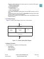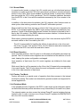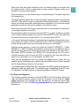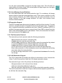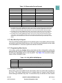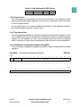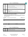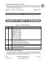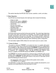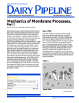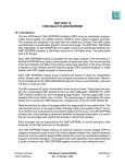
1
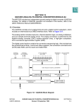
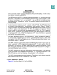
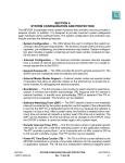
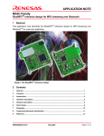
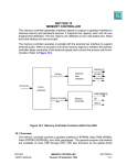
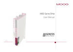
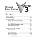
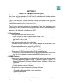
SECTION 11
L-BUS TO U-BUS INTERFACE (L2U)
The L-bus to U-bus interface unit (L2U) provides an interface between the load/store
bus (L-bus) and the unified bus (U-bus). The L2U module includes the data memory
protection unit (DMPU), which provides protection for data memory accesses.
The L2U is bi-directional. It allows load/store accesses not intended for the L-bus data
RAM to go to the U-bus. It also allows code execution from the L-bus data RAM and
read/write accesses from the U-bus to the L-bus.
The L2U directs bus traffic between the L-bus and the U-bus. When transactions start
concurrently on both buses, the L2U interface arbitrates to select which transaction is
handled. The top priority is assigned to U-bus to L-bus accesses; lower priority is
assigned to the load/store accesses by the RCPU.
11.1 General Features
• Non-pipelined master and slave on U-bus
— Does not start two back-to-back accesses on the U-bus
— Supports the U-bus pipelining by starting a cycle on the U-bus when U-bus
pipe depth is zero or one
— Does not accept back-to-back accesses from the U-bus master
• Non-pipelined master and slave on the L-bus
• Generates module selects for L-bus memory-mapped resources within a programmable, contiguous block of storage
• Programmable data memory protection unit (DMPU)
• L-bus and U-bus snoop logic for PowerPC reservation protocol
• L2U does not support dual mapping of L-bus or IMB3 space
• Show cycles for RCPU accesses to the SRAM (none, all, writes)
— Protection for SRAM accesses from the U-bus side (all accesses to the SRAM
from the U-bus side are blocked once the SRAM protection bit is set)
11.2 DMPU Features
• Supports four memory regions whose base address and size can be programmed
— Available sizes are 4 Kbytes, 8 Kbytes, 16 Kbytes, 32 Kbytes, 64 Kbytes, 128
Kbytes, 256 Kbytes, 512 Kbytes, 1 Mbyte, 2 Mbytes, 4 Mbytes, 8 Mbytes, and
16 Mbytes
— Region must start on the specified region size boundary
— Overlap between regions is allowed
• Each of the four regions supports the following attributes:
• Access protection: user or supervisor
• Guarded attribute: speculative or non-speculative
• Enable/disable option
• Read only option
MPC555
USER’S MANUAL
L-BUS TO U-BUS INTERFACE (L2U)
Revised 15 September 1999
MOTOROLA
11-1
• Supports a default global entry for memory space not covered by other regions:
— Default access protection
— Default guarded attribute
• Interrupt generated upon:
— Access violation
— Load from guarded region
— Write to read-only region
• The PowerPC MSR[DR] bit (data relocate) controls DMPU protection on/off operation
• Programming is done using PowerPC’s mtspr/mfspr instructions to/from implementation specific special purpose registers.
• No protection for accesses to the SRAM module on the L-bus (SRAM has its own
protection options)
11.3 L2U Block Diagram
Figure 11-1 shows a block diagram of the L-bus to U-bus interface.
L-bus
L-bus Interface
Address
Reservation
Decode
Control
DMPU
U-bus Interface
U-bus
Figure 11-1 L2U Bus Interface Block Diagram
11.4 Modes Of Operation
The L2U Module can operate in the following modes:
• Normal Mode
• Reset Operation
• Factory Test Mode
• Peripheral Mode
MPC555
USER’S MANUAL
L-BUS TO U-BUS INTERFACE (L2U)
Revised 15 September 1999
MOTOROLA
11-2
11.4.1 Normal Mode
In normal mode (master or slave) the L2U module acts as a bi-directional protocol
translator. In master mode the CPU is fully operational, and there is no external master
access to the U-bus. Slave mode enables an external master to access any internal
bus slave while the CPU is fully operational. The L2U transfers load/store accesses
from the RCPU to the U-bus and the read/write accesses by the U-bus master to the
L-bus.
In addition to the bus protocol translation, the L2U supports other functions such as
show cycles, data memory protection and PowerPC reservation protocol.
When a load from the U-bus resource or store to the U-bus resource is issued by the
RCPU, it is compared against the DMPU region access (address and attribute) comparators. If none of the access attributes are violated, the access is directed to the Ubus by the L2U module. If the DMPU detects an access violation, it informs the error
status to the master initiating the cycle.
When show cycles are enabled, accesses to all of the L-bus resources by the RCPU
are made visible on the U-bus side by the L2U.
The L2U is responsible for handling the effects of reservations on the L-bus and
the U-bus. For the L-bus and the U-bus, the L2U detects reservation losses and
updates the RCPU core with the reservation status.
11.4.2 Reset Operation
Upon soft reset assertion, the L2U goes to an idle state and all pending accesses are
ignored. The L2U module control registers are not initialized on the assertion of a soft
reset, keeping the system configuration unchanged.
Upon assertion of hard reset, the L2U control registers are initialized to their reset
states.
While reset (hard or soft) is asserted on the U-bus, the L2U asserts the corresponding
L-bus reset signals. The L2U also drives the reset configuration word from the U-bus
to the L-bus upon assertion of hard reset.
11.4.3 Factory Test Mode
Factory test mode is a special mode of operation that allows access to the internal
modules for testing. This mode is not intended for general use and is not supported for
normal applications.
11.4.4 Peripheral Mode
In the peripheral mode of operation the RCPU is shut down and an alternative master
on the external bus can perform accesses to any internal bus (U-bus and L-bus) slave.
The external master can also access the internal PowerPC special registers that are
located in L2U. In order to access one of these PowerPC registers the EMCR[CONT]
bit in the USIU must be cleared.
MPC555
USER’S MANUAL
L-BUS TO U-BUS INTERFACE (L2U)
Revised 15 September 1999
MOTOROLA
11-3
11.5 Data Memory Protection
The data memory protection unit (DMPU) in the L2U module provides access protection for the memory regions on the U-bus side from load/store accesses by the RCPU.
(Only U-bus space is protected.) The DMPU does not protect PowerPC register
accesses initiated by the RCPU on the L-bus. The user can assign up to four regions
of access protection attributes and can assign global attributes to any space not
included in the active regions. When it detects an access violation, the L2U generates
an exception request to the CPU.
Access attribute
Address
Region0 Address and size
Region1 Address and size
Region2 Address and size
Region3 Address and size
Match
select
Region0 protection/attribute
Region1 protection/attribute
Region2 protection/attribute
Region3 protection/attribute
Global protection/attribute
Specific
Error Interrupts
to Core
RegionProtection/Attribute
MSRDR
Exception
Logic
ACCESS
GRANTED
Figure 11-2 DMP Basic Functional Diagram
11.5.1 Functional Description
Data memory protection is assigned on a regional basis. Default manipulation of the
DMPU is done on a global region. The DMPU has control registers which contain the
following information: region protection on/off, region base address, region size, and
the region’s access permissions. Each region’s protection attributes can be turned on/
off by configuring the enable attribute bit (ENRx) located in the global region attribute
register.
During each load/store access from the RCPU core to the U-bus, the address is compared to the value in the region base address register of each enabled region. Any
access that matches the specific region within its appropriate size, as defined by the
region size field (RS) of the region attribute register, sets a match indication.
MPC555
USER’S MANUAL
L-BUS TO U-BUS INTERFACE (L2U)
Revised 15 September 1999
MOTOROLA
11-4
When more than one match indication occurs, the effective region is the region with
the highest priority. Priority is determined by region number; highest priority corresponds to the lowest region number.
When no match occurs, the effective region is the global region. The global region has
the lowest priority.
The region attribute register also contains the region’s protection fields. The protection
field (PP) of the effective region is compared to the access attributes. If the attributes
match, the access is permitted. When the access is permitted, a U-bus access may be
generated according to the specific attribute of the effective region.
When the access by the RCPU is not permitted, the L2U module asserts a data memory storage exception to the RCPU.
For speculative load/store accesses from the RCPU to a region marked as guarded
(G bit of region attribute register is set), the L2U asks the RCPU to retry the L-bus cycle
until either the access is not speculative, or it is canceled by the RCPU.
In the case of attempted accesses to a guarded region together with any other protection violation (no access), the L2U retries the access. The L2U handles this event as
a data storage violation only when the access becomes non-speculative.
Note that access protection is active only when the PowerPC’s MSR[DR] = 1. When
MSR[DR] = 0, DMPU exceptions are disabled, all accesses are considered to be to a
guarded memory area, and no speculative accesses are allowed. In this case, if the Lbus master [RCPU] initiates a non-SRAM cycle (access through the L2U) that is
marked speculative, the L2U asks the RCPU to retry the L-bus cycle until either the
access is not speculative, or it is canceled by the RCPU Core.
Note that the programmer must not overlap the SRAM memory space with any
enabled region. Overlapping an enabled region with SRAM memory space disables
the L2U data memory protection for that region.
If an enabled region overlaps with the L-bus space, the DMPU ignores all accesses to
addresses within the L-bus space. If an enabled region overlaps with PowerPC register addresses, the DMPU ignores any access marked as a PowerPC access.
11.5.2 Associated Registers
The following registers are used to control the DMPU of the L2U module. All the registers are special purpose registers which are accessed via the PowerPC mtspr/
mfspr instructions. The registers are also accessed by an external master when
EMCR[CONT] = 0. See 11.8 L2U Programming Model for register diagrams and bit
descriptions.
MPC555
USER’S MANUAL
L-BUS TO U-BUS INTERFACE (L2U)
Revised 15 September 1999
MOTOROLA
11-5
.
Table 11-1 DMPU Registers
Name
Description
L2U_RBA0
Region Base Address Register 0
L2U_RBA1
Region Base Address Register 1
L2U_RBA2
Region Base Address Register 2
L2U_RBA3
Region Base Address Register 3
L2U_RA0
Region Attribute Register 0
L2U_RA1
Region Attribute Register 1
L2U_RA2
Region Attribute Register 2
L2U_RA3
Region Attribute Register 3
L2U_GRA
Global Region Attribute
CAUTION
The appropriate DMPU registers must be programmed before the
MSR[DR] bit is set. Otherwise, DMPU operation is not guaranteed.
Program the region base address in the L2U_RBAx registers to the lower boundary of
the region specified by the corresponding L2U_RAx[RS] field. If the region base
address does not correspond to the boundary of the block size programmed in the
L2U_RAx, the DMPU snaps the region base to the lower boundary of that block. For
example, if the block size is programmed to 16 Kbytes for region zero (i.e.
L2U_RA0[RS] = 0 x 3) and the region base address is programmed to 0x1FFF(i.e.,
L2U_RBA0[RBA] = 0 x 1), then the effective base address of region zero is 0 x 0. See
Figure 11-3.
0x00000000
region 0
(16 Kbytes)
Resulting Region
0x00001FFF
Actual Programmed Region
0x00003FFF
0x00005FFF
Figure 11-3 Region Base Address Example
MPC555
USER’S MANUAL
L-BUS TO U-BUS INTERFACE (L2U)
Revised 15 September 1999
MOTOROLA
11-6
It is the user’s responsibility to program only legal region sizes. The L2U does not
check whether the value is legal. If the user programs an illegal region size, the region
calculation may not be successful.
11.5.3 L-bus Memory Access Violations
All L-bus slaves have their own access protection logic. For consistency, all storage
access violations have the same termination result. Thus access violations for load/
store accesses started by the RCPU always have the same termination from all
slaves: assertion of the data storage exception. All other L-bus masters cause
machine check exceptions.
11.6 Reservation Support
The RCPU storage reservation protocol supports a multi-level bus structure. For each
local bus, storage reservation is handled by the local reservation logic. The protocol
tries to optimize reservation cancellation such that a PowerPC processor (RCPU) is
notified of storage reservation loss on a remote bus (U-bus, IMB or external bus) only
when it has issued a stwcx cycle to that address. That is, the reservation loss indication comes as part of the stwcx cycle.
11.6.1 The Reservation Protocol
The reservation protocol operates under the following assumptions:
• Each processor has at most 1 reservation flag
• A lwarx instruction sets the reservation flag
• Another lwarx instruction by same processor clears the reservation flag related
to a previous lwarx instruction and sets again the reservation flag
• A stwcx instruction by same processor clears the reservation flag
• A store instruction by same processor does not clear the reservation flag
• Some other processor (or other mechanism) store to an address with an existing
reservation clears the reservation flag
• In case the storage reservation is lost, it is guaranteed that stwcx will not modify
the storage
11.6.2 L2U Reservation Support
The L2U is responsible for handling the effects of reservations on the L-bus and the
U-bus. For the L-bus and the U-bus, the L2U detects reservation losses.
The reservation logic in the L2U performs the following functions:
• Snoops accesses to all L-bus and U-bus slaves
• Holds one reservation (address) for the core
• Sets the reservation flag when the CPU issues a load-with-reservation request
The unit for reservation is one word. A byte or half-word store request by another master will clear the reservation flag.
MPC555
USER’S MANUAL
L-BUS TO U-BUS INTERFACE (L2U)
Revised 15 September 1999
MOTOROLA
11-7
A load-with-reservation request by the CPU updates the reservation address related
to a previous load-with-reservation request and sets the reservation flag for the new
location. A store-with-reservation request by the CPU clears the reservation flag. A
store request by the CPU does not clear the flag. A store request by some other master
to the reservation address clears the reservation flag.
If the storage reservation is lost, it is guaranteed that a store-with-reservation request
by the CPU will not modify the storage.
The L2U does not start a store-with-reservation cycle on the U-bus if the reserved
location on the U-bus has been touched by another master. The L2U drives the reservation status back to the core.
When the reserved location in the SRAM on the L-bus is touched by an alternate master, on the following clock, the L2U indicates to the CPU that the reservation has been
touched. On assertion of the cancel-reservation signal, the RCPU clears the internal
reservation bit. If an stwcx cycle has been issued at the same time, the RCPU aborts
the cycle.
Storage reservation is set regardless of the termination status (address or data phase)
of the lwarx access. Storage reservation is cleared regardless of the data phase termination status of the stwcx access if the address phase is terminated normally.
Storage reservation will be cleared regardless of the data phase termination status of
the write requests by another master to the reserved address if the address phase of
the write access is terminated normally on the destination (U-bus/L-bus) bus.
If the programmable memory map of the part is modified between a lwarx and a stwcx
instruction, the reservation is not guaranteed.
11.6.3 Reserved Location (Bus) and Possible Actions
Once the CPU core reserves a memory location, the L2U module is responsible for
snooping L-bus and U-bus for possible intrusion of the reserved location. Under certain circumstances, the L2U depends on the USIU or the UIMB to provide status of
reservation on external bus and the IMB3 respectively.
Table 11-2 lists all reservation protocol cases supported by the L2U snooping logic.
MPC555
USER’S MANUAL
L-BUS TO U-BUS INTERFACE (L2U)
Revised 15 September 1999
MOTOROLA
11-8
Table 11-2 Reservation Snoop Support
Reserved Location On
Intruding Alternate Master
L-bus
L-Master
Request to cancel the reservation.1
U-Master
Request to cancel the reservation.
L-Master
Block stwcx2
U-Master
Block stwcx
L-Master
Block stwcx
U-Master
Block stwcx
U-bus
External Bus
Ext-Master
IMB3
Action Taken on stwcx cycle
Transfer Status3
L-Master
Block stwcx
U-Master
Block stwcx
IMB3-Master
Transfer Status
NOTES:
1. If the RCPU tries to modify (stwcx) that location, the L2U does not have enough time to stop the write
access from completing. In this case, the L2U will drive cancel-reservation signal back to the core as
soon as it comes to know that the alternate master on the U-bus has touched the reserved location.
2. If the RCPU tries to modify (stwcx) that location, the L2U does not start the cycle on the U-bus and it
communicates to the core that the current write has been aborted by the slave with no side effects.
3. If the RCPU tries to modify (stwcx) that location, the L2U runs a write-cycle-with-reservation request
on the U-bus. The L2U samples the status of the reservation along with the U-bus cycle termination
signals and it communicates to the core if the current write has been aborted by the slave with no side
effects.
11.7 L-Bus Show Cycle Support
The L2U module provides support for L-bus show cycles. L-bus show cycles are external visibility cycles that reflect activity on the L-bus that would otherwise not be visible
to the external bus. L-bus show cycles are software controlled.
11.7.1 Programming Show Cycles
L-bus show cycles are disabled during reset and must be configured by writing the
appropriate bits in the L2U_MCR control register. L-bus show cycles are programmed
by setting the LSHOW[0:1] bits in the L2U_MCR. The Table 11-3 shows the configurations of the LSHOW[0:1] bits.
Table 11-3 L2U_MCR LSHOW Modes
LSHOW
Action
00
Disable L-bus show cycles
01
Show address and data of all L-bus space write cycles
10
Reserved (Disable L-bus show cycles)
11
Show address and data of all L-bus space read and write cycles
11.7.2 Performance Impact
When show cycles are enabled in the L2U module, there is a performance penalty on
the L-bus. This occurs because the L2U module does not support more than one
access being processed at any time. To ensure that only one access at a time can be
MPC555
USER’S MANUAL
L-BUS TO U-BUS INTERFACE (L2U)
Revised 15 September 1999
MOTOROLA
11-9
processed, and not lose an L-bus access that would have been show cycled, the L2U
module will arbitrate for the L-bus whenever it is processing any access. This L-bus
arbitration will prevent any other L-bus master from starting a cycle that might turn out
to be a qualifiable L-bus show cycle.
For L-bus show cycles, the minimum performance impact on the L-bus will be three
clocks. This minimum impact assumes that the L-bus slave access is a 1-clock access,
and the L2U module acquires immediate bus grant on the U-bus. The L2U has to wait
two clocks before completing the show cycle on the U-Bus, thus using up five clocks
for the complete process.
A retried access on the L-bus (no address acknowledge) that qualifies to be show
cycled, will be accepted when it is actually acknowledged. This will cause a 1-clock
delay before an L-bus master can retry the access on the L-bus, because the L2U
module will release L-bus one clock later.
L2U asserts the internal bus request signal on the U-bus for a minimum of two clocks
when starting a show cycle on the U-bus.
11.7.3 Show Cycle Protocol
The L2U module behaves as both a master and a slave on the U-bus during show
cycles. The L2U starts the U-bus transfer as a a bus master and then completes the
address phase and data phase of the cycle as a slave. The L2U follows U-bus protocol
of in-order termination of the data phase.
The USIU can control the start of show cycles on the U-bus by asserting the no-show
cycle indicator. This will cause the L2U module to release the U-bus for at least one
clock before retrying the show cycle.
11.7.4 L-Bus Write Show Cycle Flow
The L2U performs the following sequence of actions for an L-bus-write show cycle.
1. Arbitrates for the L-bus to prevent any other L-bus cycles from starting
2. Latches the address and the data of the L-bus access, along with all address
attributes
3. Waits for the termination of the L-bus access and latches the termination status
(data error)
4. Arbitrate for the U-bus, and when granted, starts the U-bus access, asserting
show cycle request on the U-bus, along with address, attributes and the write
data. The L2U module provides address recognize and acknowledgment for
the address phase. If the no-show cycle indicator from the U-bus is asserted,
the L2U does not start the show cycle. The L2U module releases the U-bus until
the no-show cycle indicator is negated and then arbitrates for the U-bus again.
5. When the L2U module has U-bus data bus grant, it drives the data phase termination handshakes on the U-bus.
6. Releases the L-bus
MPC555
USER’S MANUAL
L-BUS TO U-BUS INTERFACE (L2U)
Revised 15 September 1999
MOTOROLA
11-10
11.7.5 L-Bus Read Show Cycle Flow
The L2U performs the following sequence of actions for an L-bus read show cycle.
1. Arbitrates for the L-bus to prevent any other L-bus cycle from starting
2. Latches the address of the L-bus access, along with all address attributes
3. Waits for the data phase termination on the L-bus and latch the read data, and
the termination status from the L-bus
4. Arbitrate for the U-bus, and when granted, starts the U-bus access, asserting
the show cycle request on the U-bus, along with address attributes. The L2U
module provides address recognize/acknowledgment for the address phase. If
the no-show cycle indicator from the U-bus is asserted, the L2U does not start
the show cycle. The L2U module releases the U-bus until the no-show cycle indicator is negated and then arbitrates for the U-bus again.
5. When the L2U module has U-bus data bus grant, it drives the read data and the
data phase termination handshakes on the U-bus
6. Release the L-bus.
11.7.6 Show Cycle Support Guidelines
The following are the guidelines for L2U show cycle support:
• The L2U module provides address and data for all qualifying L-bus cycles when
the appropriate mode bits are set in the L2U_MCR.
• The L2U-module-only show cycles L-bus activity that is not targeted for the U-bus
or the L2U module internal registers, irrespective of the termination status of such
activity.
• The L2U module does not show cycle any access to a PowerPC special purpose
register.
• The L2U does not start a show cycle for an L-bus access that is retried. This decision to not start the show cycle causes a clock delay before the cycle can be
retried, since the L2U module will have arbitrated away the L-bus immediately on
detecting the show cycle, before the retry information is available.
• The L2U module does not show cycle any L-bus activity that is aborted.
• The L2U module backs off the U-bus if the USIU inhibits show cycle activity on
the U-bus.
• The L2U does not show cycle any L-bus addresses that fall in the L-bus SRAM
address space if the SRAM Protection [SP] bit is set in the L2U_MCR.
Table 11-4 summarizes the L2U show cycle support.
MPC555
USER’S MANUAL
L-BUS TO U-BUS INTERFACE (L2U)
Revised 15 September 1999
MOTOROLA
11-11
Table 11-4 L2U Show Cycle Support Chart
Case
Destination
LB AACK
LB ABORT
Comments
1
L-bus Slave1
No
X
Not show cycled
[Cycle will be retried one clock later]4
2
L2U 2
X
X
Not show cycled
X
X
Not show cycled
3
3
U-bus/E-bus
4
L-bus slave
Yes
No
Show cycled
5
L-bus slave
Yes
Yes
Not show cycled
[L-bus will be released next clock]
1. L-bus slave includes all address in the L-bus address space.
2. L2U indicates L2U registers.
3. U-bus/E-bus refers to all destinations through the L2U interface.
4. There will be a 1-clock turnaround because the L-bus retry information is not available in time to negate the Lbus arbitration.
Note: X indicates don’t care conditions.
11.8 L2U Programming Model
The L2U control registers control the L2U bus interface and the DMPU. They are
accessible via the MPC555 mtspr and mfspr instructions. They are also accessible
by an external master when EMCR[CONT] bit is cleared. L2U control registers are
accessible from both the L-bus side and the U-bus side in one clock cycle. As with all
SPRs, L2U registers are accessible in supervisor mode only.
Any unimplemented bits in L2U registers return 0’s on a read, and the writes to those
register bits are ignored.
The Table 11-5 shows L2U registers along with their SPR numbers and hexadecimal
addresses which are used to access L2U registers during a peripheral mode access.
.
Table 11-5 L2U (PPC) Register Decode
Name
SPR #
SPR5:9
SPR0:4
Address for
External Master
Access
Access
Description
L2U_MCR
568
10001
11000
0x0000_3110
SUPR
L2U Module Configuration Register
L2U_RBA0
792
11000
11000
0x0000_3180
SUPR
Region Base Address Register 0
L2U_RBA1
793
11000
11001
0x0000_3380
SUPR
Region Base Address Register 1
L2U_RBA2
794
11000
11010
0x0000_3580
SUPR
Region Base Address Register 2
L2U_RBA3
795
11000
11011
0x0000_3780
SUPR
Region Base Address Register 3
L2U_RA0
824
11001
11000
0x0000_3190
SUPR
Region Attribute Register 0
L2U_RA1
825
11001
11001
0x0000_3390
SUPR
Region Attribute Register 1
L2U_RA2
826
11001
11010
0x0000_3590
SUPR
Region Attribute Register 2
L2U_RA3
827
11001
11011
0x0000_3790
SUPR
Region Attribute Register 3
L2U_GRA
536
10000
11000
0x0000_3100
SUPR
Global Region Attribute
For these registers a bus cycle will be performed on the L-bus and the U-bus with the
address as shown inTable 11-6.
MPC555
USER’S MANUAL
L-BUS TO U-BUS INTERFACE (L2U)
Revised 15 September 1999
MOTOROLA
11-12
.
Table 11-6 Hex Address For SPR Cycles
A0:17
A18:22
A23:27
A28:31
0
spr0:4
spr5:9
0
11.8.1 U-bus Access
The L2U registers are accessible from the U-bus side only if it is a supervisor mode
data access and the register address is correct and it is indicated on the U-bus that it
is a PPC register access.
A user mode access, or an access marked as instruction, to L2U registers from the Ubus side will cause a data error on the U-bus.
11.8.2 Transaction Size
All L2U registers are defined by PowerPC architecture as being 32-bit registers. There
is no PowerPC instruction to access either a half word or a byte of the special purpose
register. All L2U registers are only word accessible (read and write) in peripheral
mode. A half-word or byte access in peripheral mode will result in a word transaction.
11.8.3 L2U Module Configuration Register (L2U_MCR)
The L2U module configuration register (L2U_MCR) is used to control the L2U module
operation.
L2U_MCR — L2U Module Configuration Register
MSB
0
SP
1
2
3
4
5
6
7
8
LSHOW
SPR 568
9
10
11
12
13
14
15
RESERVED
RESET:
0
0
0
0
0
0
0
0
0
0
0
0
0
0
0
0
16
17
18
19
20
21
22
23
24
25
26
27
28
29
30
LSB
31
0
0
0
0
0
0
0
RESERVED
RESET:
0
0
0
MPC555
USER’S MANUAL
0
0
0
0
0
0
L-BUS TO U-BUS INTERFACE (L2U)
Revised 15 September 1999
MOTOROLA
11-13
Table 11-7 L2U_MCR Bit Settings
Bit(s)
Name
Description
SRAM Protection (SP) bit is used to protect the SRAM on the L-bus from U-bus accesses.
This bit can be set or cleared from the L-bus side. It can be set or cleared from the U-bus side
when factory test mode is enabled. When not in factory test mode, any attempt to set or clear the
SP bit from the U-bus side has no affect.
0
SP
Once this bit is set, the L2U blocks all SRAM accesses initiated by the U-bus masters and the
access is terminated with a data error on the U-bus.
If L-bus show cycles are enabled, setting this bit will disable L-bus SRAM show cycles.
1:2
LSHOW
3:31
—
LSHOW bits are used to configure the show cycle mode for cycles accessing the L-bus slave e.g.
SRAM
00 = Disable show cycles
01 = Show address and data of all L-bus space write cycles
10 = Reserved
11 = Show address and data of all L-bus space read and write cycles
Reserved
11.8.4 Region Base Address Registers (L2U_RBAx)
The region base address register defines the base address of a specific region protected by the data memory protection unit. There are four registers (x = 0...3), one for
each supported region.
L2U_RBAx — L2U Region x Base Address Register
MSB
0
1
2
3
4
5
6
7
SPR 792 – 795
8
9
10
11
12
13
14
15
RBA
RESET:
x
x
x
x
x
x
x
x
x
x
x
x
x
x
x
x
16
17
18
19
20
21
22
23
24
25
26
27
28
29
30
LSB
31
0
0
0
0
0
RBA
RESERVED
RESET:
x
x
x
x
0
0
0
0
0
0
0
x = Undefined
Table 11-8 L2U_RBAx Bit Settings
Bit(s)
Name
Description
0:19
RBA
Region base address. The RBA field provides the base address of the region. The region base
address should start on the block boundary for the corresponding block size attribute specified
in the region attribute register (L2U_RAx).
20:31
—
MPC555
USER’S MANUAL
Reserved
L-BUS TO U-BUS INTERFACE (L2U)
Revised 15 September 1999
MOTOROLA
11-14
11.8.5 Region Attribute Registers (L2U_RAx)
Each region attribute register defines the protection attributes associated with a specific region protected by the data memory protection unit. There are four registers (x =
0...3), one for each supported region.
L2U_RAx — L2U Region X Attribute Register
MSB
0
1
2
3
4
5
6
7
SPR 824 – 827
8
9
10
11
RESERVED
12
13
14
15
RS
RESET:
0
0
0
0
0
0
0
0
0
0
0
0
0
0
0
0
16
17
18
19
20
21
22
23
24
25
26
27
28
29
30
LSB
31
0
0
RS
PP
RESERVED
G
RESERVED
RESET:
0
0
0
0
0
0
0
0
0
0
0
0
0
0
Table 11-9 L2U_RAx Bit Settings
Bit(s)
Name
0:7
—
Reserved
RS
Region size
0000_0000_0000 = 4 Kbytes
0000_0000_0001 = 8 Kbytes
0000_0000_0011 = 16 Kbytes
0000_0000_0111 = 32 Kbytes
0000_0000_1111 = 64 Kbytes
0000_0001_1111 = 128 Kbytes
0000_0011_1111 = 256 Kbytes
0000_0111_1111 = 512 Kbytes
0000_1111_1111 = 1 Mbyte
0001_1111_1111 = 2 Mbytes
0011_1111_1111 = 4 Mbytes
0111_1111_1111 = 8 Mbytes
1111_1111_1111 = 16 Mbytes
20:21
PP
Protection bits
00 = No supervisor access, no user access
01 = Supervisor read/write access, no user access
10 = Supervisor read/write access, user read-only access
11 = Supervisor read/write access, user read/write access
22:24
—
Reserved
25
G
Guarded attribute
0 = Not guarded from speculative accesses
1 = Guarded from speculative accesses
26:31
—
Reserved
8:19
Description
11.8.6 Global Region Attribute Register
The global region attribute register defines the protection attributes associated with the
memory region which is not protected under the four DMPU regions. This register also
provides enable/disable control for the four DMPU regions.
MPC555
USER’S MANUAL
L-BUS TO U-BUS INTERFACE (L2U)
Revised 15 September 1999
MOTOROLA
11-15
L2U_GRA — L2U Global Region Attribute Register
MSB
0
1
2
3
4
5
6
7
8
SPR 536
9
ENR0 ENR1 ENR2 ENR3
10
11
12
13
14
15
RESERVED
RESET:
0
0
0
0
0
0
0
0
0
0
0
0
0
0
0
0
16
17
18
19
20
21
22
23
24
25
26
27
28
29
30
LSB
31
0
0
RESERVED
PP
RESERVED
G
RESERVED
RESET:
0
0
0
0
0
0
0
0
0
0
0
0
0
0
Table 11-10 L2U_GRA Bit Settings
Bit(s)
Name
0
ENR0
Enable attribute for region 0
0 = Region attribute is off
1 = Region attribute is on
1
ENR1
Enable attribute for region 1
0 = Region attribute is off
1 = Region attribute is on
2
ENR2
Enable attribute for region 2
0 = Region attribute is off
1 = Region attribute is on
3
ENR3
Enable attribute for region 3
0 = Region attribute is off
1 = Region attribute is on
4:19
—
Reserved
20:21
PP
Protection bits
00 = No supervisor access, no user access
01 = Supervisor read/write access, no user access
10 = Supervisor read/write access, user read-only access
11 = Supervisor read/write access, user read/write access
22:24
—
Reserved
25
G
Guarded attribute
0 = Not guarded from speculative accesses
1 = Guarded from speculative accesses
26:31
—
Reserved
MPC555
USER’S MANUAL
Description
L-BUS TO U-BUS INTERFACE (L2U)
Revised 15 September 1999
MOTOROLA
11-16