1
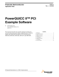
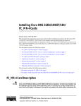
Freescale Semiconductor, Inc.
Rev. 0, 02/2003
Freescale Semiconductor, Inc...
Initializing Flash Memory for
the MPC8260ADS
The MPC8260ADS (Application Development System—ADS) can be initialized and
configured with data from the programmable Board Control and Status Registers (BCSRx)
located on the ADS board or the Hard Reset Configuration Word (HRCW) located in Flash.
The initial configuration of the clock is determined at power-on reset from the values that are
driven to the MODCK[1:3] pins at power-on reset. A DIP switch, located on the ADS board,
is used to specify the values that are driven on the MODCK pins and to indicate that the Hard
Reset Configuration Word is located in Flash.
1
References
Table 1. References
Document
2
Identification Number
MPC8260 PowerQUICC II™ User’s Manual
MPC8260UM/D
MPC8260 PowerQUICC II™ User’s Manual Errata
MPC8260UMAD/D
MPC8260 PowerQUICC II™ Hardware Specifications
MPC8260EC/D
MPC8260ADS User’s Manual
MPC8260ADS
Clock Initialization
Clock initialization takes place during the power-on reset event. Switch settings for DIP
switch DS1[6-8] on the MPC8260ADS select input values for the MODCK[1:3] pins (see
Table 2). The values placed on the MODCK pins can be controlled by placing the DIP switch
in either the ON or OFF position. When configuring the initial clock configuration mode,
placing the switch in the “ON” position forces a zero on the respective MODCK pin, while
placing the switch in the “OFF” position forces a one. For example, if using a 66MHz crystal
oscillator, placing DS1[6:8] OFF-ON-ON, will result in MODCK[1:3] values of 0b100 which
will result in a 66MHz input clock and bus speed, a 133MHz CPM and a 166MHz Core.
Additional clocking options can be achieved with the MODCK_H values set in the Hard Reset
Configuration Word (see Table 3).
© Freescale Semiconductor, Inc., 2004. All rights reserved.
For More Information On This Product,
Go to: www.freescale.com
Freescale Semiconductor, Inc.
Reset Initialization
Freescale Semiconductor, Inc...
Table 2. Clock Default Modes
MODCK[1–3]
Input Clock
Frequency
CPM Multiplication
Factor
CPM
Frequency
Core Multiplication
Factor
Core
Frequency
000
33 MHz
3
100 MHz
4
133 MHz
001
33 MHz
3
100 MHz
5
166 MHz
010
33 MHz
4
133 MHz
4
133 MHz
011
33 MHz
4
133 MHz
5
166 MHz
100
66 MHz
2
133 MHz
2.5
166 MHz
101
66 MHz
2
133 MHz
3
200 MHz
110
66 MHz
2.5
166 MHz
2.5
166 MHz
111
66 MHz
2.5
166 MHz
3
200 MHz
3
Reset Initialization
The MPC8260 can be initialized from reset in three ways. Two of the ways toggle the RSTCONF pin to
latch the Hard Reset Configuration Word (HRCW) from the data bus, similar to the MPC8xx reset
methodology, as described in the MPC860 PowerQUICC™ User’s Manual.
The third and most common method uses the memory controller to access the area controlled by CS0, the
global chip select, of the configuration master to fetch the HRCW from an EPROM (Flash). This method
can be implemented on the ADS board by placing the DS1[1] DIP switch to the “ON” position.
4
Hard Reset Configuration Word from CS0
During the HRCW event from CS0, certain initialization processes will occur as documented in the
MPC8260 PowerQUICC II™ User's Manual in Section 5.4.1 (HRCW). Because the port size of the initial
transfers isn't known at boot time, only the first byte (D[0-7]) of each 32 bit access is used, since the smallest
port size allowed is one byte.
Four 32-bit accesses are required to fetch the entire HRCW. Although each access fetches 32 bits, only the
most significant byte, bits 0-7, is used. The remaining 24 bits of each access are ignored. The accesses are
made when the CS0 (global chip select) memory controller accesess the data at address 0x00 for the first
byte of the HRCW, then address 0x08 for the second byte, and so on until the entire HRCW is fetched. Then,
the 32-bit access HRCW is packed on the bus and presented to the MPC8260.
0
1
2
3
Field EARB EXMC CDIS EBM
4
5
BPS
Reset
7
CIP
ISPS
8
9
L2CPC
10
11
DPPC
12
—
13
15
ISB
0000_0000_0000_0000
16
Field BMS
Reset
6
17
BBD
18
19
MMR
20
21
LBPC
22
23
APPC
24
25
26
CS10PC
27
—
0000_0000_0000_0000
Figure 1. Hard Reset Configuration Word
Initializing Flash Memory for the MPC8260ADS
For More Information On This Product,
Go to: www.freescale.com
28
31
MODCK_H
Freescale Semiconductor, Inc.
Hard Reset Configuration Word from CS0
Freescale Semiconductor, Inc...
Table 3. Hard Reset Configuration Word Field Descriptions
Bits
Name
Description
0
EARB 1
External arbitration. Defines the initial value for ACR[EARB]. If EARB = 1, external arbitration is
assumed. See Section 4.3.2.2, “60x Bus Arbiter Configuration Register (PPC_ACR).”
1
EXMC
External MEMC. Defines the initial value of BR0[EMEMC]. If EXMC = 1, an external memory
controller is assumed. See Section 10.3.1, “Base Registers (BRx).”
2
CDIS1
Core disable. Defines the initial value for the SIUMCR[CDIS].
0 The core is active. See Section 4.3.2.6, “SIU Module Configuration Register (SIUMCR).”
1 The core is disabled. In this mode the MPC8260 functions as a slave.
3
EBM1
External bus mode. Defines the initial value of BCR[EBM]. See Section 4.3.2.1, “Bus
Configuration Register (BCR).”
4–5
BPS
Boot port size. Defines the initial value of BR0[PS], the port size for memory controller bank 0.
00 64-bit port size
01 8-bit port size
10 16-bit port size
11 32-bit port size
See Section 10.3.1, “Base Registers (BRx).”
6
CIP1
Core initial prefix. Defines the initial value of MSR[IP]. Exception prefix. The setting of this bit
specifies whether an exception vector offset is prepended with Fs or 0s. In the following
description, nnnnn is the offset of the exception vector.
0 MSR[IP] = 1 (default). Exceptions are vectored to the physical address 0xFFFn_nnnn
1 MSR[IP] = 0 Exceptions are vectored to the physical address 0x000n_nnnn.
7
ISPS1
Internal space port size. Defines the initial value of BCR[ISPS]. Setting ISPS configures the
MPC8260 to respond to accesses from a 32-bit external master to its internal space. See
Section 4.3.2.1, “Bus Configuration Register (BCR).”
8–9
L2CPC1
L2 cache pins configuration. Defines the initial value of SIUMCR[L2CPC]. See Section 4.3.2.6,
“SIU Module Configuration Register (SIUMCR).”
10–11
DPPC1
Data parity pin configuration. Defines the initial value of SIUMCR[DPPC]. For more details refer
to Section 4.3.2.6, “SIU Module Configuration Register (SIUMCR).”
12
—
13–15
ISB
Initial internal space base select. Defines the initial value of IMMR[0–14] and determines the
base address of the internal memory space.
000 0x0000_0000
001 0x00F0_0000
010 0x0F00_0000
011 0x0FF0_0000
100 0xF000_0000
101 0xF0F0_0000
110 0xFF00_0000
111 0xFFF0_0000
See Section 4.3.2.7, “Internal Memory Map Register (IMMR).”
16
BMS
Boot memory space. Defines the initial value for BR0[BA]. There are two possible boot memory
regions: HIMEM and LOMEM.
0 0xFE00_0000—0xFFFF_FFFF
1 0x0000_0000—0x01FF_FFFF
See Section 10.3.1, “Base Registers (BRx).”
17
BBD
Bus busy disable. Defines the initial value of SIUMCR[BBD]. See Section 4.3.2.6, “SIU Module
Configuration Register (SIUMCR).”
Reserved, should be cleared.
Initializing Flash Memory for the MPC8260ADS
For More Information On This Product,
Go to: www.freescale.com
Freescale Semiconductor, Inc.
Configuring Additional Processors
Table 3. Hard Reset Configuration Word Field Descriptions (continued)
Bits
Name
18–19
MMR
20–21
LBPC1
Description
Mask masters requests. Defines the initial value of SIUMCR[MMR]. See Section 4.3.2.6, “SIU
Module Configuration Register (SIUMCR).”
Local bus pin configuration. Defines the value of SIUMCR[LBPC]. See Section 4.3.2.6, “SIU
Module Configuration Register (SIUMCR).”
Freescale Semiconductor, Inc...
00 Local bus pins function as local bus
01 Local bus pins function as PCI bus (MPC8265, MPC8266, MPC8250 only). Reserved on all
other devices.
10 Local bus pins function as core pins
11 Reserved
22–23
APPC1
24–25
CS10PC1
26–27
—
Address parity pin configuration. Defines the initial value of SIUMCR[APPC]. See
Section 4.3.2.6, “SIU Module Configuration Register (SIUMCR).”
CS10 pin configuration. Defines the initial value of SIUMCR[CS10PC]. See Section 4.3.2.6, “SIU
Module Configuration Register (SIUMCR).”
Reserved, should be cleared.
28–31 MODCK_H High-order bits of the MODCK bus, which determine the clock reset configuration. See
Chapter 9, “Clocks and Power Control,” for details. (If the device has PCI and is configured to PCI
mode (PCI_MODE is driven low), this field has no effect and the value for MODCK_H is loaded
directly from the MODCK_H pins. Note that the value of the MODCK_H bits are derived from the
dedicated PCI_MODCK_H[0:3] pins when operating in PCI mode. )
1
5
The user should exercise caution when changing this bit. This bit has an immediate effect on the external bus and
may resultin unstable system operation.
Configuring Additional Processors
If additional devices are to be configured by this processor, then this process continues in a similar manner,
with the addresses incrementing as before, until as many as 7 additional processors are configured. This is
explained in further detail in the User's Manual in Section 5.4 (Reset Configuration) and Section 5.4.2.3
(Multiple 8260's with boot EPROM). The process requires the configuration slave devices to have their
RSTCONF pins tied to the configuration master's address lines (A[0-6] for slave 1-7, respectively).
Table 4. Configuration EPROM Addresses
Configured Device
Byte 0 Address
Byte 1 Address
Byte 2 Address
Byte 3 Address
Configuration master
0x00
0x08
0x10
0x18
First configuration slave
0x20
0x28
0x30
0x38
Second configuration slave
0x40
0x48
0x50
0x58
Third configuration slave
0x60
0x68
0x70
0x78
Fourth configuration slave
0x80
0x88
0x90
0x98
Fifth configuration slave
0xA0
0xA8
0xB0
0xB8
Sixth configuration slave
0xC0
0xC8
0xD0
0xD8
Seventh configuration slave
0xE0
0xE8
0xF0
0xF8
Initializing Flash Memory for the MPC8260ADS
For More Information On This Product,
Go to: www.freescale.com
Freescale Semiconductor, Inc.
Initialization Code
6
Initialization Code
Freescale Semiconductor, Inc...
We will use the initialization code titled INIT Example (works with ENG and PILOT revs of MPC8260ADS)
under the heading Code Examples from the MPC8260 page of our website. This example sets up interrupt
vectors, the hard reset configuration word, the memory controller for the ADS board (this can also be used
as a guide for the memory controller setup for your target board) as well as general System Interface Unit
parameters and a UART for demonstration purposes. The following is a list of the files contained in the ZIP:
Init8260.s
Initialization file
Init8260.h
Header file for init8260.s
config.s
Hard Reset Configuration Word
8260_int.s
Exceptions
vect_tbl.s
Vector Exception Table Definitions
uart.c
Source file for UART character echo and LED flashing
uart.h
Header file for uart.c
masks8260.h
Standard masks for MPC8260 software
mpc8260.h
Internal memory map structure declarations for MPC8260
netcomm.h
Global data type definitions
init8260.map
Included for informational purpose
makefile
MKS makefile
init8260.out
Downloadable ELF with symbol table file
init8260.s3
S record file
init8260.lnx
Link command file
These files contain all of the necessary components to compile an image that will boot and initialize the
MPC8260ADS. Equipment capable of writing an image to a Flash memory module will be required.
7
MPC8260ADS Board
In order to boot from Flash, rather than the Board Control and Status Registers, you must change DS1[1]
to the ON position (marked Flash on the PCB). This will allow the processor to boot from the Hard Reset
Configuration Word located in Flash Memory in address location of CS0. Depending on the type of Flash
Module, the user may also be required to supply power to the Vpp connector P2. Refer to the Flash
Manufacturer’s data sheet for information on the power requirements for Vpp.
8
Initialization of ADS Board
Apply power and allow board to boot from Flash. The Serial Communication Controller (SCC1) will be
configured from Flash to permit a 9600,1,0,n UART to the serial port, PA3, for echo demonstration of
software. Also, a signaling LED will flash to indicate that the initialization was successful.
Initializing Flash Memory for the MPC8260ADS
For More Information On This Product,
Go to: www.freescale.com
Freescale Semiconductor, Inc.
Flash Memory Map
9
Flash Memory Map
The memory map is as follows:
0x0000 – 0x00FF
Hard Reset Configuration Word
0x0100 – 0x0FFF
Exception Vectors
0x1000 – 0xFFFF
ADS Initialization Code
0x10000 – 0x01FFFFFF
Demo Software (up to 32M Flash support)
Freescale Semiconductor, Inc...
10 Summary
By programming the Flash with a proven initialization sequence, the user can place their custom code in
unused locations in Flash to test suitability with their operating system and the software interaction effects.
Initializing Flash Memory for the MPC8260ADS
For More Information On This Product,
Go to: www.freescale.com
Freescale Semiconductor, Inc.
Freescale Semiconductor, Inc...
Summary
Initializing Flash Memory for the MPC8260ADS
For More Information On This Product,
Go to: www.freescale.com
Freescale Semiconductor, Inc.
How to Reach Us:
Home Page:
www.freescale.com
Freescale Semiconductor, Inc...
E-mail:
[email protected]
USA/Europe or Locations Not Listed:
Freescale Semiconductor
Technical Information Center, CH370
1300 N. Alma School Road
Chandler, Arizona 85224
+1-800-521-6274 or +1-480-768-2130
[email protected]
Europe, Middle East, and Africa:
Freescale Halbleiter Deutschland GmbH
Technical Information Center
Schatzbogen 7
81829 Muenchen, Germany
+44 1296 380 456 (English)
+46 8 52200080 (English)
+49 89 92103 559 (German)
+33 1 69 35 48 48 (French)
[email protected]
Japan:
Freescale Semiconductor Japan Ltd.
Headquarters
ARCO Tower 15F
1-8-1, Shimo-Meguro, Meguro-ku,
Tokyo 153-0064
Japan
0120 191014 or +81 3 5437 9125
[email protected]
Asia/Pacific:
Freescale Semiconductor Hong Kong Ltd.
Technical Information Center
2 Dai King Street
Tai Po Industrial Estate
Tai Po, N.T., Hong Kong
+800 2666 8080
[email protected]
For Literature Requests Only:
Freescale Semiconductor Literature Distribution Center
P.O. Box 5405
Denver, Colorado 80217
1-800-441-2447 or 303-675-2140
Fax: 303-675-2150
[email protected]
Information in this document is provided solely to enable system and software
implementers to use Freescale Semiconductor products. There are no express or
implied copyright licenses granted hereunder to design or fabricate any integrated
circuits or integrated circuits based on the information in this document.
Freescale Semiconductor reserves the right to make changes without further notice to
any products herein. Freescale Semiconductor makes no warranty, representation or
guarantee regarding the suitability of its products for any particular purpose, nor does
Freescale Semiconductor assume any liability arising out of the application or use of
any product or circuit, and specifically disclaims any and all liability, including without
limitation consequential or incidental damages. “Typical” parameters which may be
provided in Freescale Semiconductor data sheets and/or specifications can and do
vary in different applications and actual performance may vary over time. All operating
parameters, including “Typicals” must be validated for each customer application by
customer’s technical experts. Freescale Semiconductor does not convey any license
under its patent rights nor the rights of others. Freescale Semiconductor products are
not designed, intended, or authorized for use as components in systems intended for
surgical implant into the body, or other applications intended to support or sustain life,
or for any other application in which the failure of the Freescale Semiconductor product
could create a situation where personal injury or death may occur. Should Buyer
purchase or use Freescale Semiconductor products for any such unintended or
unauthorized application, Buyer shall indemnify and hold Freescale Semiconductor
and its officers, employees, subsidiaries, affiliates, and distributors harmless against all
claims, costs, damages, and expenses, and reasonable attorney fees arising out of,
directly or indirectly, any claim of personal injury or death associated with such
unintended or unauthorized use, even if such claim alleges that Freescale
Semiconductor was negligent regarding the design or manufacture of the part.
AN2450/D
For More Information On This Product,
Go to: www.freescale.com