1
Technical Newsletter
Technical Session
One of the important results of simulating a vehicle
maneuver is the presence or absence of tire skidmarks.
This Technical Session describes how tire skidmarks
are produced and displayed by HVE.
HVE displays the skidmarks for each tire. However, it is
the physics program (e.g., EDSMAC4, SIMON) that is
responsible for telling HVE when, where and how to
display the skidmarks.
HVE’s Role
HVE can display a skidmark for each tire on the vehicle.
The width of the skidmark is equal to the nominal width
of the tire, as defined by the tire size string. For
example, the skidmark for a P225/60R15 tire will be 225
mm wide. The skidmark will be drawn in segments from
the tire’s earth-fixed X,Y,Z contact patch coordinates
during the previous simulation output timestep to the
X,Y,Z coordinates at the current simulation timestep.
As a result of using the simulation output time interval,
the skidmarks may have greater detail if the simulation
output interval is reduced.
Each skidmark segment is actually a rectangle drawn
slightly above the road surface (the exact elevation is
user-editable; see the User Preferences dialog) in order
to ensure that the skidmark is visible and not blended
into the road surface geometry. (Note that the same can
be said of lane striping. If your skidmark disappears
beneath a lane stripe, it means that the lane stripe’s
elevation above the terrain is greater than the
skidmark’s elevation above the terrain. In this case, you
should either reduce the elevation of the lane stripe or
increase the elevation of the skidmarks.)
Physics Program’s Role
The physics program is responsible for creating the
skidmark information and passing it along to HVE. At
each simulation output timestep, the physics program
sends the following data (along with a lot of other data)
via the output tracks to HVE:
X,Y,Z Coordinates – These are earth-fixed
coordinates of the tire contact patch. These coordinates
provide the start and end points for each segment of the
skidmark.
Skid Flag – This value determines the visibility of the
skidmark. A value of 0.0 means no skidmark is visible; a
value of 1.0 means the skidmark is an opaque black
line.
2
June 2002
The current values for the tire’s X,Y,Z contact patch
coordinates are computed directly from the vehicle’s
current earth-fixed position and orientation and the
vehicle’s dimensions. The values are actually returned
by the simulation’s tire model using GetSurfaceInfo()
(a lot has been written about GetSurfaceInfo(),
e.g.,HVE User’s Manual, SAE Paper No. 970958).
Setting the current value of the skid flag is a complex
modeling issue. For example, the skid flag needs to be
set when a brake is locked. It also needs to be set when
the brake is off and the vehicle is cornering at an
excessive rate. If the brakes are partially applied while
the vehicle is cornering, the skid flag needs to be set at
a different (and lower) cornering rate. Such issues
consume the entire careers of engineering specialists
at Goodyear and Michelin. As you might expect, each
simulation program (more specifically, the simulation
program’s tire model) is responsible for determining the
criteria used for setting the skid flag. The various
methods employed by EDC’s simulations are described
below.
Straight-line Braking
In general, a non-steered tire begins to skid when the
attempted longitudinal tire force from braking exceeds
the available friction force. The resulting unstable
condition quickly leads to wheel lock-up and associated
tire skidding (at least on a non-ABS-equipped vehicle).
For 2-D simulations (e.g., EDSVS, EDVTS, EDSMAC,
EDSMAC4), this condition is as follows:
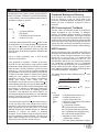
FX Attempted > µFZ
(eq. 1)
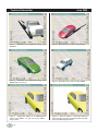
Figure 1 (see Page 4) shows skidmarks from a
straight-line braking simulation using EDSMAC4.
3-D simulations that employ a spin degree of freedom
at each wheel can compare the current longitudinal tire
slip with the characteristics of the tire’s mu-slip curve
(refer to Figure 1 in the December 2001 Technical
Newsletter for a description of a mu-slip curve). A tire
begins to skid when the current tire slip exceeds the slip
at µp.
Steering Without Braking
It is not so simple to determine the point at which a
steered tire begins to skid (technically, when the tire
has a slip angle the term is scuff, not skid). Whereas
skidding from heavy braking tends to occur quickly and
predictably (see above), lateral tire scuffing tends to
occur gradually; there exists no simple mechanism that
leads to tire scuffing. The most common criteria used to
determine the presence of a tire scuff is
non-dimensional sideslip, α. This parameter is