1
Operating instructions | broncolor scoro E | S
Before use
We are pleased you have chosen a broncolor Scoro power pack which is a high-quality product in every
respect. If used properly, it will render you many years of good service. Please read all the information
contained in these operating instructions carefully. They contain important details on the use, safety
and maintenance of the appliance. Keep these operating instructions in a safe place and pass them on
to further users if necessary.
Observe the safety instructions.
ContentsPage
Important safety instructions
6
1. Start up
9
2. LCD display and menu system
10
3. Energy control
12
4. Lamp outlets
13
5. Modelling light
14
6. Release
16
7. Remote control
17
8. Displays visual/audible
18
9. Special functions
19
10. Protective facilities 21
11. Lamp compatibility
21
12. Service/repair
21
13. Additional functions and their listing in LCD main menu Scoro S
22
14. Additional functions and their listing in LCD main menu Scoro E
26
15. Technical data Scoro S
30
16. Technical data Scoro E
32
17. Environmental protection information
34
18. Guarantee
34
Important safety instructions
broncolor flash light systems should be utilised exclusively for professional photo shootings by
qualified personnel. Before starting up your flash light equipment carefully read all the information in your operating instructions. The safety instructions in the operating instructions must be
strictly followed!
>
Read and understand all instructions before using!
>
Remove the transport protection and the packing material!
>Close
supervision is necessary when any appliance is used near children. Do not leave the flash
light appliance unattended while in use!
>Flash light contains, similar to sunlight, a specific portion of UV radiation! The undesirable side ef-
fects on skin and eyes are considerably reduced by using flash tubes or protecting glasses with UV
safety measures! Nevertheless, taking pictures at close distances with unprotected skin and eyes
should be avoided! Also avoid eye contact with the light source! The maximum daily UV radiation
according to IEC 60335-2-27 / DIN 5031-10 is: 50 J/m2. This value should not be exceeded!
>With due allowance for heat radiation, the distance between the lamp and a person or between the
lamp and inflammable or heat sensitive surfaces should be at a minimum distance of 1 m!
>The
power pack must be switched off to plug-in and to unplug! The lamp plugs and sockets have
mechanical interlocks! When plugging in, ensure that those interlocks engage completely! To
unplug, push down the locking spring below the cable guide and lift out the plug from the socket!
>Prior
to replacing flash tubes, halogen lamps, protecting glasses or fuses, disconnect the power
pack and the lamp from the power supply! Prior to replacing the halogen lamp or the flash tube,
the lamp should cool down for 10 min.!
>broncolor flash light systems should only be equipped with original broncolor flash tubes, original
broncolor combustible and packing material, original broncolor accessories, and also original
broncolor spare parts!
>broncolor
power packs, lamps and accessories meet an extremely high safety standard! When
connecting broncolor lamps to power packs of other brands or broncolor power packs to lamp
bases or accessories of other brands, integrated safety measures may become ineffective! Due
to different design features and contact assignment of the lamp plugs of other brands, the user
himself/herself may even be at risk. We offer no guarantee and accept no liability for damages
which may be caused by this type of usage!
>Only
lamps which are approved for operation with this power pack should be utilised!
>Only
earthed extension cables which are approved for operation with the corresponding lamp
should be utilised!
>To avoid the risk of fire, electric shock or injury to persons utilise exclusively the accessory recom-
mended by the manufacturer!
>Check
>The
that the mains voltage corresponds to the information on the type plate of the unit!
flash light equipment is designed for use in dry conditions and in an ambient temperature
from 0°C to 35°C! The flash light equipment has to be protected from wetness, condensation,
from dripping and splash water, humidity, dirt, sand, metal chips and exposure to dust!
6
>Protect
the flash light equipment from electromagnetic fields, shock and vibration!
>Protect
the flash light equipment from heat and frost! If the power pack freezes continuous
loss of power output and serious technical damage can result!
>Sudden
temperature differences can cause condensation water in the unit! In such situations
the equipment must stay for 1 hour in a well ventilated place to acclimatise to the new temperature before start up!
>Do
not operate the units in an environment where there is a risk of explosion!
>The
power pack should not be operated in or near water! Attention: high voltage!
>
The
power pack and the lamps should not be immersed in water or other liquids!
It could cause an electric shock!
>Remove
the transport protection cap on the front side of the lamp before connecting it to the
power pack!
>For
safety reasons, never operate the lamp base without the protecting glass in place! UVcoated protecting glasses or UV-coated flash tubes must be utilised as a protection against UV
radiation for eyes and skin!
>
Before
operation the lamp has to be fastened on a stand or a suspension device!
The lamp must be locked by tightening the mounting screw!
>Only
sand-filled fuses of the type indicated on the safety type plate may be used! Sand-filled
fuses can be identified by their opaque fuse body! With incorrect fuse protection the halogen
lamp may burst!
>Filters
or diffusers should not be fastened directly on the flash tube, halogen modelling lamp
or protecting glass!
>Do not operate appliance with a damaged earthed cable. Cables which are damaged or twisted
must be replaced!
>The
unit must only be connected to an earthed socket, or an emergency power generator!
>If
an extension cable is necessary, a cable with a current rating at least equal to that of the
appliance should be used. Cables rated for less amperage than the appliance may overheat.
When using a cable reel, it must be completely unrolled before use to prevent overheating of
the cable!
>The
unit is suitable for operation with a motor generator provided that the voltage lies within
all the load conditions (including capacitive load) and within the tolerance limit of 200-264 V
or 95-135 V! From experience this means that only electronic stabilised motor generators are
to be utilised! When operating on unstabilised motor generators, voltage peaks of 300 V and
more have been observed! This can lead to damages for which we assume no liability!
>Do
not operate the lamps inside a bag or a box!
>The
ventilation slots on the unit or on the lamp should not be covered!
>Pay
attention when laying, clearing away or rolling up cables that they do not contact hot surfaces or parts of lamps and that they will not be tripped over by persons!
7
Important safety instructions
>Do not touch the connection socket for mains cable and lamp outlets on the power pack and do not
poke in them with metal objects!
>Flash
tubes, halogen modelling lamps and protecting glasses heat up to a high operating temperature, this also applies to the front side of the lamps! Therefore the attachments also assume
high temperatures! Handle with care! Contact with hot components can cause injuries!
>Do
not come into contact with glass or metal whilst operating the flash light system!
>Let
the unit and its connected lamp base cool completely after use and before packing!
>Always unplug appliance from electrical socket before cleaning and servicing and when not in use!
Never jerk cable to pull the plug from the socket. Grasp plug and pull to disconnect!
>Dropped
or damaged units or lamps must be checked by a specialist before reconnection!
>
To
reduce the risk of electric shock, never open the power pack or lamps! Dangerous voltages could still remain inside the unit even after it has been disconnected from the mains supply.
Therefore, take the unit to an authorised broncolor service station when service or repair work is
required. Incorrect reassembly can cause electric shock, even when the unit is closed.
Shipping instructions Scoro:
original broncolor packing for the transport of the power pack!
>Use
Shipping instructions lamps:
>Use original broncolor packing for the transport of the lamps. Before shipping flash tubes, halogen lamp and protection glass pack them with our protective packing material (foam plastic and
transport cap). If the protective packaging is incomplete, remove flash tube, halogen lamp and
protection glass from the lamp and send them separately!
8
We thank you very much that you have chosen a "Scoro" power pack which is a high-quality product in every respect. If used properly, it will render you many years of good service.
Please read all the informations contained in these operating constructions carefully and keep the
manual in a safe place for all users to retrieve the best from the power packs.
1. Start up
2.1Mains voltage
As a standard feature, all the Scoro power packs are supplied as multi-voltage units.
The Scoro power packs automatically adapt to the respective mains voltage.
Scoro power packs deliver for all operating voltages (85-240 V) constant 1600 J or 3200 J.
Attention: Ensure that the operating voltage of the modelling lamp corresponds to the local
mains supply (max. 650 W on 200-240 V or 300 W on 100-120V).
2.2 Earthed mains (AC-line)
Always connect unit to current supply always using an earthed mains plug.
2.3 Start up
Use the mains (AC-line) switch (1) to power up the unit. During the charging process, the digital
master power display (12) flashes, after which, it becomes continuous (see section 11, "Lamp
compatibility").
9
2. LCD display and menu system
The LCD display presents an absolute innovation. It has never been so easy to activate that many
settings with so few keys. The display is a significant tool, and therefore it is important that, firstly,
you become well acquainted with the structure of the menu system.
The brightness of the user interface can be automatically or manually* dimmed dependent on the
ambient light. See LCD setting function "Brightness display" (section 13.20).
2.1 LCD display menu system
Directly after switching on the unit a start display appears for approximately 5 s with information
about the unit and the owner. Afterwards the unit changes automatically to the normal operating mode. By default, the flash duration (t 0.1) is shown permanently. In addition, depending on
whether the flash duration or the colour temperature have been altered*, the display will adjust
and the current value will be indicated.
Scoro E shows additionally the performance in Joules of the connected lamp heads.
When delay (dly), sequence (seq), interval (int), alternate (alt) are activated as well as the studio
and unit address (if desired), the corresponding functions will be shown on the main page. The
functions shown in the display give an overview of the most important activated additional functions of the power pack*.
The main menu is called up with the key "menu" (22). At the same time, at the bottom edge of the
display, a user guide appears, showing the selection keys (21 & 22) each with their supplementary
functions ("q/p", "+/-", "select", "cancel", "quit", "help"). To return to normal mode, press the key
"menu" (22). Each set value is displayed in a box at the top of the LCD.
10
* Scoro S only
The desired unit functions are selected with the keys "q/p" and confirmed with the key "select".
The selected function is visually highlighted with a bar.
After selecting the desired function, one reaches the second level. There, the options are visible
within the chosen function, which can then be selected with the keys "q/p", or "-/+". The previously stored setting is always indicated in a box at the top line. The function on which the cursor
is currently positioned is marked with a bar. The new setting will only be set after the "select"
key has been pressed again. The key "quit" or menu (22) leads back to the respective higher level.
Therefore, it is also possible to quit the submenu without storing a new setting.
2.2Auxiliary function
The key "help" activates an info-text for the respective setting. A practical short description of the
addressed functions is stored there. To return to the main menu press the key "menu" (22).
11
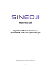
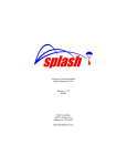
3. Energy control
Use the "q/p" keys (9.1,9.2,9.3*) to control the
flash energy (flash intensity) on each individual
outlet (1, 2 & 3*) within the respective range of
f-stops. The entire energy, however, cannot exceed 1600 J respectively 3200 J. A value of 10 in
the digital master power display (12) indicates
maximum intensity, 1.0 respectively 0.1 minimum intensity (3 joules).
Whole numbers are full f-stops, decimals indicate 1/10 of a whole f-stop. Brief pressure on
the keys "q/p" (9.1, 9.2, 9.3*, 10) runs the power
up (or down) by a 1/10 f-stop level, prolonged
pressure by a full f-stop. The digital display (12)
then blinks until charging or discharging has
reached the newly selected level and the "test"
key light (16) goes out. An acoustic signal announces that the new energy level has been
achieved.
Overview Power Range of Scoro E und S
3200 S
12
1600 S
3200 E
1600 E
Energy
f-stop
Energy
f-stop
Energy
f-stop
Energy
f-stop
3200 J
10
1600 J
10
3200 J
10
1600 J
10
1600 J
9
800 J
9
1600 J
9
800 J
9
800 J
8
400 J
8
800 J
8
400 J
8
400 J
7
200 J
7
400 J
7
200 J
7
200 J
6
100 J
6
200 J
6
100 J
6
100 J
5
50 J
5
100 J
5
50 J
5
50 J
4
25 J
4
50 J
4
25 J
4
25 J
3
12 J
3
25 J
3
12 J
3
12 J
2
6J
2
12 J
2
6J
1
3J
1
3J
0.1
* Scoro S only
3.1 Individual energy distribution (asymmetry) & flash cut-off
Scoro power packs incorporate an electronic flash cut-off system for all 3 channels. The units
have two respectively three individual lamp outlets which can be controlled, with neutral colour
(Enhanced Colour Temperature Control) over the whole range, and with asymmetry up to 6 f-stop
intervals and independently of each other. The unit allows power selection in 1/10 and whole fstop intervals.
3.2Colour temperature control / Asymmetry (in case flash duration t 0.1 is optimal)*
All Scoro S units are equipped with an enhanced ECTC-process which ensures that no colour
temperature shifts or double exposure can occur during individual power distribution. On partial
power, the colour temperature of the set energy can be influenced by relative shifts in intervals of
200 K upwards or downwards (see section 13.5, "Colour temperature"). The control range of the
colour temperature adjustment is increased when on reduced power.
Due to the direct dependence of colour temperature and flash duration, t 0.1 is automatically
adjusted.
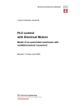
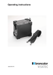
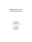
4. Lamp outlets
The lamp outlets of the Scoro units are marked
with the numerals 1 – 2 respectively 1 – 3. Lamp
plugs and sockets have a mechanical locking
device to prevent them from accidentally coming loose. When plugging in, ensure that the
front part of the plug is inserted first, and after
that the rear locking device locks completely
into place. To release, press down the locking
device spring under the cable guide and lift out
the plug from the socket. The power pack must
be switched off whilst plugging in and unplugging.
Each outlet may be switched individually (7.1, 7.2, 7.3*). The digital power distribution displays (11)
indicate the set energy of each individual lamp. The digital master power display (12) indicates the
total energy control range of all the connected or activated lamps.
In addition Scoro E shows the energy performance in Joules per connected lamp head.
It is unnecessary to disconnect a lamp when not in use, simply deactivate it by using the lamp outlet on/off switch. Energy can be asymmetrically allocated to the individual lamps until the maximum energy has been achieved. If an additional lamp is connected, and should the other lamps
already be using the maximum energy, no more energy can be allocated to the newly connected
lamp. By reducing the already set total energy, additional energy can be allocated to a further lamp.
* Scoro S only
13
4. Lamp outlets
4.1Meaning of the digital displays (11)
Example with energy level "8.7":
"8.7" blinks
"—"
> " "
> "-o"
>
>
flash monitor has detected a misfire
lamp connected but switched off
no lamp connected
no energy allocation possible
(the entire energy has already been used up by other lamps)
5. Modelling light
The "mod" key (15) switches on the modelling lamp for all connected lamps. When switched on,
the blue LED next to the "mod" key lights up. The lamps have also an additional modelling lamp
switch. Furthermore, it is possible to operate the modelling light proportionally (section 6.1) and
adapt it to the various maximum outputs of broncolor power packs.
Pressing the "mod" key (15) (for 1 s) when the modelling lamp is on, will give direct access to the
"full" mode. To return to the previous mode briefly press "mod" again.
Attention: Please ensure that the modelling lamp voltage corresponds with the local mains
(AC-line) voltage.
5.1Proportionality
The modelling light brightness can be set proportionally to the flash intensity.
Stages prop1, prop2, prop3, prop4 and prop5 are used to adapt the modelling light brightness of
power packs with different output. The setting "modelling light proportional" duly allows for the
output set, the number of lamps as well as a possible asymmetrical energy distribution of the
Scoro power packs.
Proportionality is guaranteed if the identical operating mode has been set for all power packs. The
higher the digit, the brighter the modelling light.
14
The following operating modes are possible:
"propmax" When working with only a single power pack (in asymmetrical operation); using
the setting "propmax", the modelling light of the lamp with the highest flash energy operates at full output, and the other lamps will be proportionally dimmed,
in accordance with their power settings.
"full"All lamps with full modelling light, independent of flash output, type of power
pack and output distribution.
"low"Lighting level reduced for all lamps to reduce power consumption and extend the
service life of the halogen lamps.
"prop1-prop5"
These levels allow adapting the Scoro units to the proportionality of other
broncolor power packs.
Note: If a power pack is used with less power, it is known that the halogen modelling
light is relatively weak and yellowish. To solve this problem, all broncolor power
packs may be operated with higher modelling light proportionality.
Attention: The Scoro software automatically indicates in the LCD selection text the possible proportionality levels, and warns of sudden altered power settings made by the user.
Important: The modelling lights of all the connected lamps are proportional when all the power packs (independent of their output) have the same proportionality level. This only applies
when all the modelling lights have the same wattage.
5.2 Reduced modelling light
To avoid overloading the mains supply (AC-line), the 100 - 120 V versions of the power packs reduce the modelling light intensity during charging. You can clear this factory-installed feature if
the power rating of the mains supply (AC-line) is sufficient - see setting possibilities of the dimmer
in section 13.11. When working on poor-quality mains supplies (AC-line) you can also slow down
the charging rate with the additional function "charge time" – this reduces the risk of blowing the
supply fuses (section 13.10).¨
During fast charging of Scoro, the modelling light is dimmed, with the exception of the lamp with
the highest power, to avoid overloading the mains supply, even when no reduction / dimmer was
set (section 13.11).
5.3 Modelling light switch on the lamp
The switch on the lamp is used to switch the modelling light on and off. To avoid damage to the
lamp filament, always switch off the modelling light before moving the lamp.
15
6. Release
6.1 RFS / RFS 2 Interface (Radio Frequency System)
Scoro power packs are supplied with built in RFS as well as RFS 2 radio release. The antenna is not
visible as it is integrated into the handle. RFS / RFS 2 can be switched on or off with the key "ir/rf"
(14). A flash release is activated via RFS / RFS 2 and IR by default. The definition of the IR/RFS key
is entered in the LCD display under the position "Flash control" (section 13.12). The following settings are possible: IR/-, -/RFS, IR/RFS. Switching off the RFS / RFS 2, simultaneously deactivates
all the RFS / RFS 2 functions from the camera transmitter. However, the computer connection with
RFS / RFS 2 is maintained.
For flash triggering via RFS / RFS 2, the channel (studio address) must correspond with the channel of the RFS / RFS 2 transmitter. The definition of the channel (studio address) is entered in the
LCD display under the position "studio address" (section 13.14). If the power pack is triggered via
RFS / RFS 2, flash triggering follows with a minimal time delay of approximately 0.8 (0.4) msec.
If RFS / RFS 2 is used only for flash triggering (but not for remote control), the unit address is irrelevant.
6.2 "test" key
This key (16) allows manual release of the power pack. Flash release is possible as soon as 70 %
of the set energy is available.
The visual ready signal (16) however, lights up only when 100 % is available.
6.3Photocell (cell)
The photocell can be switched on or off using the "cell" key (13). If it is activated, the blue LED next
to the key lights up. After the first flash of a sequence, the active photocell will be deactivated and
the blue info-LED next to the "cell" key (13) blinks. By pressing the "cell" key it is reactivated.
6.4 Sync socket
The synchronous cables art. no. 34.111.00 and 34.112.00 may be plugged into the sync socket (4)
to trigger flashes via cable.
6.5 Flash triggering via infrared receiver (ir)*
The IR receiver can be switched on or off with the key "ir/rf" (14). If the function is activated, the
blue LED next to the key lights up. A flash release is activated via RFS and IR by default. The
definition of the IR/RF key is entered in the LCD display under "Flash control"(section 13.12). The
following settings are possible: IR/-, -/RFS, IR/RFS.
Scoro power packs may be triggered by broncolor infrared transmitters. If the power pack is triggered via infrared, the flash release follows with a minimal time delay of approximately 0.8 msec.
6.6Servor*
All broncolor infrared remote controls (servor) can cause inadvertent flash triggering. In this case,
switch off the "IR" function (see section 13.12).
16
* Scoro S only
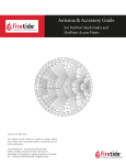
7. Remote control
The remote control system has 20 channels (studio addresses) with up to 20 unit addresses per
channel. The channels assign each an independent workstation. Each flash unit within a workstation is identifiable by its own unit address. Every other workstation can each operate up to 20 flash
units. Therefore, flash units of multiple workstations are clearly identifiable. A PC or Macintosh
computer, or an RFS transmitter can control all the flash units of a studio workstation (channel /
studio address).
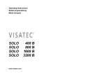
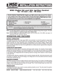
7.1Computer connection with RFS (Radio Frequency System)
The built in interface which allows remote control or flash triggering of the power pack via radio
from RFS transmitter, as well as RFS transceiver from PC or Macintosh computer. Therefore all
the Scoro power pack functions can be comfortably controlled from a digital workstation (see
diagram).
PC / Macintosh screen display
7.2Remote control channels (RFS studio address)
Remote control by means of RFS may be performed via separate channels (studio workstations).
These can be set in the LCD menu under "studio address" (see section 13.14). All flash units within
a studio workstation must have the same channel number (studio address).
7.3RFS unit addresses
Unit addresses will be assigned to each power pack for individual control. (See LCD menu "unit
address", section 13.15).
17
7. Remote control
7.4Computer connection with cable
Scoro units with RFS are equipped with a computer connection socket (3). This allows operation
of the power pack from the computer via cable. Each channel can control up to 20 units. Hence,
Scoro power packs can be remotely controlled by cable with the Bron studio software.
Please note: The RFS and RFS 2 radio frequency systems are not compatible. You can not control units equipped with RFS 2 by the computer.
8. Displays visual | audible
8.1The visual ready signal
This is the blue LED at the "test" key or ready display (16). It lights
up only when the unit is fully charged or discharged. After triggering
a flash, this LED goes out, and lights up again when the unit is fully
charged once more.
The visual ready signal is easy to read even from larger distances. The
brightness (dark / bright) can be altered by the user (see LCD menu
"Brightness test" section 13.17).*
8.2 The audible ready signal
An acoustic signal (beep) sounds when the power capacitors are 100 % charged, or discharged.
The signal may be switched on or off, and the volume may be regulated. The corresponding setting
options are explained in LCD menu "Audio ready signal" (section 13.18).
When Scoro power packs are assigned an individual address, the acoustic signal can be programmed with an individual acoustic (beep) tone.
8.3 Visual fault signal
In case of a technical fault or activation of the flash monitoring, the test
release key/ready signal (16) lights up red. Should the lamp plug not be
correctly engaged, this will be indicated by the red test release key and
the blinking digital display of the corresponding channel (11).
At the end of their service lives, flash tubes often misfire. This fault is
indicated by the test release key of the Scoro power packs that lights
up red. Additionally, the digital display (11) of the channel to which the
lamp concerned is connected, blinks.
Attention: Check to see if the flash tube is in working order, and change if necessary.
18
* Scoro S only
The blinking digital display of the channel concerned can be deactivated by pressing the key "lamp
connection on/off" (7.1, 7.2, 7.3*).
If the fault indication is not caused by the lamp, the power pack must be switched off and on again.
Should the test release key remain red, please contact a broncolor service station.
8.4Audible fault signal
When the flash discharge fails, a warning signal (two-sound tone) of approx. 0.5 s duration will
sound and the display (11) of the relevant lamp will flash.
8.5Audible messages
Clicking tone:
>Key sound (setting of volume is explained in section 13.19).
"Beep" tone:
>End of charging or discharging (setting of volume is explained in section 13.18).
"Double-beep" tone:
>Energy limit top or bottom when controlling energy via RFS / RFS 2 transmitter.
>Reset key pressed for 2 s (resetting of additional functions).
>Reset key pressed for 10 s (reset to factory settings).
"Two-sound" tone:
>Technical fault. Ready signal (16) lights red.
>Flash monitoring. The display of the lamp which has not fired lights up.
>Beginning and end of a thermal blocking procedure. Display in LCD.
>
A suggestion appears on the LCD when setting changes are not possible with the previous
specifications.
9.Special functions
9.1Speed key*
Flash duration t 0.1 and charge time are reduced by pressing the
speed key (17). Therefore, Scoro power packs are optimised for the
shooting of moving objects and / or fast image sequences. As soon
as the speed key is activated, the corresponding LED lights blue and
the maximum flash energy is reduced from 1600 J to 1200 J, and the
energy is reduced from 3200 J to 2400 J. In speed operation, the colour temperature is fractionally colder, however, consistent over the
energy adjustment range.
The display of the maximum output (12) can be adjusted with the function "max. display"
(see section 13.22).
* Scoro S only
19
9.Special functions
9.2User key*
When the user key (18) is "on" it activates the initial settings of a further operator. With this, Scoro
A power packs can be individually configured for two users in which all the relevant functions and
settings are separately stored, thus providing independent preference capabilities for multiple
users.
Those functions, which are stored in standard or user mode, are shown in the two columns "mem"
(memory) and "Standard/User" in chapter 13.
9.3Memory functions*
In standard and user mode, there are each four own memories available. All the unit settings can be stored therein (see LCD function
"memory 1-4" section 13.21). Selecting one of the four memories redirects to an information window in the LCD, in which the most important data of the corresponding memory are indicated. Pressing the
"recall" key reinitializes the data in the memory. Pressing the "store"
key overwrites the memory contents with the latest unit settings.
Those functions, which are stored in standard or user mode, are
shown in the two columns "mem" (memory) and "Standard/User" in
chapter 13.
9.4Alternate release*
This function enables to realise even faster shooting sequences. Alternate release also enables
shorter sequences, four times faster, even with higher energy (see LCD function „Alternate“ section 13.8). With the same function it is possible to reduce the interval of stroboscopic sequences
down to a minimum of 0.01 s (see section 13.6)
9.5Easy mode*
You can minimize the operating display due turn on the easy mode. Please read the following
instructions:
>Press the user key (18) for 5 s. The menu skips to the program setting “easy mode”.
>Activate or deactivate the easy mode by pressing “on” respectively “off”.
>Turn off and turn on the unit. The easy mode is now activated.
9.6Reset key Scoro S
>Brief pressure on the reset key (19) advances the cursor directly to the main page. When pressing
the menu key (22) the cursor returns to the beginning of the main menu.
>Pressing this key for approximately 2 s resets the flash additional functions (see section 13.9). This
is confirmed by a double-beep tone.
>Pressing this key for approximately 10 s resets all the functions to the factory settings. This is
confirmed by a double-beep tone.
9.7Reset Scoro E
Press the test key (16) for 4 s. The unit will reset all the functions to the factory settings.
9.8Submenu Scoro E
To reach the submenu of the Scoro E please press the menu key (22) for 4 s. The correspondent
functions will be more explained in chapter 14.
20
* Scoro S only
10.Protective facilities
10.1 Cooling
The cooling fan switches to a higher speed for a certain time after a few flashes.
10.2 Thermal overheating display
To protect against overheating after extended flash series, the unit will automatically switch off.
At that stage, the following message will appear on the LCD display: "alarm: thermo" and the approximate time required for cooling. The cooling time is shortened if the unit remains connected
and switched on.
10.3Circuit breaker
In the event of an electrical malfunction, the circuit breaker (2) will automatically disconnect the
power pack from the power source. The unit can be restarted by pressing the circuit breaker button. If it disconnects again immediately the power pack must be serviced by an authorised service
station.
11. Lamp compatibility
Almost all broncolor lamps are electrically compatible with the Scoro power packs. The most
popular lamps, such as the Pulso and Unilite range, as well as Ringflash (C & P) may be used with
the Scoro without any limitations.
Particularly for the small lamps, there are thermal limitations which must be taken into consideration when using them with the Scoro power pack (see corresponding max J / min specifications.
on the lamps).
For a detailed compatibility list please visit our website www.broncolor.com -> Downloads ->
Compatibility Charts
12.Service | repair
Your broncolor power pack is a precision device which will work for many years without malfunction if you take proper care of it. If nevertheless malfunctions do arise, please do not attempt to
open the unit to repair it yourself. Even when the unit is switched off, dangerous voltages may
remain within the interior of the device. Therefore, always let our broncolor service station carry
out repairs or service work.
21
13. scoro S
Additional functions & listing in LCD main menu
22
Section
Function
Description of function
13.1
Lamp outlets1-3
Display of the activated lamp outlets in joules or percentage.
13.2
Modelling light
Choice of the modelling light level. See section 5.1.
13.3
Sequence (seq)
Allows to define a flash series or the pre-selection of a defined
number of flashes to be triggered together with the shortest
possible intervals; provided that the "interval" function is not
activated. After the flash series has been triggered, the photocell becomes deactivated. To prevent overheating after extended
flash series (to protect the flash tubes), the unit will automatically shut off.
13.4
t 0.1 (flash duration)
Choice of flash duration t 0.1. The setting range is dependent on
the selected power.
13.5
Colour temperature
Selection of colour temperature adjustment with simultaneous
display of flash duration (see 13.4), on the main page. The setting
range is dependent on the selected power.
13.6
Interval (int)
Allows to define the time between each flash. By briefly pressing
the +/- key, the setting is effected in 0.01 s steps. Prolonged
pressure alters the values in 0.1 - 2 s steps. 50 s are the maximum for intervals.
13.7
Delay (dly)
Delay triggering, this can be delayed in the range of 0.01s – 50.00 s.
13.8
Alternate (alt)
"ping-pong release" of up to 4 power packs. Here, using up to
4 power packs, you can determine the triggering sequence of
these power packs i.e. only one power pack is triggered per
flash trigger signal while the others are waiting, or are being
recharged.This function realises even faster flash sequences.
13.9
Aux. backup
Auxiliary backup stores additional functions (sequence, flash
duration t 0.1, colour temperature, interval, delay and alternate)
when switching off or in case of a power grid cut.
13.10
Charge time
Choice of charging time slow / fast.
"Slow" for longer charging times as option for weak power grids
and motor generators.
part 1
Selection possibility
Default value
Mem
Standard / User
>
joules ("J")
> percentage ("%")
J
√
√
propmax
full
> low
> prop1 – prop5
prop3 for Scoro 1600 E / S
prop2 for Scoro 3200 E / S
√
√
off
√
√
t 0.1 / optimal color temp.
√
√
>
>
>
>
off
+/- (number of flashes per series)
1600 S: 1/265 – 1/10ʼ000 s
3200 S: 1/132 – 1/10ʼ000 s
>
400 K up to + 800 K
optimal color temp.
√
√
>
off
+/- (time between two flashes per
series)
off
√
√
off
+/- (time between trigger signal
and first flash)
off
√
√
number of units (2-4)
sequence (off, active, waiting 1-3)
2
off
√
√
>
>
>
>
>
on / off
off
fast
slow
fast
>
>
√
√
√
23
13. scoro S
Additional functions & listing in LCD main menu
24
Section
Function
Description of function
13.11
Dimmer
The modelling light is reduced (dimmed) during charging. This
option provides protection in case of overloaded power grids or
as a visual flash control.
13.12
Flash control
Selection of flash release: Radio and/or infrared.
13.13
Cell sensitivity
Selection of photocell sensitivity.
13.13
Studio address
To determine studio address or RFS / RFS 2 channel. The same
channel can be set at the bottom of the RFS / RFS 2 transmitter
and in the RFS software.
13.15
Unit address
To determine the unit address / number. Different unit addresses
are possible for each studio address.
With remote control by means of RFS-software each unit must
have a different address.
13.16
Studio display
Studio and unit addresses can be displayed on the main page of
the LCD display.
13.17
Brightness test
Brightness of the test key and visual ready display can be altered.
13.18
Audio ready signal
An acoustic ready signal sounds when the power capacitors are
100 % charged. The volume of the signal can be defined.
With "standard" mode, each unit has the same signal. With
"address" mode, the acoustic signal adapts itself to the unit
number.
13.19
Volume key sound
Setting of volume of acoustic tone when pressing the keys. 4
differents settings are available.
13.20
Brightness display
The brightness intensity of all backlighting LEDs and LCD
displays can be varied. 3 pre-defined settings are available and a
variable function for automatic adjustment to the ambient light.
part 2
Selection possibility
Default value
on / off
> on (100 - 120 V)
> off (200 - 240 V)
Mem
Standard / User
√
√
> IR/RFS (infrared & radio)
IR/RFS
√
high
√
1 – 20
1
√
1 – 20
1
√
> on
off
√
bright
√
> volume: (off, low, medium, high)
> "standard" mode
√
> mode (standard, address)
> medium volume
> off
quiet
√
auto
√
> IR/-- (infrared only)
> --/RFS (radio only)
> low
> high
> off
> dark
> bright
> quiet
> medium
> loud
> high
> medium
> low
> auto
25
13. scoro S
Additional functions & listing in LCD main menu
26
Section
Function
Description of function
13.21
Memory 1-4
Stores and recalls the set unit functions.
The marked positions are stored in the "Mem" column.
13.22
Max. display
Standardization of f-stop display of Scoro S whilst operating with
power packs of different output levels. As max. power Scoro S
indicate number 9.
Further in "speed mode", the power reduction can be calculated
with the power display, this means 9.6 for 2400 J for Scoro 3200
S, or 8.6 for Scoro 1600 S, respectively.
13.23
Flash sequence
Fixed strobo-setting with the fastest possible flash sequence.
This concerns all connected lamps.
13.24
Daily counter
Counts the number of flashes triggered since last reset of daily
counter. A brief pressure on the "reset" key sets the counter
back to 0.
13.25
Flash counter
Counts the number of flashes triggered over the entire lifespan
of the unit. It cannot be reset.
13.26
Serial number
Individual serial number of the unit. Keep available in case of
servicing / repair.
13.27
Program version
Current program version. Can be updated by our service
department.
13.28
Country
Static country code for specific service data.
13.29
Delivery date
Distributors delivery date.
13.30
Language
To simplify operation, you can choose between various languages.
In numeric English the figures of the functions correspond to
the LCD menu of the sub-sections of section 11.
For example: "23 flash sequence" corresponds to the LCD menu
from section 13.23 of the operating instructions
part 3
Selection possibility
Default value
Each with store or recall
Last saved data
√
> maximum output level 9.0 or 10
10
√
(Scoro 1600 S)
> speed max. 9.6 or 10 (Scoro 3200 S),
or. 8.6 or 9.0 (Scoro 1600 S) on max.
output level
> on
Mem
Standard / User
9.6
off
> cancel
> reset
Number of flashes since last
reset of daily counter
none
Number of flashes triggered
since delivery ex factory
none
Serial number
> Scoro
Program versions
> charge
none
Country code
none
Date (mm/yy)
> English
English or distributor setting
√
> German
> Spanish
> French
> Italian
> Swedish
> Chinese
> Japanese
> Korean
> Indonesien
> Numerical / English
27
14. scoro E
Additional functions & listing in LCD main menu
28
Section
Function
Description of function
14.1
Modelling light
Choice of the modelling light level. See section 5.1.
14.2
Sequence (seq)
Allows to define a flash series or the pre-selection of a defined
number of flashes to be triggered together with the shortest
possible intervals; provided that the "interval" function is not
activated. After the flash series has been triggered, the photocell becomes deactivated. To prevent overheating after extended
flash series (to protect the flash tubes), the unit will automatically shut off.
14.3
t 0.1 (flash duration)
Choice of flash duration t 0.1. The setting range is dependent on
the selected power.
14.4
Charge time
Choice of charging time slow / fast.
"Slow" for longer charging times as option for weak power grids
and motor generators.
14.5
Studio address
To determine studio address or RFS / RFS 2 channel. The same
channel can be set at the bottom of the RFS / RFS 2 transmitter
and in the RFS software.
14.6
Unit address
To determine the unit address / number. Different unit addresses
are possible for each studio address.
With remote control by means of RFS-software each unit must
have a different address.
14.7
Audio ready signal
An acoustic ready signal sounds when the power capacitors are
100 % charged. The volume of the signal can be defined.
14.8
Volume key sound
Setting of acoustic tone.
14.9
Serial number
Individual serial number of the unit. Keep available in case of
servicing / repair.
14.10
Program version
Current program version. Can be updated by our service
department.
14.11
Country
Static country code for specific service data.
14.12
Delivery date
Distributors delivery date.
14.13
Language
To simplify operation, you can choose between various languages.
In numeric English the figures of the functions correspond to the
LCD menu of the sub-sections of section 11.
For example: "23 flash sequence" corresponds to the LCD menu
from section 13.23 of the operating instructions
Selection possibility
Default value
propmax
> full
> low
> prop1 – prop5
prop3 for Scoro 1600 E / S
prop2 for Scoro 3200 E / S
√
off
√
t 0.1 / optimal color temp.
√
fast
√
1 – 20
1
√
1 – 20
1
on
off
>
on
√
on
off
>
on
√
>
>
>
off
+/- (number of flashes per series)
1600 E: 1/265 – 1/8ʼ000 s
3200 E: 1/132 – 1/8ʼ000 s
>
>
>
>
>
>
fast
slow
none
>
>
coro
S
charge
main menu
submenu
√
Serial number
√
Program versions
√
none
Country code
√
none
Date (mm/yy)
√
nglish
E
German
> Spanish
> French
> Italian
> Swedish
> Chinese
> Japanese
> Korean
> Indonesien
> Numerical / English
English or distributor setting
√
>
>
29
15. Technical data Scoro s
Scoro S 1600 RFS I 31.041.XX
Scoro S 1600 RFS 2 I 31.044.XX
Scoro S 3200 RFS I 31.043.XX
Scoro S 3200 RFS 2 I 31.045.XX
Normal mode
Normal mode
Flash energy
1600 J
3200 J
f-stop at 2 m , 100 ISO, reflector P70
64 2/10
90 2/10
Flash duration t 0.1 / t 0.5
fastest
max. energy
1/10ʼ000 s / 1/14ʼ000 s
1/265 s / 1/760 s
1/10ʼ000 s / 1/14ʼ000 s
1/132 s / 1/390 s
0.02 - 0.6 s
0.02 - 1.0 s
0.02 - 1.1 s
0.02 - 1.3 s
0.02 - 2.0 s
0.02 - 2.2 s
Charging time
(min.- max. energy)
230 V
120 V
100 V
Switchable to slow charge
Speed mode
Speed mode
Flash energy
1200 J
2400 J
f-stop at 2 m, 100 ISO, reflector P70
45 9/10
64 9/10
Flash duration t 0.1 / t 0.5
fastest
max. energy
1/10ʼ000 s / 1/14ʼ000 s
1/535 s / 1/1ʼ600 s
1/10ʼ000 s / 1/14ʼ000 s
1/285 s / 1/860 s
0.02 - 0.4 s
0.02 - 0.6 s
0.02 - 0.7 s
0.02 - 0.8s
0.02 - 1.2 s
0.02 - 1.4 s
Charging time
speed modus
(min.- max. energy)
30
230 V
120 V
100 V
Ready display
Visual and audible (can be switched off), activated when 100 %
of the selected energy is reached
Lamp outlets
3 outlets with flash cut-off and ECTC
Power distribution
Symmetrical and individually asymmetrical
Control elements
Dust and scratch-resistant, illuminated silicone keypad,
setting by radio remote control
Control range for flash energy
over 9 f-stops
over 10 f-stops
in 1/10 or whole f-stop intervals. LCD display in joules / percentage.
Colour temperature
ECTC technology (Enhanced Colour Temperature Control) for
constant or specifically adjustable colour temperature
Modelling light
Halogen max. 3 x 650 W at 200 - 240 V
Halogen max. 3 x 300 W at 100 - 120 V
Proportional to flash energy, also full and low settings.
Proportionality can be adapted to other broncolor power packs
and to monolights.
Additional functions
t 0.1, sequence, delay, interval, colour temperature, alternating,
stroboscopic, memory and many more
Flash release
Manual release button, photocell, infrared, RFS or RFS 2 receiver
(may be switched off) sync cable, IRX 2
No. of sync sockets
1
1
Computer connection for
remote control (RFS only)
1
1
Stabilised flash voltage
+/- 0.3 %
+/- 0.3 %
16.0 A
15.0 A
15.0 A
16.0 A
15.0 A
15.0 A
Dimensions without handle
28.8 x 19 x 29.5 cm
11.3 x 7.5 x 11.6"
28.8 x 19 x 40 cm
11.3 x 7.5 x 15.7"
Weight
8.9 kg | 19.6 lbs
12.1 kg | 26.7 lbs
Power requirements
230 V
120 V
100 V
31
16 Technical data Scoro E
Scoro E 1600 RFS I 31.060.XX
Scoro E 1600 RFS 2 I 31.062.XX
Scoro E 3200 RFS I 31.061.XX
Scoro E 3200 RFS 2 I 31.063.XX
Flash energy
1600 J
3200 J
f-stop at 2 m , 100 ISO, reflector P70
64 2/10
90 2/10
Flash duration t 0.1 / t 0.5
fastest
max. energy
1/8ʼ000 s / 1/12ʼ000 s
1/265 s / 1/760 s
1/8ʼ000 s / 1/12ʼ000 s
1/132 s / 1/390 s
0.06 - 1.0 s
0.06 - 1.4 s
0.06 - 1.5 s
0.06 - 1.7 s
0.06 - 2.4 s
0.06 - 2.6 s
Charging time
(min.- max. energy)
230 V
120 V
100 V
Switchable to slow charge
Ready display
Visual and audible (can be switched off), activated when 100 %
of the selected energy is reached
Lamp outlets
2 outlets with flash cut-off and ECTC
Power distribution
Symmetrical and individually asymmetrical
Control elements
Dust and scratch-resistant, illuminated silicone keypad,
setting by radio remote control
Control range for flash energy
over 7 f-stops
over 8 f-stops
in 1/10 or whole f-stop intervals. LCD display in joules / percentage.
32
Colour temperature
ECTC technology (Enhanced Colour Temperature Control) for
constant colour temperature
Modelling light
Halogen max. 2 x 650 W at 200 - 240 V
Halogen max. 2 x 300 W at 100 - 120 V
Proportional to flash energy, also full and low settings.
Proportionality can be adapted to other broncolor power packs
and to monolights.
Additional functions
t 0.1, sequence
Flash release
Manual release button, photocell, RFS or RFS 2 receiver
(may be switched off), sync cable
No. of sync sockets
1
1
Computer connection for
remote control (RFS only)
1
1
Stabilised flash voltage
+/- 0.5 %
+/- 0.5 %
16.0 A
15.0 A
15.0 A
16.0 A
15.0 A
15.0 A
Dimensions without handle
28.8 x 19 x 29.5 cm
11.3 x 7.5 x 11,6"
28.8 x 19 x 40 cm
11.3 x 7.5 x 15.7"
Weight
8.7 kg | 19.2 lbs
12 kg | 26.5 lbs
Power requirements
230 V
120 V
100 V
33
17.Environmental protection information
When no longer in use, this product may not be deposited in the normal
household waste but should be brought to a collection point for the recycling
of electrical and electronic appliances.
The materials are recyclable as marked. By re-use, recycling or another
form of using old appliances you are making an important contribution towards the protection of the environment. Please ask your local authorities
for the appropriate disposal point.
18.Guarantee
All broncolor power packs, lamps, monolights and accessories have a high quality standard. We
offer a 2-year factory guarantee from the date of purchase (for the first owner) on the aforementioned units, except for flash tubes, halogen lamps, protecting glasses, cable, batteries, rechargeable batteries and textiles.
Faults resulting from non-observance of safety instructions, incorrect handling, use of accessories of another manufacturer or unauthorised intervention/modification are excluded from the
factory guarantee. We assume no liability for damages resulting from non-observance of the safety instructions, incorrect handling, use of accessories of another manufacturer or unauthorised
intervention/modification.
In case of technical problems please contact immediately the nearest authorised broncolor service station.
Article numbers, product descriptions and scope of delivery can vary from one country to another.
Detailed information are available from your responsible broncolor distributor.
Errors and misprints excepted.
34