1
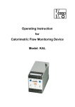
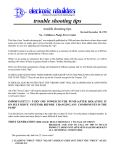
OPERATING INSTRUCTIONS
LEVELING INSTRUMENT
ELECTRONIC LEVEL
USA
Please read the Operating Instructions
before using for the first time
Contents
01
02
03
04
05
06
07
08
09
10
11
12
13
14
15
16
17
18
19
20
Applications and measuring principle
Working range
The parts and their descriptions
Accessories (optional)
Symbols used
Leveling
Notes on handling
Indications for use
Swaying filter (in level measuring mode)
Height calibration / adjustments
Special displays
Renew battery
Notes on aftercare
Observe safety in the workplace
Function check
Malfunctions
Warranty / repair service
Disposal / protection of the environment
Ec declaration of conformity
Technical data
01
APPLICATIONS AND MEASURING PRINCIPLE
The primary applications are taking leveling and control measurement readings in interior
construction work – for other applications please consult the Indications for Use.
Gravimetric measuring is based on the pressure differential that builds up between the
hand-held unit and the fluid reservoir.
02
WORKING RANGE
2.5 m
(4 m*)
2.5 m
(4 m*)
48 m
HORIZONTAL AND
VERTICAL
WORKING RANGE
*) Taking measurements with accessories
03
THE PARTS AND THEIR DESCRIPTIONS
Hose reel
Two handles
Pressure spindle
Indicator light
Hand-held unit with
button and display
Accessories (optional)
04
ACCESSORIES (OPTIONAL)
Consisting of holder for unit, 4 prods, magnetic clamp and
protective cap. The accessories extend the range of vertical measurement. The prods are to be fitted to the top
or bottom depending on the direction of measurement and
should have the magnetic clamp or protective cap attached
at the end.
05
SYMBOLS USED
Press button for a short time
2s
5s
2x
Press button for about 2 seconds
Press button for about 5 seconds
Double click on button
Always turn pressing screw in the direction of »measure« until the noticeable
final position. (Indicator light flashes)
Always turn pressing screw in the direction of »rest« until the noticeable final
position. (Indicator light goes OFF)
Acoustic signal/sound
06
LEVELING
Preparing for leveling
Put the case or reel in a stable position
Reduce the system pressure
Let out enough hose allowing all measuring points to be reached without tension
on the hose reel.
Measuring
Button
Additional functions
Display
Button
Start
Display
5s
Settings
(see Item 10)
Place against reference
point and hold steady
Save the reference level
Check level between
measuring points
Hold
2x
2s
5s
Return to start position
Switch off
Terminating measuring mode
Reel in the hose without twisting it
Put the unit in the case
Pressurize the system
Continue
Vibration filter on
Vibration filter off
07
NOTES ON HANDLING
The selected lead edge on the reference level applies for all further measuring points.
Vertical alignment may be judged by eye.
For aligning in poor light:
In a dark or concealed position, hold displays using
holding:
or after 40 s.
and then read off. To terminate
LED flashing light:
Zero – regular flashing, too low – slow flashing, too high – rapid flashing.
08
INDICATIONS FOR USE
If the following indications are observed, nivcomp allows rapid and reliable level checking.
First check the position of the pressure spindle (see Item 5).
Taking additional measurements for checking based on the reference level
considerably improves measuring reliability.
3m
2m
AROUND
THE HOUSE
OVERCAST
WEATHER
WIND
Inside
buildings
Outside buildings
SUN
1m
0
1
2
3
4
5
6
7
8
± mm
Illustration: Typical measurement reading scatter within hose radius as a function of thermal
conditions and relative measuring height. For this reason no standard deviation is given.
Lay the hose flat and do not let it sag.
When measuring several points, do not do this cumulatively (risk of cumulative
error!), but in a single level-measuring operation.
In the case of a frequently used reference level, provide a permanent lay-on point (nail).
When the °C symbol is displayed, the unit must be allowed to adjust to the ambient
temperature for a few minutes, e.g. after being in transit or at extreme temperatures.
Keep the outline or visual angle.
Do not fling the hose (shock!).
At low temperatures, avoid transmitting warmth from your hands to the hose.
On wet surfaces, only measure with protective interlayer.
Measurements outdoors:
Avoid intense or intermittent sunshine on unit components. A good time for level
measurements outdoors is the early morning.
Do not lay the hose over heated surfaces or expose to major changes in temperature (e.g. on exposed outdoor wall areas).
SWAYING FILTER (IN LEVEL MEASURING MODE)
09
Activate the swaying filter by double clicking 2 x (
symbol). When there is interference from swayings, a more lethargic response is sometimes beneficial. To deactivate
filter:
.
HEIGHT CALIBRATION / ADJUSTMENTS
10
On starting the unit, press the button until
is displayed. The setting options will
now follow each other in slow sequential order. After each operation, press the
button:
Correction of height display by +1 m m / meter for each press of the button.
Correction of height display by -1 mm / meter for each press of the button.
Direction or prefix display arrows or +/–
Height display selection in inches
or millimeters
.
Set all settings to factory settings (Reset).
Height calibration should be checked once a year against a vertical tape measure.
SPECIAL DISPLAYS
Battery has power in reserve for another 20…50 hours.
Warning (flashing) battery discharged (from ~20 hours of reserve power).
Critical temperature change
Measurement range exceeded
1
/2 an hour after a button is pressed an acoustic signal signals switch-off. To
extend time:
.
Hose reel warning hooter activated: Set screw has not been in the »store«
position for a long time!
11
Please note: After 2 hours of continuous operation the indicator light on the pressure
spindle flashes at longer intervals, and after 6 hours it switches into sleep mode
with memory function. To reactivate, turn the pressure spindle into the »store«
position, wait for about 1/2 minute and turn back into the »measure« position.
In case of unknown position of pressing screw, pull rotating head:
mobile = measurement point!
12
RENEW BATTERY
The battery compartment may be opened using a coin
against the head of the hand-held unit. The used battery
must be disposed off in the regional recycling system.
The battery for the indicator light of the pressure spindle must be renewed after about 10
years. For this, completely flush out the hose, turn the pressure spindle into the »measure«
position, loosen 6 screws on the reel casing (do not unscrew the handles) and withdraw
the lower reel section upwards. After changing the battery, ensure that the reel casing
sections click together properly again. Only tighten the 6 screws with light pressure.
13
NOTES ON AFTERCARE
After level measuring, always put the unit back in its case.
Always keep the unit in a clean, dry place once you have cleaned it.
Only use solvent-free cleaning agents.
If the unit is not to be used for a long period set the pressure spindle to the
»store« position.
14
OBSERVE SAFETY IN THE WORKPLACE
Do not run the hose at a height off the floor (trip hazard and risk of catching in
vehicles).
Always top off the accessory prod extension with the protective cap!
Do not use the magnetic clamp above head height!
15
FUNCTION CHECK
Measurement reading stability (temperature-stabilized):
When placed on the reference level for several minutes the deviation should not
exceed 1.
Pressurization:
Put the hand-held unit down and save the position as the reference level. Then
turn the pressure spindle to the limit of the »store« setting. The value displayed
should be in the range 600...1800.
MALFUNCTIONS
16
Unit does not start or suddenly switches off?
Check battery and battery contacts.
Unit switches off with the battery symbol flashin?
Renew the battery.
Indicator light of the pressure spindle does not flash?
See also special displays. Flashing is only weak: Renew the battery.
Increased deviations on taking level measurement readings?
Have you checked the pressure spindle and °C symbol?
Have you followed the notes on »Measuring outdoors«?
Are there airlocks in the hose or sensor area?
Bleeding by our technical service.
Air bubbles can arise if the pressure spindle has been left for several days in the
»measure« position as well as due to overheating or shock.
Damp or condensed water in the case?
If there is damp in the hand-held unit, it must be removed from the battery and
only replaced after being dried. Open the unit and the case and dry them.
Leak in the hose system?
The special hose can withstand high levels of mechanical stress (abrasion and
crushing). If system fluid does leak out (non-poisonous and oily), soak this up
using suitable means and dispose of in line with the regulations relating to waste
oil.
Repair by our technical service.
WARRANTY / REPAIR SERVICE
17
Distribution and service is via reputable specialist dealers. Repairs are performed free of
charge within the warranty period, provided the defect is due to identifiable faults in
material or manufacture.
The unit must be sent to the supplier in a clean condition. A description of the fault or
defect must be included. Current service addresses may be found at
www.dirotec.com
DISPOSAL / PROTECTION OF THE ENVIRONMENT
In line with EU directive 2002/96/EC (WEEE), at the end of its useful life, the user is obliged
to return this leveling instrument to the manufacturer for waste utilization or environmentally
friendly disposal.
18
19
EC DECLARATION OF CONFORMITY
We hereby declare, as the exclusive responsible party, that, on the basis of its design and
construction, the nivcomp electronic hydrostatic level conforms with the relevant basic
health and safety requirements of the EC directives.
Relevant EC directives: EC Directive on Electromagnetic Compatibility/Directive 89 / 336 /
ECC, 92 / 31 / ECC (EN61326 + A1 / A2 / A3, EN61000-6-1, EN61000-6-3 + A11)
Dietzsch & Rothe MSR-Technik OHG
Olzmannstraße 47 / D-08060 Zwickau
www.dirotec.com
20
TECHNICAL DATA
Measuring principle
Reproducibility (indoors, typical)
At maximum measuring point distance
Vertical working range
Height display
Resolution
Approx. temperature range for use
Battery for hand-held unit
Power required/On-time
Automatic switch-off
Flashing indicator
Shock resistance
Transport and storage
Dimensions
Weight
Certification
Low emissions
Analog with digital display
± 2 mm
48 m
± 2.5 m (± 4.0 m)
mm / inch
1 mm (prefixes 0.3 mm)
0 ... +35 °C
1 x AA (alkaline) 1.5 V
~ 10 mW / >
– 250 h
33 min. after pressing a button
3V / Li (Lifetime ~ 10 y)
ca. 1 m impact height
–10 ... + 40 °C / –30 ... +55 °C
450 x 420 x 150 mm
Approx. 5.5 kg
RoHS compliant
In line with EMC product standard
tlt topleveltools
tlt topleveltools
tlt topleveltools
INNOVATIVE pro-GRADE TOOLS
INNOVATIVE pro-GRADE TOOLS
www.topleveltools.com
603-570-4852
tlt topleveltools
ONE NEW HAMPSHIRE AVENUE - SUITE 125, PORTSMOUTH, NH 0380, USA
© by dirotec