1
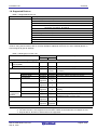
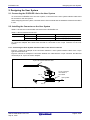
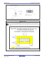
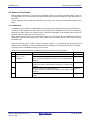
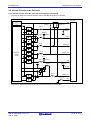
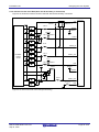
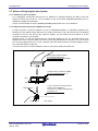
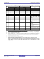
E1/E20/E2 Lite
Contents
Contents
Page
1. Overview ........................................................................................................................................................ 6
1.1. Overview of E1/E20 Emulator and E2 Emulator Lite .......................................................................... 6
1.2. Note on Using E20 .............................................................................................................................. 6
1.3. Configuration of E1/E20/E2 Lite Manuals ........................................................................................... 7
1.4. Supported Devices .............................................................................................................................. 8
2. Designing the User System ........................................................................................................................... 9
2.1. Connecting the E1/E20/E2 Lite to the User System ........................................................................... 9
2.2. Installing the Connector on the User System ...................................................................................... 9
2.2.1. Connecting the User System Interface Cable to the 14-Pin Connector ..................................................... 9
2.3. Pin Assignments of the Connector on the User System .................................................................... 11
2.3.1. 14-Pin Connector Specifications.............................................................................................................. 11
2.4. Recommended Circuit between the Connector and the MCU .......................................................... 13
2.4.1. Connection between the 14-Pin Connector and the RL78 Family MCUs
(Except for the 20-Pin and 24-Pin Versions of the RL78/G12). ......................................................................... 13
2.4.2. Connection between the 14-Pin Connector and the RL78 Family MCUs
(Only the 20-Pin and 24-Pin Versions of the RL78/G12). .................................................................................. 14
2.5. Notes on Connection ......................................................................................................................... 15
2.5.1. RESET# Pin ............................................................................................................................................ 15
2.5.2. TOOL0 Pin............................................................................................................................................... 17
2.5.3. GND ........................................................................................................................................................ 18
2.5.4. VDD ......................................................................................................................................................... 18
2.6. Internal Circuits of the Emulator ........................................................................................................ 19
2.6.1. Internal Circuits of the E1 (when the RL78 Family is Connected) ........................................................... 19
2.6.2. Internal Circuits of the E20 (when the RL78 Family is Connected) ......................................................... 20
2.6.3. Internal Circuits of the E2 Lite (when the RL78 Family is Connected) ..................................................... 21
2.7. Notes on Designing the User System ............................................................................................... 22
2.7.1. Isolators for the E1 and E20 .................................................................................................................... 22
2.7.2. Small Connector Conversion Adapter for the E1 ..................................................................................... 22
3. Notes on Usage ........................................................................................................................................... 24
3.1. Turning the Power On/Off.................................................................................................................. 24
3.1.1. When a Separate Power Supply is Used for the User System ................................................................ 24
3.1.2. When Power is Supplied to the User System from the Emulator (E1/E2 Lite Only) ................................ 25
3.2. Power Supply Function of the E1/E2 Lite .......................................................................................... 25
3.3. MCU Resources to be Occupied ....................................................................................................... 26
3.3.1. Securing an Area for the Debugging Monitor Program ............................................................................ 27
3.3.2. Securing a Stack Area for Debugging ...................................................................................................... 28
3.3.3. Setting an On-Chip Debugging Option Byte ............................................................................................ 28
3.3.4. Setting a Security ID ................................................................................................................................ 29
3.4. Reset ................................................................................................................................................. 30
3.4.1. Operation after a Reset ........................................................................................................................... 30
3.4.2. SP Value after a Reset ............................................................................................................................ 30
3.5. Flash Memory .................................................................................................................................... 30
3.5.1. Flash Memory Programming by Self-Programming................................................................................. 30
3.5.2. Operation for Voltages and Flash Operation Modes Not Permitting Flash Memory Rewriting................. 31
3.6. GDIDIS .............................................................................................................................................. 31
3.7. RESET# Multiplexed Pin ................................................................................................................... 31
3.8. MCUs that are Used in Debugging ................................................................................................... 32
3.8.1. Usage in Mass-Production ...................................................................................................................... 32
3.8.2. Standalone Operation .............................................................................................................................. 32
3.9. Final Evaluation of the User Program ............................................................................................... 32
3.10. Debug Functions ............................................................................................................................. 33
3.10.1. Step Execution ...................................................................................................................................... 33
3.10.2. [Go to Here] ........................................................................................................................................... 33
R20UT1994EJ0400 Rev.4.00
Sep 16, 2015
Page 3 of 38