1
31DT LCD Screen Lathe Machine Tool
Numerical Control System
Operation & Programming Guide
NANJING WASHING CNC DEVICE CO.,LTD
Nanjing Washing CNC System User’Manual
MENU
Chapter One 31DT System Overview ................................................................................................1
1.1 31DT system indicator...........................................................................................................1
1.1.1 Main specifications .....................................................................................................1
1.1.2 System resource...........................................................................................................1
1.2 Coordinate system provision.................................................................................................1
1.2.1 Movement principles which are relative to stationary work piece .........................1
1.2.2 Standard coordinate system provision ......................................................................2
1.2.3 Provision on machine tool moving component direction.........................................2
1.2.4 Machine tool reference point......................................................................................2
1.2.5 Work piece coordinate system ...................................................................................2
1.2.6 Cutting tool compensation principle when changing cutting tool ..........................3
Chapter Two Programming ................................................................................................................4
2.1 Block format...........................................................................................................................4
2.1.1 Parameter ....................................................................................................................5
2.2 Preparative function (G function) ........................................................................................6
2.2.1 G00-Fast locating .....................................................................................................7
2.2.2 G01-Line interpolation ............................................................................................7
2.2.3 G02—Interpolation of clockwise arc.........................................................................8
2.2.4 G03—Inverse arc interpolation .................................................................................9
2.2.5 G04—Time delay ........................................................................................................9
2.2.6 G09-Feed angle-specified stop.................................................................................9
2.2.7 G20-Sub-program call .............................................................................................9
2.2.8 G22-Sub-program definition .................................................................................10
2.2.9 G24—Completion and returning of sub-program .................................................10
2.2.10 G25-Jump processing........................................................................................... 11
2.2.11 G26-Transition processing (sub-program call in the program)........................ 11
2.2.12 G27—Endless cycle................................................................................................. 11
2.2.13 G30—Magnification and minification cancel.......................................................12
2.2.14 G31-Magnification or minification .....................................................................12
2.2.15 G47-Short line speed auto-transition..................................................................12
2.2.16 G48—Cancel G47. ..................................................................................................12
2.2.17 G53—Cancel zero bias............................................................................................12
2.2.18 G54-Absolute zero bias ........................................................................................12
2.2.19 G55-Increment zero bias......................................................................................13
2.2.20 G56-Current point bias........................................................................................13
2.2.21 G71-Internal (external) diameter cutting compound cycle ..............................14
2.2.22 G72—End surface cutting compound cycle..........................................................15
2.2.23 G73—Sealed contour compound cycle..................................................................16
2.2.24 G74—Returning to reference point (mechanical origin).....................................19
1
Nanjing Washing CNC System User’Manual
2.2.25 G75-Returning to presetting cutter point from reference point.......................19
2.2.26 G76—Returning to processing start point from current position (feed point)..19
2.2.27 G77—Recovering current coordinate system.......................................................20
2.2.28 G81-Excircle (inner circle) fixed cycle................................................................20
2.2.29 G82-End surface fixed cycle ................................................................................22
2.2.30 G85-Threading cycle ............................................................................................24
2.2.31 G86-Metric thread cycle ......................................................................................24
2.2.32 G87-English system thread cycle. .......................................................................27
2.2.33 G90-Programming with absolute value mode ...................................................27
2.2.34 G91-Programming with incremental mode .......................................................27
2.2.35 G92-Setting work piece coordinate system ........................................................27
2.2.36 G96-Constant linear speed cutting .....................................................................28
2.2.37 G97-Cancel constant linear speed cutting ..........................................................28
2.2.38 G98-Cancel feed of each rotation........................................................................28
2.2.39 G99-Setting feed of each rotation........................................................................28
2.3 Subsidiary function (M function) .......................................................................................28
2.3.1 M00-Program pause...............................................................................................29
2.3.2 M01-Condition pause.............................................................................................29
2.3.3 M02-Program completion......................................................................................29
2.3.4 M03-Spindle positive rotation ...............................................................................30
2.3.5 M04-Spindle reversion ...........................................................................................30
2.3.6 M05-Spindle stop....................................................................................................30
2.3.7 M08—Open cooling fluid .........................................................................................31
2.3.8 M09-Close cooling fluid .........................................................................................31
2.3.9 M10-Work piece clamping.....................................................................................31
2.3.10 M11—Work piece loosing.......................................................................................31
2.3.11 M20-Open specified relay ....................................................................................32
2.3.12 M21-Close specified relay ....................................................................................32
2.3.13 M24-Setting cutting tool compensation number ...............................................32
2.3.14 M30-Returning to program header ....................................................................32
2.3.15 M71~M85-M function pulse output....................................................................32
2.3.16 Output interface, programming and relay number comparison table...............32
2.4 F、S、T functions ...............................................................................................................33
2.4.1 F-Feed function.......................................................................................................33
2.4.2 S-Spindle speed control..........................................................................................33
2.4.3 T-Cutting tool function ..........................................................................................34
2.4.4 Axis optional function ...............................................................................................38
2.4.5 Coordinate modification and regulation function..................................................38
Chapter Three System Operation ....................................................................................................39
3.1 Safety, protection and compensation..................................................................................39
3.1.1 Emergency stop .........................................................................................................39
3.1.2 Hard limit ..................................................................................................................39
3.1.3 Soft limit ....................................................................................................................40
3.1.4 Clearance compensation...........................................................................................40
2
Nanjing Washing CNC System User’Manual
3.1.5 Screw thread pitch compensation............................................................................40
3.2 Operating keyboard of numerical control system.............................................................41
3.2.1 Primary function key................................................................................................42
3.2.2 Edit character key. ....................................................................................................42
3.2.3 Coordinate feed and feed parameter setting of manually operating machine tool
.............................................................................................................................................42
3.2.4 Soft definition key F1~ F5 ........................................................................................42
3.2.5 Others.........................................................................................................................42
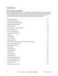
3.3 Starting up ............................................................................................................................44
3.3.1 Starting up, image and design..................................................................................44
3.3.2 Selection of primary function ..................................................................................45
3.3.3 Selection of sub-function ..........................................................................................45
3.4 PRGRM (Program) primary function ...............................................................................46
3.4.1 Input principle of program name ............................................................................46
3.4.2 Program edit..............................................................................................................47
3.4.3 Copy, delete and program status .............................................................................48
3.4.4 Rename, input and output function.........................................................................49
3.4.5 List..............................................................................................................................50
3.5 OPERT (Process) primary function ...................................................................................51
3.5.1 Auto-cycle (including start processing in the position of any block number)......52
3.5.2 Manual operation of machine tool...........................................................................52
3.5.3 Return to machine tool zero.....................................................................................53
3.5.4 Hand wheel (hand-operated impulse generator)....................................................53
3.5.5 System status setup ...................................................................................................54
3.5.6 MDI operating mode ................................................................................................54
3.6 Figure display function........................................................................................................54
3.6.1 Image access sequence of figure display function ..................................................55
3.6.2 Image selection of figure display function ..............................................................55
Chapter Four Parameter function................................................................................................57
4.1 31DT parameter system ......................................................................................................57
4.2 Basic conception of parameter............................................................................................58
4.2.1 Time constant of speed increase and decrease........................................................58
4.2.2 Acceleration ...............................................................................................................58
4.2.3 Electronic gear ratio .................................................................................................58
4.2.4 Parameter password .................................................................................................59
4.3 System parameter (P parameter)........................................................................................59
4.3.1 Meaning of P parameter...........................................................................................60
4.4 Digit Parameter....................................................................................................................63
4.4.1 Access .........................................................................................................................63
4.4.2 Digit parameter setting.............................................................................................63
4.5 Thread pitch error compensation.......................................................................................67
4.5.1 The required caution problems of thread pitch error compensation ...................68
4.5.2 Thread pitch error compensation example.............................................................68
4.6 Spindle ..................................................................................................................................69
3
Nanjing Washing CNC System User’Manual
4.7 Cutting tool parameters ......................................................................................................69
4.8 Coordinate modification and regulation............................................................................70
4.9 Diagnosis (external input signal monitoring) ....................................................................70
4.10 System zero setting.............................................................................................................71
4.10.1 Clear memory..........................................................................................................71
4.10.2 Format .....................................................................................................................71
4.10.3 Password setup........................................................................................................71
4.10.4 Backup .....................................................................................................................72
4.11 Shutdown and starting up .................................................................................................73
Appendix One--Error alarm.............................................................................................................74
Appendix Three Programming Example.........................................................................................76
4
Nanjing Washing CNC System User’Manual
Chapter One 31DT System Overview
1.1 31DT system indicator
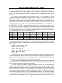
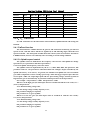
1.1.1 Main specifications
Pulse equivalent
Control/compounding axis number
Programming scope
Foward speed
Program capacity
nterpolation
X:0.001mm Z:0.001mm
2/2
-9999.999~+9999.999mm
60000 mm/min (0.001 mm equivalent)
Electronic disk 128K, which can store 30 programs
Line, arc, metric system, English system straight/cone,
multi-thread/single thread
1.1.2 System resource
Display
Electronic disk
Input signal
Hand wheel interface
Encoder interface
Output signal
Serial port
6″ LCD is adopted with 320X240 dot matrix
128KB memory for saving program status and parameter
24-way on-off and optical isolation
1 way, 1, 10, 100 multiply factor
1 way, four-multiple frequency processing
17-way on-off.. 12-way relay power driving output and 5-way relay
contact output
Stepping motor driving signal (CP and CW) output in X and Z
directions
One-way 8-bit analogue output, 0-5V or 0-10V
RS232C asynchronous serial port
1.2 Coordinate system provision
When the elements are processed on the numerically controlled machine tool, the relative
movement between cutting tool and elements must be in the specified coordinate system, and
then the program can be processed according to provisions. For the convenience of describing
machine tool movement when programming, simplifying the program compilation methods to
guaranty the exchangeability of recorded data, and the coordinate and movement direction of
numerically controlled machine tool have been standardized.. The Ministry of Engineering
Industry promulgated the denomination standards of JB 3051-82 numerically controlled
machine tool coordinate and movement direction in 1982, and the denomination principles and
provisions are as follows:
1.2.1 Movement principles which are relative to stationary work piece
This principle is for programming staves to determine machine tool operating process
according to element drawings under condition that they don't know whether it's the cutting
tool movement or work piece movement..
1
Nanjing Washing CNC System User’Manual
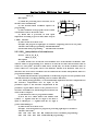
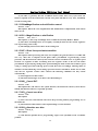
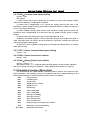
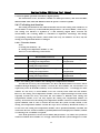
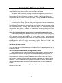
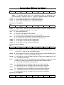
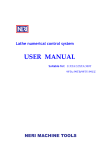
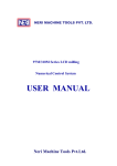
1.2.2 Standard coordinate system
provision
The standard coordinate system is one
rectangular coordinate system. as the figure of
previous page:.
Various coordinate axes of this coordinate
system parallel to primary guide tracks of machine
tool.
卡
+Z
Chuck
盘
+X
Illus 1-1 Standard coordinate system
1.2.3 Provision on machine tool moving component direction
The movement positive direction of certain moving component of machine tool is the one
to increase distance between cutting tool and work piece.
1.2.3.1 Z coordinate movement
The Z coordinate movement is provided by spindle which transmits cutting power. In the
standard coordinate system, the coordinate always paralleling to spindle is provided as Z
coordinate.
1.2.3.2 X coordinate movement
The X coordinate is horizontal, which parallels to clamping surface of work piece. The X
coordinate is the movement primary coordinate in the locating planes of cutting tool or work
piece.
On the lathe, the Z coordinate positive direction is that the big tool carriage moves to end
bracket side along lathe bed (vertical), and X coordinate positive direction is that holder moves
to handgrip direction.
1.2.4 Machine tool reference point
The machine tool reference point is also called mechanical zero, which indicates X and Z
directions to move to the approaching limit position along positive direction, and induces the
determined position of reference point switch in this direction. Whether one machine tool has
reference point returning function depends on whether machine tool manufacturer installs
reference point switch (also called mechanical origin switch).
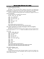
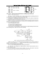
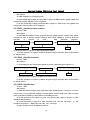
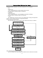
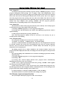
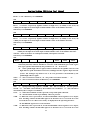
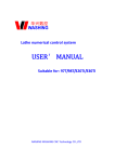
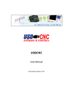
1.2.5 Work piece coordinate system
A
+Z
All the coordinate values are positions
of tool nose relative to coordinate origin. . If
R25
B
the Coordinate origin is different, even if the
刀尖
tool nose is at the same absolute position on
10
the machine tool, its coordinate value is also
100
different. . In order to guaranty uniqueness
250
of tool nose coordinate in processing, the
+X
coordinate origin (also called zero) must be
determined, while zero position is acquired by opposite calculating of tool nose position and
coordinate value..
For instance: If the tool nose coordinate is supposed to be (50, 250), then the 25 mm
position along X negative direction is the X coordinate origin; the 250 mm position along Z
negative direction is the Z coordinate origin (see A position in the right figure)..
Note: On the lathe, the X direction coordinate (also called horizontal direction) is provided
2
Nanjing Washing CNC System User’Manual
as diameter amount..
Now supposing that the tool nose position is unchanged, while the coordinate is (20,100),
then zero is in the B position in the figure, which is the notion of floating zero. However,
towards to one processing program, the processing can be implemented only after determining
zero and optional change is prohibited (unless through instruction of coordinate transition).
Once the floating zero is determined, the work piece coordinate system used in the actual
processing will be composed. All tool nose movements in the program are based on this
coordinate system for reference. . Seeing G92 instruction to determine coordinate zero.
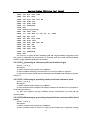
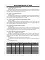
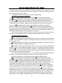
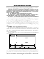
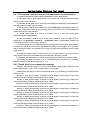
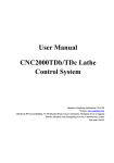
1.2.6 Cutting tool compensation principle when changing cutting tool
When the comparatively complicated work piece is processed, more cutting tools are
frequently required. However, the processing program is compiled according to some one tool
nose of cutting tool. After changing cutting tool, the offset must occur in X and Z directions of
current tool nose relative to previous one. That's to say even if big and small tool carriages
don’t move, the tool nose position will change after changing cutting tool, and the effect of
cutting tool compensation is used to compensate this change.1
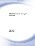
For instance: If current cutting tool is T1, its
tool nose position is A1; after changing for No. 2
Z
cutting tool (T2), the tool nose of it is in the A2
A2(X2,Z2)
position. The tool nose coordinate is changed from
A1 (X1,Z1) to A2 (X2,Z2) after changing cutting
A1(X1,Z1)
tool, and the effect of cutting tool compensation is
to convert the original coordinate (X1,Z1) of tool
X
nose coordinate value to (X2,Z2). The relative
difference in X and Z directions of A1 and A2 can be measured beforehand, and this difference
is the cutting tool compensation value memorized by numerical control system. In practical
applications, in order to simplify this course, the numerical control system doesn't measure
difference of each other among cutting tools, but adopts simpler methods to memorize cutting
tool compensation value.Th That’s the method of memorizing coordinate value for
determination..
For instance: Contacting certain fixed point (core rod or specimen) one by one along X and
Z directions for tool nose of each cutting tool, and this fixed point contacted by tool nose is
regarded as standard. Owing to difference of various cutting tool lengths, the displayed
coordinate point is also different contacting to fixed point. The numerical control system
respectively memorizes coordinate values contacted by various cutting tool. These different
coordinate values of each other actually include the length difference information between the
two cutting tools. Many methods can be utilized to generate cutting tool compensation value,
and 31DT adopts the method that inputting work piece size after one cut, which is equivalent to
regard the presetting cutter as benchmark. It can calculate cutting tool compensation values of
excircle, internal hole and so on, moreover eliminate errors brought about by process system
elastic deformation.
3
Nanjing Washing CNC System User’Manual
Chapter Two Programming
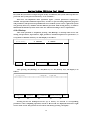
2.1 Block format
The block format means the the wirtten rules of block, it includes the function which will
be implemtented by numerically controlled machine tool and parameters that are required
implementing this function. One part processing program is composed of several blocks, and
each block is composed of various functions; the usual function words which are used by lathe
numerical control system are as follows:.
Function
Program number
Sequence segment
number
Preparatory
function
Address
Scope
P、N
Meaning
Specifying program number and
sub-program number
01~99
N
0000~9999
G
00~99
Program segment number
Instruction movement mode
Movement instruction coordinate,
circle center coordinate, thread
pitch, radius and cycle number
Feed speed instruction
Instruction of spindle rotating
speed
Coordinate letter
X、Z、I、K、
R、L、J、D
±0.001~±9999.999
Feed speed
F
1~60000mm/min
Spindle function
S
0~5000RPM
T
1~8
Cutting tool instruction
M
0~99
Auxiliary instruction
Cutting tool
function
Auxiliary function
The numerical control system doesn't require each block having these instructions above,
however in every block; the instruction should be arried according to certain format.. Each
function word probably has various definitions in different block definitions, refering to
specific instructions..
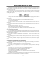
31DT numerical control system adopts the variable block format, which means that the
block length changes with word number and word length.. One block is composed of one or
more program words.. Generally, the program word is composed of address word and
post-address word number and symbol, for instance:
X
-
46.38
Data word (digit)
Symbol (minus)
Address function word
This program word format is composed of address function word as the header following a
string of digits, and several words compose one block. . The words written in the previous block
and unchanged in this block are also valid, which can be no longer rewritten.. In the dimension
words, it can only write valid digit and not specify that every word should write the full
number..
For instance:N0420 G03 X70 Z-40 10 K-20 F100
In the previous segment of program, N、G、X、Z、I、K、F are all address function words
4
Nanjing Washing CNC System User’Manual
N
Block number.
G03
Preparative function, which can be written as G3.
XZIK
Coordinate address.
F
Amount of feed.
“=” “-” Signifying symbol
03 70 -40 0 -20 100 are data words
In the block, the English letters signifying address function can be divided into dimension
word address and non-dimension word. The dimension word address is signified with the
following letters:X、Z、I、K、R、J、D, and non-dimension word address is signified with the
following letters: N、S、T、G、F、M、P、l. All dimensions are signified with diameter or diameter
difference in X direction.. For instance, X50 signifies that tool nose moves to ¤50 position, and
110 signifies that the diameter difference of circle center relative to arc start point is ⊿φ10..
One complete program is composed of program name, block number and corresponding
symbols, please the program below.
N0010 G92 X50 Z100
N0020 S1200 M03
N0030 G01 X40 F300
N0040 Z90
N0050 G02 X30 Z85 I0 K-5
N0060 G01 Z60
N0070 G02 X40 Z55 I10 K0
N0080 G01 X51
N0090 G76 X Z
N0100 M02
In general condition, one block is one process step of element processing, numerical control
program is one block statement sequence which is stored in the memorizer.. When the elements
are processed, these statements are totally read from memorizer and explained into executable
data format and then executed..
The block number is used to identify every block composing program; it's composed of N
with following 0000-9999. The block number must be written at the beginning of every segment,
which can be generated by segment number automatic generater.. (see program edit function)
In one program, the block number can adopt optionlal value in 0000-9999, however in principle,
various block numbers should be arrayed from small to big according to its precedence in the
program.. For the convenience of inserting new block in the required position, it's
recommended not to use continual serial no. to the block when programming, and if the
programming is implemented on the CNC panel, it's suggested that the block be numbered
with interval of 10. In this way, it's easy to assign different block numbers when inserted into
the program.. (parameter 27#)
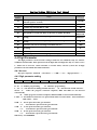
2.1.1 Parameter
The parameters (P0-P9) can be used to substitute digit in the block.. First the assignment
statement in the program can be used for parameter (P0-P9) assignment, and in the subsequent
programs, the assigned parameter can be used to substitute this numerical value. When the
program is automatically excuted, the parameter is changed to the lately assignment number of
this variable.. If this parameter is assigned again in the program, then the new value is only
5
Nanjing Washing CNC System User’Manual
valid to the changed quotation, and the previous quotation still remains the original value..
For instance:
N0010 P2=1 P5=55 P7=200
N0020 GP2 XP5 Z100 FP7
N0030 F2=40 P5=160
N0040 XP2 ZP5
N0050 M02
When the program is executed, it's identical with:
N0020 G1 X55 Z100 F200
N0040 X40 Z160
N0050 M02
2.2 Preparative function (G function)
The preparative function is programmed with G following two digits; it's also called F
instruction, which is used to define geometry and CNC operating status of track.. The functions
of any numerical control device all include fundamental functions and optional functions.. The
fundamental functions are requisite for system, and the optional functions are for user to select
according to machine tool features and applications. It's recommended to program after
understanding the machine specifications first.. The machine tool can configure control
function according to numerical control system, namely the machine tool may not implement
all functions of numerical control system.
The whole G functions of 31DR series numerical control system are as follows:
Modality
G00
Fast locating.
Modality
G01
Line interpolation.
Modality
G02
Clockwise circular interpolation or spiral interpolation
Modality
G03
Anti clockwise circular interpolation or spiral interpolation.
G04
Time delay
G09
Servo angle-specified stop and positioning
G20
Independent sub-program call
G22
Independent of program definition
G24
Independent of program definition completion, and returning to call
program
G25
Skip processing
G26
Block calls processing (sub-program call in the program)
G27
Endless loop
Modality
G30
Multiply factor cancels
Modality
G31
Multiply factor definition
G47
Initiating short line smooth transition function
G48
Cancel short line smooth transition function
G53
Cancel zero bias
G54
Absolute value zero bias
G55
Relative value zero bias
G56
Current point zero bias
G71
Internal (external) diameter cutting compound cycle
6
Nanjing Washing CNC System User’Manual
G72
End surface cutting compound cycle
G73
High speed deep hole processing cycle.
G74
Return to reference point (mechanical origin).
G75
Return to the presetting cutter point.
G76
Return to the program zero from the current position.
G78
Fine boring cycle.
G81
Center hole drilling cycle
G82
Center hole drilling cycle with pause
G85
English system rigidity threading cycle
G86
Boring cycle (auto-return)
G87
Counter boring cycle.
Modality
G90
Absolute value mode programming.
Modality
G91
Increased value mode programming
G92
Setting up program zero
G96
Constant linear speed cutting
G97
Cancel constant linear speed cutting
G98
Cancel feed of each rotation
G99
Setting feed of each rotation
P=
Parameter assignment.
Note: The modality maintains valid after this G function is programmed until superseded
by another modality function of the same quality..
Now, the G functions above will be elaborated.
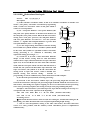
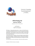
2.2.1 G00-Fast locating
Format:G 00 X _Z _
Description: (1) All the programming axes move simultaneously at the rate which is
defined by 0# parameter, and when certain axle stops after completing programming value,
while other axes move on.
(2) The non-movement coordinate requires no
programming..
(3) The coordinate value of target point can use
absolute value, and can also use increased value. Most 5
digits are allowed before decimal, and after decimal most
3 digits are allowed, the positive number can omit "+"
(this rule is suitable for all coordinate programming).
图 2-1 G00
(4) When G00 is programmed, it's also written as G0.
Example:The right figure program is as follows:
Absolute value mode programming:G00 X75 Z200.
Incremental mode programming:G91 G00 X-25 Z-100
First X and Z move fast simultaneously to A point, then Z. moves 75 fast to B point.
2.2.2 G01-Line interpolation
Format: G01 X_Z_F_
G01 X_F_
7
Nanjing Washing CNC System User’Manual
G01 Z_F_
Description:
(1) When the processing starts each time, it's in
the G01 status automatically.
(2) The non-movement coordinate requires no
programming..
(3) The coordinate of target point can be written
with absolute value or increment value..
(4) When G01 is processed, its feed speed
Illus 2-2 G01
implements according to given F value, and F scope is:
1~6000 mm/min..
(5) G01 can also be written as G1..
Example: The program of right figure is as follows: (supposing tool nose is at A point).
Absolute value mode programming: G01 X40 Z20 F150.
Incremental mode programming:
G91 G01 X10 Z-35 F150
2.2.3 G02—Interpolation of clockwise arc
Format:G02 X_Z_I_K_F_
G02 X_Z_R_F_
Description:
(1) When X and Z are at G90, the end coordinate of arc is the absolute coordinates value
which is relative to programming zero.. When it's at G91, the arc end is the increment value of
relative arc start point.. Towards to G90, G91, I and K, they are all the coordinate values of
center relative arc start point, and I is the diameter amount in X direction value, K is Z
direction. The circle center coordinate can't be omitted at the circular interpolation, unless it's
programmed with R (arc radius).
(2) When G02 instruction is programmed, it can directly program over the quadrant circle
and full circle and so on (R programming can't be used for full circle).
Note: When passing quadrant, . it can automatically implement clearance compensation, if
the clearance compensation isn't be input in the
parameter region, or the clearance compensation in the
parameter region differs much to the practical reverse
clearance of machine tool, which will generate obvious cut
mark on the work piece.
(3) The full circle can't be programmed with R..
(4) R is the arc’s radius which is the number with
symbol, "+" signifies that the arc angle is less than or
Illus 2-3 G03
equal to 180 degree; "-" signifies that the arc angle is
greater than 180 degree..
(5) G02 can also be written as G2.
Example:The AB segment arc program of processing right figure is as follows:
Absolute value mode:
G90 G02 X60 Z30 I20 K0 Fl50(circle center coordinate programming)
G90 G02 X60 Z30 R10 F150(radius R programming)
8
Nanjing Washing CNC System User’Manual
Incremental mode:.
G91 G02 X20 Z-10 I20 K0 Fl50(circle center coordinate programming)
G91 G02 X20 Z-10 R10 F150(radius R programming)
2.2.4 G03—Inverse arc interpolation
Format: G03 X_Z_I_K_F_
G03 X_Z_R_F_
Description: When programming with G03
instruction, except that the arc rotating direction is
opposite, the rest are same as the G02 instruction..
Example: The program of right figure is as follows:.
Absolute value mode:.
G90 G03 X60 Z30 I0 K-10 F100
Illus 2-4 G04
(circle center coordinate programming)
G90 G03 X60 Z30 R10 Fl00(radius R programming)
Incremental mode:.
G91 G03 X20 Z-10 I0 KF100(circle center coordinate programming)
G91 G03 X20 Z-10 R10 F100 (radius R programming)
2.2.5 G04—Time delay
Format: G04 K×××. ××
Description: After the program delays post-K programming value (second), continue to
operate, and the scope of time delay is from 0.01 second to 65.5 seconds.
2.2.6 G09-Feed angle-specified stop
Format:G09
Description: G09 is used to check whether servo is in place, and because servo has
following errors, when it reaches setting error limit, it has some minute time (related with feed
speed). When servo following error is less than given value, servo will send one angle-specified
stop signal (XPSN, YPSN and ZPSN) to CNC system. After the system completes certain
segment program, if this segment has G09, then CNC will check whether various axes have
PSN signal input within a period of time, and this time is set by 89# parameter. If there is no
signal when set time is exceeded, CNC will give 57# alarm to continue operation.
2.2.7 G20-Sub-program call
Format: G20 N ××. ×××
Description:
(1) The first 2-digit after N is the program name of sub-program which will be called and
2-digit is allowed. The 3-digit after decimal signifies the cycle number of this call which can be
from 1 to 255..
(2) The parameter in the sub-program must be assigned definite numerical value by P
when it’s called by G20..
(3) This segment of program mustn't appear contents outside of the descriptions above.
(4) Various sub-programs can repeat embedding call for 10 times, but calling itself is
prohibited.
9
Nanjing Washing CNC System User’Manual
2.2.8 G22-Sub-program definition
Format:G22 N ××
Escription: (1) The sub-program name is initiated with N, and two digits after N is the
sub-program name.
(2) G22 NXX mustn't be in the same segment with other instructions.
(3) G22 and G24 appear in pair, which forms one complete sub-program body.
(4) The parameter data in the sub-program has two kinds of formats:
A) Constant format, the data is constant set by programming, namely 0~9.
B) Parameter format, the numeric section such as function number, parameter and so
on in the program can be signified with variable, while the specific value of variable is imported
by P=×× definition in the main porgram of calling sub-program. This system can process 10
variable parameters: P0 P1 ···P9.
(5) Sub-program and transition processing (G25 and G26) can implement compound
nestification for most 10 times.
(6) When it's necessary for parameter to define variables, P0=××, P1 =×× and so on can
be used to assign definite numerical values to 0#-9#. No matter whether P appears in the main
porgram or sub-program, this parameter will be superseded with the lately assignment.
2.2.9 G24—Completion and returning of sub-program
Format:G24
Description:
(1) G24 signifies completion of program and returns to the next segment of program
calling this sub-program..
(2) G24 and G22 appear in pair..
(3) The segment of G24 disallows other instructions to appear..
Example: The parameter transmission process in the subprogram call will be described
through the following example, please apply it..
Main program P01.
N0010 S1000 M03
N0020 P7=200 P8=50 P9=02
N0030 G20 N05
N0040 M02
Sub-program N05
N0010 G22 N05
N0020 G92 X50 Z100
N0030 G01 X40 FP7
N0040 Z97
N0050 GP9 Z92 X50 I10 K0 FP8
N0060 G01 Z-25 FP7
N0070 G00 X60
N0090 Z100
N0100 G24
Note: (1) If P parameter is not defined when subprogram is called, then the value of P
parameter in the subprogram is indefinite.
(2) The parameter can also be used in the main program.
10
Nanjing Washing CNC System User’Manual
2.2.10 G25-Jump processing.
Format: G25 N××××. ××××. ×××
Description: (1) The cycle body which is defined by this format is the defined block
(including these two segments) between two block numbers following N, and the digit defines
the call number of this block, from 1 to 255, and 1 will be considered without compiling..
(2) The next segment processing program after G25 instruction completes is the one of
jump processing block..
(3) Other instructions are prohibited in the G25 block..
Example:N0010 G92 X50 Z100
N0020 G25 N0040.0060.02
N0030 G00 X10 Z20
N0040 G01 X40 Z80 F300
N0050 Z60
N0060 G00 X50 Z100
N0070 G04 K3
N0080 M02
The processing sequence of program above is:
N0010-N0020-N0040-N0050-N0060-N0040-N0050-N00-N0070-N0080
2.2.11 G26-Transition processing (sub-program call in the program)
Format:G26 N××××. ××××. ×××
Description: The transition processing instruction completes, the next processing section is
the next one of G26 N××××. .××××.. ×××, which is the difference from G25, and the rest are
same as G25.
Example:N0005 S800 M03
N0010 G26 N0050.0080.02
N0020 G04 K2
N0030 G01 X2 F20
N0040 G00 X0 Z0
N0050 G92 G90 X0 Z0
N0060 G01 Z-20 X20 F300
N0070 M00
N0080 Z-40
N0090 Z-60 X0
N0100 M02
The processing sequence of program above is:
N0005-N0010-N0050-N0060-N0070-N0080-N0050-N0060-N0070-N0080
N0020-N0030-N0040-N0050-N0060-N0070-N0080-N0090-N0100
2.2.12 G27—Endless cycle
Format: G27 N××××. ××××
Description:
(1) The block between the first and second block numbers is the interval of endless cycle,
once entering G27 status, the system will infinitely repeat carrying out the operating track
which is defined by this block.
11
Nanjing Washing CNC System User’Manual
(2) In order to guaranty that the coordinate doesn't offset when every cycle starts, the
block is required to be the sealed track, else the start point will shift at every start, and finally
exceeds working table.
2.2.13 G30—Magnification and minification cancel
Format:G30
Description: When the G31 magnification and minification is implemented, G30 cancels
effect of G31.
2.2.14 G31-Magnification or minification
Format: G31 K××. ×
Description: (1) The scope of multiply factor is 0.001-65.5, namely K0.001~K65.5..
(2) The effect of multiply factor is to magnify or minify K times for the various segments'
size of processing track evenly.
(3) The multiply factor has no effect on the cutting tool.
2.2.15 G47-Short line speed auto-transition
Format:G47
Description: When processing non-circle curved plane, the general software of CAD/CAM
uses very short line to impend curved plane under precondition of guarantying certain
precision, and the numerical control system controls various coordinate axes to regulate speed
between two segments of lines. Transiting from one segment of line to the next one under
precondition of guarantying cutting linear speed unchanged, which avoids uneven linear speed
owing to raising speed and reducing speed of each short line, accordingly reducing shake of
machine tool and enhancing actual cutting speed and surface smoothness. When G47 is valid,
only the two segments of lines must conform the following conditions can they transit
automatically:
(1) Line length is less than 21 mm
(2) The intersection angle of two lines is less than 20 degree
2.2.16 G48—Cancel G47.
Format:G48
Description:G47 and G48 are the option function, the numerical control system doesn't
include this function unless it's especially specified.
2.2.17 G53—Cancel zero bias
Format:G53
Description:
(1) After zero bias, G53 function will restore the processing element programming zero to
the initial one.
(2) G53 function will be effective after implementing zero bias function.
2.2.18 G54-Absolute zero bias
Format:G54 X_Z_
Description:
(1) G54 function parallel moves programming origin to the specified X’O’Z’ coordinate
position..
12
Nanjing Washing CNC System User’Manual
(2) The three coordinates of X and Z can all parallel move, it can also for one of
coordinates to parallel move, and the coordinates which aren't compiled don't parallel move..
(3) G54 function is the independent block, and other instructions are prohibited..
(4) The post G54 block will be compiled on the base of G54 established new coordinate
system without considering the original coordinate system effect..
(5) When processing, the dynamical coordinate display is still relative to original
coordinate system origin..
(6) G54 itself is not the movement
15
20
10
20
instruction, it only memorizes coordinate bias.
If it's necessary for cutting tool to operate to
G54, the G01 or G00X0Z0 block must be
compiled once more to make cutting tool
operate to G54.
Ф80
Ф50
Ф60
Ф40
Example:
Z(Z’)
N0010 G92 G90 X40 Z65
N0020 G01 X60 Z45 F100 (AB)
N0030 G54 Z35
N0040 G01 X50 Z0 (BC)
N0050 X80 Z-20 (CD)
N0060 G53
N0070 M02
2.2.19 G55-Increment zero bias
Format:G55 X_Z_
Description:
(1) G55 function will make coordinate system origin parallel move to XZ in increment
from the cutting tool current position, which forms new coordinate system..
(2) Other cautions are same as G54.
Z(Z’)
Example:
Ф20
N0010 G90 G92 X20 Z70
Ф60 Ф50 Ф40
N0020 G01 X40 Z50 F100
N0030 G55 Z-10
N0040 G01 X50 Z0
N0050 X60 Z-20
20
20
10
20
N0060 G53
N0070 M02
X
X’
2.2.20 G56-Current point bias
Format:G56
Description:
(1) G56 function will set the cutting tool current position as the coordinate origin, the
posterior programming will regard this point as coordinate origin without considering the
original coordinate system effect.
(2) The rest is same as G54.
Example:
13
Nanjing Washing CNC System User’Manual
N0010
N0020
N0030
N0040
N0050
N0060
G90 G92 X20 Z60
G01 X40 Z40 F100
G56
G02 Z-20 10 K-10
G53
M02
Ф40
Ф20
20
X
20
Z(Z’)
20
X’
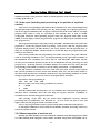
2.2.21 G71-Internal (external) diameter cutting compound cycle
Format: G71 I_K_N_X_Z_F_
Description: The fine machining path of rough machining and fine machining showed in
the instruction execution figure 1 is the track of AÆBÆCÆD..
Among them: I: cutting depth (cutting amount for each time), the symbol isn't added when
specified, and the direction is determined by vector AB:.
K: Retract amount for each time, the symbol isn't added when specified, and the directions
of X and Z are respectively determined by X (X-direction fine machining allowance) and Z (Z
direction rough machining allowance);
N: Fine machining block number;
X: X direction fine machining allowance;.
Z: Z direction fine machining allowance;
F: The F in the G71 programming is valid at the time of rough machining, and the F in the
fine machining block is valid at the time of fine machining.
A
(R)
D
K
45°
(F)
I
C
编程轨迹
X/Z
B
Z
Figure 1 Internal (external) diameter cutting compound cycle G71.
Under G71 cutting cycle, the cutting feed direction parallels to Z axis, and the symbols of
X and Z are showed as Figure 2..(+) signifies movement along axis positive direction, and (-)
signifies movement along axis negative direction..
Note: (1) (fine machining block number) must be greater than 1;
(2) AÆB must be completed by G00 instruction, and the G00 instruction can't be
included within BÆCÆD;.
(3) The Z direction movement amount shouldn't be in the AÆB block, X direction
movement amount is equal to X direction movement total of BÆCÆD.
14
Nanjing Washing CNC System User’Manual
Figure 2 Symbols of X and Z under G71 compound cycle
2.2.22 G72—End surface cutting compound cycle
Format: G72 I_K_N_X_Z_F_
Description: The fine machining path of rough machining and fine machining showed in
the instruction execution figure 3 is the track of AÆBÆCÆD..
Among them: I: cutting depth (cutting amount for each time), the symbol isn't added when
specified, and the direction is determined by vector AB:.
K: Retract amount for each time, the symbol isn't added when specified, and the directions
of X and Z are respectively determined by X (X-direction fine machining allowance) and Z (Z
direction rough machining allowance);.
N: Fine machining block number;.
X: X direction fine machining allowance;.
Z: Z direction fine machining allowance;.
F: The F in the G72 programming is valid at the time of rough machining, and the F in the
fine machining block is valid at the time of fine machining..
Under G72 cutting cycle, the cutting feed direction parallels to X axis, and the symbols of
X and Z are showed as Figure 4.. (+) signifies movement along axis positive direction, and (-)
signifies movement along axis negative direction..
I
D
A
K
Cutting
(F)
Programming
(R)
C
B
X/2
Z
Figure 3 End surface cutting compound cycle G72.
15
tool
Nanjing Washing CNC System User’Manual
Note: (1) N (fine machining block number) must be greater than 1;.
(2) AÆB must be completed by G00 instruction, and the G00 instruction can't be included
within BÆCÆD;.
(3) The X direction movement amount shouldn't be in the AÆB block, Z direction
movement amount is equal to Z direction movement total of BÆCÆD..
Figure 4 The symbols of X and Z under G72 end surface cutting compound cycle
2.2.23 G73—Sealed contour compound cycle
Format: G73 I_K_N_L_X_Z_F
Description: The cutting tool track showed in Figure 5 is the closed loop when this function
is of cutting work, and the cutting tool feeds gradually, which makes the closed cutting loop
gradually approach to the element final shape and finally cut into the shape of work piece, and
its fine machining path is the track of AÆBÆCÆD..
This instruction can implement highly-efficient cutting to the preliminary-finished work
piece in the rough machining such as casting, forging and so on.
Among others:
I: The rough machining total allowance in the X direction;
K: The rough machining total allowance in the Z direction;
N: Fine machining block number;
L: Rough cutting number;
X: X direction fine machining allowance;
Z: Z direction fine machining allowance;.
F: The F in the G73 programming is valid at the time of rough machining, and the F in the
fine machining block is valid at the time of fine machining..
Note: I and K signify the total cutting amount of rough machining, and the rough cutting
number is L, then the cutting amounts in the X and Z directions for each time are I/L and
K/L;.
16
Nanjing Washing CNC System User’Manual
K+Z
(R)
I+X/2
A
(F)
D
C
X/2
B
Z
Figure 5 Sealed contour compound cycle G73.
Appendix: Examples of various compound cycles..
%P55
N0010 G00 X260 Z370
N0020 G71 I7 K2 N8 X.37 Z.29 F2400
N0030 G90 X50 Z370
N0040 G 01 X50 Z350 F240
N0050 G 01 X100 Z230
N0060 G 01 X100 Z170
N0070 G 01 X160 Z170
N0080 G 01 X160 Z100
N0090 G 03 X210 Z50 I0 K-50
N0100 G 02 X260 I50 K0
N0110 G 00 X260 Z370
N0120 G27 N0020.0110
N0130 M02
%P66 Diameter programming
N0010 G 00 X520 Z370 F2400
N0020 G71
I14 K2 N8 X.74 Z.29 F2400
N0030 G00 X100 Z350 F240
N0040 G01 X100 Z350 F240
N0050 G01 X220 Z230
N0060 G01 X200 Z170
N0070 G01 X320 Z170
N0080 G01 X320 Z100
N0090 G03 X420 Z50 I0 K-50
N0100 G02 X520 Z0 I100 K0
N0110 G00 X520 Z370
N0120 G27 N0020.0110
N0130 M02
%P59 Cutting internal diameter
17
Nanjing Washing CNC System User’Manual
N0010
N0020
N0030
N0040
N0050
N0060
N0070
N0080
N0090
N0100
N0110
N0120
N0130
%P77
N0010
N0020
N0030
N0040
N0060
N0070
N0080
N0090
N0095
N0100
N0110
N0120
%P88
N0010
N0020
N0030
N0040
N0050
N0060
N0070
N0080
N0090
N0095
N0100
N0110
N0120
%P99
N0010
N0020
N0030
G00
G71
G00
G02
G03
G01
G01
G01
G01
G01
G00
G27
M02
X10 Z370
17 K2 N8 X-.37 Z.29 F2400
X240 Z370
X190 Z320 I0 K-50 F240
X140 Z270 I-50 K0
X100 Z200
X100 Z150
X60 Z150
X60 Z80
X60 Z80
X10 Z370
N0020.0110
G00 X260 Z370
G72 I7 .K2 N8 X.37 Z.29 F2400
G00 X260 Z40
G01 X160 Z140
G01 X160 Z210
G01 X100 Z210
G01 X100 Z270
G03 X50 Z320 I0
K50
G02 X0 Z370 I-50 K0
G00 X260 Z370
G27 N0020.0100
M02
Diameter programming
G00 X 520 Z370
G72 I7 K2 N8 X.37 Z.29 F2400
G00 X520 Z40
G01 X500 Z90 F240
G01 X320 Z140
G01 X320 Z210
G01 X200 Z210
G01 X200 Z270
G03 X100 Z320 I0 K50
G02 X0 Z370 I-100 K0
G00 X520 Z370
G27 N0020.0100
M02
G00 X270 Z390
G73 I220 K60 N6
G00 X40 Z370
L20 X.6
18
Z.3
F2400
Nanjing Washing CNC System User’Manual
N0040 G01 X40 Z270 F240
N0050 G01 X75 Z140
N0060 G02 X175 Z40 I100 K0
N0070 G00 X200 Z20
N0080 G01 X260 Z390
N0100 G27 N0020.0090
N0110 M02
%P98 Diameter programming
N0010 G00 X540 Z390
N0020 G73 1440 K60 N6 L20 X.6 Z.3 F2400
N0030 G00 X80 Z370
N0040 G01 X80 Z270 F240
N0050 G00 X150 Z140
N0060 G02 X350 Z40 I200 K0
N0070 G01 X40 Z20
N0080 G01 X520 Z00
N0090 G00 X540 Z390
N0100 G27 N0020.0090
N0110 M02
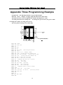
It's necessary to specify the fine machining path and rough machining engagement when
this group of compound cycle instructions are operated, then the system will automatically
calculate rough machining path and cycle number.
2.2.24 G74—Returning to reference point (mechanical origin)
Format:G74 X_Z_
Description:
(1) Other contents in this segment are prohibited..
(2) The coordinates following G74 will return to zero in turn with X, Z sequence..
(3) The reference point switch must be confirmed to be installed on the machine tool before
using G74.
2.2.25 G75-Returning to presetting cutter point from reference point
Format:G75 X_Z_
Description:
(1) Other contents in this segment are prohibited.
(2) After G75 instruction completes, the small coordinates XP and ZP return to position set
by 8# and 9# parameters.
(3) After G75 completes, the big coordinate will be automatically set as 18# and 19#
specified values.
2.2.26 G76—Returning to processing start point from current position (feed
point)
Format:G76 X_Z_
Description:
(1) Other contents in this segment are prohibited..
(2) The coordinate which is relative to origin on the machine tool is displayed with big
19
Nanjing Washing CNC System User’Manual
coordinate, and the coordinate of certain position can be memorized in 18# and 19# parameters.
This function can return to this position from machine tool optional position, and the speed is
same as G00..
(3) The processing start point (18# and 19#) is set referring to processing origin (like chuck
center), and the result of G76 execution is to move tool nose to the same coordinate position
with parameters 18# and 19#.
2.2.27 G77—Recovering current coordinate system
Format G77 X_Z_
G77 X_
G77 Z_
Description: G77 can only be used with G75 to recover work piece coordinate system
before G75 execution.
2.2.28 G81-Excircle (inner circle) fixed cycle
Format: G81 X_Z_R_I_K_F_
Description:
(1) Under absolute coordinates mode, X and Z are absolute coordinates of another end
surface (end point), and under incremental programming mode, X and Z are increment values
of end point which is relative to current position..
(2) R is the processing diameter of start point section..
(3) I is the rough turning feed amount and K is the fine turning feed amount. I and K are
symbolic numbers, and their symbols should be the same. . The symbols are specified as follows:
Cutting from outward central axis (turning excircle) is "-", on the contrary it's "+"..
(4) Various X, Z and R values determine different shapes of excircle such as: with taper or
without taper, positive taper and negative taper, left cutting or right cutting and so on..
(5) F is the feed speed (mm/min) of cutting processing..
(6) After processing completes, the cutting tool stops at the end point.
Example 1: positive taper excircle, the left cutting is implemented.
G90 G81 X40 Z100 R30 I-1 K-0.2 F200(Absolute value programming)
G91 G81 X0 Z-50 R30 I-1 K-0.2 F200(Increment programming)
Processing course:.
① G01 feeds two times of I (the first cutting is I,
and the final cutting is I+K fine turning), implementing
depth cutting;.
② G01 two axes interpolation, cutting to the end
point section, and it will stop if processing completes;.
③ G01 retracts I to safety position, and the
(a) 正向锥度外圆
auxiliary section smoothness processing is implemented
simultaneously..
④ G00 retracts △Z to start point section;.
③ ①
⑤ G00 fast feeds to I position off from work piece
④
②
⑤
surface, and I is preserved to implement the next step
(b) 加工过程图
cutting processing and repeated to ①..
图 2-14
20
Nanjing Washing CNC System User’Manual
Example 2: Non-taper excircle, the left cutting
is implemented.
G90 G81 X30 Z100 R30 I-1 K-0.2 F200
(Absolute value programming)
G91 G81 X-10 Z-50 R30 I-1 K-0.2 F200
(Increment programming)
Example 1 of processing course.
图 2-15 无锥度外圆
Example 3: Negative taper excircle, the left cutting is implemented.
Taking into consideration of cutting amount of end point, the cutting tool should maintain
proper distance (≥△Ф) from work piece at the start point..
G90 G81 X30 Z100 R40 I-1 K-0.2 F200
(Absolute value programming)
G91 G81 X-30 Z-50 R40 I-1 K-0.2 F200 (Increment
programming)
Processing course:
(a)
① G01 feeds two times of I (the first cutting is I, and
the final cutting is I+K fine turning), implementing depth
cutting;.
② G01 two axes interpolation, cutting to the end point
section, and it will stop if processing completes;.
(b)
③ G01 retracts I, and the auxiliary section
图 2-16
smoothness process is implemented simultaneously;.
④ G00 fast retracts △Ф to safety position;.
⑤ G00 fast retracts to start point section and is repeated to ①.
Example 4: Negative taper excircle, the right cutting is
implemented.
Absolute value programming:
G90 G81 X40 Z150 R30 I-1 K-0.2 F200
Increment programming:
G91 G81 X0 Z50 R30 I-1 K-0.2 F200
The processing course is same as example 1.
图 2-17
Example 5: Negative taper inner circle, the left cutting is implemented.
G90 G8l X30 Z100 R40 I l K0.2
F200
(Absolute value programming)
G91 G81 X30 Z-50 R40 I1 K0.2 F200
(Increment programming)
Processing course:.
It's similar to example 1, and the difference is that
图 2-18
the cutting tool retracts to the central axis direction
when retracting.
21
Nanjing Washing CNC System User’Manual
2.2.29 G82-End surface fixed cycle
Format: G82 X_Z_R_I_K_F
Description:
(1) Under absolute coordinates mode, X and Z are absolute coordinates of another end
surface (end point), and under incremental programming
mode, X and Z are increment values of end point which is
relative to current position..
(2) R=(end point diameter—start point diameter),the
end point (start point) diameter is the final cone diameter on
the end point (start point) section. When the flat end surface
cutting short work piece processes, the end-point diameter
and start point diameter are both zero. . R is the symbolic
(a)
number, "+" signifies that end-point diameter is greater than
start point diameter, and "-" is the opposite..
(3) I is the rough turning feed and K is the fine turning
feed. I and K are symbolic numbers, and their symbols should
be the same. The symbols are specified as follows: leftwards
cutting processing is "+" (omission is allowable), and
(b)
rightwards cutting processing is "-"..
(4) Various K, Z, R and I values determine different
shapes of end surface, among them R value determines
whether there is taper, and end surface has no taper when R is
equal to 0; If X=0 and R=0 at the same time under absolute
mode, then the work piece will be cut short and end surface is
turned flat; the symbol of R determines taper direction with
(c)
taper end surface; all symbols of Z, R and I determine the
Illus 2-19
cutting mode of taper end surface, which is divided into
internal cutting and external cutting. . Towards to
programming of various conditions, they will be elaborated on with examples..
(5) F is the feed speed (mm/min) of cutting processing..
(6) Towards to the end surface without taper, the processing length has no limit; but
towards the end surface with taper, the processing length is limited within the one between two
end surfaces, and cutting tool requires stopping on one of two end surfaces before processing
starts. After processing completes, the cutting tool stops at the programming end point..
Example 1: The end surface cycle which taper has steps and the cutting tool can stop at A
or B position and starts from A position at the beginning..
G90 G82 X30 Z100 R10 I—1 K—0.2 F200 (Absolute value mode)
G91 G82 X—10
Z—5 R10 I—1 K—0.2 F200 (Increment mode)
Processing course:.
① G01 and Z direction feed two times of I (the first cutting is I, and the final cutting is I+K
fine turning), G1 and X direction feed to the end point implementing depth cutting;
③ G01 two axes interpolation, cutting to the other end surface; G01 and Z direction
retract I to safety position, and the auxiliary section smoothness process is implemented
simultaneously;
22
Nanjing Washing CNC System User’Manual
⑤ G00 and X direction retract to start point;.
⑥ G00 and Z direction fast feed to I position off from work piece surface, and I is
preserved to implement the next step cutting processing..
⑦ If the processing completes, G01 will feed to end point and stop, else it'll repeated to ①..
Starting from B position.
G90 G82 X20 Z105 R-10 I-1 K-0.2 F200 (Absolute value mode)
G91 G82 X-20 Z5 R-10 I-1 K-0.2 F200 (Increment mode)
Processing course:.
① G00 and Z direction fast feed to A position;.
② G01 and Z direction feed two times of I (the first cutting
is I, and the final cutting is I+K fine turning), implementing
length cutting;.
③ G01 and X direction feed to the end point implementing
depth cutting;.
④ G01 two axes interpolation, cutting to the other end
surface;.
Illus 2-19
⑤ G01 and Z direction retract I to safety position, and the
auxiliary section smoothness processing is implemented
simultaneously..
⑥ If the processing completes, G01 will feed to end point
and stop, else G00 and X direction retract to start point;.
⑦ G00 and Z direction fast feed to I position off from work
piece surface, and I is preserved to implement the next step
cutting processing..
⑧ Repeated to ②..
Illus 2-20
Example2: The end surface cycle which taper has no steps
and the cutting tool can stop at A or B position and starts from A position at the beginning.
G90 G82 X20 Z100 R0 I—1 K—0.2 F200 (Absolute value mode)
G91 G82 X—10 Z—10 R0 I—1 K—0.2 F200 (Increment mode)
Processing course: It's similar to example 1.A, and the difference is without the ③ step..
Starting from B position.
G90 G82 X20 Zll0 R0 I—1 K—0.2 F200 (Absolute value mode)
G91 G82 X—10 Z10 R0 I—1 K—0.2 F200 (Increment mode)
Processing course: It's similar to example 1.B, and the difference is without the ④ step..
Example 3: The end surface cycle which taper has no steps, the cutting tool can stop at A
or B position and starts from A position at the beginning..
G90 G82 X40 Z100 R20 I -1 K -0.2 F200 (Absolute value mode)
G91 G82 X0 Z -5 R20 I -1 K -0.2 F200 (Increment mode)
Processing course: It's similar to example 1.A, and the difference is without the ② step..
Starting from B position.
G90 G82 X20 Z105
R -20 I -1 K-0.2 F200 (Absolute value mode)
G91 G82 X -20 Z5
R -20 I -1 K-0.2 F200 (Increment mode)
Processing course: It's similar to example 1.B, and the difference is without the ③ step..
According to various X and R values, the following figure can also be programmed:
23
Nanjing Washing CNC System User’Manual
(a)
(b)
Illus 2-21
Example 4: The concave end surface cycle with steps. The
cutting tool should stop at the central position when it's
processed from center to outside, which guaranties the cutting
tool not to be bumped at the time of retracting..
G90 G82 X20 Z100 R—10 I—1 K—0.2 F200
(Absolute value mode)
G91 G82 X20 Z—5 R—10 I—1 K—0.2 F200
(Increment mode)
In the examples above, if I and K are changed into "+"
simultaneously, then the figure will regard X-axis as mirror image and right processing will be
implemented.
2.2.30 G85-Threading cycle
31DT standard configuration has no this function
2.2.31 G86-Metric thread cycle
Format:G86
ΔX
Z K
I/D R
N
L J
格式:G86 X Z_ K_ I/D_ R_ N_ L_ J_
Z direction de-trailing length (Plus positive value).
Cycle number
Thread head number, which is used for multiple thread
(N≤150)
The diameter difference between thread outside diameter
and root diameter, which is positive value
The de-trailing length after thread is completed in
X direction/screw in distance value
Thread pitch (metric system Kmm, English system K
teeth/Inch).
Length of thread, it can be absolute or relative
programming
ΔX is the diameter change in X direction, and it's the
straight thread when ΔX is equal to 0.
Description:
(1) The feed depth of each time is determined by P10 and P11assignment statements before
program, and the X direction single side feed smooth thread flat of final cutting.. (smoothing
tool amount is determined by 25# parameter).
(2) The de-trailing direction of thread in X direction is determined by I value, "+" is the
external thread and "-" is the internal thread..
(3) The initial position of thread processing cycle is where the tool nose is aligned with
thread top diameter..
24
Nanjing Washing CNC System User’Manual
(4) J value signifies the preserved de-trailing length in Z direction. . Non-compiling
signifies the system default..
Z
第二刀
第一刀
X
起点
第二刀退尾
第一刀退尾
停刀点
Illus 2-24
(5) When it's necessary to wait for thread pitch ending, the screw out function can be used,
and it's format is to add J value into the general G86 function. The digits after J signifies
de-trailing length in Z direction, namely when the distance between tool nose and thread
end-point is the value after J (Z direction), the de-trailing will be started in X direction. When J
value isn't compiled, the de-trailing will be implemented after Z direction moves to approach
end-point..
(6) Normally the de-trailing length is signified with value after I in X direction of G86,
when D is compiled, it signifies that the thread feed is screw in. Please note when using screw in
function: When feed is started, the tool nose must be in the distance greater than or equal to D
value outside of work piece surface, else the cutting tool will be bumped; the screw in distance
is equal to de-trailing one (X direction)..
(7) According to I, J and D programming, there are four combinations:.
a) G86 Z—100 R2 K3 L10 I5 common thread processing
b) G86 Z—100 R2 K3 L10 I5 J6 de-trail with 6mm from Z direction
end-point
c) G86 Z—100 R2 K3 L10 D5 screw in cut-in but without equal thread pitch
de-trailing
d) G86 Z—100 R2 K3 L10 D5 J6 screw in and screw out
The angles of A and B are different according to various thread processing speed (K× n
rotating speed × thread pitch), screw in and screw out speed in X direction (16# parameter, and
16# parameter ≤59# parameter), screw in and screw out time constant in X direction (49#
parameter) and Z direction time constant (400 parameter) when the thread is processed..
Illus 2-25
25
Nanjing Washing CNC System User’Manual
(8) The 16# parameter signifies the screw in and screw out speed in X direction, and the
general programming value is from 2000 mm/min to 3000 mm /min. However when the set
value is less than 1000 mm/min, it'll be automatically set to 2500 mm/min when system
processes..
(9) Towards to the sub-cutting tool of thread cutting, it can be optionally set in the
program, adopting the assignment statement P10=0, 1 and 2. . a). When P10=0, it's the
equidistance feed at the time of thread cutting, namely the feed amount of each time is R/L,
and when the 25# parameter is not equal to 0, finally increasing one cut of smoothing tool. .b).
When P10=1, it's the equal cutting amount feed. . Towards to 60 degree screwer, the metal
cutting amount of every feed can be guarantied basically identical. . Its formula is: Δ
Rn=( n - n − 1 )×R/ L , ΔRn: Feed amount of the n time. . N: Feed of the n time. . N≤L..
L: Cycle number, R: Total cutting depth. c) When P10=2, it's the equal cutting amount feed,
and the first cut when P10=1 is divided into two cuts for cutting. . If the cutting amount of first
cut is too big, P10 can be set as 2, and system will divide the first cut into two for cutting, to
prevent damaging tool nose such as when R=1.0, L=5:.
P10
The first
cut
The second
cut
The third
cut
The fourth
cut
The fifth
cut
The sixth
cut
The seventh
cut
0
0.2
0.2
0.2
0.2
0.19
0.01..
/
1
0.45
0.19
0.14
0.12
0.09
0.01
/
2
0.23
0.22
0.19
0.14
0.12
0.09
0.01
(10) Towards to the thread cutting mode, it can be optionally set in the program, adopting
the assignment statement P11=0, 1, 2 and 3.. A) When P11=0, it's the normal cutting, b)When
P11=1, it's the left cutting, c) When P11=2, it's the right cutting, d) When P11=3, it's the left and
right cutting..
Example:N0010 P10=2 P11=0
N0020 G00 X100 Z100
N0030 G00 X50 Z1
N0040 G86 Z50 K1 R1 I6 L5
N0050 G00 X100 Z100
N0060 M02
(11) There is the course of speed increase and decrease when the thread processing is
started and completed, and the thread is inaccurate within this period, accordingly these two
regions must be avoided at the time of actual processing. . The 40# parameter defines the
speedup time constant in Z direction when the thread is processed..
(12) The speed of stepping motor/servomotor shouldn't exceed certain value when the
thread is processed, such as 2.5m/min, and this speed is related with machine tool size and
power of motor, which is determined by 45# parameter..
(13) CNC measures the spindle rotating speed before thread is cut, and determines the
optimal course of speed increase and decrease of stepping motor, as well as judges whether
spindle rotating speed is stable, after the zero signal of encoder appears, the processing will be
started, and this course requires 50—100 millisecond. If the spindle rotating speed is not stable,
CNC will start processing after the spindle rotating speed is stable. . If the steady speed isn't
measured, the thread processing won't be implemented in general. 23# parameter signifies
percentage of spindle speed fluctuation, which 10-13 is used in normal, and the spindle rotating
speed fluctuation ratio should be less than or equal to 23# parameter at actual processing.. (14)
26
Nanjing Washing CNC System User’Manual
The 25# parameter sets the smoothing tool amount of the final cut of thread, and if thread
processing cycle requires no smoothing tool finally, the 25# parameter should be equal to 0..
(15) When only G86X-Z-K is compiled, the single-tool thread cutting will be implemented
without retracting after cutting is completed..
Note: At screw in (D value is valid), only straight thread can be processed. . J must be
positive value.
2.2.32 G87-English system thread cycle.
Format: Same as G86..
Note: The thread pitch is K teeth/Inch.
2.2.33 G90-Programming with absolute value mode
Format:G90
Description:
(1) When G90 is compiled into program, the programming zero will be regarded as
benchmark for all the compiled coordinate values afterwards..
(2) After the system is powered on, the machine tool is in the G90 status.
Example:
N0010 G90 G92 X20 Z90 N0020 G01 X40 Z80 F100
N0020 G01 Z60 F50
N0030 G03 X60 Z50 I0 K-10
N0040 M02
2.2.34 G91-Programming with incremental mode
Format:G91
Description: When G91 is compiled, all the coordinate values afterwards will be based on
the previous coordinate position as the start point to calculate movement programming value. .
In the following coordinate system, the previous point will always be regarded as the start point
for programming..
Example:
N0010 G91 G92 X20 Z85
N0020 G01 X20 Z—10 F100
N0030 Z—20
N0040 X20 Z-15 F100
N0050 M02
2.2.35 G92-Setting work piece coordinate system
Illus 2-26
Format:G92 X_Z_
Description:
(1) G92 only changes the current displayed coordinate value of system, and the coordinate
axes require no shift to set coordinate origin..
(2) The effect of G92 is to change the displayed tool nose coordinate into the set value..
(3) The X and Z following G92 can be compiled respectively, and can also be compiled
wholly.
27
Nanjing Washing CNC System User’Manual
2.2.36 G96-Constant linear speed cutting
Format:G96
Description:
(1) The constant linear speed cutting only be suitable for system with analogue output,
which controls infinitely variable speeds of spindle..
(2) When G96 is implemented, CNC regards the cutting speed of this time as the
benchmark, and the spindle rotating speed will be regulated in linear according to whether it's
feed or retracting in X direction..
(3) When spindle rotating speed reaches rated maximal rotating speed of system, the
continuous feed is implemented in X direction, and the spindle rotating speed no longer
changes..
(4) G96 is canceled by instructions such as G97, M05, M02 and so on..
(5) Because the spindle frequency converter has time setting of increase/decrease speed, so
when G96 takes effect, the shorter the increase/decrease speed time constant, the better the
following of spindle rotating speed..
(6) The lower limit of spindle rotating speed is determined by 28# parameter at constant
linear speed cutting.
2.2.37 G97-Cancel constant linear speed cutting
Format:G97
2.2.38 G98-Cancel feed of each rotation
Format:G98
2.2.39 G99-Setting feed of each rotation
Format:G99 F××××××
Description: The F×××××× following G99 is the feed distance of each rotation, which the
unit is Ųm, namely only integer can follow F. . This is different from feed of every minute.
2.3 Subsidiary function (M function)
The M function is also called subsidiary function, which is used for state control of CNC
input and output. . The subsidiary function is composed of M with two digits following it, and
the subsidiary functions of 31DT numerical control system are as follows:.
M00
Program pause
M01
Condition pause
M02
Program end
M03
Spindle positive rotation
M04
Spindle reverse.
M05
Spindle stop.
M08
Open cooling fluid
M09
Close cooling fluid
M10
Work piece clamping
M11
Work piece loosing
M20
Open specified relay
M21
Close specified relay
M24
Setting cutting tool compensation number.
M30
Returning to program beginning
M71~M85
M function pulse output
28
Nanjing Washing CNC System User’Manual
M function is the one to switch on or switch off machine tool external switches such as
spindle startup, stop and refrigeration motor switching on or switching off. . M function is
always different from the one prescribed by standard owing to differences of machine tool
manufacturer and machine tool structure as well as model..
Then M functions will be elaborated on.
2.3.1 M00-Program pause
Format:M00
Description: M00 appears in the program, and pauses after this segment program
completes. . Pressing the processing start key, and the program continues.
2.3.2 M01-Condition pause.
Format:M01 K×× or M01 L××
Description: The two digits after K (or L) is corresponding to certain number of I/O, and
the program will stop here until the exterior inputs one low-valid (or high-valid) signal to the I
/O, then program will continue. The valid time of external level is required greater than 100
milliseconds. . K is high-level valid and L is low-level valid. . The input port number definition
of 31DT system is given below:.
1# input port———1# cutting tool
2# input port———2# cutting tool
3# input port———3# cutting tool
4# input port———4# cutting tool
5# input port———5# cutting tool
6# input port———6# cutting tool
7# input port———7# cutting tool
8# input port———8# cutting tool
9# input port———XREF
10# input port——ZRDY
11# input port——YRDY
12# input port——YPSN
13# input port———XPSN
14# input port———XRDY
15# input port———YREF
16# input port———XERR、YERR、ZERR
17# input port———+ limit
18# input port———ZREF
19# input port———emergency stop
20# input port———start
21# input port———limit
X# input port———H/L
23# input port———emergency stop
24# input port———ZPSN
Among them, 19# input port can only be used for emergency stop.
2.3.3 M02-Program completion.
Format:M02
29
Nanjing Washing CNC System User’Manual
Description:
(1) M02 completes processing program..
(2) If the SLOF digit of digit parameter 00# is equal to 0, M02 will close spindle (M05) and
refrigeration (M09), and this cycle is completed..
(3) If the SLOF digit of digit parameter 00# is equal to 1, M02 won't close spindle and
refrigeration, and only this cycle is completed.
2.3.4 M03-Spindle positive rotation
Format:M03
Description:
(1) The M03 instruction is in the program, first the spindle positive rotation relay will be
switched on, then S function outputs analogue and control spindle to rotate in clockwise
direction.
It
controls
1#
relay.
.
M03
movement
sequence:.
Whether it reverses.
Open positive rotation
Time delay (13# parameter).
Time delay (11# parameter)
End
No
Yes
Close reversion
(2) If 21# parameter is equal to 0, M03 will maintain output.
(3) If 21# parameter is equal to 1, M03 is the pulse output, and pulse delay is determined
by 15# parameter
2.3.5 M04-Spindle reversion
Format:M04
Description:
(1) Controlling 2# relay and starting spindle reversion.. M04 movement sequence is:.
Whether it's positive rotation
No
Open reversion.
Time delay (13# parameter).
Time delay (11# parameter)
End
Yes
Close reversion
(2) If 21# parameter is equal to 0, M04 will maintain output.
(3) If 21# parameter is equal to 1, M04 is the pulse output, and pulse delay is determined
by 15# parameter
2.3.6 M05-Spindle stop
Format:M05
Description:
(1) M05 instruction outputs pulse signal and closes spindle positive rotation or reversion
control relay to stop outputting analogue, and the spindle rotation stops. The width of output
pulse signal is determined by 14# parameter. Controlling 3# relay..
(2) If 12# parameter isn't equal to 0, CNC also outputs short signal to 8# relay to offer
spindle braking function..
(3) If X# parameter is equal to 0,M05 will closes 10#、12# and 14# relays; if 22#
parameter is equal to 1,M05 won’t close 10#、12#、14# relays。
(4) The execution course of M05 instruction is:.
30
Nanjing Washing CNC System User’Manual
Spindle has started
No
Completion
Close M03/M04
22# parameter=0
No
Close 10#, 12# and 14# relays
14# parameter=0
Yes
Open M05
Time delay (14# parameter).
Close M05
12# parameter=0
Yes
Open 8# relay
Time delay 12# parameter
Close 8# relay
Completion
2.3.7 M08—Open cooling fluid
Format:M08
Description: M08 function will be executed at the beginning of this segment program, and
the cooling fluid control relay will be switched on (6# relay).
2.3.8 M09-Close cooling fluid
Format:M09
Description: M09 function will close cooling fluid control relay (6# relay) after this
segment program completes.
2.3.9 M10-Work piece clamping
Format:M10
Description: M10 function will switch on the relay controlling clamping movement (9#
relay).
2.3.10 M11—Work piece loosing
Format:M11
Description: M11 cancels relay controlling clamping movement (9# relay)
31
Nanjing Washing CNC System User’Manual
2.3.11 M20-Open specified relay
Format:M20
K××
Description: The two digits after K is corresponding to certain relay number, and output of
OC port will be valid when executing to this statement, which switches on the relay on the relay
panel and continues after delaying time for one second.
2.3.12 M21-Close specified relay
Format:M21 K××
Description: The two digits after K is corresponding to certain relay number, and output of
OC port will be invalid when executing to this statement, which switches off the relay on the
relay panel and continues after delaying time for one second.
2.3.13 M24-Setting cutting tool compensation number
Format:M24K××
Description: When the cutting tool compensation number is used for the first time and
must be changed, it only changes cutting tool compensation number instead of regulating work
piece coordinate, and the two digits after K is from 00 to 10.
2.3.14 M30-Returning to program header
Format:M30
Description: When program executes to M30, the system will points the program pointer
to the program beginning and waits for input of operator; if start key is pressed, the program
will be executed again and if the cycle key is canceled, the processing will be canceled.
2.3.15 M71~M85-M function pulse output
Format:M77/(taking M77 for example)
Description: Considering that various machine tools have different requirements to M
function, the system sets up this function which is used to control relay on the relay board to
output short time on-off signals, and its movement sequence is as follows (taking M77 for
example):.
(1) Controlling 7# relay on the relay board and switching on it..
(2) Time delay 15# parameter. When 15# parameter is equal to 0, the time delay will be 0.4
second..
(3) Switching off 7# relay.
2.3.16 Output interface, programming and relay number comparison table
Socket and
port number
8J1—P2(P6)
Pulse
output
M71
Maintain
output
M20 K1
Cancel
output
M21 K1
M03
M03,M04 interlock
8J1—P3(P8)
M72
M20
K2
M21
K2
M04
M03,M04 interlock
8J1—P4
M73
M20
K3
M21
K3
M05
M05 cancel M03、M04
5J1—P6
M75
M20
K4
M21
K4
Holder positive rotation
5J1—P7
M74
M20
K5
M21
K5
Holder reversion
5J2—P5
M76
M20
K6
M21
K6
M08
M09 cancel M08
5J2—P12
M77
M20
K7
M21
K7
M12/S3/M16
S1、S2、S3 interlock
5J2—P4
M78
M20
K8
M21
K8
Braking
Supplement function
32
Remark
Nanjing Washing CNC System User’Manual
5J2--P11
M79
M20
K9
M21
K9
M10
M11 cancel M10
4J3—P3
M80
M20
K10
M21
K10
4J2—P2(P10)
M81
M20
K11
M21
K11
4J2—P3
M82
M20
K12
M21
K12
4J2-P2(P10)
M83
M20
K13
M21
K13
4J1—P3
M84
M20
K14
M21
K14
4J1—P2(P10) M85
M20
K15
M21
K15
5J2—P3
M20
K16
M21
K16
M15/S2
S1、S2、S3 interlock
5J2—P10
M20
K17
M21
K17
M14/S1
S1、S2、S3 interlock
4J1—P2(P10) M85
M20
K15
M21
K15
2.4 F、S、T functions
F, S and T functions are the abbreviation of feed function, spindle function and cutting tool
function.
2.4.1 F-Feed function
The feed function is called F function in general, and F function can directly provide feed
speeds of G01, G02 and G03. F function is signified by F and following digits, which the feed
speed is mm/min. . The feed speed of 31DT numerical control system is between F1 mm/min to
F 60000 mm/min, and user can randomly select according to actual cutting condition.
2.4.2 S-Spindle speed control
The spindle control is divided into the frequency control motor and spindle-use change
speed motor (two-speed motor and three-speed motor).
2.4.2.1 The spindle with frequency conversion motor
The spindle control is implemented by the S××××, M03, M04, M05, 03# parameter, 04#
parameter and 11#~14# parameters which determines the analogue output controlled by the
spindle (the factory set is 0-10 V).. In general, the machine tool spindle has one level manual
gear shift to implement various rotating speed scope, which the bigger output torque still exist
at low speed.. 31DT can output high speed and low speed analog voltage, and the top limit of
high and low gear is determined by 3# parameter and 4# parameter in the P parameter..
For example:03# parameter = 5000,04# parameter =1500
When it's at the high gear (the 'H/L input' must be switched off with the '24V earth'): Vs =
(Vref*s) 03# parameter.
Vref: Maximal analog voltage 10V;
Vs: The analog voltage actually output by CNC;
03# parameter: High gear top limit;
04# parameter: Low gear top limit;
When it's at the low gear (the 'H/L input' must be switched on with the '24V earth'):
Vs=(Vref*s) 04# parameter.
Vref: Maximal analog voltage 10V;
Vs: The analog voltage actually output by CNC;
03# parameter: High gear top limit;
04# parameter: Low gear top limit.
33
Nanjing Washing CNC System User’Manual
2.4.2.2 The spindle operation controlled by digital quantity
The instructions are S1, S2 and S3 (suitable for multi-speed motor), and used with M03,
M04 and M05.. M03, M04 and M05 determine the positive rotation of spindle.
2.4.3 T-Cutting tool function
The cutting tool function is also called T function used to select cutting tools, and the use of
electro-holder or tool array are determined by 05# parameter (=0: electro-holder, =1tool array)..
The cutting tool function is signified by T and following digital block. Towards the
electro-holder, the revolving holder is controlled to implement tool-change and change
corresponding cutting tool number; and towards tool array, the numbers are all 0, only the
cutting tool compensation number is changed.
2.4.3.1 T function format.
Tn m
n: cutting tool number(1—8)
m: cutting tool compensation number (1—10)
There are several following written forms:
Tn
Tn.0 or Tn
T0.m or T.m
Tn.m
T0.0
Electro-holder tool array
Changing No. n cutting tool and using No.
n cutting tool compensation
Changing No. n cutting tool without
cutting tool compensation
Not changing cutting tool and using No. m
cutting tool compensation
Not changing cutting tool and using No. m
cutting tool compensation
No movement
Using No.n cutting
compensation.
As above
tool
Using No.m
compensation
Using No.m
compensation
No movement
cutting
tool
cutting
tool
2.4.3.2 The cutting tool number and cutting tool compensation number
Towards the tool array, the tool numbers are all 0, and the deviation of tool nose will be
modified through changing tool number; towards the electro-holder, the tool numbers are
acquired by sensor in the holder, and they are not memorized by CNC. . Accordingly, no matte
whether it's tool array or electro-holder, CNC can correctly learn about the tool number.
However, the cutting tool compensation number can't be acquired through external switch,
especially towards tool array and when the tool number is different from cutting tool
compensation number, CNC can only acquire the cutting tool compensation number via
memory. In normal work, the cutting tool compensation number is between 1 and 10, but under
special condition, such as CNC is used for the first time, the system is totally cleared, or the
cutting tool compensation number exceeds the scope above caused by disordered memory or
it's not exact, the cutting tool compensation number can be specified artificially with M24, but
at this time the CNC actual coordinate is probably different from displayed coordinate, and the
re-centering CNC coordinate is required..
Note: If the parameter is set for electro-holder (05# parameter=0), while CNC system isn't
connected with the electro-holder or is wrongly connected, then the system will appear error 06.
34
Nanjing Washing CNC System User’Manual
2.4.3.3 Cutting tool compensation table
The physical meaning of cutting tool compensation table is the difference of tool nose
among various tools. In order to decrease memory capacitance, the general cutting tool
compensation table only memorizes coordinates in X and Z directions relative to one fixed
benchmark of every tool, then at the time of cutting tool compensation, according to different
difference of the current tool and the previous one relative to this fixed benchmark, which the
offset between the two tools can be acquired, that is the cutting tool compensation table doesn't
memorize the cutting tool compensation value, and the cutting tool compensation value can be
acquired through calculation at the time of tool-change. . 31DT has 10 cutting tool parameter
addresses in total, namely from T01-T10.. Under PARAM status, 10 cutting tool parameters are
displayed in the screen by pressing n key, and DX is the cutting tool compensation value in X
direction, and DZ is the cutting tool compensation value in Z direction. The operator can
change the actual cutting tool parameters in this screen.
2.4.3.4 Confirmation of the work piece coordinate system
Once the cutting tool compensation table is confirmed, the tool position of current tool
must be confirmed to the coordinate value in the work piece coordinate system, now the origin
of work piece coordinate system is supposed on the chuck (like the right figure below):.
(1) Using one excircle tool of 90 degree to cut one
section of excircle..
(2) Measuring the diameter a. b (mm) of cut
excircle..
(3) Using G92 to input Xa.b and pressing 'ENTER'
key. Among them, a. b is the outside diameter of actual
measurement..
(4) Retracting cutting tool to proper position and re-cutting end surface..
(5) Using measuring gauge to measure the distance c. d (mm) from chuck end surface to
the work piece..
(6) Using G92 to set Zc.d and pressing 'ENTER’. The Z coordinate of tool nose relative to
this work piece coordinate system is acquired..
(7) If the work piece end surface is as the coordinate origin, then the Zc.d should be
changed into Z0.
2.4.3.5 About initialization of cutting tool compensation number
When CNC is used for the first time, the cutting tool compensation number can be
generated with the following methods:.
(1) (This method is recommended).
① Using Tn instruction to change tool and adopting this cutting tool compensation
number.
② Measuring the tool nose position (the method of using this tool for one section of trial
cut), and the X and Z actual coordinate values will be set with G92.
(2) Adopting M24 Km to set one cutting tool compensation number artificially.
Once the cutting tool compensation number is generated, CNC will continue to memorize,
and this memory is saved in the memory protected by battery, but for a variety of reasons, the
cutting tool compensation number will be probably damaged. In order to prevent this condition,
it's recommended to adopt mnemonic function to save crucial data in CNC into the electronic
35
Nanjing Washing CNC System User’Manual
disk before shutdown, and then to recover the saved data after every starting up..
Steps:
Shutdown save:
A) The "PARAM parameter" primary function can be accessed.
B) Pressing "◄►" and then pressing "F1 (shutdown)".
C) Shutdown.
Starting up recovery.
A) The "PARAM parameter" can be immediately accessed after starting up.
B) Pressing "◄►" and then pressing "F2 (starting up)".
C) Quit.
The methods above can protect and recover the following data: cutting tool compensation
number, system coordinate and clearance compensation direction.
2.4.3.6 T function movement sequence
The CNC built-in PLE movement sequence when T function leaves factory is as follows:.
Current cutting tool is equal
to expectation cutting tool
Yes
No
Switching on of holder positive
rotation relay
No
The expectation cutting tool is in place
Yes
Close holder positive rotation relay
Yes
47# parameter=0?
No
Time delay 47# parameter
Time delay 0.1 second
Open holder reverse relay
Time delay 01# parameter
Regulating system big coordinate.
Completion
2.4.3.7 Presetting cutter methods and steps
This system adopts universal presetting cutter method of trial cut, and for the convenience
36
Nanjing Washing CNC System User’Manual
of operation the system offers independent memory presetting cutter mode in X and Z
directions, and the presetting cutter in X and Z directions is memorized simultaneously, the
specific operation steps are as follows:.
(1) Independent memory presetting cutter in X and Z directions.
Presetting cutter method in X direction:
①. One work blank piece is clamped on the chuck;②. Accessing manual operation
mode;③. Turning the holder and selecting the cutting tool number requiring presetting cutter,
such as "T1";④. Setting appropriate spindle rotating speed and manual feed speed, and
starting spindle, moving holder, using selected No.T1 cutting tool to turn one section of excircle
(or inner bore), and "X memory" appears at the top right corner in the screen by pressing
"Xsav" key; ⑤.Manually quitting cutting tool and stopping the spindle, measuring the
diameter of excircle (inner bore) after cutting;⑥ Pressing "cutting tool compensation setup"
key to access the cutter compensation parameter interface, and "X 0.000" appears in the screen,
inputting the diameter measured in the step 5 on the keyboard, and pressing "ENTER" key for
confirmation then pressing "Save Open program" for saving..
Note: If the cutting tool cuts on the other side of the work piece axial line (namely the
cutting tool is in the opposite direction of axial line), then the input diameter is negative..
Presetting method in Z direction.
①. Accessing manual operation mode;.
②. Re-starting the spindle and moving holder, and using No. n cutting tool to turn one end
surface on the work blank. "Z memory" will appear at the top right corner in the screen by
pressing "Zsav" key;.
③. Manually quitting the cutting tool and stopping the spindle, measuring the length L
from the cutting end surface to the chuck end surface;.
④. Pressing "cutting tool compensation setup" key to access the cutter compensation
parameter interface, and "Z0.000" will appear in the screen. Inputting the length L measured
in the step ③ on the keyboard and pressing "ENTER" for confirmation, then pressing "Save
Open program" for saving. At this time, the relative position of this cutting tool in the work
piece coordinate system has been confirmed..
Note: At the time of presetting cutter for every tool, the measurement benchmark must be
the same; else the cutting tool compensation value in Z direction will be incorrect..
(2) The presetting cutter is memorized in X and Z directions simultaneously.
①. One work blank piece is clamped on the chuck: ②. Accessing manual operation
mode;③. Turning the holder and selecting the cutting tool number requiring presetting cutter,
such as "T1";④.Setting appropriate spindle rotating speed and manual feed speed, and
starting spindle, moving holder, using selected No.T1 cutting tool to turn one end surface on the
work blank, and pressing "Zsav" key to quit the cutting tool to proper position along X
direction, to process one section of excircle, pressing "Xsav" key. ⑤.Quitting the cutting tool
and stopping the spindle, measuring the diameter of excircle (inner bore) after cutting and the
length L from the work piece end surface to the chuck end surface; ⑥ Pressing "cutting tool
compensation setup" key to access the cutter compensation parameter interface, and "X 0.000"
appears in the screen, after the diameter is input, pressing "ENTER" key for confirmation. At
this time, the cursor stops after the X direction offset and flashes, pressing "F3 (cutting tool
compensation)" and "Z 0.000" will appear in the screen. After the length L is input, pressing
37
Nanjing Washing CNC System User’Manual
"Save Open program" key for saving. After the cutting tool compensation is established, the
relative position of this cutting tool in the work piece will be determined..
Description: At the first time of presetting cutter after clearing memory, it's necessary to
press "F3 (cutting tool compensation)" after accessing the cutter compensation parameter
interface, then the system will appear "X 0.000" or "Z 0.000", at this time the cutting tool
compensation values in X and Z directions can be input. . Pressing "ENTER" for confirmation
after the input completes.
2.4.3.8 Directly inputting cutting tool compensation value
If it's necessary to directly input the cutting tool compensation value of certain number,
pressing "cutting tool compensation setup" under manual status to access the cutter
compensation parameter interface, and moving the cursor in front of the corresponding cutting
tool compensation value, pressing "F5" to directly input the measured cutting tool
compensation value, pressing "ENTER" for confirmation and then pressing "Save Open
program" for saving.
2.4.3.9 The minute modification and regulation of cutting tool compensation value
In the actual processing, if the dimension of work piece processed by certain cutting tool is
bigger or smaller, the method of changing cutting tool compensation value for compensation; if
the X direction is greater than 0.05 mm, the cursor will be moved to the cutting tool
compensation parameter position of this cutting tool number, and pressing "F4 (modification
and regulation)" then pressing deviation value 0.05. . Then pressing "Save Open program". .
Inputting positive value if it's bigger, and inputting negative value if it's smaller. . The
modification and regulation of Z direction is as the same.
2.4.4 Axis optional function
Under machine tool zero or hand wheel status, pressing "F4(X Z)" key to select effective
axes, at this time, the system will display the current effective axes in the operating status bar as
the X axis (or Z axis).
2.4.5 Coordinate modification and regulation function
Under manual, automatic or pulse control status, pressing "PARAM (parameter)" key to
access the parameter interface, and pressing "F4 (modification and regulation) pressing" to
access the coordinate modification and regulation interface after pressing "◄►" key to switch
to the second page of the menu, inputting modification and regulation value in X direction,
after pressing "ENTER" for confirmation then inputting modification and regulation value in
Z direction. . After the modification and regulation of coordinate is completed, the coordinate
value (including big coordinate and small coordinate) displayed by the system immediately
changes..
Note: If all dimensions processed are bigger, inputting positive value. . If they are smaller,
inputting negative value
38
Nanjing Washing CNC System User’Manual
Chapter Three System Operation
Properly operating 31DT must master the operating methods and displayed meanings of
all sorts of information of various functions. The operational interface which is offered by
numerical control system to users is as follows:.
(1) Keyboard panel: Receiving user's instructions to system, and accordingly coordinating
system internal status to implement entire system functions.
(2) Communication interface: The communication can be implemented with any computer
equipped with standard RS 232 serial interface..
(3) 6 Inch LCD, which can offer various real-time system information.
(4) Various input/out interface.
3.1 Safety, protection and compensation
In general situation, the ring opening driving of stepping machine won't influence much on
the machinery at the time of overtravel blocking rotation owing to its principle, while towards
the system which the exchange servo is as the executing component, the overload capacity of
exchange servo and output torque will increase dramatically, and the mechanical damage even
serious accident will probably occur. So the safety protection of machine tool is significantly
important towards the machine tool driven by exchange servo-unit. The system limits
probability of error occurring through various aspects below.
3.1.1 Emergency stop
The emergency button should be equipped with a pair of normally opened/normal closed
contact for each, and the normally opened contact should be connected to P6 and P9 of system
5J3 (see technical manual)..
It's strongly recommended that the normally closed contact is switched in the strong power
circuit of machine tool, which is the control circuit supplying power for main circuit (spindle
and servo), so as to guaranty that the spindle and servo can stop operating with the maximal
reliability under emergency..
When the emergency stop signal is received by the system, it'll be switched to the manual
mode and 55# alarm occurs, and all operations are locked.
3.1.2 Hard limit
Towards the machine tool which the exchange servo is as the executing component, the
mechanical type two-way or three-way travel switch should be equipped, which can cut off the
power supply control circuit of main circuit forcedly when the soft limit doesn't work (see
emergency stop). Towards general three-way switch: One-way is switched in the strong power
control circuit, one-way is switched in the limit input of system, and the second way is as the
coarse positioning signal of returning to machine tool zero..
Owing to that the action of proximity switch can't directly cut off the control circuit, so it's
not recommended to use inductive type proximity switch as the limit switch, if it must be used,
the proximity switch with OC port output of NPN type should be selected.
39
Nanjing Washing CNC System User’Manual
3.1.3 Soft limit
The system offers internal timing examination function to implement real-time monitoring
of system coordinate whether it exceeds the interval set artificially, once it's exceeded, the
operation should be stopped and switched to manual mode with 40# alarm; this course is
composed of a series of reference system..
(1) Whether the machine tool coordinate (SCOR=1)(reference point) or the working
coordinate (SCOR=0, big coordinate) is as the benchmark of soft limit coordinate is determined
by the SCOR digit of 09# digit parameter..
(2) Whether the soft limit function is valid after returning to machine tool reference point
(SNZ=0) or needn't returning to reference point (SNZ=1) is determined by the SNZ digit of
02#..
(3) The interval set by soft limit is defined by the system parameter (P parameter)
60#---65#, once the coordinate (machine tool coordinate or work piece coordinate) selected by
the system exceeds interval of each axis, the system will give alarm (see parameter table)..
(4) When the limit occurs, whether each axis stops suddenly or stops with speed reduction
is determined by OVS of 09# towards hard limit, and determined by the SLS digit of 02#
towards to soft limit..
(5) When the soft/hard limit stops with speed reduction, its time constant of negative
acceleration is determined by the 44# parameter, while the maximal speeds are all set as 10
m/min..
(6) When limit sudden stop is selected, the servo will generate great impact and generate
adverse effect to the machine tool, so adopting stop with speed reduction is recommended, but
over-impact will be caused and the soft limit region is exceeded; the smaller its acceleration is,
the longer the interval-exceeding is, so the method of using time constant (44#) to increase
acceleration and decrease border crossing length.
3.1.4 Clearance compensation
Towards the mechanical transmission machinery with certain reversion clearance
compensation, the system can compensate the precision loss but it can't be expected that the
effect after compensation is the same as the gapless processing quality, especially when the arc
processing exceeds quadrant, the bigger the clearance value is, the more influence on the
quality, so the machine tool should decrease the clearance compensation value as far as
possible..
The system adopts principle of extra-movement to deal with clearance, and its acceleration
of movement is calculated by the 39# time constant and 48# compensation speed top limit.
3.1.5 Screw thread pitch compensation
Owing to influence of composite factors such as manufacture and temperature, the screw
thread pitch error statistically belongs to the system error and not the accidental error, and
the numerical control system thinks that when the measurement distance of error between two
adjacent measuring points is small enough (≤1.5-2 times of thread pitch) , the error presents
weighted linear distribution. When the system implements thread pitch error compensation, it
not only guaranties the accurate compensation of the measuring point, but also the weighted
compensation can be implemented to the errors among measuring points, so as to guaranty that
every system cycle (about 4ms) can implement compensation to the screw error within the total
40
Nanjing Washing CNC System User’Manual
travel of entire screw instead of only compensating the measuring point independently
Compensation amount
Compensation amount
General point to point compensation amount
Weighed compensation.
Seen from the weighted compensation figure, the compensation amount of any point of the
screw length L is different from the adjacent measuring point, while the compensation amount
is not only related with the error value of two measuring points at both sides of current point,
but also related with the fore-and-aft error change rule of adjacent measuring point. Seeing
4.5.1 for the implementation of thread pitch compensation.
3.2 Operating keyboard of numerical control system
The whole operating functions offered by numerical control system can be implemented by
keyboard operation.. The front panel of 31DT system is composed of 6 Inch LCD, address
function keyboard region, numeric keyboard region and manual operation keyboard region..
The operating panel of system is as the figure below:.
31DT system has three major functions.
PRGRM-Program: Various management, program input and output operation related
with program..
OPERT——Process: All movements and strong signal control related with machine tool..
PARAM——Parameter: The control parameters are set according to various machine
tools.
41
Nanjing Washing CNC System User’Manual
3.2.1 Primary function key
(1) PRGRM (Program): The user processing program management which is used to
manage the processing program compiled by the user, and under this primary function there
are sub-functions related with program management..
(2) OPERT (Process): It's the machine tool operating, towards various operating functions,
they can be implemented in the sub-functions under this function..
(3) PARAM (Parameter): It's the parameter setting which is used to set various
parameters related with machine tool or numerical control system.
3.2.2 Edit character key.
It's primarily used to input ISO code and parameter values of various coordinates of
processing program..
G M F S T X Z P I K R N L D J
0 1 2 3 4 5 6 7 8 9 are numetric keys
/
Tilted number key.
Space key.
—
Minus key.
。
Decimal key.
EBTER
Is the enter key, which moves cursor to the head of next line when editting, while
in other status, it indicates that the input ends here..
=
Equal sign key for parameter assignment
3.2.3 Coordinate feed and feed parameter setting of manually operating
machine tool
The symbols of ◄Z-, ►Z+, X-▲ and X+▼ respectively signify manual feed along Z
negative direction, Z positive direction, Xnegative direction and X positive direction..
Gmdi Fset Iset and Sset are respectively used to access MDI mode at manual feed, and set
feed speed F, stepping amount I and spindle rotating speed S..
When Xsav (Zsav) measures the cutting tool compensation value, it memorizes the
coordinate value of X (Z) direction.
3.2.4 Soft definition key F1~ F5
There are five keys marking F1~F5 in the lower part of the 6 Inch LCD, the
function of the key will change with the primary function selceted by current user,
which is primarily used to select sub-function belonged to the primary function
under it. The meaning of F key is corresponding to the Chinese character in the
lower part of current screen.. When exceeding 5 keys, pressing "◄►" key to
switch to soft function menu of the next page.
3.2.5 Others
Cycle startup, which is used to execute one processing program.
Cycle pause.
42
Nanjing Washing CNC System User’Manual
Cycle cancel, termination of this cycle.
Manual fast: Simultaneously pressing either key of the four keys of ◄Z-, Z+►, X-▲
and X+▼, the machine tool will operate with the manual maximal speed set by the 10#
parameter..
Hand wheel pulse multiply factor setting: The output pulse of hand wheel is
multiplied by the set multiply factor.. ×1、×10、×100
Feed multiply factor increase/decrease: Dynamically regulating feed speed F
under automatical and manual modes..
"Spindle decrease" Spindle multiply factor increase/decrease: Dynamically
regulating spindle rotating speed S under automatical and manual modes (only valid for main
motor speed control by frequency variation).
Regulating brightness of LCD
This key is the shortcut one, under status of manual, automatical and hand wheel
operating; the cutting tool compensation parameter interface can be fast accessed by pressing
this key..
Save key of file call: After inputting program name, the program to be processed
currently will be called, and the program, system parameter, cutting tool parameter and files of
machine tool parameters will be saved in the electronic disk..
Single-step tool-change: The tool will be changed to the next in turn by the system
for each pressing..
Spindle positive, clockwise rotation.
Spindle reversion, counterclockwise rotation.
Spindle stop.
43
Nanjing Washing CNC System User’Manual
Cooling fluid open/close, switched by pressing.
Return to prsetting cutter point: It's equivalent to G76, and at the begining off the
work piece, useing 18# and 19# to set one coordinate value as the processing start point, after
processing completes every time, the holder return to this point, which can implement
measurement and clamp work piece again and so on..
"Return to reference point" fast G74 (shortcut key of function G74 X, Z).
"Reset" Computer hardware system resets, and accesses initial status after
starting up.
"CAN"
CAN (Cancel), cancel the displayed error code.
"ALT" When certain parameter (such as P parameter, digit parameter and thread
pitch compensation parameter) can't be fully displayed in one screen, pressing "ALT" key to
switch among screens..
Note:The system keyboard has several diplex keys, and 31DT CNC system can
automatically judge the meaning of keys; the user requires no switching operation of key
definition.
3.3 Starting up
Before the first starting up, the system appearance should be examined to see whether
there is obviously abnormal condition, whether the power connection is not right, whether the
joint to the switch power comes off, and it can be powered on after confirmation. . The system
power source is the three core power plug, which uses single-phase 220V/50HZ A.C. with
grounding.
3.3.1 Starting up, image and design
When the system starts up, it displays the image of starting up, in which there are software
version series and version number such as DT-V 3.2, another line is the output serial number of
this machine tool, for instance:
18—
402— 40—
18
Which machine tool is produced this time
Total number of all machine tools produced this time
Production plan in 2004, February.
Code of 31DT.
44
Nanjing Washing CNC System User’Manual
The serial number of each machine tool system is different, if the same serial number is
found, please contact with the corporation for fear that it's pirate..
The logo of system can be designed by user himself, and user can design one piece of image
with dot matrix of 320x240, and downloads it into the system through serial communications
mode, the specific processes are as follows:.
(1) Using input function in the PRGRM primary function to set the filename as 000, and
the imported file is the image file of starting up..
(2) Utilizing the special image transfer soft ware of our corporation to transfer the
designed image.
(3) If you don't want to display software version or serial number, please set the 17# system
parameter as 1.
(4) When 17# is 0, the user should check whether serial number is repeated.
(5) Please consult the corporation for related detailed process.
3.3.2 Selection of primary function
After starting up, only the primary function selection is valid, if user wants to use some one
specific function, it can be implemented only after accessing relevant primary function..
Accordingly, the user must press the selection key of primary function which includes the
specific function (subfunction) first of all, and selects desirable function after accessing
corresponding primary function status.The operating interface of this system adopts note mode
as far as possible, which makes user learn about whether the current operation is offered by the
system.. Simultaneously, the principle of key-press operation is: Implementing user's desirable
functions with fewest key-press numbers.
Gengerally, in order to implement some one specific function operation, the user simply
presses the key three times.
(1) Pressing the primary function key, the system will quit original status and and access
new primary function status.
(2) Pressing sub-function selection key (it's one of F1~F5 in general), and setting
subfunction valid..
(3) Under subfunction status, pressing specific operating key to implement specific
function.. For instance, the current system is in the editing mode and is editing processing
program, the user hopes to access operating status and moves X and Z axes to proper position,
and the operation is as the following sequence:.
① Pressing OPERT (Process) primary function key, the system will automatically save the
editted processing program, then quit "PRGRM" primary function and access "OPERT"
primary function, the main image of "OPERT" is displayed in the screen.
② Pressing coordinate moving keys◄Z-、Z+►、X-▲、X+▼ to move coordinate axis。
This is one general operation, 2 to 4 times of operation are probably required towards
other conditions.
3.3.3 Selection of sub-function
There are 5 keys marking F1~F5 in the lower part of screen, the roles of these five keys
are to select various sub-functions under some one primary function.. Owing to that primary
function has three kinds while various sub-functions under primary function are also different,
accordingly the roles of F1~F5 change at any moment, and towards to current specific
45
Nanjing Washing CNC System User’Manual
definition of F1~F5, the notes are displayed in the screen. Accordingly, F1~F5 are also called
soft definition keys or F function keys. Towards to the undefined F key under current primary
function, there are no corresponding notes in the screen in general, and the system makes no
response with pressing this key. This system will probably define it when the software version
upgrades. When F1~F5 are not enough, the key "◄►" can be pressed to switch to the next
page of F function key.
3.4 PRGRM (Program) primary function
PRGRM ( Program ) is the user processing program management, after pressing
"PRGRM" (Program) key, the main image of "PRGRM" (Program) is displayed in the screen
such as the figure below.
Program management
Program
X 000.000
Z 000.000
Program name table
P01:/0179H/0
P06:/0164H/0
………
………
………
F1
P40:/0024H/0
………
………
………
………
P36:/0197H/0
………
………
………
………
Delete
Copy
F2
F3
P02:/0148H/0
………
………
………
………
List
F4
Edit
F5
The system offers 30 program directories, and user can most save 30 processing programs
in the system, in addition, the program still remains in CNC after shutdown or power down..
Towards every program, the system displays:
P01:/ 0179H / 0
Program attribute.
Program character number (16 bit)
Program name
3.4.1 Input principle of program name
In the system, only the main porgram can process, and the main porgram regards P as the
first letter.. The sub-program regards N as the first letter and it can only called by main
porgram.. The main program or sub-program following two digits signifies various program
numbers, and 8T system provides that the main program can be any one from N00 to N99, and
sub-program can be any one from N00 to N99.
When inputting program name, first typing in P (or N), then inputting two digits by
pressing keys from 0 to 9, if 27# parameter is equal to 0 after pressing enter key, the system
won't automatically generate block number, and when 27# parameter is not equal to 0, the
block number will be automatically generated.. The block number increment is 27# parameter,
and system will process the input program name when input completes.
46
Nanjing Washing CNC System User’Manual
3.4.2 Program edit.
Pressing F5 in the program management image, which the word "edit" appears in the
right of the third line, simultaneously the cursor flashes after the "Program name" in the first
line. User can input one main porgram name P00~P99 or sub-program name N00-N99, and
access edit page after pressing enter key.. The edit page is as follows:.
Program 01
Line 0.001 Row 01
X 0000.00
Z 0000.00
Delete word
F1
F2
F3
F4
F5
If this program has existed in the system, then it will be displayed in the screen. If it's the
new program, there is no program in the program display region; the blank in the middle of
screen is for user to edit.
The current program name as well as line number and row number are displayed in the
first line; X and Z are the coordinate values which are relative to program origin of two
machine tool coordinate axes. The bottom line is the note of edit function, and F function key
becomes cursor movement key when editing program by this time. . “◄►” is used to switch
cursor function key. The program display region is in the middle, and user can edit program in
it..
Character key and numerical key: The pressed character and number will appear in the
cursor position with pressing character key or numerical key, simultaneously cursor and
following character all move backward one character position, namely one character inserts in
the cursor position (insert mode)..
Edit function key: It's composed of F function key and enter key ENTER. The role of edit
function key is to move cursor to proper position, so as to add, delete one (or one line) character
and they don't directly add character in the program. . The role of enter key is to move cursor
to the head of next line. If it's in the certain line of program, it will insert one blank line
between this line and the next one, and simultaneously bring all characters after cursor position
of original line to the blank and generate one new line. . “ ◄► ” can be used to switch
functions of F1~F5 keys。
For instance: Edit the two segments of programs below:.
N0010
G00
X100
N0020
G01
Z10
The sequence of key-press is:N—0—0—1—0—G—0—0—X—1—0—0—ENTER
47
Nanjing Washing CNC System User’Manual
N—0—0—2—0—G—0—1—Z—1—0—ENTER
The following keys are valid when editing:
F1: Cursor moves to the left for one character and the program content changes none. . It's
invalid to press F1 when cursor reaches the line head.
F2: Cursor moves to the right for one character and the program content changes none. .
It's invalid to press F2 when cursor reaches line end.
F3: Cursor moves upward one line, if this line is the first one when cursor reaches it of
program region in the screen, it will be invalid to press F3. . If it's not the first line of program,
the programs in the full screen move downward one line with pressing F3.
F4: Cursor moves downward one line, if this line is the last one when cursor reaches it of
program region in the screen, it will be invalid to press F4.. If it's not the last one of program,
then the programs in the screen move upward one line.
F5: Deleting one character before cursor, and simultaneously all the characters of this line
after this character move forward one character position, so as to fill up vacant position.
Pressing F5 will move this line to the end of the previous line when cursor is in the line head.
After pressing “◄► ”key:
F3:The full line will be deleted at the cursor position, and simultaneously the program
below the deleted line moves upward one line to fill up the vacant position.
F4: Going to the previous page, and the screen can display 13-line programs which is call
one page. The role of P4 is to make the last line program displayed in the current screen as the
first line of the next page and displays it in the screen again. Namely all program lines after the
original last program line move upward 12 lines in turn.
F5: Skipping to the next page, which is used to move the first line in the current screen and
its previous program lines downward, accordingly the original first line becomes the 13th line
in the screen, namely the programs move forward 12 lines.
The primary function of F4 and F5 is to move cursor to the user's required program line
rapidly.
Note:
(1) If any character is not input or all the characters in the old program are deleted when
editing new program, this program won't be saved which is equal to be deleted.
(2) Abnormally quitting edit mode is strictly prohibited, else part of the program even the
whole program will be corrupted, these abnormal program-quitting conditions include:
A) Pressing reset key when editing, shutdown or instant power down of power grid.
B)If one large-size program is edited, the system will probably access edit page after
waiting for a moment. Part of or whole program will be corrupted if the conditions above occur
when waiting.
If this condition occurs, this system won't guaranty completeness of program.
If you want to quit edit mode, pressing certain primary function key and the system will be
switched to other primary function status. The system will automatically save the user's edited
program after processing before quitting, and the program will be recorded in the directory
which is reflected in the program tab.
3.4.3 Copy, delete and program status
The three sub-functions under PRGRM are principally used for changing the program
integral status.
48
Nanjing Washing CNC System User’Manual
3.4.3.1 Copy (F3)
It will copy certain program to another program. Pressing "PRGRM (program)" to access
program management, then pressing "F3" to display 'Copy', and simultaneously cursor
appears after the first line 'program'. Typing in the copied program name in the cursor position
such as P67 (P67 must be the program which has been in the system). One 'arrow' appears
after this program name after pressing enter key, and cursor flashes after this arrow, then
inputting the copied program name such as P68 (P68 must be the program which is not in the
system). The copy completes after pressing "ENTER" and new program generates,
simultaneously corresponding changes occur in the program table.
3.4.3.2 Delete (F2)
This function is to delete useless programs from the system, and they can be main program
or sub-program so long as they appear in the table. Steps:
(1) Pressing "PRGRM (program)" to access program management.
(2) Pressing "F2" and the function notes 'delete', then inputting program name which is
required deleting.
(3) This program is deleted after pressing "ENTER" key.
Note: Once the program is deleted, it can't be recovered, so it's necessary for you to
carefully operate when deleting.
3.4.3.3 Program status
Every program of 21DM system can have four attributes, which are:
A) common b) read only c) hiding program d) read only hiding.
Towards to common attributes, the general edit, delete etc. can be implemented. Towards
to read only attribute, the system can be only displayed in the screen for viewing, which the
character can't be increased and decreased or deleted wholly. This function can prevent
misoperation to corrupt program.
The hiding program can be edited, modified as the common attribute, however the
program name isn't displayed in the table, accordingly no one but the operator can operate this
program.
The read only hiding is the combination of two attributes of hiding program and read only.
Operating steps:.
(1) Pressing "PRGRM (program)" to access program management.
(2) Pressing “ ◄► ”
(3) Pressing "F5", and the display function notes 'program status', simultaneously
inputting program name in the cursor position.
(4) The "arrow" appears post-program name after pressing "ENTER", which signifies
that the program will be assigned attributes.
(5) One of four numbers 0, 1, 2 and 3 is put in the cursor position and pressing enter key,
then this program name will be assigned attribute, simultaneously there are also changes in the
program name table, and the meanings of four numbers are:.
0: common attribute 1: read only 2: hiding attribute 3: read only hiding.
The default attribute is 0 (common attribute) after editing new program.
3.4.4 Rename, input and output function
The system inputs and outputs program via RS—232 serial port.
49
Nanjing Washing CNC System User’Manual
3.4.4.1 Rename (F4)
It's used to modify some one program name which is stored in the system program..
(1) Pressing "PRGRM (program)" to access program management.
(2) Pressing“ ◄► ”
(3) Pressing "F4" to display "Rename", simultaneously the cursor appears after the first
line 'program'. Please input the program name which will be renamed (has existed in the
system), and one "arrow" will appear after this program name after pressing enter key, which
signifies that this program name will be renamed to another one, and cursor flashes after the
arrow..
(4) Inputting one new program name which must be the nonexistent one, and the original
program name will be changed into new name after pressing enter key, simultaneously there
are also corresponding changes in the program name table..
The main role of rename sub-function is to change the main program into the sub-program,
and the system can only process the main program, the sub-program can only be called by
other programs. In order to call one sub-program, it's necessary to implement editing and
debugging. The program is changed into sub-program by using "Rename" after there is no
error. It can be called by other main programs with necessary sub-program definition
statement.
3.4.4.2 Input (F2)
One program can be input from PG machine or other numerical control systems through
serial port. . Operation:.
(1) Pressing "PRGRM (program)" to access program management.
(2) Pressing“ ◄► ”
(3) Pressing "F2" to display 'Input', and cursor appears and flashes after the first line
'Program', inputting program name in the cursor position (it must be the program which isn't
in the system), and the input process starts after pressing enter key..
(4) The input characters can be seen in turn which are displayed in the screen when
communication transfers.
3.4.4.3 Output(F3)
It outputs some one program to the PG machine or other numerical control systems which
is stored in the system. . Steps:.
(1) Pressing "PRGRM (program)" to access program management.
(2) Pressing“◄►”
(3) Pressing "F3" to display 'Output', and cursor appears and flashes after the first line
'Program', inputting program name in the cursor position (it has been stored in the system),
and the output process starts after pressing enter key..
(4) If the character is typed wrongly when inputting program name, the "F1" key can be
used for modification..
(5) Towards to the specific operations which implements program exchanges with
computer, please see description files in the communication floppy disk.
3.4.5 List
The list function can rapidly browse and edit user program content in the CNC storage
area, even if the hiding program can be displayed under this function. . However, if the
50
Nanjing Washing CNC System User’Manual
program is read only, then edit can't be implemented, and the operating sequence is as follows:.
(1) Pressing "PRGRM (program)" to access "Program management" mode.
(2) Pressing "F4" to access list sub-function, and displaying the first program in the CNC
user program area. This program name (PXX or NXX) is displayed after 'Program' in the first
line of the screen, and the program contents are displayed in other regions of screen. . Now, the
function keys of F1~F5 are redefined..
F1:Edit. . Pressing "F1"can edit current displayed program contents..
F2: Previous page. . If current program contents are relatively more, which can't be
displayed in one screen, and the "F2" key can be pressed to skip to the previous page..
F3: Next page. . If current program contents are relatively more, which can't be displayed
in one screen, and the "F3" key can be pressed to skip to the next page..
F4: Next segment of program. The next program name and contents of CNC user program
area can be displayed by p. ppressing "F4". . If current program is the last one of the user
program area, then the first program is displayed after pressing this key..
F5: Previous segment of program. The previous program name and contents of CNC
user program area can be displayed by p ressing "F5". . If current program is the first one of
the user program area, then the last program contents and name are displayed after pressing
"F5".
3.5 OPERT (Process) primary function
The OPERT primary function offers various operations and controls to the system or
machine tool, such as auto-cycle, manual continuous feed, selection of feed parameter, MDI
mode and so on. Various sub-functions under this primary function are still selected by
function keys from F1 to F5..
Pressing "OPERT (Process)" key to access processing primary function, and the displayed
image is as follows:
Operation
Program
P01
X
0.000
Z
0.000
Operation
Cutting tool 01.01
Manual.
Operation
Hand wheel
F1
XP0000.000
Pulse
F2
ZP0000.000
Feed 2000*1.00 Refrigeration Close
Auto
Program
F3
F4
Machine tool zero.
F5
The XP and ZP of first line are the coordinate values which are relative to machine tool
zero.. The coordinate value which is displayed with big characters is the one that is relative to
programming zero; various functions notes of F function key are displayed in the bottom line;
and various states displayed with light background respectively indicate the operation mode,
51
Nanjing Washing CNC System User’Manual
machine tool status, some parameter values of manual operation such as manual speed, spindle
rotating speed and so on.
3.5.1 Auto-cycle (including start processing in the position of any block
number)
Auto-cycle is corresponding to automatic mode of machine tool. 'Auto' will be displayed in
the operation mode window after pressing "F3" key, then pressing "Save Open program" key.
The cursor appears and flashes after 'Program' of the first line in the screen and user can input
program name which is ready for operation in this position. "F1" is used to modify
wrong-typed characters when inputting program name; the 'program name table' in the
middle of screen display existent program name, program size and program attributes in the
user program area..
The program name input is right and pressing "ENTER", which describes that system has
prepared to execute the program such as pressing "Cycle start", and the program starts
operation. When pressing "F2 (line number)", the cursor appears after the program name. It
notes user to input line number which is the line to execute line skip. The program before line
number is not executed..
This system provides that the programming zero under auto-cycle is the point which the
value of system big coordinate is zero, and all programming tracks regard this coordinate as
the benchmark. The coordinate zero can be also set with G92 under MDI mode, and the
current system coordinate position can also be set as coincidence between processing zero and
program zero. . If the big character coordinate displays zero when auto-cycle starts, then the
programming tracks which are relative to current cutting tool position . are implemented.
The big character coordinate is not zero when auto-cycle starts, and the system regards
that various coordinate axes have moved some distance from zero. The movement amount is
the value of the big character coordinate, while the zero of programming coordinate is not the
cutting tool position when cycle starts, and zero is the point before movement..
For instance: The programming is:.
G90
G01 X10
Z30 F100
However, when cycle starts, the big coordinate of system is:.
X
—50.000
Z
3.500
Then the results of the execution above are: X coordinate moves 30 mm along the positive
direction, and Y coordinate moves 26.5 mm along the negative direction, in addition, Z
coordinate moves 26.5 mm along positive direction..
After pressing "Cycle start" key, the system firstly implements necessary internal
processing such as examination, error detection etc. If error occurs, the note of error will
appear; otherwise the program will be executed in order..
Note:(1) The program name of auto-cycle processing will be called out by file open key.
(2) The figure simulation or track will be accessed under automatic processing, and see 3.6
section for specific contents.
3.5.2 Manual operation of machine tool
Manual operation includes two modes of manual continuous feed and stepping feed, which
are called manual mode and pulse control mode, and both refrigeration and spindle can be
52
Nanjing Washing CNC System User’Manual
manually operated..
(1) Manual mode: Manual mode can be accessed by pressing "PRGRM (Program)" key,
and under the manual mode, ◄Z-、Z+►、X-▲、X+▼ signify operating keys which are used for
various coordinate axes to move along their positive directions or negative directions. When
pressing one of them, the corresponding coordinate axis will move long its direction. . The feed
speed can be manually set by pressing "FSET". . When pressing one of feed keys above and
" simultaneously, the speed operation can be set by pressing parameter..
(2) Pulse control mode: It's same as the manual mode that presses "F2" key to access pulse
control operating mode. The coordinate moves some given length along its corresponding
direction by every coordinate feed key pressing. This length is set by "ISET"..
(3) Settings for manual operation parameter: They are only valid in manual and pulse
control modes..
Pressing "FSET" key: Settings for coordinate movement speed in manual or pulse control
modes (letter key region "FSET" key), and the cursor will appear after word 'Feed' with
pressing "FSET", then the digits can be input, which signify millimeters for feed per minute.
It'll be valid after pressing "ENTER"..
The scope of this speed is 1~6000mm/min(when it's 0.001mm pulse equivalent), if input
has error, the system will automatically set for 50.00mm /min.. "F1" key can be used to
modify the wrongly-typed digits..
Pressing "I set" key: Setting up pulse control stepping amount ("I set" key in the letter
key region), it's only valid in the pulse control which is used to set up stepping amount.
Pressing "I set" and inputting stepping amount after cursor (0.001~65.5mm)..
Pressing "S set" key: Setting up speed of spindle ("Sset" key in letter key region), and
inputting digits in the cursor position which signifies speed of spindle. It'll valid after pressing
"ENTER". . The system outputs the analogue which is correspondent to rotating speed. . The
top limit of this rotating speed is set with 3# parameter and 4# parameter..
(4) Spindle and refrigeration: In the modes of manual, hand wheel and pulse control,
both spindle and refrigeration can be manually operated.
"
3.5.3 Return to machine tool zero
Under OPERT (Process) function, pressing "F5", the operating mode will become
returning to machine tool machine tool zero mode, and three words of 'machine tool zero' will
appear after 'Operation'. . "Cycle start" will be pressed and the selected axis will return to zero
in the postive direction after pressing "F4" to type in the zero-returning axes X and Z. After
pressing “reference point”, the system will return to zero according to the principle of “X” axis
first then “Z” axis. In the continual repeated processing, in order to eliminate accumulated
error, it is recommended that zero-returning be implemented once at intervals. It is
recommended that zero should also be returned once after starting up each time, which makes
system have one absolute reference benchmark, simultaneously eliminates position shift of
various coordinate axes for shutdown last time.
3.5.4 Hand wheel (hand-operated impulse generator)
Towards to lathe control system, hand wheel can control machine tool's rectilinear
movement in directions of X or Z. Hand wheel sets up three speed gears (multiply factors) for
53
Nanjing Washing CNC System User’Manual
various requirement which are respectively X1, X10 and X100. Switch can be implements
among speed gears, and the minimum control precision is identical with system control one,
while the maximal control speed is 100 times than the pulse equivalent. . Hand wheel is
principally designed for fast rectilinear movement, presetting cutter etc. of machine tool..
Hand wheel operation is as follows:.
(1) Pressing "OPERT" primary function key in the main menu to access machine tool
operating interface..
(2) Pressing "F1" to access hand wheel operating mode..
(3) Pressing "F4" key to select movement coordinate axis, simultaneously the selected
coordinate axes are displayed under 'Operation' prompt in the screen..
(4) Pressing "
" key to select hand wheel multiply factor, simultaneously the selected
multiply factor is displayed under 'Operation' prompt in the screen.
(5) Turning hand wheel, and the machine tool makes response movement.
(6) To quit hand wheel status, either "F" function key (F1—F5) can be pressed.
3.5.5 System status setup
Under 'Auto' sub-function of "OPERT (Process)", there are two statuses setting up related
with machine tool-numerical control system..
(1) Single segment: Pressing "F1" key for toggle. When it's valid, 'single segment' is
displayed after 'Operation'. The system will stop to wait for user to input with executing block
of each time. Pressing "Cycle start" key for each, the system will execute one block downwards.
If the "Cycle cancel" key is pressed when waiting, this cycle will be cancelled and can't be
recovered..
The single segment points to every movement related with machine tool control, not mere
one line of the program. For instance: If spindle setup and coordinate movement are included
in certain line program, this line program includes two executable movements. The last
program completes and waits, pressing "Cycle start" once; the spindle operates and waits
again. If "Cycle start" is pressed again, the coordinate will move.
(2) Pause: It's correspondent to "Cycle start" that auto-cycle can be paused and processed
by "Cycle pause". . Pressing "Cycle start" after pause to continue, if pressing "Cycle cancel",
this automatic processing will be cancelled..
Note: The track display function can be accessed after automatic processing starts.
3.5.6 MDI operating mode
In the manual, auto-pulse control and hand wheel modes of "OPERT (Process)" primary
function, the cursor appears in the second line of the screen with pressing "GMDI", now one
line program can be typed in and the system will be executed after pressing "ENTER" key.
This segment of program requires no block number.. In the automatic mode, all executable
blocks can be executed in MDI mode.
3.6 Figure display function
Under "OPERT (Process)" primary function, the automatic mode can be accessed by
pressing "F3 (Auto)", and now pressing "F5 (track display)" to access figure display mode
(online or simulation).. This function is used to display movement track of tool nose under
certain processing program control. This function can make user directly view the operational
54
Nanjing Washing CNC System User’Manual
process of programming track, and at the same time, big errors in the program can be
evidently found combining coordinate values which are displayed in the screen. The figure in
the screen can track tool nose's cutting movement in synchronization, and displays appearance
of bar. The operator can directly view the manufacture course of revolving body from the
screen when tool nose moves. In the simulated condition, the cutting tool center track is
displayed in the screen, however various coordinate axes of machine tool don't move, in
addition, control functions of various machine tool electrical equipments are invalid which are
mainly for debugging program. When program has no errors, it can be processing to avoid
failures even accidents owing to programming oversight..
3.6.1 Image access sequence of figure display function
(1) Pressing "OPERT(Process)” key
(2) Pressing “F3(Auto)” key
(3) Pressing “Save Open program” key
(4) Inputting file name “PXX”
(5) Pressing “ENTER”
(6) Pressing “F5(track display)”
Screen displays as follows:.
Track display
Program
P01
X 0000.000
Z 0000.000
Online
L
D1
D2
F1
F2
Simulation
Online
F3
F4
Zero setting
F5
3.6.2 Image selection of figure display function
After accessing figure display function image according to 3.5.1 sequence, the function
keys of F1~F5 will be defined..
F1: It's used to delete wrong digit input..
F3: (Simulation) There is only figure display, and cutting tool won't move..
F4: (Online) The figure display and cutting tool movement are in synchronization..
F5: (Zero setting) It's used to set work piece zero, which makes it coincide with
programming zero..
L: Inputting rough length.
D1: Inputting rough external diameter
55
Nanjing Washing CNC System User’Manual
D2: Inputting rough internal diameter.
First the cursor flashes after L, and user can input L value, which the scope is
0.001-9999.999 mm. Its input error can be modified with "F1" to move cursor, and it's valid by
pressing "Enter" after input completes. At the same time, the cursor moves to D1 and inputs
rough external diameter value, and it's valid after pressing "ENTER", inputting the rough
internal diameter D2. If it's right after pressing “ENTER”, the screen will display another
image as follows, which is the frame of image. The system always sets the whole rough within
scope of 300X200 (the whole screen is 320X240). . Accordingly, towards to the same program,
the bigger L and D are, the smaller the figure is..
N0010X100Y20F300
X 1234.567
Z 0023.764
First region
Fourth region
-
+
Third region
1
Second region
First region: It's used to display current processing program segment..
Second region: It's used to display pixel number for each movement of supposed cutting
tool .
Third region: F key function note.
Fourth region: It's for screen figure display, and the processing track can only be
displayed in this region, the exceeding segment can't be displayed..
There is one vertical line in the right lower part of figure display region, and upper end of
it signifies the cutting tool center. Because the system doesn't learn about movement direction
and course of track, so user must move small cross line to select one proper position in the
screen where it stops, which is the work piece coordinate point currently displayed..
F1, F2, F3 and F4 can be used to move vertical, and the movement direction is the arrow
one which is correspondent to F1—F4 in the screen. While pressing F function key every time,
the movement amount of vertical can be one pixel/five pixels. . How to select movement amount
is determined by F5. Two digits of 1 and 5 alternately appear in the second region of the screen
with pressing "F5". Therefore F5 can move the vertical center to the optional position of figure
display area through F1-F4..
Once vertical is in place, the program will start execution with pressing "Cycle start" key. . The
track starts from the upper end of vertical, and the programming track is simulated according
to program requirements. . However, whether the machine tool operates d. epends on drive
power and simulation selection or online. . When program execution completes, other primary
function keys can be pressed to quit figure track display. . After simulation completes, whether
the program is right can be judged through figure. . If there is error, pressing "PRGRM
(Program)" primary function key to return to edit mode for program modification. When the
program modification completes, the figure simulation will be implemented again until it's
right. After simulation completes, the figure track display can only be quitted
56
Nanjing Washing CNC System User’Manual
Chapter Four
Parameter function
4.1 31DT parameter system
The PARAM (Parameter) primary functions are the parameter setting and status display
of machine tool-numerical control system. As one of numerical control systems, there are some
parameters which should be set up by users. Under the PARAM (Parameter) primary function,
the available sub-functions can also be selected by F1~F5 keys, and the PARAM (Parameter)
image accessed is as follows:.
Parameter setting
Cutting tool
X 0000.000
P.Parameter
F1
Z 0000.000
Digit parameter
F2
F3
Thread pitch error
F4
Spindle
F5
(Pressing "◄►" key to select another image)
Parameter setting
X 0000.000
Parameter setting Shutdown Starting
F1
F2
Z 0000.000
Diagnosi Modification and regulation
F3
F4
F5
System zero setting.
31DM parameters can be divided into three categories below:
(1) Examination category: Testing whether the external input port status, spindle rotating
57
Nanjing Washing CNC System User’Manual
speed and spindle encoder operate normally..
(2) System setup category: Initializing system, setting up password and formating
electronic disk and so on..
(3) Parameter system:.
① System parameter: (P parameter) 00#—89#.
② Cutting tool compensation parameter: 10 cutting tool numbers.
③ Thread pitch error compensation: 150 points/axis, three axes of X, Y and Z in total..
④ Digit parameter: 8-bit parameters of 30 and 240 statuses.
⑤ Starting up/shutdown: recover/save system status (optional)
4.2 Basic conception of parameter
Before introducing parameter, some basic conceptions should be introduced first.
4.2.1 Time constant of speed increase and decrease
It's the time that the operating speed consumes from zero to maximum set one, or from
maximum set speed to stop towards to the coordinate axis of machine tool.
4.2.2 Acceleration
The 31DT system adopts sampling control method and implements sampling control for
one time to various coordinate axes. The speed increase and decrease of various axes adopt
control method of even acceleration in every other 4.096 millisecond, namely the change of
motor speed (if it operates) of each sampling interval (4.096ms) is constant value, which is the
speed increase and decrease of the system. Its calculating formula is:.
Among it: Ts: System sampling time (4.096 ms).
Tm: Time constant of speed increase and decrease (ms).
Vm: Maximal speed (mm/min).
A: Acceleration.
The acceleration can be changed through changing maximum speed or changing speed
increase and decrease..
Generally, the maximum speed is used to limit the one in this movement status, and the
acceleration value can be determined with time constant of speed increase and decrease, while
the actual operating speed of system should be less than or equal to the maximum speed.
Vm
↑
↓
Tm
-
-
↑
↓
a
-
-
↓
↑
↑
↓
The relationship among acceleration a, maximum speed Vm and time constant Tm:. "—"
signifies constant, while h and Vm change at the same time, it's specifically determined by the
formula.
4.2.3 Electronic gear ratio
58
Nanjing Washing CNC System User’Manual
Regulating system output which makes the coordinate operating value of system concord
with the distance of table movement, and it's not necessary to regulate transmitting ratio of
motor and screw for this..
The electronic gear is set by system parameters. Two parameters of each axis can be called
multiply factor MLT and percentage DVT, and when the bearing ball screw transmitting
working table operates.
Among it: Pmt: Pulse number of each rotation for motor, and the stepping motor: Pulse of
each rotation.
Servo motor: Encoder line number X encoder multiple frequency number.
Pcn: Screw thread pitch μm
Gf: Total of driven wheel teeth number in the transmitting between motor and screw
connection.
Gd: Total of driving wheel teeth number in the transmitting between motor and screw
connection.
Towards to direct connection,Gf=Gd=1
MLT and DVT must take the smallest positive integral value.
The scope of MLT and DVT is 0—65535, but the ratio must within 0.01—100.
4.2.4 Parameter password
For preventing parameter modification without intention, the system sets up the password.
First the password unlocking must be input, and then the parameter modification can be made,
which the method is as follows:.
(1) Pressing "Cutting tool modification and regulation", and the cursor appears after
"Password".
(2) Inputting password which concords with the password in the "System zero setting"
function.
(3) Pressing "ENTER". If input is right, the system will clear away this line else display
error.
4.3 System parameter (P parameter)
In order to modify the system parameter, the right password according to 4.2.4 must be
input first, then:.
(1) Pressing "PARAM (Parameter)" to access parameter image;.
(2) Pressing "F2 (P parameter)" to access P parameter (system parameter) and input
password;.
(3) Pressing "F1~F4" to move cursor to corresponding parameters;.
(4) Pressing numerical key can directly implement input again;.
(5) Pressing enter key "ENTER" to confirm the input;.
(6) Pressing "Save Open program" to save parameters into the electronic disk;.
Cutting tool zero function:.
One position can be selected optionally on the machine tool as the processing start point
(cutting tool zero), and this point has two groups of coordinates:.
59
Nanjing Washing CNC System User’Manual
(1) The big coordinates based on work piece coordinate system..
(2) The absolute coordinates based on machine tool reference point.
F5 can store the two groups of coordinates above in the current position of tool nose..
Note: The absolute coordinates can be meaningful only after machine tool returns to
reference point; else the operation will be disordered..
When machine tool coordinate moves to optional position, both G75 and G76 instructions
can be used to return to the set processing start point..
(1) Based on the machine tool coordinate , G74 is generally used to return to the reference
point , then returning to processing start point with G75..
(2) Based on the big coordinate of working coordinate system, G76 can be used to return to
the processing start point..
G75 instruction can eliminate accumulated errors in the work process; however machine
tool must have machine tool reference point..
G76 requires no machine tool reference point; however it can't eliminate accumulated
errors..
The P parameters have 90 in total from 00# to 89#. 30 can be displayed in every screen
which can be switched with "ALT" key.
4.3.1 Meaning of P parameter
Parameter
number
Scope
Factory set
00
G00 Fast locating speed setting (mm/min)
6000
01
Holder reverse lock time set (second)
02
The cutting tool number of machine tool
03
The spindle 1 gear rotating speed top limit (rpm) (used for frequency
converter analogue output)
3000
04
The spindle 2 gear rotating speed top limit (rpm) (used for frequency
converter analogue output)
1000
05
= 0 Machine tool of electro-holder; = 1machine tool array and
change
0
06
X axis direction clearance (1 min)
0
07
Z axis direction clearance (mm)
0
08
The coordinate of X-axis presetting cutter point which is relative to
machine tool zero
0
09
The coordinate of Z-axis presetting cutter point which is relative to
machine tool zero
0
10
Manual fast speed (mm/min)
11
Spindle reversing time delay (second)
1
12
Spindle braking time delay (second)
1
13
Spindle starting time delay (second)
1
14
M05 relay pulse output time delay (second)
1
15
Relay pulse output time delay (M71—M85)(second)
1
16
Screw in and screw out speed in the thread X direction (see G86
description for detailed information)
5000
17
Initial image, =0 version;=1 manufacturer description (option); =2
operating image
0
0.8
4
5000
60
Nanjing Washing CNC System User’Manual
Parameter
number
Scope
Factory set
18
X-axis presetting cutter point set value which is relative to work piece
coordinate
0
19
X-axis presetting cutter point set value which is relative to work piece
coordinate
0
20
Spindle pulse number per rotation
21
M04 output
22
=0:M05 close S1、S2、S3;
23
Percentage of unstable spindle speed, the thread can be processed
when it's less than this value
5
24
Undetermined
0
25
The smoothing tool amount of the last cutting when processing
thread,=0: without smoothing tool (mm)0
0
26
Undetermined
27
The segment number increments 0—99 are automatically generated
when editing program; the segment number is not generated when it's
equal to 0
10
28
The low limit of spindle rotating speed in the time of constant linear
speed cutting.
100
29
The brightness value of LCD when starting up (10—32)
14
30
The time constant of X direction when it's G00 (millisecond)
400
31
The time constant of Y direction when it's G00 (millisecond)
400
32
The time constant of Z direction when it's G00 (millisecond)
400
33
The electronic gear multiply factor of X direction
1
34
The electronic gear percentage of X direction
1
35
The electronic gear multiply factor of Y direction
1
36
The electronic gear percentage of Y direction
1
37
The electronic gear multiply factor of Z direction
1
38
The electronic gear percentage of Z direction
1
39
The time constant of various axes when cutting operates (millisecond)
400
40
The time constant of Z axis when processing thread (millisecond)
400
41
Speed top limit when Cutting
5000
42
Speed low limit when G00 is fast
0
43
Looking for slow speed of zero signal when returning reference point
50
44
The time constant of each axis of soft limit to stop
200
45
Speed top limit for thread cutting (Z direction)
3000
46
Input signal de-jitter number
47
Time delay between electro-holder positive and reverse rotation
48
Speed top limit of clearance compensation (time constant is same as
39#)
2000
49
The time constant of X direction screw in and screw out de-trailing
when processing thread
400
50
Reverse clearance value of Y axis
1200
=0: maintaining output; =1: pulse output
=1:M05 doesn’t close S1、S2、S3
0
0
3
0.1
0
61
Nanjing Washing CNC System User’Manual
Parameter
number
Scope
Factory set
51
The time constant for various axes of hand wheel operating
52
The interval length for thread pitch error compensation of X-axis
0
53
The point number of X-axis thread pitch error compensation
0
54
The interval length for thread pitch error compensation of Y-axis
0
55
The point number of Y-axis thread pitch error compensation
0
56
The interval length for thread pitch error compensation of Z-axis
0
57
The point number of Z-axis thread pitch error compensation
0
58
The limit for contour error of circular interpolation (mln)(0.002 in
general)
0.002
59
The screw in/de-trailing speed top limit of X direction when processing
thread
3000
60
The positive direction soft limit coordinate of X-axis from the
reference point
0
61
The negative direction soft limit coordinate of X-axis from the
reference point
0
62
The positive direction soft limit coordinate of Y-axis from the
reference point
0
63
The negative direction soft limit coordinate of Y-axis from the
reference point
0
64
The positive direction soft limit coordinate of Z-axis from the
reference point
0
65
The negative direction soft limit coordinate of Z-axis from the
reference point
0
66
The input terminal number of X-axis reference point coarse
positioning signal
12
67
The input terminal number of Y-axis reference point coarse
positioning signal
12
68
The input terminal number of Z-axis reference point coarse
positioning signal
12
69
The input terminal number of X-axis reference point fine positioning
signal
9
70
The input terminal number of Y-axis reference point fine positioning
signal
15
71
The input terminal number of Z-axis reference point fine positioning
signal
18
72
Positive direction limit input terminal number
17
73
Negative direction limit input terminal number
21
74
External general alarm input terminal number
8
75
Drive alarm input terminal number
16
76
Spindle high/low speed input terminal number
22
77
The spindle 3 gear rotating speed top limit (rpm) (used for frequency
converter analogue output)
1000
78
The spindle 4 gear rotating speed top limit (rpm) (used for frequency
converter analogue output)
1000
62
400
Nanjing Washing CNC System User’Manual
Parameter
number
Scope
Factory set
79
The top limit for holder positive rotation (44# alarm occurs at the start
of holder positive rotation)
4 seconds
80
Position ring constant m (0—50)
0
81
Position ring constant KP (5—100)
80
82
Position ring constant KD (0—50)
0
83
The spindle reversion time delay at the time of rigidity threading
84
Self-specified thread tooth type angle I, used for single side thread
0.5
cutting.
millimeter
85
Self-specified thread tooth type angle II, used for single side thread
cutting.
86
Speed for each axis of returning to machine tool zero
87
The feed length increased of each millimeter at the time of rigidity
threading
88
The feed speed of thread X direction
89
The waiting time of feed axis angle-specified stop (millisecond)
0.5
millisecond
0
3000
0
2000
20.000
4.4 Digit Parameter
The digit parameter can be used for setting towards the one which has only two selective
conditions and branches. Each parameter has 8 digits and each digit has only two states of 0 or
1, which can be used for switch selection of certain status, and the system has 30 digit
parameters in total which determines 240 states.
4.4.1 Access
Key-press sequence “PARAM (Parameter)”→“◄►”→ “ F3 (digit parameter)”.
4.4.2 Digit parameter setting
00#
D/R
L/M
SLOF
L3TH
ZGR
YGR
XGR
D/R:=1:Radius programming
=0:Diameter programming.
L/M:=1:The function of milling machine interface
=0:The function of lathe interface.
SLOF : =1 : When the program execution completes, M05 and M09 are not inserted
automatically.
=0: When program execution completes, M05 and M09 are inserted automatically..
L3TH:=1:the third movement axis are opened under lathe execution mode,whose function is
valid when L/M=0..
ZGR:=1:Z axis opens electronic gear function
= 0 : Z axis doesn’t open electronic gear function..
YGR:=1:Y axis opens electronic gear function
= 0 : Y axis doesn’t open electronic gear function..
XGR:=1:X axis opens electronic gear function
= 0 : X axis doesn’t open electronic gear function..
00# factory set is 00000000.
63
Nanjing Washing CNC System User’Manual
01#.
REDP
ZPCE
YPCE
XPCE
REDP:=1:Dynamic thread pitch error compensation values are displayed on the
operation interface,and their values are respectively signified with XH、YH and ZH.
ZPCE:=1:Z axis opens thread pitch error compensation function..
YPCE:=1:Y axis opens thread pitch error compensation function..
XPCE:=1:X axis opens thread pitch error compensation function.
01# factory set is 00000000.
02#.
BKDP
SLE
SLE
SNZ
ZBKE
YBKE
XBKE
BKDP:=1:The reversion clearance compensation condition is displayed dynamically on the
operating interface, and signified with XK 、YK 、ZK.
SLE: =1:Open soft limit function.
SLS: =1:Each axis stops suddenly at the soft limit.
=0:Each axis stops with speed reduction(recommendation).
SNZ: =1:It's not necessary for soft limit to be valid returning to reference point
=0:It's valid that the soft limit must return to the reference point..
ZBKE:=1:Z axis opens reversion clearance compensation.
YBKE:=1:Y axis opens reversion clearance compensation.
XBKE:=1:X axis opens reversion clearance compensation.
02# factory setting is 00000111.
03#
RDYE
RDYK
FTFE
ZREF
YREF
XREF
RDYE:=1:Self-verifying is passed after starting up, and CNC outputs ENABLE signal to the
servo driver (each axis and contact point output).
RDYE:=0:self-verifying is passed after starting up, and CNC doesn't output ENABLE sign to
the servo driver (each axis and contact point output).
RDYK:=1:The "RDY" key on the operating keyboard can output the ENABLE signal or not.
= 0: The RDY key is invalid.
FTFE: =:1 When G00 fast moves, the speed modification and regulation is valid but it cannot
exceed the top limit of fast speed which is determined by the 00# Parameter..
=0: G00 zero speed modification and regulation..
ZREF: =1:The function of Z axis returning to the reference point is opened,
=0:The function of Z axis returning to the reference point is unopened..
ZREF :=1:The function of Y axis returning to the reference point is opened,
=0: The function of Y axis returning to the reference point is unopened..
XREF: =1: The function of X axis returning to the reference point is opened,
=0:The function of X axis returning to the reference point is unopened..
03# factory set is 10000111.
04#
HL08
HL07
HL06
HL05
HL04
HL03
HL02
HL01
64
Nanjing Washing CNC System User’Manual
HL0x(x=1-8)04# factory set is 00000000
05#
HL16
HL15
HL14
HL13
HL12
HL11
HL10
HL09
HLxx (xx =09-16)respectively signifies whether it's high level (=1) validity or low level (=0)
validity for the input level of the input terminal which is same as the number after HL..
05# factory set is 00000000.
06#
HL24
HL23
HL22
HL21
HL20
HL19
HL18
HL17
HLxx (xx =17-24)respectively signifies whether it's high level (=1) validity or low level (=0)
validity for the input level of the input terminal which is same as the number after HL..
06# factory set is 00000000.
07#
HL32
HL31
HL30
HL29
HL28
HL27
HL26
HL25
HLxx (xx =25-32)respectively signifies whether it's high level (=1) validity or low level (=0)
validity for the input level of the input terminal which is same as the number after HL..
The WA—31DT series have no such input terminal, and requires extension.
07# factory set is 00000000.
08#.
HLS4
XINV
YINV
ZINY
HLS4:=1 spindle M function is output with 4-gear speed rotation and the 4-gear speed is
selected by M41-44, which is suitable for converter with mechanical gear of the 4 gear.
The 4-gear speed is determined by the parameters of 3#、4# an d 77#..
=0: Select spindle high and low signal, which is suitable for the spindle converter with
high and low speed mechanical conversion, and high and low signal is input into the
system. The analogue top limit for 3# or 4# of P parameter is determined by the
spindle high and low signal..
XINV:=1:The reversion movement of , =0:The positive movement of YINV : =1:
ZINV:=1:The reversion movement of 08# factory set is 00000000.
09#
SSN
SCOR
OVS
TZR
TYR
TXR
SSN: =1: Open position ring regulator , and KD 、KP 、KI are valid. =0: It is not opened..
SCOR:=0: Soft limit is determined by the machine tool coordinates =1:The soft limit is
determined by the work piece coordinates..
OVS: =1:When the hard limit switch is pressed, it stops with speed reduction.
=0:The hard limit switch stops suddenly when it is pressed..
TZR: =1: When the CNC is powered on, it will send ENABLE contact signal to servo output,
later checking whether the READY signal of Z direction servo is received. If it's not
received, the error of "Drive is not ready" is displayed on the operating interface..
=0: The READY signal of servo isn't checked..
TYR: =1: When the CNC is powered on, it will send ENABLE contact signal to servo output,
later checking whether the READY signal of Y direction servo is received. If it's not
65
Nanjing Washing CNC System User’Manual
received, the error of "Drive is not ready" is displayed on the operating interface..
=0: The READY signal of servo isn't checked..
TXR: =1: When the CNC is powered on, it will send ENABLE contact signal to servo output,
later checking whether the READY signal of X direction servo is received. If it's not
received, the error of "Drive is not ready" is displayed on the operating interface..
=0: The READY signal of servo isn't checked..
The factory set of 09# is 00000000
10#
FSMT
SEN
DNCT
DNCS
SIGN
ZROT
YROT
XROT
FSMT: =1:Low vibration mode when the feed is selected.
=0: Selecting high precision mode of speed.
SEN: =1: The S function is disallowed to implement S1, S2, S3 and S4 to control the spindle 4
gear electrical shift.
=0: The S function is allowed to implement S1, S2, S3 and S4 to control the spindle 4
gear electrical shift..
DNCT:=1: The data reception speed is Ⅱ gear when DNC processes..
=0: The data reception speed is I gear when DNC processes.. (Recommendation)
DNCS:=1: When DNC starts, it first sends XON character to the upper machine tool.
=0:DNC doesn't send XON character..
SIGN:=1: The first line of numerical control program has no % when DNC processes..
=0:The numerical control begins with % when DNC processes..
XROT:=1: The X direction is signified with circumference, 0—360 degree
=0: The X direction is signified with length.
YROT:=1: The Y direction is signified with circumference, 0—360 degree
=0: The Y direction is signified with length.
ZROT:=1: The Z direction is signified with circumference, 0—360 degree
=0: The Z direction is signified with length.
The factory set of 10# is 000000.
11#
JET
ALRM
DANS
ZSRF
YSRF
XSRF
JET: =1: Special machine tool control (the function is determined according to the special
machine quality)..
=0: General system control..
ALRM:=1: Emergency stop/M77 is output at limit, (the alarm lamp can be controlled).
=0: Don't output alarm signal..
DAVS:=1: The spindle analogue selects 0—5V..
=0: The spindle analogue selects 0—10V.
XSRF: =1: One switch that X direction returns to reference point, it’s the coarse positioning
when pressing and fine positioning when releasing.
=0: Two switches that X direction returns to reference point, and the coarse positioning
and fine positioning are separated.
YSRF:=1: One switch that Y direction returns to reference point, it's the coarse positioning
when pressing and fine positioning when releasing.
=0: Two switches that Y direction returns to reference point, and the coarse positioning
and fine positioning are separated.
66
Nanjing Washing CNC System User’Manual
ZSRF:=1: One switch that Z direction returns to reference point, it's the coarse positioning
when pressing and fine positioning when releasing.
=0: Two switches that Z direction returns to reference point, and the coarse positioning
and fine positioning are separated.
When selecting one switch, the coarse and fine positioning switches of this axis must be
same as the input terminal number, namely in the P parameter:.
P66=P69,when XSRF=0
P67=P70,when YSRF=0
P68=P71,when ZSBF=0
The factory set of 11# is 00000000
12#
WHLS
CH/EN
TBCD
WHLS:=1: Hand-operated pluse generator (multiply factor, axis selection) is selected by the
external switch..
=0: Selecting system keyboard to control hand-operated pulse function..
CH/EN: =0: Chinese interface
=1: English interface (the English version software must be replaced).
TBCD:=1:The cutting tool number outputs BCD code..
=0: The normal electro-holder
response..
The factory value of 12# is 00000000.
13#
EM03
ES4
S4DF
ZFOR
YFOR
XFOR
EM03=0: The spindle S programming, it's valid with M03..
=1: The spindle S programming,
it's valid without M03..
ES4 =0: 31DT system has no S4 function (only S1, S2 and S3)
=1: 31DT system has S4
function..
S4DF=0: Defining M78 as S4 output (it's only valid when ES4=1)
=1: Defining M79 as S4 output.
XFOR: They are zero-returning directions of X, Y and Z axes respectively..
YFOR=0: Along the positive direction of each axis..
ZFOR=1: Along the negative direction of each axis..
4.5 Thread pitch error compensation
Each axis of the system can be input most 150 error compensation points, and the
compensation point number of each axis and interval between two points are determined by P
parameter 52#—57#. The point system exceeding compensation scope regards the thread pitch
error as 0, and the system between two compensation points . regards the thread pitch error as
linear change..
(1) Access: Pressing "PARAM (Parameter)", then pressing "F4".
(2) Pressing "F1 —F4" to move cursor can select error value of some one point, while the
coordinate value of this point which is relative to machine tool coordinate (machine tool
reference point) is in the lower part of the screen, and it's signified by XP, YP and ZP..
(3) Pressing "ALT" key can skip to the next page;.
(4) Pressing "F5" can select axes of X, Y and Z.
67
Nanjing Washing CNC System User’Manual
4.5.1 The required caution problems of thread pitch error compensation
(1) The password must be input and then modification can be implemented..
(2) The input value is point measurement error, namely the compensation value which
must be input to offset this error..
(3) Whether thread pitch errors of various axes implement compensate is determined by
01# digit parameters Zpce, Ypce and Xpce..
(4) The dynamic compensation condition can set the REDP digit of 01# digit parameter as
1, and the compensation value in the operating process of various axes can be dynamically
displayed on the operating interface..
(5) 21DM system must first return to machine tool zero, then the thread pitch
compensation can be implemented..
(6) After returning to machine tool zero, the small coordinate in the top right corner is
displayed as: XP 00000.000 YP 00000.00 ZP00000.000 require compensation, and XP, ZP
coordinates must move to the negative direction..
(7) The thread pitch error compensation interval length and compensation point number
of X direction and Z direction can be determined according to screw length, screw precision
and processing work piece size of them. Every axis most compensates 150 points (52, 53, 56 and
57parameters)..
(8) Using laser interferometer to check errors of every other distance (52, 56 parameters)
along negative direction from machine tool zero in the three directions X and Z..
(9) Inputting the measured errors into the thread pitch error item in the parameter table..
(10) Setting the digit parameter 03# as: XXXXX101(open reference point returning
function, and X signifies that this digit can be I/0)
4.5.2 Thread pitch error compensation example
Example: The effective length of X screw rod is 300mm, which totally compensates 100
points. 52# parameter=300/100=3, 53# parameter=100 (≤150).
Utilizing laser interference to measure the thread pitch error:(returning to zero first which
makes XP=0).
Moving to -3mm position along -X direction (system display), and moving to -2.974 with
actual measurement, which 1# thread pitch error is -0.006.
Moving to -6mm position along -X direction (system display), and moving to -6.003 with
actual measurement, which 2# thread pitch error is +0.003.
Moving to -9mm position along -X direction (system display), and moving to -9.007 with
actual measurement, which 3# thread pitch error is +0.007.
Moving to -12mm position along -X direction (system display), and moving to -11.990 with
actual measurement, which 4# thread pitch error is -0.010.
Moving to -15mm position along -X direction (system display), and moving to -14.998 with
actual measurement, which 5# thread pitch error is -0.002.
Moving to -18mm position along -X direction (system display), and moving to -17.991 with
actual measurement, which 6# thread pitch error is -0.009.
Moving to -21mm position along -X direction (system display), and moving to -21.001 with
actual measurement, which 7# thread pitch error is +0.001.
Moving to -24mm position along -X direction (system display), and moving to -24.002 with
actual measurement, which 8# thread pitch error is +0.002.
68
Nanjing Washing CNC System User’Manual
Moving to -27mm position along -X direction (system display), and moving to -27.009 with
actual measurement, which 9# thread pitch error is +0.009.
Moving to -291mm position along -X direction (system display), and moving to -291.011
with actual measurement, which 97# thread pitch error is +0.011.
Moving to -294mm position along -X direction (system display), and moving to -294.000
with actual measurement, which 98# thread pitch error is 0.
Moving to -297mm position along -X direction (system display), and moving to -296.999
with actual measurement, which 99# thread pitch error is -0.001.
Moving to -300mm position along -X direction (system display), and moving to -300.007
with actual measurement, which 100# thread pitch error is +0.007.
Finally saving the data and CNC system will automatically implement thread pitch
compensation when processing.
4.6 Spindle
Pressing "F5" key to access this sub-function. . It inspects whether the spindle encoder is
normal as well as measures and displays current spindle rotating speed.. Accessing this function
when spindle rotates, CNC displays the checked spindle speed and pulse number X4 sent by
encoder in every rotation. Normally the encoder of 1200 lines is 4800, 3 to 5 pulse deviations are
allowable, but if it's too more at a time, it must be decreased in the adjacent previous/next time
without accumulated error.. It's normal that the displayed data is probably incorrect of the
beginning 1 to 3 times.. The checking stops when display is full of screen.. Except for coordinate
movement direction key and primary function key, pessing other optional key to continue
checking.
As the figure below:.
Parameter setting
796.545
Cutting tool
F1
X 0000.000
805.467
Z 0000.000
803.234
4800.000
4799.000
4801.000
4800.000
4800.000
4802.000
4798.000
4799.000
P.Parameter
F2
Digit parameter
F3
789.367
Thread pitch error
F4
Spindle
F5
4.7 Cutting tool parameters
About the effect of cutting tool parameter in the programming, please see 1.2.6..
Cutting tool compensation operation:.
(1) Pressing "F1 key" to access cutting tool parameter setting menu, and at this time the
cursor flashes in the parameter position of 'T01' cutting tool number..
(2) At this time, the F function key is redefined, and pressing "F1" or "F2" keys to move
69
Nanjing Washing CNC System User’Manual
cursor to the required cutting tool nunmber position..
(3) If the X direction value is to be input, pressing "F3 (cutting tool compensation)" then
directly inputting work piece diameter of trial cut, finally pressing "ENTER" to generate the
cutting tool compensation..
(4) If the Z direction value is to be input, first pressing "ENTER" and pressing "F3
(cutting tool compensation)"; then inputting work piece length of trial cut, finally pressing
"ENTER" to generate the cutting tool compensation..
(5) Pressing "Save Open program" key to save the input or modified parameters..
Modification and regulation operation:.
See 2.4.3.9.
Input operation:.
See 2.4.3.8
4.8 Coordinate modification and regulation
After accessing "PARAM (Parameter)" primary function, pressing "◄►" key and "F4
(modification and regulation)" key, then coordinate modification and regulation interface
appears.. See 2.4.5 for detailed information.
4.9 Diagnosis (external input signal monitoring)
After accessing "PARAM (Parameter)" primary function, the "◄►" key should be
pressed then the "F3 (Diagnosis)" key. This function will display status of external input port,
such as whether there is signal input into the system, or whether external limit, zero signal are
valid and so on. When certain digit displays 0, no signal is input, while it becomes 1 which
signifies there is signal input of corresponding input port. As is the figure below:.
Parameter setting
X 0000.000
Z 0000.000
T08
T07
T06
T05
T04
T03
T02
T01
0
0
0
0
0
0
0
0
EROR
YREF
XRDY
0
0
XPSN
YPSN
YRDY
0
0
ZRDY
XREF
0
ZPSN
PAUS
F1
SPHL
F2
0
0
LIM-
图 3-6
STRT
F3
EMRG
F4
0
ZREF
F5
Among it: T01—T08 are correspondent to input signals from 1# cutting tool to 8# cutting
tool.
EROR is correspondent to input signal of XERR, YERR and ZERR (drive alarm).
STRT and PAUS is correspondent to external start and pause signals..
EMRG is correspondent to external emergency signal.
LIMT and LIM is correspondent to positive and negative limit signals.
SPHL is correspondent to spindle high/low speed input signals
70
Nanjing Washing CNC System User’Manual
4.10 System zero setting
Because the system has power down protection function, so it's impossible for system to
initialize the storage area protected by power down after starting up for each time, else the
parameter or program will be damaged. However, after the system is installed or user feels it's
necessary to "Clean" this interval, "F5 (system zero setting)" can be pressed, and it sets all
storage cells as 0 which includes all adaptable parameters, processing programs and program
name tables. Accordingly, user should execute this function with caution for preventing losing
important programs. Therefore, the system sets up one security measure, which only the
operator with "Clean" system right can use this function:.
(1) Pressing "F5 (system zero setting)" to access system initialization, and the screen
displays as follows:
System zero setting
Input password:
Clear memory
F1
F2
Format
Set up password
F3
F4
Backup
F5
In the screen, there is 'Input password:' and displays cursor..
(2) Inputting the password corresponding to this system. These characters aren't displayed
in the screen to keep secret. . Finally pressing the enter key..
(3) If the input password is wrong, it will be noted by the system and waits for input again..
(4) After the input is right, the memorizer can be "Cleaned" with F2-F4..
4.10.1 Clear memory
After 4.10 operation is completed, pressing "F2 (clear memory)" to clear system data
region and returning to initial state of starting up.. The operation of clearing memory should be
used if the conditions below occur: The abnormal conditions during the system operation such
as system down, system disorder owing to external interference, disorder of display and so on.
4.10.2 Format
After 4.10 operation is completed, pressing "F3 (Format)" to format electronic disk (clear
user programs and all system parameters)..
When the user program is error, and disorder of file or file directory occurs, the electronic
disk can be deleted through formatting. The user should implement this function with caution
for preventing losing important programs.
4.10.3 Password setup
After 4.10 operation is completed, pressing "F4 (password setup)".. The password can be
set by user himself, when pressing "F4" to change password, the new password should be input
71
Nanjing Washing CNC System User’Manual
first, then the system notes to input it again. If they are identical, the system will accept the new
password. The system password of factory set is "XZ 0012"..
Then user can implement other operations again.. (various parameters required for
machine tool operation should be input first). In order to prevent losing important programs
and parameters, this password is prohibited for users without system "clear" right. This system
can guaranty that every machine tool has different password when leaving factory, or makes it
identical in the batch of systems of the same user offered according to user's requirements.
4.10.4 Backup
After 4.10 operation is completed, pressing "F5 (Backup)" to backup and recover the
cutting tool parameter, P parameters, digit parameters and thread pitch error parameters, or
set up them as defaults of factory set. The display is as follows:.
X
System backup
Backup
F1
Recover.
F2
0000.000
Z 0000.00
Factory set
F3
F4
F5
After pressing "F1 (Backup)" or "F2 (Recover)" or "F3 (Factory set)", the display is as
follows:
System backup
Cutting tool
F1
X 0000.000
P parameter
F2
Digit parameter
F3
Z 0000.000
Thread pitch error
F4
Quit
F5
Pressing F1-F4 can backup/recover/set up to factory set towards to corresponding
parameters. After completing operation, 'Saved' or 'Recovered' are displayed in the lower right
corner of the screen. The previous screen can be returned by pressing "F5 (Quit)".
72
Nanjing Washing CNC System User’Manual
4.11 Shutdown and starting up
Pressing "◄►" key in the PAKAM (Parameter) main image, and the screen displays:.
Parameter setting
Parameter setting
F1
X 0000.000
Shutdown
F2
Z 0000.000
Starting up Diagnosis Modification and regulation
F3
图 3-6
F4
F5
Pressing "F1 (Shutdown)": CNC memorizes some important parameters such as current
coordinate, clearance direction, cutting tool compensation number and so on, which are saved
or saved on the electronic disk, then shutdown can be made..
Pressing "F2 (Starting up)": CNC reads the parameters saved in the last shutdown, and
recovers current coordinate, clearance direction, cutting tool compensation number and so on..
After operation is completed, 'Completion' is displayed in the top right corner of screen
73
Nanjing Washing CNC System User’Manual
Appendix One--Error alarm
Notes of error number and error content:
Error number
Error content
01
The time defined by G04 has error.
02
Undefined K parameter.
03
Error of G24 sub-program returning, and disorder of transition
processing and sub-program call.
04
Data exceeds after G31 magnifies.
05
The parameter error of writing cutting tool.
06
The cutting tool number or cutting tool compensation number have
errors when starting up.
07
Without the G and M functions.
08
Transition processing nestification has error (including
sub-program call)
09
CNC doesn't memorize work piece coordinate before calculating
cutting tool compensation value, using Xsav or Zsav keys.
10
The first letter of program line has error (the line must be
initiated with N)
11
The arc parameter is not complete.
12
File directories have full.
13
The data format has errors such as numerical value after coordinate,
the cutting tool compensation value which is correspondent to
cutting tool number (such as T01) in the cutting tool parameter
table, numerical value in the P parameter, four digits are required
before decimal and three digits after decimal.
14
Transition processing doesn't find completion segment number
15
There are too many characters or illegal characters appear in the
line
16
Undefined.
17
Transition processing nestification has error.
18
Parameter exceeds scope.
19
The radius of arc track is less than the cutting tool's.
20
There have been M02 and M30 when compiling M00.
21
What's called by G20 is not sub-program.
22
Data is too big
23
The thread pitch is too big or too small or thread lacks Z and K
24
The object segment number of cycle processing has error or is not
found
25
Undefined.
26
Transition processing shouldn't appear in the last line, and should
add M02.
27
The arc lacks parameter.
74
Nanjing Washing CNC System User’Manual
28
29
30
31
32
33
34
35
36
37
38
39
40
41
42
43
44
45
46
47
48
49
50
51
53
55
66
71
72
73
74
76
80
84
85
86
Undefined.
Undefined.
Undefined.
Undefined.
File is not found or file has error.
File has been damaged.
Memory is full.
Evolution data is too big.
Undefined.
Undefined.
Undefined
Two parameters after G and M have errors
Limit
Drive alarm.
General alarm.
Undefined.
The time is too long for holder positioning.
Definition of filename has error, or the communication has error
when implementing input/output.
The memory of system is not enough to edit this file.
Undefined.
This file can't be used owing to disorder of the file internal
addresses
The file directory is damaged.
The arc start point doesn't conform to end point.
Undefined.
When the optional segment starts, the corresponding segment number
is not found.
Emergency stop alarm.
The cutting tool compensation number isn't checked.
There is key pressed when starting up
Thread is too short to reduce speed
The thread acceleration is wrong or the length of thread is too
short to increase and decrease speed
The illegal processing data is found (CNC internal error)
The length of thread is too short to raise speed/measurement has
error
Without this I/O port.
The file is read from electronic disk with error.
That too many data is sent from serial port causes insufficient
memory.
The file of system parameter can't be read from electronic disk,
please format electronic disk and recover the factory default value
of four parameter tables.
75
Nanjing Washing CNC System User’Manual
Appendix Three Programming Example
M38X1.5
44
54
30
Example One The following elements are given with the figure
Material: Brass
Rough: Forging, single side allowance is about 1mm
Thread is the metric system straight thread, and the thread pitch is 1.5 mm
1# cutting tool: Inner bore cutting tool;
2# cutting tool: groved cutter (the groove width
of cutting tool is 3mm); 3# cutting tool: Screwer
The start point of cutting tool is (X100, Z50);
Z
R4
6.5 12
3
1.5X45°
start point(X100,Z50)
起点(X100,Z50)
15
X
N0010 M03 S1500
N0020 G00 X100 Z50
N0030 TI
N0040 G00 X30
N0050 G00 Z0
N0060 G01 X55 F150; (Processing end surface)
N0070 G01 X39.5
N0080 G01 X36.5 Z-1.5; (Chamfer 1.5X45)
N0090 G01 Z-26; (turning inner bore diameter 38)
N0100 G03 X30 Z-30 R4 F100; (turning inner arc R4)
N0110 G01 Z-37; (turning inner bore diameter 30)
N0120 G00 X28 (X direction retracting)
N0130 G00 Z50 (Z direction retracting)
N0140 T2; (changing inner bore tool to groove)
N0150 G00 X35; (fast feed)
N0100 G00 Z-18; (fast feed)
N0170 G01 X44 F150; (grooving)
N0180 G00 X36; (fast retracting)
N0190 G00 Z50; (fast retracting)
N0200 T3; (changing screwer to process thread)
N0210 S700
N0220 G00
X36.5 Z2; (fast feed)
N0230 G86 Z-16 K1.5 I-4 R2 L4; (processing thread)
N0240 G00 X100 Z80
N0250 M05
N0260 T1
N270 G00 X100 Z250
N0280 M02
76
Nanjing Washing CNC System User’Manual
Exemple Two. The following elements are given with the figure
Material: 45#
Rough: Forging, single side allowance is about 1 mm,
Thread is the English system taper thread, and the thread pitch is 14 teeth per inch,
1# cutting tool: excircle cutting tool, 2# cutting tool: external thread cutting tool
The start point of cutting tool is (X100, Z160);
30
54
14 teeth per inch
18
14牙/吋
20
40
R4
20
Z
1.5X45
X
起点(X100,Z160)
start point(X100,Z160)
N0010 M03 S1000
N0020 M08
N0030 G00 X100 Z160
N0040 T1
N0050 G00 X44 Z30.2;(fast feed)
N0060 G01 X30 F120; (rough turning end surface)
N0070 G00 Z107; (fast retracting)
N0080 G00 X18.4;(fast feed)
N0090 G01 Z104 F120; (low feed)
N0100 G01 X20.4 Z84; (rough turning external cone, the diameter allowance is 0.4)
N0110 G01 Z34; (rough turning excircle 20)
N0120 G02 X28 Z30.2 R3.8 F80; (rough turning R4)
N0130 G01 X40.2 F120; (rough turning end surface)
N0140 G01 Z0; (rough turning excircle 40)
N0150 G00 Z104; (fast retracting)
N0160 S1500
N0170 G00 X24; (fast feed)
N0180 G01 X-0.2 F120; (fine turning end surface)
N0190 G01 X15
N0200 C01 X18 Z102.5; (chamfer 1.5x45)
N0210 C01 X20 Z84; (fine turning taper)
N0220 C01 Z34; (fine turning excircle diameter 20)
N0230 G02 X28 Z30 R4 F80; (fine turning R4)
N0240 G01 X40 F120; (fine turning end surface)
N0250 G01 Z0; (fine turning excircle diameter 40)
N0260 G00 X100 Z160; (fast retracting)
N0270 T2; (changing screwer to process thread)
N0280 S700
N0290 C00 X17.8 Z106;(fast feed)
N0300 G87 X20 Z84 K14 I4 R1.96 L8; (turning taper thread)
N0310 G00 X100 Z160
N0320 M05
N0330 M09
N0340 T1
N0350 C00 X100 Z160
N0360 M02
77
Nanjing Washing CNC System User’Manual
Example Three. The elements showed in the figure below have three cutting tools in total.
1# cutting tool: It's the 90 degree excircle, 2# cutting tool: 5 mm (grooved cutter), 3#
cutting tool: 60 degree screwer
Rough dimension 60X150, Material: Aluminum.
The programming is as follows:
N0010 G00 X70 Z130
N0020 M03 S800
N0030 G01 Z127 FS0; (low feed)
N0040 X-0.5; (turning end surface)
N0050 G00 Z130; (fast retracting)
N0060 X56.2; (fast retracting)
N0070 C01 Z0 F80; (rough turning excircle 56)
N0080 G00 X58; (fast retracting)
N0090 Z130; (fast retracting)
N0100 G01 X50.5 F80; (low feed)
N0110 Z14; (rough turning excircle)
N0120 G00 X52; (fast retracting)
N0130 Z130; (fast retracting)
N0140 G01 X44 F80; (low feed)
N0150 Z70; (rough turning excircle)
N0160 C00 X46; (fast retracting)
N0170 Z130; (fast retracting)
N0180 C01 X40 FS0; (low feed)
N0190 Z70; (rough turning excircle)
N0200 G00 X42; (fast retracting)
N0210 Z130; (fast retracting)
N0220 G01 X36.2 F80; (low feed)
N0230 Z75; (rough turning excircle)
N0240 G00 X38; (fast retracting)
N020 Z130; (fast retracting)
N0260 G01 X28.5
F80; (low feed)
N0270 X30.5 Z125; (chamfer)
N0280 Z104; (rough turning excircle)
N0290 G00 X90; (fast retracting)
N0300 Z200; (fast retracting)
N0310 T02
78
Nanjing Washing CNC System User’Manual
N0320
N0330
N0340
N0350
N0360
N0370
N0380
N0390
N0400
N0410
N0420
N0430
N0440
N0450
N0460
N0470
N0480
N0490
N0500
N0510
N0520
N0530
N0540
N0550
N0560
N0570
N0580
N0590
N0600
N0610
N0620
N0630
N0640
N0650
N0660
N0670
N0680
N0690
N0700
N0710
M03 S400
G00 Z107; (fast feed)
X32; (fast feed)
G01 X26.2 F20
G00 X52; (fast retracting)
Z20; (fast retracting)
G01 X34.2 F20; (rough turning excircle)
C01 X52 FS0; (low retracting)
G00 Z200; (fast retracting)
T3 S1200
G00 X32 Z127
C01 X30 FS0; (low feed)
Z114; (fine turning thread excircle diameter 30)
X26 Z112; (chamfer)
Z107; (fine turning excircle diameter 26)
X36 Z97; (fine turning taper)
Z89; (fine turning excircle 36)
X54 Z80; (rough turning excircle)
X38 Z26; (rough turning excircle)
Z20; (rough turning excircle)
X58 Z9
G00 Z97; (fast retracting)
G01 X36 F80; (low feed)
Z89; (fast retracting)
G02 X30 Z80 R15; (fine turning clockwise arc R15)
G02 X40 Z65 R25; (fine turning clockwise arc R25)
G03 X40 Z35 R25; (fine turning reversion arcR25)
G02 X34 Z26 R15; (fine turning clockwise arc R15)
G01 Z20; (fine turning excircle diameter 34)
X56 Z9; (fine turning taper)
Z0; (fine turning excircle diameter 56)
S400
G00 X58; (fast retracting)
Z132; (fast retracting)
X30; (fast feed)
G86 Z110 K1.5 I4 R1.35 L8; (turning thread)
G0 X70; (fast retracting)
Z200; (fast retracting)
T1
M02
79