1
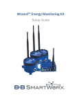
Wzzard™ Sensing Platform
Intelligent Edge Nodes
Operation Manual
International Headquarters
B&B Electronics Mfg. Co. Inc.
707 Dayton Road
Ottawa, IL 61350 USA
Phone (815) 433-5100 -- General Fax (815) 433-5105
Website: www.bb-elec.com
[email protected]
European Headquarters
B&B Electronics
Westlink Commercial Park
Oranmore, Co. Galway, Ireland
Phone +353 91-792444 -- Fax +353 91-792445
Website: www.bb-europe.com
[email protected]
Document: Wizard User Manual R0_5014m
2
CONTENTS
Warranty ........................................................................................................................................................................5
ABout the Wzzard Sensing Platform ..............................................................................................................................6
Wireless Connectivity Where You Need It .............................................................................................................6
Contents of Package ......................................................................................................................................................8
Hardware Installation ....................................................................................................................................................9
Connecting Your Sensor .............................................................................................................................................9
Connecting Your Sensor with Conduit models: Analog and Digital .......................................................................9
Connecting Your Sensor with M12 Models: Analog and Digital ..............................................................................13
Terminal Block Connections: Thermocouple ...........................................................................................................14
Powering Your Wzzard Edge Node ..........................................................................................................................15
Installing Batteries ...............................................................................................................................................15
LEDs .........................................................................................................................................................................15
Mount Your Wzzard Edge Node ..............................................................................................................................16
Connecting to Your Intelligent Edge Nodes via Bluetooth LE ......................................................................................17
Install the Wzzard App on Your Handheld Device ...................................................................................................17
CONFIGURING YOUR Wzzard Intelligent Edge Nodes .................................................................................................18
Radio ........................................................................................................................................................................18
Device Configuration ...............................................................................................................................................18
Geo Location ............................................................................................................................................................19
Analog Inputs ...........................................................................................................................................................19
Internal Temperature ..............................................................................................................................................20
Battery Voltage ........................................................................................................................................................20
Digital Inputs ............................................................................................................................................................21
Digital Outputs .........................................................................................................................................................22
Accelerometer .........................................................................................................................................................22
Configuration Button ...................................................................................................................................................24
3
Specifications, Intelligent Edge Nodes .........................................................................................................................25
Radio Specifications .....................................................................................................................................................27
Mechanical Drawing ....................................................................................................................................................29
Model Numbers ...........................................................................................................................................................30
Model Numbers for Wzzard Intelligent Edge Nodes with SmartMesh IP and Bluetooth LE ...............................30
Model Numbers for Wzzard Intelligent Edge Nodes with Bluetooth LE ..............................................................31
Model Numbers for Spectre Network Gateways .................................................................................................31
Declaration of Compliance ..........................................................................................................................................32
Declaration of Compliance CE .....................................................................................................................................33
B&B Electronics Technical Support ..............................................................................................................................34
4
WARRANTY
B&B Electronics warrants to the original end-user purchaser that this product, EXCLUSIVE OF SOFTWARE, shall be
free from defects in materials and workmanship under normal and proper use in accordance with B&B Electronics'
instructions and directions for a period of six (6) years after the original date of purchase. This warranty is subject
to the limitations set forth below.
At its option, B&B Electronics will repair or replace at no charge the product which proves to be defective within
such warranty period. This limited warranty shall not apply if the B&B Electronics product has been damaged by
unreasonable use, accident, negligence, service or modification by anyone other than an authorized B&B
Electronics Service Technician or by any other causes unrelated to defective materials or workmanship. Any
replaced or repaired products or parts carry a ninety (90) day warranty or the remainder of the initial warranty
period, whichever is longer.
To receive in-warranty service, the defective product must be received at B&B Electronics no later than the end of
the warranty period. The product must be accompanied by proof of purchase, satisfactory to B&B Electronics,
denoting product serial number and purchase date, a written description of the defect and a Return Merchandise
Authorization (RMA) number issued by B&B Electronics. No products will be accepted by B&B Electronics which do
not have an RMA number. For an RMA number, contact B&B Electronics at PHONE: (800) 624-1070 (in the U.S and
Canada) or (949) 465-3000 or FAX: (949) 465-3020. The end-user shall return the defective product to B&B
Electronics, freight, customs and handling charges prepaid. End-user agrees to accept all liability for loss of or
damages to the returned product during shipment. B&B Electronics shall repair or replace the returned product,
at its option, and return the repaired or new product to the end-user, freight prepaid, via method to be
determined by B&B Electronics. B&B Electronics shall not be liable for any costs of procurement of substitute
goods, loss of profits, or any incidental, consequential, and/or special damages of any kind resulting from a breach
of any applicable express or implied warranty, breach of any obligation arising from breach of warranty, or
otherwise with respect to the manufacture and sale of any B&B Electronics product, whether or not B&B
Electronics has been advised of the possibility of such loss or damage.
EXCEPT FOR THE EXPRESS WARRANTY SET FORTH ABOVE, B&B ELECTRONICS MAKES NO OTHER WARRANTIES,
WHETHER EXPRESS OR IMPLIED, WITH RESPECT TO THIS B&B ELECTRONICS PRODUCT, INCLUDING WITHOUT
LIMITATION ANY SOFTWARE ASSOCIATED OR INCLUDED. B&B ELECTRONICS SHALL DISREGARD AND NOT BE
BOUND BY ANY REPRESENTATIONS OR WARRANTIES MADE BY ANY OTHER PERSON, INCLUDING EMPLOYEES,
DISTRIBUTORS, RESELLERS OR DEALERS OF B&B ELECTRONICS, WHICH ARE
INCONSISTENT WITH THE WARRANTY SET FORTH ABOVE. ALL IMPLIED WARRANTIES INCLUDING THOSE OF
MERCHANTABILITY AND FITNESS FOR A PARTICULAR PURPOSE ARE HEREBY LIMITED TO THE DURATION OF THE
EXPRESS WARRANTY STATED ABOVE.
Every reasonable effort has been made to ensure that B&B Electronics product manuals and promotional materials
accurately describe B&B Electronics product specifications and capabilities at the time of publication. However,
because of ongoing improvements and updating of B&B Electronics products, B&B Electronics cannot guarantee
the accuracy of printed materials after the date of publication and disclaims liability for changes, errors or
omissions.
5
ABOUT THE WZZARD SENSING PLATFORM
WIRELESS CONNECTIVITY WHERE YOU NEED IT
The Wzzard™ intelligent wireless sensor platform makes it quick and easy to connect sensors and
communicate their data to your application, on your network or on the Internet, for visualization,
analytics or integration into business applications.
The Wzzard platform connects to a vast range of industry-standard sensors. It uses Intelligent Edge
Nodes and a wireless SmartMesh IP network to transmit sensor data to the Spectre Network Gateway.
The Spectre Network Gateway can connect to the Internet via wired connections or the cellular data
network.
Wzzard Intelligent Edge Nodes accommodate external sensors with a wide variety of sensor interface
options, including general purpose analog inputs, digital input/output and thermocouple. They can also
contain internal sensors like an accelerometer, depending upon the model number.
Secure, Reliable and Highly Scalable Wireless Networking
The Wzzard platform uses 802.15.4e wireless SmartMesh IP networking technology to deliver reliable,
resilient and scalable communication with advanced network management and comprehensive security
features. The platform uses full SmartMesh IP networking and time-synchronized channel hopping to
provide up to 99.999% connectivity, even in the most demanding RF environments.
The Wzzard wireless sensor platform enables rapid network deployment and expansion. New nodes
may be added at any time, and the SmartMesh network dynamically self-configures as new nodes are
added or removed. This process is a function of the mesh network itself, and does not need to be
controlled by the network gateway.
Easy Configuration and Installation
Configuration of the Wzzard sensor platform is easy via iOS or Android smart phones or tablets. Using
the Wzzard app, your handheld devices can configure the Wzzard Intelligent Edge Nodes over their
Bluetooth LE connections. The intelligent edge nodes can be configured with calibration and scaling
information, eng. units, friendly names, geolocation and other descriptive information. The MQTT-SN
protocol is used to transport sensor data to the network gateway. MQTT-SN is a highly efficient
publish/subscribe protocol optimized for sending sensor data over wireless networks.
The platform simplifies physical installation as well. The Wzzard Intelligent Edge Nodes can be attached
to any surface using screws or their embedded magnetic bases. The IP67-rated, fiber reinforced
polyester PBT housing and the ability to connect to external sensors via conduit fitting cable gland or
M12 connector make the units deployable in virtually any industrial or commercial environment.
Intelligence at the Network Edge
The Wzzard wireless platform places intelligence at the network edge. The Wzzard Intelligent Edge
Nodes can be configured to communicate data only when specified threshold or alert levels are
exceeded. When reporting, they can associate useful information like geo-location, device name and
uptime. This eliminates unnecessary network traffic, eases the processing burden on upstream
resources, and cuts the cost of cellular data plans when the Gateway is using the cellular data network.
6
Thanks to low-power wireless technology and programmable time synchronization, the Intelligent Edge
Nodes can operate for up to five years on just two AA lithium batteries.
The Spectre Network Gateway
The Spectre Network Gateway connects to the SmartMesh IP wireless mesh network and the Wzzard
Intelligent End nodes through an integrated 802.15.4e radio. The Spectre Network Gateway receives the
incoming data stream from edge nodes in MQTT-SN format and converts the information into MQTT
protocol for transport to an MQTT broker on your network or on the Internet.
Uniquely designed with open source LINUX architecture, the Spectre Network Gateway is customizable
through installation of software plug-in modules. Users can create their own plug-in modules with
common LINUX commands and scripts, or add them from B&B’s existing library. Plug-in modules are
available for establishing communications with the MQTT broker within a number of IoT application
platform providers, including Axeda, Xivley, ILS and SeeControl.
The Spectre Network Gateway is built for plug-and-play simplicity with extensive remote management,
deployment and customization options. It connects Ethernet equipment and other devices to the
Internet or intranet via either cellular 3G or 10/100 wired Ethernet. The standard configuration includes
a 10/100 Ethernet port, USB host port, binary input/output (I/O) port and an 802.15.4e radio. It also has
an auxiliary port that can be configured for other purposes, like Ethernet or RS-232/485/422.
Secure Connections
To ensure secure communications the Spectre Network Gateway supports the creation of VPN tunnels
using IPsec, OpenVPN and L2TP. The web interface provides detailed statistics about gateway activities,
signal strength, etc. The gateway supports DHCP, NAT, NAT-T, DynDNS, NTP, VRRP, control by SMS, and
many other routing functions. The Spectre Network Gateway also provides diagnostic functions which
include automatically monitoring the PPP connection, automatic restart in case of connection losses,
and a hardware watchdog that monitors the Spectre Network Gateway status.
7
CONTENTS OF PACKAGE
The package includes:
• Wzzard Intelligent Edge Node
• Sensor wire harness cable - conduit connection models only
• 2 3.6V AA Thionyl Chloride Lithium Batteries
• External Antenna (some models)
• Quick Start Guide
8
HARDWARE INSTALLATION
CONNECTING YOUR SENSOR
CONNECTING YOUR SENSOR WITH CONDUIT MODELS: ANALOG AND DIGITAL
Thread the wire harness through the conduit.
Plug the included wire harness into the receptacle on the circuit board inside the node.
Connect your sensor to the wires running from the node’s conduit. Consult the charts below for wire
colors and connections.
9
WIRING FOR WZZARD
1
Brown
WSD2CTJ
3.3V
WSD1CTJ
3.3V
WSD2CTK 3.3V
WSD1CTK 3.3V
WSD2XV0 3.3V
WSD1XV0 3.3V
WSD2CA2 3.3V
WSD1CA2 3.3V
WSD2CD2 3.3V
WSD1CD2 3.3V
WSD2CA3 3.3V
WSD1CA3 3.3V
WSB1CTJ
3.3V
WSB1CTK 3.3V
WSB1CA2 3.3V
INTELLIGENT EDGE NODES WITH SMARTMESH IP – CONDUIT MODELS
2
3
4
5
6
7
8
Red
Pink
Yellow
Green
Blue
White
Gray
DO
GND
GND
DO
GND
GND
DO
GND
GND
DO
GND
GND
GND
GND
AIN1
GND
AIN2
GND
DO
3.3REF
GND
AIN1
GND
AIN2
GND
DO
3.3REF
GND
DIN1
DIN2
DO1
DO2
GND
GND
GND
DIN1
DIN2
DO1
DO2
GND
GND
GND
AIN1
GND
AIN2
GND
AIN3
GND
GND
AIN1
GND
AIN2
GND
AIN3
GND
GND
DO
GND
GND
DO
GND
GND
AIN1
GND
AIN2
GND
DO
3.3REF
GND
WSB1CD2 3.3V
DIN1
3.3V = 3.3V power input
3.3REF= 3.3V output reference
AIN1= Analog Input #1
AIN2= Analog Input #2
AIN3= Analog Input #3
DO = Digital Output
DIN1= Digital Input #1
DIN2= Digital Input #2
D01= Digital Output #1
D02= Digital Output #2
GND= Ground Input
DIN2
DO1
DO2
10
GND
GND
GND
WIRING FOR WZZARD INTELLIGENT EDGE
1
2
3
White
Brown
Green
WSD2MA2 3.3V
AIN1
GND
WSD1MA2 3.3V
AIN1
GND
WSD2MD2 3.3V
DIN1
DIN2
WSD1MD2 3.3V
DIN1
DIN2
WSD2MA3 3.3V
AIN1
GND
WSD1MA3 3.3V
AIN1
GND
WSB1MA2 3.3V
AIN1
GND
WSB1MD2 3.3V
DIN1
DIN2
3.3V = 3.3V power input
3.3REF= 3.3V output reference
AIN1= Analog Input #1
AIN2= Analog Input #2
AIN3= Analog Input #3
DO = Digital Output
DIN1= Digital Input #1
DIN2= Digital Input #2
D01= Digital Output #1
D02= Digital Output #2
GND= Ground Input
NODES WITH SMARTMESH IP – M12 MODELS
4
5
6
7
8
Yellow
Gray
Pink
Blue
Red
AIN2
GND
DO
3.3REF
GND
AIN2
GND
DO
3.3REF
GND
DO1
DO2
GND
GND
GND
DO1
DO2
GND
GND
GND
AIN2
GND
AIN3
GND
GND
AIN2
GND
AIN3
GND
GND
AIN2
GND
DO
3.3REF
GND
DO1
DO2
GND
GND
GND
11
WIRE COLORS FOR WZZARD INTELLIGENT EDGE NODES WITH BLUETOOTH LE (4.0)
1
Brown
2
Red
3
Pink
4
Yellow
WSB 1MTJ
WSB 1CTJ
WSB 1MTK
WSB 1CTK
WSB 1MA2
WSB 1CA2
WSB 1MD2
WSB 1CD2
3.3V = 3.3V power input
3.3REF= 3.3V output reference
AIN1= Analog Input #1
AIN2= Analog Input #2
AIN3= Analog Input #3
DO = Digital Output
DIN1= Digital Input #1
DIN2= Digital Input #2
D01= Digital Output #1
D02= Digital Output #2
GND= Ground Input
12
5
Green
6
Blue
7
White
9
Gray
CONNECTING YOUR SENSOR WITH M12 MODELS: ANALOG AND DIGITAL
While installing your batteries, confirm that the wire harness from the M12 port is connected to the circuit board
inside in Wzzard Edge Node.
Wire your M12 cable according to the charts below.
Wzzard M12 Pinout
13
TERMINAL BLOCK CONNECTIONS: THERMOCOUPLE
Remove the (4) screws that hold the top of the Wzzard node in place. Thread the thermocouple wires through the
conduit and attach them to the terminal block.
1 = Thermocouple input #1 positive (+)
2 = Thermocouple input #1 negative (-)
3 = Thermocouple input #2 negative (-)
4 = Thermocouple input #2 positive (+)
Close the Wzzard node and replace the (4) screws.
14
POWERING YOUR WZZARD EDGE NODE
INSTALLING BATTERIES
Remove the (4) black screws that hold the top of the node in place.
Install (2) 3.6 V AA Thionyl Chloride lithium batteries.
As with all batteries, these are a fire, explosion, and severe burn hazard. Do not burn or expose them to high
temperatures. Do not recharge, crush, disassemble, or expose the contents to water. Properly dispose of used
batteries according to local regulations by taking it to a hazardous waste collection site, an e-waste disposal center,
or other facility qualified to accept lithium batteries.
LEDS
After you have installed the batteries the LED will begin to blink. This indicates that the Node is
attempting to establish a network connection. The LED will cease blinking when a connection is made.
Status LED
Data
Solid On
Module startup initialization, approx. 10 sec.
Slow Blink
Attempting to establish connection with
SmartMesh IP network – 1 sec on/1 sec off
Fast Blink
Firmware Update in progress – 10 blinks per sec
OFF
Unit is connected to wireless network
15
MOUNT YOUR WZZARD EDGE NODE
Wzzard nodes may be mounted either with screws or with their internal magnets.
Flange Mounting
Magnetic Mounting
Wzzard nodes may be mounted via their
mounting ears. (M5, #10)
Wzzard nodes contain a powerful, internal
mounting magnet. (Pull force 4.7 lbs, 2.13 kg)
The magnet is in the base of the Wzzard node.
16
CONNECTING TO YOUR INTELLIGENT EDGE NODES VIA BLUETOOTH LE
INSTALL THE WZZARD APP ON YOUR HANDHELD DEVICE
You may Install the Wzzard app on your Android or IOS handheld device. Your handheld device must be
compatible with Bluetooth LE 4.0.
The Android APP version is available on Playstore
The IoS APP version is here on Apple App Store (iTunes)
The APP can also be downloaded from http://www.bb-smartsensing.com/xxxxxxxx
1. Open the Wzzard App
2. Press the “Configuration’ button on the device for at least 1 second to wake up Bluetooth radio (the
LED will come on to signify this)
3. Press the device you would like to view. (This screen lets the user view Bluetooth advertisements
from the Nodes.)
4. Press the Configure Device button.
5. Pair with the device. Defaults are admin/admin.
6. Press the “Radio Setup’ button to set the Network ID and Network Join Key. (These must be the same
values that you enter in the corresponding network gateway.)
Press the ‘Save’ button to save the new settings.
7. Refer to the Wzzard Platform App User manual for further node programming instructions.
Documents can be found at http://www.bb-smartsensing.com
17
CONFIGURING YOUR WZZARD INTELLIGENT EDGE NODES
RADIO
Configuration
Screen
Radio
Parameter
Parameter
Range
Default
Value
Description
Network ID
1-65534
1981
Join Duty
Cycle
0.2-99.8
25%
Network Join
Key
32 hexadecimal
characters
On/Off
Wzzard
Smartworx
Unique identifier for the sensor network.
This ID must match the gateway.
The percent of time that the node will
be awake. A higher value allows the
node to connect to the gateway faster
but uses more battery current.
128-bit encryption key for the network
10-86400
seconds
16
characters
16
characters
10
Enables sensor broadcast messages over
the Bluetooth LE interface while the
node is asleep.
Interval between broadcast messages.
admin
Login name for configuring the node
admin
Password for configuring the node
Advertise
During Sleep
Advertise
Rate
Username
Password
Enabled
DEVICE CONFIGURATION
Configuration
Screen
Device
Configuration
Parameter
Parameter
Range
Description
0-40
characters
0, 10-86400
seconds
Exceptionbased
Measurement
Interval
Publish
Interval
10 seconds
to 23:59:59
hours
Default
Value
Description
User-defined text field
0
Determines how frequently the node will
wake up to check for an exception
60
Determines the interval between publishes
to the broker.
18
GEO LOCATION
Configuration
Screen
Geo Location
Parameter
Parameter
Range
Default
Value
Description
Latitude
-90 to 90
degrees
-180 to 180
degrees
-999999.9
to 999999.9
32
characters
0.0
Geographical location of the sensor
0.0
Geographical location of the sensor
0.0
Elevation of the sensor
geoloc
User defined text field to describe the
sensor
Parameter
Parameter
Range
Default
Value
Description
Sensor Enable
On/Off
On
Analog Input
Type
0-20mA, 420mA, 0-5V,
1-5V
32
characters
8 characters
0-5V
Enables publishing of the sensor data to
the broker
The type of sensor connected to the input
ain1
User-defined text field to describe the
sensor
Engineering unit of measure
-999999.9
to 999999.9
-999999.9
to 999999.9
On/Off
5.0
The value that is reported when the input
is at the maximum value
The value that is reported when the input
is at the minimum value
Enables publishing of the sensor data to
the broker when an alert level is reached
The node will initially send an update to
the broker when the input exceeds this
value. The node will subsequently send 5
more updates at 1 minute intervals to the
broker.
The node will initially send an update to
the broker when the input exceeds this
value. The node will subsequently send 5
more updates at 1 minute intervals to the
broker.
Longitude
Elevation
Sensor Label
ANALOG INPUTS
Configuration
Screen
Analog Inputs
Sensor Label
Measurement
Unit
Sensor Span
Point
Sensor Zero
Point
Enable
Exception
Alert High
Alert Low
0.0
On
-999999.9
to 999999.9
-999999.9
to 999999.9
19
BLE
On/Off
Advertisement
Enable
On
When enabled, the node will broadcast the
sensor value over the Bluetooth interface.
INTERNAL TEMPERATURE
Configuration
Screen
Internal
Temperature
Parameter
Parameter
Range
Default
Value
Description
Sensor Enable
On/Off
On
Sensor Label
32
characters
Cel/[degF]
temp1
Enables publishing of the sensor data to
the broker
User-defined text field to describe the
sensor
Engineering unit of measure
On/Off
On
Measurement
Unit
Enable
Exception
Alert High
Alert Low
C
-999999.9
to 999999.9
-999999.9
to 999999.9
BLE
On/Off
Advertisement
Enable
On
Enables publishing of the sensor data to
the broker when an alert level is reached
The node will initially send an update to
the broker when the input exceeds this
value. The node will subsequently send 5
more updates at 1 minute intervals to the
broker.
The node will initially send an update to
the broker when the input exceeds this
value. The node will subsequently send 5
more updates at 1 minute intervals to the
broker.
When enabled, the node will broadcast the
sensor value over the Bluetooth interface.
BATTERY VOLTAGE
Configuration
Screen
Battery
Voltage
Parameter
Parameter
Range
Default
Value
Description
Sensor Enable
On/Off
On
Sensor Label
32
characters
Volts
vbatt
Enables publishing of the sensor data to
the broker
User-defined text field to describe the
sensor
Engineering unit of measure
Measurement
Unit
V
20
Enable
Exception
Alert High
On/Off
Alert Low
-999999.9
to 999999.9
On
-999999.9
to 999999.9
BLE
On/Off
Advertisement
Enable
On
Enables publishing of the sensor data to
the broker when an alert level is reached
The node will initially send an update to
the broker when the input exceeds this
value. The node will subsequently send 5
more updates at 1 minute intervals to the
broker.
The node will initially send an update to
the broker when the input exceeds this
value. The node will subsequently send 5
more updates at 1 minute intervals to the
broker.
When enabled, the node will broadcast the
sensor value over the Bluetooth interface.
DIGITAL INPUTS
Configuration
Screen
Digital Inputs
Parameter
Parameter
Range
Default
Value
Description
Sensor Enable
On/Off
On
Sensor Label
32
characters
8 characters
din1
Enables publishing of the sensor data to
the broker
User-defined text field to describe the
sensor
Engineering unit of measure
Boolean,
Count, Rate
Boolean The type of sensor connected to the input either a boolean input, a counter/totalizer,
or a rate meter.
On
Enables publishing of the sensor data to
the broker when an alert level is reached
The node will initially send an update to
the broker when the input exceeds this
value. The node will subsequently send 5
more updates at 1 minute intervals to the
broker.
The node will initially send an update to
the broker when the input exceeds this
value. The node will subsequently send 5
more updates at 1 minute intervals to the
broker.
Off
Changes the input from an active high
input to an active low input.
On
When enabled, the node will broadcast the
sensor value over the Bluetooth interface.
Measurement
Unit
Digital Input
Type
Enable
Exception
Alert High
On/Off
Alert Low
-999999.9
to 999999.9
Invert Input
On/Off
-999999.9
to 999999.9
BLE
On/Off
Advertisement
21
Enable
True Message
8 characters
False Message
8 characters
Minimum On
Time
seconds
Period
Multiplier
seconds
-999999.9
to 999999.9
1
1
Parameter
Parameter
Range
Default
Value
Description
Sensor Enable
On/Off
On
Sensor Label
32
characters
On/Off
On/Off
do1
Enables publishing of the sensor data to
the broker
User-defined text field to describe the
sensor
Inverts the level of the output.
When enabled, the node will broadcast the
sensor value over the Bluetooth interface.
Message that is displayed when the
boolean input is true.
Message that is displayed when the
boolean input is false.
The minimum amount of time that the
input signal must be low or high before it is
registered as a valid pulse.
Update frequency for the rate meter.
The scale factor for the counter and rate
meter.
DIGITAL OUTPUTS
Configuration
Screen
Digital
Outputs
Invert Output
BLE
Advertisement
Enable
Off
On
ACCELEROMETER
Configuration
Screen
Accelerometer
Parameter
Parameter
Range
Default
Value
Description
Sensor Enable
On/Off
On
Sensor Label
32
characters
8
characters
On/Off
accel1
Enables publishing of the sensor data to
the broker
User-defined text field to describe the
sensor
Engineering unit of measure
2G, 4G, 8G
4G
Measurement
Unit
BLE
Advertisemen
t Enable
Acceleromete
G
On
22
When enabled, the node will broadcast
the sensor value over the Bluetooth
interface.
Measurement range of the
r Granularity
Acceleromete
r Interval
12.5, 25,
50, 100,
200, 400Hz
100Hz
23
accelerometer. A lower value will increase
the sensitivity of the accelerometer.
Frequency Response of the
accelerometer. A higher value will allow
the accelerometer to capture faster
events.
CONFIGURATION BUTTON
When you press and hold the “Configuration” button on the Node for more than 5 seconds it will:
-
LED will flash quickly a couple times
Restore the BLE login and password/encryption key/encryption enable.
Restart the device.
This action will not reset the device back to factory settings.
When you press and hold the “Configuration” button on the node for at least 1 second but less than 5
seconds it will:
-
LED will turn on (hold button until LED is seen)
will Wake-up the device and turn on the BLE radio
This will enable the Wzzard APP to communicate to the node
24
SPECIFICATIONS, INTELLIGENT EDGE NODES
Power Supply
Sources
External Input
Voltage
Connectors
2 Lithium Primary Cells in parallel. Optional External Supply
3.3 VDC +/- 5%
M12
1/2” Conduit, sensor interface cable included; 8 wire, 26 gage, 6 ft.
Battery Life
Multiple years based on 1 min sensor sampling and reporting
Environmental -- Intended for indoor and outdoor use.
Operating
-40 to 80 ºC
Temperature
Storage Temperature -40 to 85ºC
Operating Humidity
0 to 95% non-condensing
LED indicators
One Green LED
Data
Color = Green
Blink = Attempting to establish network connection
Off = Device connected to network
Enclosure Rating
Rating
IP66-rated, fiber reinforced polyester PBT
Mounting
Mountable by use of magnets or mounting ears
Certifications
FCC
FCC Part 15 Class A
FCC - Part 15.247; Industry Canada - RSS210; CSA – Class 1, Div 2 Groups A,
B, C, D (ANSI/UL equivalent)
CE
EN55022
CISPR (EN55022) Class A
EN61000-6-1
Generic Standards for Residential, Commercial, & Light Industrial
EN61000-6-2
Radiated immunity 10 V/m, 80-2700 MHz (EN61000-6-2) or Equivalent
EN61000-4-2
(ESD) +/- 15kV contact, +/- 4kV air
EN61000-4-3
(RFI)
EN61000-4-4
EFT
EN61000-4-5
Surge
EN61000-4-6
CI
EN61000-4-6
Power Frequency Magnetic
EN61000-4-11
Voltage Dips & Interruptions
EN60255-21-1
Vibration
EN60255-21-2
Shock
IEC
Shock and
IEC 60068-2-27:2008 shock, 50g, 11ms half sine wave, 18 shocks
Vibration
IEC 60068-2-6:2007 vibration, 2g, 10-500 Hz,1.5mm displacement
Radiated immunity
10 V/m, 80-2700 MHz (EN61000-6-2) or Equivalent
FCC
FCC Part 15 Class A
FCC - Part 15.247
25
Industry Canada - RSS210
CSA – Class 1, Div 2 Groups A, B, C, D (ANSI/UL equivalent
Regulatory Approvals
ROHS and WEEE Compliant
Digital Inputs
Voltage range
0 – 48 VDC
VIL
0.97V Maximum
VIH
1.8V Minimum
Pull up current
32uA
Type
Sourcing (PNP)/Sinking (NPN) Software selectable input
Isolation
None
Rate/Frequency Inputs
Frequency
Does a 1 second measurement at each measurement/publish interval
Can handle frequencies between 1 Hz - 1000 Hz
Uses the falling edge or rising edge based on the Invert Enabled setting
Counter Input
Channels
Actively counts either the falling edge (Invert enabled) or rising edge (Invert
disabled)
Can use a multiplier to convert to a unit type or count
2 selectable/shared with Digital inputs
Rolls over at 999999.9
Analog Inputs
Input ranges
0-5 VDC, 0–20 mA
Accuracy @ 25ºC
Voltage: 0.10% full scale reading, 0.20% max.
Current: 0.11% full scale reading, 0.24% max.
Resolution
12 bit
Input load
100 Mega ohm (0-5VDC), 250ohm (0-20ma)
resistance
Thermocouple Input
Types Supported
J and K
Ranges Supported
Type J -210 to +1,200 °C
Type K -270 to +1,372 °C
Resolution
0.25°C
Accuracy
Typical +/-2°C
+/- 6°C over the temperature range of -40 to 80°C
Digital Outputs
Voltage range 0-30 VDC
Output Type Open Drain
Output Current Not to be less than 100ma
Protection Current Limit Protection
Isolation None
26
RADIO SPECIFICATIONS
SmartMesh IP 802.15.4e RADIO SPECIFICATIONS
Parameter
Conditions
Min
Frequency Band
Typ
2,400
Max Units
2,4835 GHz
Number of
Channels
15
Channel
Separation
5
MHz
2405 + 5*(k-11)
MHz
250
kbps
100
m
300
m
1200
m
Channel Clear
Frequency
Modulation
IEEE 802.15.4 Direct Sequence
Spread Spectrum (DSSS)
Raw Data Rate
Range
25 °C, 50% RH, +2dBi OmniDirectional Antenna, Antenna 2 m
above
Indoorground
Outdoor
Free Space
m
Receiver
Sensitivity
Packet Data Error Rate (PER) = 1%
-93
dBm
Receiver
Sensitivity
PER = 50%
-95
dBm
Output Power
Delivered to a 50 Ω load
High Calibration
Setting
8
dBm
Low Calibration
Setting
0
dBm
27
BLUETOOTH LE RADIO SPECIFICATIONS
No Characteristics
1
. Operation Frequency
Range
Conditions
2 Channel Spacing
3 Output Power
4 Sensitivity, High Gain
Mode
Min
2402
Typ
Max
2480
Units
MHz
2
MHz
4
dBm
-24
dBm
Maximum setting, measured
at single ended 50ohm.
Minimum setting, measured
at single ended 50ohm.
High Gain Mode
-93.0
-70
dBm
Standard Mode
-92.5
-70
dBm
THIONYL CHLORIDE LITHIUM BATTERIES (2 SUPPLIED WITH PRODUCT)
Characteristics
Conditions
Temperature Range
-40 to 85°C
Nominal Capacity
2.4 Ah
Nominal Voltage
3.6 V
Diameter
14.5 mm
Height
50.5 mm
*Potential hazard: Do not recharge, crush, disassemble or heat above 212°F (100°C)
28
MECHANICAL DRAWING
Figure 1: Mechanical drawing
29
MODEL NUMBERS
MODEL NUMBERS FOR WZZARD INTELLIGENT EDGE NODES WITH SMARTMESH IP AND
BLUETOOTH LE
Wzzard Intelligent Edge Nodes with SmartMesh IP and Bluetooth LE
Model Number
Thermocouple
WSD1CTK
Wireless Mesh 802.15.4e; 2 Thermocouple J-type inputs, 1 Digital Output; External Antenna,
Conduit Connector
Wireless Mesh 802.15.4e; 2 Thermocouple J-type inputs, 1 Digital Output; Internal Antenna,
Conduit Connector
Wireless Mesh 802.15.4e; 2 Thermocouple K-type inputs, 1 Digital Output; External Antenna,
Conduit Connector
Wireless Mesh 802.15.4e; 2 Thermocouple K-type inputs, 1 Digital Output; Internal Antenna,
Conduit Connector
Model Number
Accelerometer and Temperature Sensor
WSD2XV0
WSD1XV0
Wireless Mesh 802.15.4e Integrated Motion Sensor/Accelerometer; External Antenna
WSD2CTJ
WSD1CTJ
WSD2CTK
Wireless Mesh 802.15.4e Integrated Motion Sensor/Accelerometer; Internal Antenna
Model Number
Analog Inputs
WSD2MA2
Wireless Mesh 802.15.4e; 2-Analog Inputs, 1 Digital Output; External Antenna, M12
Connector
WSD1MA2
Wireless Mesh 802.15.4e; 2-Analog Inputs, 1 Digital Output; Internal Antenna, M12 Connector
Wireless Mesh 802.15.4e; 2-Analog Inputs, 1 Digital Output; External Antenna, Conduit
Connector
Wireless Mesh 802.15.4e; 2-Analog Inputs, 1 Digital Output; Internal Antenna, Conduit
Connector
WSD2CA2
WSD1CA2
WSD2MA3
WSD1MA3
WSD2CA3
WSD1CA3
Model Number
Wireless Mesh 802.15.4e; 3-Analog Inputs; External Antenna, M12 Connector
Wireless Mesh 802.15.4e; 3-Analog Inputs; Internal Antenna, M12 Connector
Wireless Mesh 802.15.4e; 3-Analog Inputs; External Antenna, Conduit Connector
Wireless Mesh 802.15.4e; 3-Analog Inputs; Internal Antenna, Conduit Connector
Digital Inputs
WSD2CD2
Wireless Mesh 802.15.4e; 2 Digital Inputs, 2 Digital Outputs; External Antenna, M12
Connector
Wireless Mesh 802.15.4e; 2 Digital Inputs, 2 Digital Outputs; Internal Antenna, M12
Connector
Wireless Mesh 802.15.4e; 2 Digital Inputs, 2 Digital Outputs; External Antenna, Conduit
Connector
WSD1CD2
Wireless Mesh 802.15.4e; 3-Analog Inputs; Internal Antenna, Conduit Connector
WSD2MD2
WSD1MD2
30
MODEL NUMBERS FOR WZZARD INTELLIGENT EDGE NODES WITH BLUETOOTH LE
Wzzard Intelligent Edge Nodes with Bluetooth LE
Model Number
WSB1CTJ
WSB1CTK
Model Number
WSB1MA2
WSB1CA2
Model Number
WSB1MD2
WSB1CD2
Temperature
Bluetooth; 2 Thermocouple J-type inputs, 1 Digital Output, Conduit
Connector
Bluetooth; 2 Thermocouple K-type inputs, 1 Digital Output, Conduit
Connector
Analog
Bluetooth; 2 Analog Inputs, 1 Digital Output, M12 Connector
Bluetooth; 2 Analog Inputs, 1 Digital Output, Conduit Connector
Digital
Bluetooth; 2 Digital Inputs, 2 Digital Outputs; M12 Connector
Bluetooth; 2 Digital Inputs, 2 Digital Outputs; Conduit Connector
MODEL NUMBERS FOR SPECTRE NETWORK GATEWAYS
Spectre Network Gateway Models
ERT351
RT3G-350
RT3G-351
RT3G-352
RT3G-354
Ethernet Network Gateway with 2 Ethernet ports, wireless mesh 802.15.4e
Cellular/Ethernet Network Gateway with 1 Ethernet port, wireless mesh
802.15.4e
Cellular/Ethernet Network Gateway with 2 Ethernet ports, wireless mesh
802.15.4e
Cellular/Ethernet Network Gateway with 1 Ethernet port, 1 RS-232 port,
wireless mesh 802.15.4e
Cellular/Ethernet Network Gateway with 1 Ethernet port, 1 RS-485 port,
wireless mesh 802.15.4e
31
DECLARATION OF COMPLIANCE
32
DECLARATION OF COMPLIANCE CE
33
B&B ELECTRONICS TECHNICAL SUPPORT
Phone:
Fax:
Email:
Web:
1-800-346-3119
(Monday - Friday, 7 a.m. to 7 p.m. CST)
815-433-5109E-Mail:
[email protected]
www-bb-elec.com
34