1
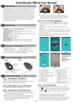
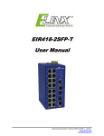
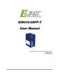
Wzzard™ Energy Monitoring Kit Setup Guide International Headquarters B+B SmartWorx. 707 Dayton Road Ottawa, IL 61350 USA Phone (815) 433-5100 -- General Fax (815) 433-5105 Website: www.bb-smartworx.com [email protected] European Headquarters B+B SmartWorx Westlink Commercial Park Oranmore, Co. Galway, Ireland Phone +353 91-792444 -- Fax +353 91-792445 Document: 710-10441-00_WSKIT3BE-NRG _R1_ SetupGuide_4615 2 ENERY MONITORING KIT The Wzzard™ Energy Monitoring Application makes it simple to see the real time and historical electrical consumption of any individual machine or panel. Data can be exported for further analysis. Email or text message alerts can be sent when user-configured high or low limits are exceeded in critical applications. Installation costs are kept low using the Wzzard wireless sensing platform. The platform creates a self-forming, self-healing wireless mesh network that eliminates the need for wires and requires no special skills to install. Each Wzzard sensor node is powered by long life batteries. Install the monitoring software on your Windows PC. You can monitor the energy dashboard on that machine, or configure it to serve web pages that you can monitor from any web browser on your network. The contents of the kit include: Qty 3 WSD2MA3 3 Analog in units with M12 connector and external antenna Qty 6 JC10F50-V 50A clamp on current sensor Qty 2 JC24S250-V 250A clamp on current sensor Qty 3 520-10256-00 M12 Cables Qty 1 ERT-351 Ethernet Gateway with Dust Manager board Qty 1 750-21265-00 USB flash drive (2GB) with B-Scada dashboard and User Manual SMARTMESH IP SET UP GUIDELINES While a Wzzard network is self-forming, self-managing and self-optimizing, there are a few simple, but critical, pieces that you must include at the planning stage before deploying a Wzzard network The key to planning a quality Wzzard network is to provide the Wzzard Network Gateway with the building blocks it needs to build a robust network. For maximum reliability, each Wzzard node should have more than one path back to the gateway. Each Wzzard node is also a repeater node so arrange your network so every node has more 3 than one neighbor. Placing Nodes within range of only one other device along a maximally spaced string will result in a fragile network that is prone to Node resets and data loss. The first hop Nodes are the devices that will be placed within range of the Network Gateway Node, and within range of each other. As you add nodes to your network, you should ensure that you have multiple nodes in range of the gateway. Device placement can change the effective range by orders of magnitude. At one end of the spectrum, devices placed on elevated poles or towers with clear line of sight to other Nodes in the network may have a range of 1000m or more. At the other end, devices placed on the ground or next to large metal objects may have an effective range of 10m or less. The most accurate way to estimate range is to evaluate range in a real environment using the same placement methods that will be used in the final installation. That being said, it is convenient to use as a starting point. To begin with, we recommend that customers plan on their devices working at a spacing of 50m for Nodes with internal antennas or 100m for Nodes with external antenna for a typical indoor application. In a typical outdoor installation these numbers can be doubled to 100m for internal antennas and 200m for external antennas. Analysis of the first of several 'typical' deployments can guide the typical range number up or down. Here are some best practices for deploying Edge Nodes: It is better to place a device at its final location and then have it join the network than to form your network ahead of time and subsequently scatter Nodes around the site Guarantee that the device hardware is working before it is installed. This can be done by pushing the configuration button and checking the status LED. A single blink will occur if the Node is active Install the Gateway first and then devices at the 1st hop and so on. If you have pre-planned for each Node to have multiple neighbors, it is not necessary to wait for a Node to join before proceeding to the installation of the next Node. It is more important to verify that each device is on, and then to verify that all devices have joined at the Gateway by checking the status LED. The status LED will stop blinking when the Node has successfully joined the network. It is better not to install devices very close to ground. It is preferable to install them at least 1m above ground. It is better to place devices away from any flat metal objects. (At least 12cm away if possible) To join the network, the Node must be configured with the correct Network ID and Join Key that bind the device to the network. These parameters are persistent and should be set up once prior to installation. Refer to quick start guide for programming information. A Node’s Network ID must match the Network ID of the Gateway of the intended network. If multiple networks are operating on the site, additional care should be taken to ensure that the Nodes’ Network IDs are set correctly. Similarly, if a Node moves from one location to another in the deployment space, it may leave its current Network ID and may not be able to rejoin. Nodes use a Join Key to encrypt the initial join request when joining a network. If the Join Key used by the Node does not match the Node's Join Key configured on the Gateway, the Gateway will not be able to decrypt the join message and will not allow the Node to join the network. For ease of use, we recommend using a single, deployment-specific Join Key shared by all Nodes but unique to the customer. This will prevent malicious devices from joining the network. This means that a Node need only be configured with the secure common Join Key to join the network. 4 SPECTRE GATEWAY SETUP 1. 2. 3. 4. 5. 6. Attach the antenna to the AUX port. Attach the Ethernet cable to the ETH port on the gateway and the other end to your PC You will use an Ethernet connection to configure the gateway and to communicate with it. Attach Power Apply +10 to +30 V DC. The gateway has built-in protection against reverse polarity. Configure the gateway The default gateway IP address is: 192.168.1.1 Default Username = root Default Password = root Important! Please change your password. To do this select Change Password item under Administration section of the main menu. Connect to the web client Select the User Modules item under the Customization section of the main menu to view and configure the IoT Gateway user module. Note: If you are having trouble connecting to the gateway, be sure that the PC is setup to use DHCP or has a static 192.168.1.x IP address. 7. This web page shows the user modules that have been loaded into the gateway and the version number of each module. Click on the IoT Gateway User Module to bring up the configuration screen. 5 8. The IoT Gateway Settings screen contains sections for configuring the sensor network, the internal MQTT broker, and the MQTT Bridge to an external cloud partner. At a minimum, enable the MQTT Broker Enable and click on the Save button to store the settings in the gateway. DOWNLOAD B+B SMARTWORX WZZARD SENSOR BLE APP Wzzard nodes are configured using Bluetooth from a supported Android device. The application can be found on the Google Play Store with the name “B+B SmartWorx Wzzard Sensor”. Your Android device must support Bluetooth low energy or “Bluetooth LE”. 1. 2. Go to the Google Play Store and search for “B+B SmartWorx Wzzard Sensor”. Install the app POWER UP WZZARD EDGE NODE 1. 2. 3. 4. 5. Remove the (4) black screws that hold the top of the node in place Install your batteries Use (2) 3.6V 2400 mAH Lithium Thionyl Chloride AA batteries. Install the battery clip Replace the cover and tighten the (4) screws. Screws must be tightened to 5 in-lb torque in order to maintain IP66 rating. (This can be accomplished via hand tightening.) Check LED 6 After you have installed the batteries the LED will begin to blink. This indicates that the Node is attempting to establish a network connection. The LED will cease blinking when a connection is made. Status LED Data 6. Solid On Slow Blink (1 per sec) Fast Blink (10 per sec) OFF Module startup initialization, approx. 10 sec. Attempting to establish connection with SmartMesh IP network Firmware Update in progress Unit is connected to wireless network Attach the External Antenna Note: The best way to remove the clip is to insert a small flathead screwdriver between the batteries and the clip, parallel to the batteries, and give the screwdriver a gentle twist. This will remove the clip without damage. 7 SETTING UP WZZARD EDGE NODES 1. 2. 3. Run the Wzzard Sensor app on your Android device Press the Configuration Button on the node. Within 3 minutes of pressing the button, select the Node you desire to configure. The advertise screen appears. The data comes from BLE advertisements, provided that advertisements are enabled. The advertisement data will not update when you are paired with the unit. 4. 5. Press the “Configure Device” button on the App. This will pop up a window that allows you to pair with the device and enter configuration parameters. Login to the node: The default username and password are: Username = “admin” Password = “admin” Note: When you enter the login information the Wzzard Intelligent Edge Node will pair with your handheld device. A popup screen will appear during the pairing process. 8 When the pairing process is complete you will be taken to a menu screen that allows you to begin configuring your Wzzard Intelligent Edge Node. There are four main areas: Radio Setup Configure Network Bluetooth LE Settings Sensor Setup Configure internal and external sensors Device Info Wzzard Intelligent Edge Node information Firmware Update Update the firmware over the air using Bluetooth. 6. 7. 8. Click the Sensor Setup button Set the Publish interval for the Wzzard node. The default is 1 minute. Shorter intervals will reduce battery life. Set the Sensor Span Point and Sensor Zero Point for each sensor. This range should match the sensor range stated in the table below. Sensor JC10F50-V JC24S250-V Span Point 50 250 Zero Point 0 0 9 ATTACHING THE SENSORS ON THE INTELLIGENT EDGE NODES 1. Wire Your Sensors You can connect up to 3 sensors to a Wzzard node. Sensor Sensor 1 Sensor 2 Sensor 3 Wzzard Industrial Node with M12 cable -- wire color Sensor(+) to M12 cable BROWN Sensor (-) to M12 cable GREEN Sensor(+) to M12 cable YELLOW Sensor (-) to M12 cable GRAY Sensor(+) to M12 cable PINK Sensor (-) to M12 cable BLUE Open the wire protector clamp by pushing it away from the sensor body. Attach your wires. Close the wire protector clamp. 2. Mount your Sensors The sensor can be mounted in any position. Open the clamp release by pushing it away from the sensor body. Run the wire you are monitoring through the opening in the sensor. Close the sensor firmly around your wire and ensure that the clamp release has snapped back into place. 10 SETTING UP YOUR DASHBOARD Note: If there are plans to use the Web client of the Energy Monitor Dashboard (e.g. for remote access from another device), see Appendix A in the User Guide before going any further. 1. 2. 3. 4. 5. Insert the USB flash drive, into your PC. Open the Removable Drive via Windows Explorer. Select the install.cmd file. Right click and select Run as administrator. Click Yes on the User Account Control Dialog. Follow the instructions within the install script. When the installation is complete, this new shortcut will be on your Desktop. To start the Dashboard, double click the shortcut. The Dashboard will appear. 6. 7. Click the System Configuration button to set the Gateway/Broker IP address if your gateway was setup on a network, or if it is not using the default IP Address of 192.168.1.1. Click Save. The MAC addresses of the nodes that are connected to the Gateway will appear on the Unassigned Nodes list. To add a node to the main page of the Dashboard for monitoring, click the node’s MAC Address and click the Assign Node button. Do this for each of the nodes that you want to monitor. If you have nodes on the network that are for network purposes only, or are not supplying data to be monitored, you can click the node and select Hide Node to move the node to the Hidden list. This prevents unnecessary clutter, and makes it easier to identify new nodes that appear on the network. NOTE: Depending upon the number of nodes connected to the network, it may take a few minutes for the nodes to appear. You may need to click the Refresh Node Lists button to see new nodes if they don’t appear automatically. 11 For more information refer to the Wzzard Energy Monitoring Dashboard User Manual. B&B SMARTWORX TECHNICAL SUPPORT Phone: 1-800-346-3119 (Monday - Friday, 7 a.m. to 5:30 p.m. CST) Fax: 815-433-5109 Email: [email protected] Web: www-bb-smartworx.com 12