1
1201_Operators_Guide.doc
Version: 2014-12-03
TCS3 Operators Guide
A guide for the TCS3 Operator.
Page 1
1201_Operators_Guide.doc
Version: 2014-12-03
TCS3 Operators Guide ......................................................................................................................................... 1
1. Introduction ......................................................................................................................................................... 3
2. Starting / Stopping the TCS3 Software / Computer............................................................................................ 4
3. Tracking and Slewing ......................................................................................................................................... 6
4. Pointing Map Basics ........................................................................................................................................... 8
5. MP and MV Servo Modes ................................................................................................................................ 10
6. Using MP.Cnt (MP using Counts), and Raw APE/Motor Positions................................................................. 10
7. Going beyond the software and hardware limits. ............................................................................................. 11
8. Setting the Software Limits .............................................................................................................................. 11
9. The E100 Dome Servo System ......................................................................................................................... 12
10. The Hexapod Secondary ................................................................................................................................. 15
10.1 Setting up the TCS3 with the correct secondary. ...................................................................................... 15
10.2 Initializing the hexapod............................................................................................................................. 15
10.3 Other things to know about the hexapod. ................................................................................................. 15
11. TCS3 and JPL Horizon ephemerides data. ..................................................................................................... 17
12. How to update the collimation table. .............................................................................................................. 18
13. Focus Adjustment Graphs ............................................................................................................................... 19
14. Misc Problems and Solutions.......................................................................................................................... 20
Appendix A – Block Diagrams of the TCS3 control system. ............................................................................... 22
Appendix B – The Position Table, Mean-to-Mount Calculations ........................................................................ 24
Appendix C – Telescope HA, Dec, Horizontal Limits ......................................................................................... 27
Appendix D – List of MCC Errors and Warnings Notices ................................................................................... 28
Page 2
1201_Operators_Guide.doc
Version: 2014-12-03
1. Introduction
The manual provides note and instruction on using the TCS3. It is a tutorial style guide.
Operators should also refer to the User Manual references when using this guide.
Here are some key link allowing access to the TCS3 Documentation.
http://irtfweb.ifa.hawaii.edu/~tcs3/
TCS3 Home Page
http://irtfweb.ifa.hawaii.edu/~tcs3/tcs3/users_manual/ TCS3 Users (operational) manuals.
http://irtfweb.ifa.hawaii.edu/~tcs3/tcs3/Design/document_index.html TCS3 Design Schematics
In the Design Directory, these documents provide an overview of what available and allows quick access to a
particular subject. Please review and understand these documents:
T3-1000-Document_Index – List the documents available.
T3-1010-TCS3_Block_Diagram – Display a block diagram of the documents.
T3-1011-TCS3_Block_Diagram-Item_Index – Provide reference for items in the block diagram.
Page 3
1201_Operators_Guide.doc
Version: 2014-12-03
2. Starting / Stopping the TCS3 Software / Computer
This document describes the procedures to start and stop the TCS3 application . Plus provides instructions on
rebooting the TCS3 computers, t1 and t2.
The TCS3 has two linux computers that can run the TCS application. Their hostnames are ‘t1’ and ‘t2’.
Normally t1 is used for all tcs3 operations. The t2 computer is a backup to t1. All tcs operation are performed
on t1, unless specifically instructed to use t2.
There is a KVM switch to select either the t1 or t2 computer. The KVM box is located in the TCS room and
can be manually switched using buttons on the KVM. It also supports hot keys via the keyboard: press ‘scroll
lock’, ‘scroll lock’, then the up-arrow.
Easy Startup
1. login in as the user ‘to’ using the project password.
2. In an xterm, type ‘startic’ to begin the TCS3 main instrument control program.
3. Click on the TCS3 icon to start the mcc GUI, and then set the tab to mcc1.
4. Click on the TCS3 icon to start the mcc GUI, and then set the tab to mcc2.
Shutdown.
Normally you would leave the TCS3 running at all times. Here are procedures to reboot or shutdown the
computer.
1.
2.
3.
4.
5.
Put TCS3 in Stop servo mode.
Set TO Panel’s Telescope Enable to OFF
Turn system power on MCC2.
Type “Die” in the mcc command prompt to Kill the TCS3 applications (IC & MCC)
Desktop Logout menu, allows you to Logout, ShutDown or ReStart the computer.
Other methods:
ssh into the system as ‘root’ and type reboot or halt or poweroff.
Manual method to start the TCS3.
If the above method doesn’t work, this section describes how to startup the applications via the command line
(ie, in an xterm). The main binaries are located in the /home/to/VERSION directory, where ‘current’ is the
default version. The t3remote application is copied to /usr/local/bin.
IC in an xterm running on T1 (as user TO)
> cd current/ic
> ic
MCC in an xterm running on T1 (as user TO0
> cd current/mcc
Page 4
1201_Operators_Guide.doc
Version: 2014-12-03
> mcc
t3remote (any IRTF workstation, any user)
> t3remote
How to manually kill the IC process.
1. Login to the t1/t2 computers and become root.
2. Issue the pkill ic command.
3. Issue the ps –ef command to review the currently running processes
Problem - Shared memory from last IC still exist?
The following messages indicate the IC may be already running or some shared resource was not deleted when
the IC was termindated.
ic: creating shared memory /shm_tcs3
pshm_create:shm_open(): File exists
ic: Can't create shared memory /shm_tcs3.
Another copy of ic may already be running
To clear up this problem, make sure the IC isn’t already running. Also, the rm_ipc application may be run to try
to delete shared resources:
~/current/ic/rm_ipc/rm_ipc
If this fails, reboot the PC.
Page 5
1201_Operators_Guide.doc
Version: 2014-12-03
3. Tracking and Slewing
Track and slew are TCS3 servo mode to support astronomical observations, the destination position of the
servo based on a sky position. The Virtual TCS software process at 20Hz, calculates a mount position based on
the data in the Position Table. The mount position is used to drive the servo.
General procedures for Tracking and Slewing are presented here. We will start from the STOP state, parked at
zenith.
Tracking
Clear any SB Errors using SafetyBrd.Reset on MCC1 Stop window.
Turn On System Power in the MCC2 tab.
Insure the Telescope Enable on the TO Panel is in the ON position.
At zenith, the APE and Incremental Encoders should show 0 errors. To set the incremental encoder position in
the PMAC motor controller, press the APE.Set.PMAC.
To re-load the last saved pointing map IH ID values, press Pointing ‘Last’ button (does a ‘pt.restore’
command)..
Click on track in the mcc1 servo window.
The telescope should start tracking.
Confirm that the servo is working correctly. In the tracking feedback window, check the Servo Performance:
RTCS and PMAC should be GOOD.
Slew a star near zenith and center the star on the cross-hairs by adjusting the pointing map.
At this point, press the pointing SAVE button to add the errors to the pointing map (and save it to disk).
Slewing
To slew, you must first be tracking, and have a next object loaded in the ‘next object table’. Next objects can
be loaded using the next command, t3remote, or starcat.
Review the next object table, and slew to the object using the ‘slew N’ command. For convenience, a slew 0
button is provide on mcc1’s tracking window.
When starting a slew, check the MCC1 Time&Position display to insure the slew is operating correctly. Review
the destination RA&DEC, and motor speeds.
To abort a slew: press the slew.abort button, the tcs should start tracking near the aborted located. Or press
Stop, to stop the servo and put the brakes on.
If the slew failed, start tracking and re-slew to the target.
Page 6
1201_Operators_Guide.doc
Version: 2014-12-03
Parking the Telescope
If you will be away from the operator area for an extend period of time (ie, lunch, instrument changes, end of
shift) you should:
1. Goto Stop Mode ( Turns off Brakes, Turns off the Servo )
2. Turn off TO Panel’s Telescope Enable (Prevents anyone from moving the telescope using a remote
GUI).
Page 7
1201_Operators_Guide.doc
Version: 2014-12-03
4. Pointing Map Basics
The tcs3 uses TPOINT for it pointing map correction. Information on TPOINT can be found on the tcs3 user’s
manual page.
The tcs3 pointing map, called pt.map, support the following tpoint coefficients: IH, ID, NP, CH, ME, MA,
HCES, HCEC, DCES, DCEC, FO, TF, TX. These are determine by a pointing run (see the pointing run
procedures).
The IH and ID values are adjusted when peaking up the pointing map after the slew:
A Correction register holds the recent adjustment to IH & ID (sum of the Peak, Spiral, and Rate IH/ID values).
This value is cleared on the next slew. Corrections can be save to an MAdj (Map Adjustments) register to
preserves the values during slews. This is done using the “update pointing” button on MCC1 (which issue a
pt.madj command).
The correction and MAdj register are memory register, which can be lost if the tcs3 is restarted.
The MAdj values can be saved using the pt.save command (‘Save’ button on MCC1).
You can restore the MAdj value using the pt.restore command ( ‘Last’ button on the MCC1).
After the slew you can peak up on a star using:
1. TO Panel’s joystick for N/S/E/W movements. Be sure the TOP joystick is enable in MCC3, and
check the rate.
2. T3remote ptmap’s arrow widgets..
3. TO Hand Paddle.
If you star is not the field of view, you can spiral by:
1. Using the TO Panel, change the joystick mode to Spiral on the mcc1. The JoyStick’s north will
spiral OUT, and South will spiral IN.
2. Using T3remote’s ptmap’s pt.spiral widgets.
4.1 Tip for peaking up the pointing map or telescope position.
4.1.1. On your 1st Star near Zenith (good catalog position), the TO should:
Center the star on the cross hairs by adjusting the pointing map's IH, ID.
Press pointing ‘Save’ button on MCC1 to Update Pointing and save the IH ID value to disk (can be
recalled using pointing ‘Last’).
4.1.2 Whenever the telescope is slewed to an object with good coordinates, the TO should:
Center the star on the cross hairs by adjusting the pointing map's IH, ID.
Press Pointing ‘Update’ button on MCC1 to Update Pointing map's IH and ID values.
Page 8
1201_Operators_Guide.doc
Version: 2014-12-03
4.1.3 Whenever the telescope is slew to an object with 'bad' coordinates:
Optional: slew to a nearby object that as a good coordinate and do 4.1.2 . This will adjust the pointing
map for the current telescope position.
Slew to your ‘bad’ object.
Center the star on the cross hairs by the adjusting base position, (using t3remote User TAB, and click
arrow in 'Base' mode ). This preserves the pointing map, and RA and DEC sky coordinate values.
If you center on an bad object by adjusting the pointing map, you degrade the pointing map, and the sky
RA and DEC position.
4.2 Pointing FAQ:
1. Where and how are the point coefficients stored? And can I modify them?
After a pointing run, the resulting pointing map is written to ~/current/ic/.tcs-init. The is the startup file for the
IC program. You should not modify these coefficients, as we wish to keep the original pointing map.
A pt.save command writes the MAdj value to ~/current/ic/pt.save.txt. The pt.save.txt file is executed at IC
startup. You can edit/delete this file to change the initial MAdj values.
2. Where can I learn more about TPOINT?
The tcs3’s user manual page has a link to the IRTF copy of the TPOINT manual.
Page 9
1201_Operators_Guide.doc
Version: 2014-12-03
5. MP and MV Servo Modes
MP and MV are 2 additional servo modes supported by the TCS. MP is move position, and MV is move
velocity mode. These are mount orientated mode: they ignore the sky coordinates.
In MP stands for move position. Using the MCC1 GUI, enter the destination HA and DEC and execute the
move.
MV stands for move velocity: Use this mode to jog the axis at a specified velocity.
The dome hand paddle and TO Panel can be used to control the velocity. To use a hand paddle, enable the
desired hard paddle and enter a rate. The hand paddle can now be used to control the velocity. In MV mode, the
Joystick, DomeHP, or GUI mode can be used simultaneously.
In MV and MP mode the TCS software does a reverse mount-to-sky transformation to determine the sky
position.
The 1101_MCC_GUI_and_TO_Panel.doc provide a good guide on using these mode via the MCC GUI.
6. Using MP.Cnt (MP using Counts), and Raw APE/Motor Positions.
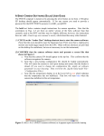
You can view the raw encoder position from the MCC GUI’s Details -> Pos screen. Here is a sample of the
‘APE & raw position values’:
The raw ape values are in Radians.
The Motor counts are the PMAC actual position (incremental encoder count values).
In MP mode, you can also position the TCS in unit of incremental encoder counts, using the MP.Cnt command.
For example, to move to 0 Ha and approximately 20 deg Dec do:
MP.cnt 0 1440000
(where 20 deg * 3600 deg/arc sec * 20 cnt / arcsec = 1440000 counts)
To move HA to 144000 (this is 10 rotation of the HA motor axis), and keep dec at ~ 20 degs.
MP.cnt 144000 1440000
Page 10
1201_Operators_Guide.doc
Version: 2014-12-03
7. Going beyond the software and hardware limits.
It important to remember the limit for the HA and DEC axis will trigger in the following order:
Software, slew, stop, brake, Hard. Also the Horizon limit are based on elevation.
Review Appendix C to understand how limits are handled in the TCS3.
If you hit a limit, for example software or stop. You can going MV mode and reverse directions to move away
from the limit.
You may need to travel beyond the limits. To do this you would need to disable the limit safety functions:
Software Limit Override is a checkbox on the MCC2 GUI. Check it to disable software limits.
Horizon Slew limits can be overridden on MCC2.
The Stop, Brake, and Horizon Stop limits can be overridden by tuning ON the Limit Override switch on
the TO Panel.
Once disable, you should be able to move to position beyond these limits.
8. Setting the Software Limits
Software limits are HA, and DEC limits within the software. They are used to prevent the operation from slew
the telescope beyond a established HA and DEC position. The default are:
HA:
Dec:
-05:35:00
-55:00:00
+05:35:00
+67:00:00
These limit can be changed using the command sw.limits.set command. The Daycrew is responsible for setting
the correctly TCS software limits, per instrument configuration. The procedure for setting the limit are as
follows:
1. As the user ‘to’ on the ‘t1’ computer, open an text editor to /home/to/current/ic/.tcs-init.
2. Within this file, you should lines such as:
# software limits used texes on 2012/01:
# sw.limits.set -05:34:00 05:34:00 -50:00:00 48:00:00
# normal software limits are:
sw.limits.set -05:34:00 05:34:00 -55:00:00 67:00:00
3. The ‘#’ are comments. Set the appropriate software limits, by uncommenting or adding the correct
values.
4. Restart the IC. Check the MCC Details->Position tab and confirm the software limits values are correct.
5. Email the IRTF Techgroup that the software limits have been changed.
Page 11
1201_Operators_Guide.doc
Version: 2014-12-03
9. The E100 Dome Servo System
In 2013, a new dome servo system based on the Baldor E100 Drives were installed at the IRTF. This sections
highlights key information the operators and daycrew should know in order to use or deal with the system.
A block diragram of the Dome Servo System is provide in T3-3040-Dome_cntl-Overview. You should be
familiar with the name, location, and function of the equipment. There is the PDF link:
http://irtfweb.ifa.hawaii.edu/~tcs3/tcs3/Design/T3-3040-Dome_Cntl-Overview.pdf
On MCC1, the Dome/Shutter area provides dome control and feedback for normal operations. If the a red
message appear indicating the Dome Servo is not ready, further troubleshooting is needed.
1. Insure SafetyBoard Error are cleared, System Power is on, and the TO Panel Dome switch is not locked.
2. More information on the Dome Servo E100 system can be viewed on the MCC’s Details Tab ->
DS/e100. The user manual 1101_MCC_GUI_and_TO_Panel document has some information on this
details screen.
3. The Dome-Servo-PC run the Baldor’s MINT Workbench software. This is a comprehensive Windows
application that provide full access to the E100 Drives. It does it all: Status Monitoring, Parameters
editing, Tuning, Data Collection, Driving Commissioning , and Application Development. A few good
things to know is including in the section.
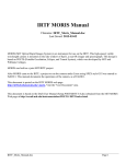
Workbench on the Dome-Servo-PC.
The dome-servo-pc is located in the TCS control room, next to the Dome Servo Electronic box. This desktop is
also accessible via VNC, ie “vncviewer dome-servo-pc:16000”. Use the project password.
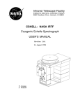
Normally there is 3 copies of the workbench running, one for each Drive. The workbench software
communication to the drives over the USB connection. If not, you can access the My_Mint shortcut on the
desktop, and run 3 workbench applications by double clicking on the .wbx for each node.
Page 12
1201_Operators_Guide.doc
Version: 2014-12-03
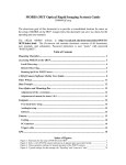
3 Workbench Applications running on the Dome-Servo-PC
Some vendor documentation is located here: http://irtfweb.ifa.hawaii.edu/~tcs3/tcs3/vendor_info/Baldor/
But workbench built in documentation, and it probably better to first use the Help system under workbench.
It is more complete and up-to-date that the electronic documents.
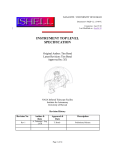
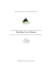
There is a screen shot of the workbench:
Above the tool bar, there is the green on black LED style node ID. There will be either ‘F0’, ‘01’, or ‘02’. This
identifies the controller’s ID that you are communication with. Be aware of this to insure to are accessing the
correct controller.
The toolbar has some icons where you can check on Errors. The green “No Error” Bar will be red when the
controller has errors. Click on error bar to display the error. The
should be press to keep appliation refreshed.
attemps to clear the error. And the
The Toolbox icon will change the middle area depending on the toolbox function selected. Many of the top
icons run wizards that configure various aspect of the system, like Connectivity, System Configuration, Drive
Setup, Operating Mode, AutoTune, FindTuning. These would be used only during initil setup, so avoid using
them.
Page 13
1201_Operators_Guide.doc
Version: 2014-12-03
Some toolbox function could be useful:
Edit&Debug – on Node F0, we run an mint application. This toolbox allow access window related to program
development. Becareful not to change the MINT program’s source code. The watch window is usefull to show
that the program is running. The Terminal window show console output of the program. And the Command
window allow you to interactively type MINT command to the controller.
Normally the progam should be running, I like to ‘check’ the parentTask that the MINT program is running and
when the dome is IDLE it is at or about line 100.
Scope – Using the Spy Window’s monitor tab, you could capture and graph data using the Scope Toolbox.
Parameter – All the controller parameters can be viewed from the parameter toolbox. Be very careful because
they can also be changed here too.
Errorlog – All error are log by the workbench. You can review past error here.
Clearing Errors
During operation if the Dome System stop due to error, It may be possible to clear the error and continue on
with operations.
Resetting the controller
Sometime when error happen, the program may be interrupted . You will need to reset the E100 Drive. This is
done by:
Locate the workbench for “F0”.
Reset the controller by hitting “Tool-> Reset Controller”.
Hopefully a 3 controllers will come up in an error free state.
Page 14
1201_Operators_Guide.doc
Version: 2014-12-03
10. The Hexapod Secondary
In 2013, a hexapod secondary was purchased, and put it into service. The TCS3 has the option of using the
chopper or hexapod secondary. The focus and collimation is controlled by the secondary. The hexapod has a
web page under the TCS3 located at: http://irtfweb.ifa.hawaii.edu/~tcs3/hexapod/. This site has a block
diagram. Everyone should be familiar parts of the system.
10.1 Setting up the TCS3 with the correct secondary.
When changing the secondary, the TCS3 need to be configure to work with the correct secondary. Edit this file
on the t1 computer: /home/to/current/ic/.tcs-init, and insure these lines are correct:
#
# set to chopper or hexapod
#
#secondary chopper
secondary hexapod
In the above example, the chopper is commented out using the ‘#’. The TCS3 is configured for the hexapod.
10.2 Initializing the hexapod
Before the hexapod can control the focus or collimation, it must be initialized. Go to the MCC GUI’s MCC tab
and select the Hexapod.Init button to initialized. This instructs the hexapod controller to home itself, and
should take about 1 minute.
10.3 Other things to know about the hexapod.
The hexapod has a Ethernet port. This port is reserved so that the vendor’s PC software can be used with the
hexapod. The IP/number of name for the hexapod controller at the summit is “irtf-hexapod”. The hexapod web
page above has a copy of the vendor’s CD containing all manual and software.
The TCS3 communicates with the hexapod using the controller’s RS-232 port. This port is connect to the
network using the digimim port 16.
The hexapod controller also has a keyboard and VGA port provide access to a simple GUI / Terminal. This can
be accessed via the network. Refer to the hexapod web page.
On the MCC Details FIOX screen, some Hexapod data is displayed. The TCS3 queries the hexapod about 4 Hz.
Position and Status information is provided. NS Collimation is the U axis. EW collimation is the V axis, and
Focus is the Z axis. Note the white lettering “Hexapod u=NS v=EW z=Foc”.
This table compares the Chopper and Hexapod units.
Page 15
1201_Operators_Guide.doc
Version: 2014-12-03
NS Collimation
Min
Max
Resolution
Hexapod
-4.00 deg
+4.00 deg
0.001 deg
EW Collimation
Min
Max
Resolution
-4.00 deg
+4.00 deg
0.001 deg
-4.80 v
+8.00 v
0.010 v
Focus
Min
Max
Resolution
-8.00 mm
+8.00 mm
0.005 mm
-7.32 v
+7.00 v
0.005 v
According to M.Connelly:
0.142 degrees = 1v
1.7737mm = 1v
Page 16
Chopper
-9.00 v
+4.06 v
0.010 v
1201_Operators_Guide.doc
Version: 2014-12-03
11. TCS3 and JPL Horizon ephemerides data.
The TCS3 accepts tracking data in the following coordinates system.
FK5/Any Equinox (FK5/J2000.0 is the default, which is the ICRF).
FK4/Any Equinox (FK4/B1950.0 is the default)
APP - Topocentric Apparent RA and DEC.
Includes Light deflection, annual aberration, Precession and nutation. And refraction.
TCS3 displays the Azimuth and Elevation values in Topocentric Apparent.
When using ephemerides, your best option is to use an Astrometric ICRF RA & DEC,
which is the same as FK5 J2000.0.
1. Using JPL Horizon Astrometric RA & DEC (Highly recommended).
Horizon:
Your location should be Mauna Kea [568].
Select the ICRF/J200.0 format (Horizon's default).
Select Rates, RA & DEC
Enter Rates as nonsidereal rate (divide by 3600 to convert from "/hr to "/s).
For TCS3,
set CS=FK5, EQ=2000.0, EP=2000.0 (also TCS3's defaults).
Enter RA, Dec and non-sidereal rates.
2. Using JPL Horizon Apparent RA & DEC (not recommended).
Horizon:
Your location should be Mauna Kea [568].
Select Apparent RA & Dec
Select Rates, RA & DEC
Select the "standard atmosphere refraction model" option.
Enter rates as nonsidereal rate (divide by 3600 to convert from "/hr to "/s).
For TCS3,
set CS=APP.
Enter a-apparent RA, Dec from Horizon
Enter Rates as nonsidereal rate (divide by 3600 to convert from "/hr to "/s).
(All Topocentric Apparent object will need a tracking rates).
Page 17
1201_Operators_Guide.doc
Version: 2014-12-03
12. How to update the collimation table.
1. Open a text editor and edit the /home/to/data/collimate.txt file
On the t1 computer, start gedit by clicking on the Application -> Accessories -> Text Editor menu.
2. Open the collimation file.
In gedit, open the file HOME/data/collimate.txt
3. Edit
To preserved a history of the collimation data, copy the current values, and comment them out by
placing a ‘#’ in front of the lines.
Edit the values.
Save the file
Quit gedit.
4. On the TCS MCC, type the follow in the command line interface to reload the new values in the TCS.
collimate.table.read
then hit return
Page 18
1201_Operators_Guide.doc
Version: 2014-12-03
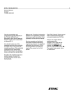
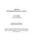
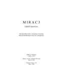
13. Focus Adjustment Graphs
The tcs calculates a focus adjustment value based on change of temperature and position. The is done in the
TCS focus loop with run at 10Hz. The adjustment formulas used are from the following documents:
IRTF Focus vs. Temperature, Michael Connelley, Apr 8 2011
http://iborg.ifa.hawaii.edu:8080/Plone/irtf-projects/image-quality/Focus_temp.pdf/view
Mapping IRTF's Focus Shift vs. Pointing, Micheal Connelley, Apr 19 2011
http://iborg.ifa.hawaii.edu:8080/Plone/irtf-projects/image-quality/Focus_Pointing_Mapping.pdf/view
Here are graphs showing the focus changes based on temperature and position. This data was taken using the
IRTF Chopping Secondary, thus the focus units are the LVDT voltages.
Page 19
1201_Operators_Guide.doc
Version: 2014-12-03
14. Misc Problems and Solutions
1. No Sound from the speakers
The OS is not very reliable with configuring the sound. If the sound is not present, do the following:
1. Check the power & volume setting on the speakers.
2. In an xterm, run the system-config-soundcard program. Normally, just selecting the Play test sound
button seem to get thing working.
2. What to do if the tracking exits and goes back to STOP mode?
Something the PMAC terminates the PID loop, and the TCS go back to Stop mode. If this happens, just restart
tracking. You will have lost your position since while the stop mode wipes out your base and target position. So
just re-slew back to your object.
3. What to do if the slew doesn’t slew, or the MP, MV commands don’t seem to execute. Or the PMAC
doesn’t seem to be accepting the move commands.
Remember that the PMAC is a computer. The TCS3 is basically one computer talking to another computer.
Sometime this communication doesn’t happen. In the case of the slew, not slewing. Try the ‘ReSlew’ button .
This this doesn’t work, go back to tracking, and re-issue the slew request.
In the case of MP, MV reissue the commands. Sometime you may need to go back to STOP and reenter the
MV or MP mode.
I’ve seen the PMAC just not respond. In this case.
Goto Stop mode
On MCC3, issue the PMAC.Reset($$$) button.
Type ‘die’ in the MCC to kill the IC.
Restart the IC and MCC.
If this don’t help, then to a cold boot of the system:
Goto Stop mode
Do a cold boot of the t1 computer (use the ‘poweroff ‘command as root).
Power on the PC after 10 seconds.
Start the TCS3 software.
4. NAN is displayed on the MCC on some of the position values.
The NAN is illegal floating point number, ie "Not A Number". Mostly like a software bug, until I track it down,
TO's should restart the IC:
1. To help me debug this take a screen capture with the
mcc in Details->Pos and Pointing. See example:
http://irtfweb.ifa.hawaii.edu/~denault/others/Screenshot.png
Page 20
1201_Operators_Guide.doc
Version: 2014-12-03
(screen shot can be made using 'Actions->Take Screenshot' menu on T1.
2. Goto Stop mode. (take note of your madj values).
3. Type 'die' to kill the IC & MCC.
4. Restart the IC and MCC.
5. Goto Zenith, In Stop mode, do a ape.reset.pmac.
6. Resume operations.
Page 21
1201_Operators_Guide.doc
Version: 2014-12-03
Appendix A – Block Diagrams of the TCS3 control system.
A block diagram of the tcs3 control system is maintained http://irtfweb.ifa.hawaii.edu/~tcs3/tcs3/Design
The staff should be familiar with the TCS3 at this level. A of the block diagram is displayed here for reference.
Page 22
1201_Operators_Guide.doc
Version: 2014-12-03
It is also important to identify and understand the key components of the servo system.
1. The Virtual TCS (VTCS) is a software process running at 20Hz, it calculates the mount position to
observe a sky object. The Real TCS (RTCS) is another software process, it takes the mount position and
commands the motor controller to follow a trajectory to track the sky object.
2. The PMAC is a PID-based motor controller. It is a PCI slot peripheral board located inside the T1 PC. It
is commanded by the RTCS and is the servo controller for the TCS3. Each PMAC axis (HA and Dec) is
configured to driver 2 DAC for the IRTF’s dual motor configuration. For position feedback, an
incremental encoder on the bull gear is used. For velocity feedback, the analog signals from each
tachometer motor is averaged by the safety board and provide to the PMAC.
3. The Safety board is a custom built IRTF elelctronic board. It has 2 primary functions, the TAC feedback
loop, and the safety function:
a. A feedback loop for each motor is performed. The DAC output from the PMAC is conditioned
before being applied to the amplifiers based on the tachometers for that motor. The 2
tachometer signals are also average and provide to the PMAC a its velocity sensor input.
b. Various inputs are monitors by the safety function circuits. These signal can trigger a shutdown.
When alerted the safety board will display the amplifiers and apply the telescope brakes.
4. Fioe is an opto22 data acquisition device. It samples various signals related to the servo system and
safety board. The TCS3 application monitors this device, and will alert the operator when a safety
condition has occurred.
Page 23
1201_Operators_Guide.doc
Version: 2014-12-03
Appendix B – The Position Table, Mean-to-Mount Calculations
The Position Table:
During tracking operations, the target TCS position is controlled by the position table. Here is an illustration of
the information in the position table:
CS FK5
Name
User
Beam
Scan
TotalOS
OS.enable
off
off
off
Target
Proper motion
RA (s/yr)
Dec(as/y) Equinox
0.000
0.000
2000.00
Base
19:49:34.39 20:28:19.2
OffSets (as)
0.00
0.00
0.00
0.00
0.00
0.00
0.00
0.00
NS Rates
(as/s)
0.000000
Epoch
2000.00
0.000000
Scan Dest (as)
Time(sec)
0.00
0.00
0
19:49:34.39 20:28:19.2
Base Position:
CS is the Coordination System, which can be FK5, FK4, and Apparent. Related commands are:
o cs { fk4 | fk5 | app }
The Base provides the RA, Dec position. Proper motion defines the space motion of the BASE RA,Dec .
Related commands are:
o Base RA(hr) Dec(deg) [ra_pm (sec/yr) dec_pm (as/Yr) Ep Eq CS]
o Base.inc ra(as) dec(as)
Equinox is the cataglog equinox of the coordinate system. Epoch is the chronological references for the
position. For FK5, the standard equinox and epoch are usually 2000.0. For FK4, they are 1950.0. For
apparent, the equinox is not used, but the epoch dates the apparent coordinates. In most cases, when
using apparent, set the epoch to the current julian epoch (Jan 01, 2010, would be Epoch 2010.0)
Related commands are:
o Epoch Yr
o Equinox Yr
NS rates allow you to track non-sidereal object.
o ns.rate ra(as/s) dec(as/s)
o ns.rate.inc ra(as/s) dec(as/s)
Off Sets:
The user and beam are both general purpose user offsets. It is suggest using UserOS for dithering and offsets,
and BeamOS for Beamswitching. Related commands are:
o Beam.set ra(as) dec(as)
o Beam.clear
o Beam.inc ra(as) dec(as)
o Beam.on or Beam.B
o Beam.off or Beam.A
o Beam.toggle
o User.set ra(as) dec(as)
Page 24
1201_Operators_Guide.doc
o
o
o
o
o
Version: 2014-12-03
User.clear
User.inc ra(as) dec(as)
User.on
User.off
User.toggle
Scan is a special case offset, for scan across a target. Related commands are:
o Scan.set ra(as) dec(as) duration(sec)
o Scan.go
o Scan.return
o Scan.clear
Target Position
The base + offset are summed to produce the target position. This is the sky position the telescope the pointing
at.
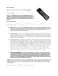
Mean to Mount Calculation Summary – It is important to understand the basic terms to describe position.
The following diagram illustrates the terms and how the astronomical coordinates are transformed in TCS3.
Page 25
1201_Operators_Guide.doc
Version: 2014-12-03
Page 26
1201_Operators_Guide.doc
Version: 2014-12-03
Appendix C – Telescope HA, Dec, Horizontal Limits
The follow types of limits exist in the TCS:
Software limits – Software Limit to limit the commanded position of the TCS. Handled by software.
Slew limit – hardware limit to limit max velocity from slew to tracking rates. Handled by software.
Stop limit – hardware limit. Handled by the Safety Board.
Brake limit – hardware limit to indicated emergency condition. Handled by the Safety Board.
Horizontal slew limit – A hardware limit. Handled by software.
Horizontal stop limit – A hardware limit. Handled by the Safety Board..
Speed limit – Internal position if passed, the software will reduce the velocity to tracking velocity. Handled by software.
Hard limit – Internal variables in the TCS3 software. RTCS will not command movement pass this limit. Handle by software.
Hardware safety limits (Stop, Brake, Hor Stop) can be overridden by the limit override switch on the TO Panel.
Software limits (Software, Hor Slew) have off/on toggle buttons on the GUI.
Speed, Hard cannot be overridden.
Summary of Limit Logic
TRACK
SLEW
MP
MV
STOP
Software
Stop movement
End Slew.
Stop movement
Stop movement
N/A
in the direction of Goto STOP
in the direction of in the direction of
limit. Goto STOP mode.
limit.
limit.
Slew
N/A
Reduce speed to
Reduce speed to
Reduce speed to
N/A
tracking rates.
tracking rates
tracking rates.
Stop
Stop movement
End slew.
Stop movement
Stop movement
N/A
in direction of
Goto STOP
in the direction of in the direction of
limit. Goto STOP mode.
limit.
limit.
Horizontal Slew
(19 Deg)
N/A
Reduce speed to
tracking rate
Reduce speed to
tracking rates
Reduce speed to
racking rates
N/A
Horizontal Stop
(10 Deg)
Stop tracking.
Goto STOP
End slew.
Goto STOP mode
Exit track mode.
Goto STOP
mode.
N/A
Exit Slew.
Goto STOP
mode.
Reduce speed to
tracking rate.
Stop movement
in the direction of
limit.
Stop movement
in the direction of
limit.
Reduce speed to
tracking rates.
N/A
Brake
Stop movement
in the direction of
limit.
Stop movement
in the direction of
limit.
Reduce speed to
tracking rates.
Stop movement
in direction of
limit. Goto
STOP.
End Slew.
Goto STOP
Mode
Stop Movement
in direction of
limit.
Stop Movement
in the direction of
limit.
N/A
Speed
Hard
EAST -HA
WEST +HA
SOUTH -DEC
NORTH DEC
Speed
Slew HW (est)
-05:15 hrs
05:15 hrs
-50:00 deg
60:00 deg
-05:27 hrs
+05:28 hrs
-53:07 deg
+62:00 deg
Table of Limit Values
Software
Stop HW (est.)
-05:35 hrs
+05:35 hrs
-55:00 deg
+67:00 deg
Hor Slew Limit is 70.0 deg (est).
Hor Stop Limit is 75.0 deg (est).
Page 27
-05:38 hrs
+05:36 hrs
-56:42 deg
+67:19 deg
Do not exit STOP
mode.
N/A.
Brake HW (est)
Hard
-05:57 hrs
+5:57 hrs
-59:28 deg
+69:38 deg
-06:00 hrs
+06:00 hrs
-65:00 deg
+70:15 deg
1201_Operators_Guide.doc
Version: 2014-12-03
Appendix D – List of MCC Errors and Warnings Notices
On mcc1 the warning window can display the following errors and warning messages. Appendix C further
describes these messages. There are 3 type of Notices.
1. Error notices – are displayed in Red. These are problem most serious in nature.
1. Safety Board Errors Exist – A error condition exist on the t3 servo electronic safety board. The condition
must be cleared in order to allow tcs3 servo operations.
2. Stop or Brake Limit Set – Physical limit switches on the HA and Dec axis, or Horizon limit have been
tripped. These are axis limit switches.
3. PMAC IO Error – The tcs3 software was not able to communicate with the PMAC motor controller. To
clear the condition: 1)Retry the operation. 2) restart the tcs3 IC. 3) reboot the tcs3 computer. 4) Call for
technical assistance.
4. PMACTimestamp Error – This indicated the software loops in the PMAC motor controller are not
executing. To clear the condition: 1)Retry the operation. 2) restart the tcs3 IC. 3) reboot the tcs3 computer. 4)
Call for technical assistance.
5. APE – Motor Apos > 600”
6. APE – Motor Apos > 600” - The APE position differ from the Incremental Encoder Position (IPE) by
more that 600”. Make sure the APE are working, and try re-setting the APos (using APE.SET.PMAC with the
telescope in STOP mode at Zenith).
2. Warning Notices are less serious errors or message that indicate a condition the operation should be
aware of. They are display in Yellow.
9. Using sim motors(CF_PMAC=0) – The software has be compiled to using simulated software motor. This
is a engineering mode and should never be seen for IRTF operations.
10. Hardware Limit Override On – The hardware limit override switch on the TO Panel is ON.
11. Software Limit Override On – The software limit override (in mcc2) is ON.
12. System Power is off – The system power is off.
13. Hardware Slew Limit set – The hardware slew limit switch is ON.
14. Software Limit reached - The software limit position has been reached.
15. Dome blocking FOV – The Dome and Telescope Azimuth position differ by more that 2 degrees, thus the
telescope’s field of view may be blocked.
16. MirSup Warning - Kill Err - The mirror support that a KILL signal indicating a hardware fault has
occurred. The KILL signal is true.
Page 28
1201_Operators_Guide.doc
Version: 2014-12-03
17. MirSup ON & Volt Low - The mirror support is on, but the voltage used to indicate pressure is close to
zero (indicating no air pressure).
18. Counterweight(s) are stuck – While moving a counterweight, the position did not change after a few
seconds, thus it is stuck. Maybe you reached the end of travel or some other failure occurred.
19. Focus is stuck - While moving the focus, the position did not change after a time interval, thus it is stuck.
Maybe you reached the end of travel or some other failure occurred.
20. Collimate is stuck - While moving the collimated motors, the position did not change after a time interval,
thus it is stuck. Maybe you reached the end of travel or some other failure occurred.
21. APE data is stale ( >2 sec) – The ape are polled for new position at an interval greater that 5Hz. A new
position was not received for more that 2 second, indicating a communication problem between the tcs3
comptuer and the ape computers (t3apeha or t3apedec).
22. Dome pos. data is stale (>2 sec) – The dome position is sent to the the tcs3 via a serial stream. The
dome_scanner ouput is feed into the fio_a opto22 serial module. The update rate is about 2 Hz. Thes message
indicated no new data was received within 2 seconds. Further investigation is needed.
23. ZenDist large, refra. disabled. – When the zenith distance is > 85 degress, the refraction calculation is
disabled. This is because large zenith distance requires a huge amount of cpu time, and after this zenith
distance it will soon overwhelm the computer.
24. Humidity limit exceeded – The humidity exceeds the limit set by the humidity.wn command.
25. FIO_A is off line – The opto22 device whose hostname is t3fioa is offline.
26. FIO_B is off line - The opto22 device whose hostname is t3fiob is offline.
27. FIO_C is off line - The opto22 device whose hostname is t3fioc is offline.
28. FIO_D is off line - The opto22 device whose hostname is t3fiod is offline.
29. FIO_E is off line - The opto22 device whose hostname is t3fioe is offline.
30. FIO_F is off line - The opto22 device whose hostname is t3fiof is offline.
31. FIO_MC is off line – The RIO device whose hostname is t3fiomc is offline.
32. FIO_ape HA comm error – There was an error communicating with the fio_ape computer, hostname
t3apeha. Check the embedded APE computer for HA.
33. FIO_ape Dec comm error - There was an error communicating with the fio_ape computer, hostname
t3apedec. Check the embedded APE computer for DEC.
34. Bad AIO on FIO_A
35. Bad AIO on FIO_B
36. Bad AIO on FIO_C
Page 29
1201_Operators_Guide.doc
Version: 2014-12-03
37. Bad AIO on FIO_D
38. Bad AIO on FIO_E
39. Bad AIO on FIO_F – FIO A,B,C,D,E, and F are opto22 device. They have Analog In modules have can go
bad. This TCS warning indicate the software see ‘bad Analog In’ values on a module. It is likely the module
need to be replaced. Day Crew and TCS support staff need to be consulted. Details tab on MCC may help you
determine which module is bad… but sometime the 1st analog module on the opto22 bus can cause the other to
report bad data.
40. PMAC following Err – The following error in the pmac exceeds 1800 arcsec ( 0.5 degrees).
41. SafetyBrd_OS_Ha_Latch - The T3 Safety Board’s Over Speed HA Latch is TRUE.
42. SafetyBrd_OS_Dec_Latch - The T3 Safety Board’s Over Speed Dec Latch is TRUE.
43. SafetyBrd_OC_West_Latch - The T3 Safety Board’s Over Current West Latch is TRUE.
44. SafetyBrd_OC_East_Latch - The T3 Safety Board’s Over Current East Latch is TRUE.
45. SafetyBrd_OC_North_Latch - The T3 Safety Board’s Over Current North Latch is TRUE.
46. SafetyBrd_OC_South_Latch - The T3 Safety Board’s Over Current South Latch is TRUE.
47. SafetyBrd_OC_Dome1_Latch - The T3 Safety Board’s Over Current Dome Motor 1 Latch is TRUE.
48. SafetyBrd_OC_Dome2_Latch - The T3 Safety Board’s Over Current Dome Motor 2 Latch is TRUE.
49. SafetyBrd_OC_Dome3_Latch - The T3 Safety Board’s Over Current Dome Motor 3 Latch is TRUE.
50. SafetyBrd_Emerg_Stop_Latch - The T3 Safety Board’s Emerg Stop Latch is TRUE.
51. SafetyBrd_DomeHP_Stop_Latch - The T3 Safety Board’s Dome Hand Paddle Stop Latch is TRUE.
52. SafetyBrd_Mtr_Cntr_Err_Latch - The T3 Safety Board’s Motor Controller Err Latch is TRUE.
53. SafetyBrd_PC_Lockout_Latch - The T3 Safety Board’s PC Lockout Latch is TRUE.
54. SafetyBrd_HA_Stop_W_Latch - The T3 Safety Board’s West Stop Limit Latch is TRUE.
55. SafetyBrd_HA_Stop_E_Latch - The T3 Safety Board’s East Stop Limit Latch is TRUE.
56. SafetyBrd_HA_Emerg_W_Latch - The T3 Safety Board’s West Emergency (or Brake) Limit Latch is
TRUE.
57. SafetyBrd_HA_Emerg_E_Latch - The T3 Safety Board’s East Emergency (or Brake) Limit Latch is
TRUE.
58. SafetyBrd_Dec_Stop_N_Latch - The T3 Safety Board’s North Stop Limit Latch is TRUE.
59. SafetyBrd_Dec_Stop_S_Latch - The T3 Safety Board’s South Stop Limit Latch is TRUE.
Page 30
1201_Operators_Guide.doc
Version: 2014-12-03
60. SafetyBrd_Dec_Emerg_N_Latch - The T3 Safety Board’s North Emergency (or Brake) Limit Latch is
TRUE.
61. SafetyBrd_Dec_Emerg_S_Latch - The T3 Safety Board’s South Emergency (or Brake) Limit is TRUE.
62. SafetyBrd_Horizon_Stop_Latch - The T3 Safety Board’s Horizon Latch is TRUE. The telescope is tipped
over to far. ( Hardware switch turns on when zenith distance is > 75 degrees).
63. SafetyBrd_Watchdog_Tmr_Latch - The T3 Safety Board’s Watchdog Timer Latch is TRUE.
64. SafetyBrd_Clocking_Error_Latch – The T3 Safety Board’s internal clock monitor has indicated a
clocking or timeout error. This is an internal safety board error.
65. SafetyBrd_Dome_Amp_Enable_Therm – This error indicate there is a problem with the Enable Line or
the Thermal Fuse on the Dome amplifiers. Try the Thermal Fuse Reset button on Dome Amplifier, else contact
the Daycrew or IRTF EE.
66. SafetyBrd_Tel_Amp_Enable_Therm – This error indicate there is a problem with the Enable Line or the
Thermal Fuse on the Telescope amplifiers. Stop the telescope, and turn off power. Contact the TCS3 support
engineer.
67. SafetyBrd_Spare1 – A spare input on the safety board has triggered. This shouldn’t happen. Contact the
TCS3 support engineer.
68. SafetyBrd_Spare2 – A spare input on the safety board has triggered. This shouldn’t happen. Contact the
TCS3 support engineer
69. SafetyBrd_Tach_Switch_is_off – An internal switch on the safety board used to enable the tachometer
feedback loop is OFF. The switch need to be turned on when operation the IRTF Summit Servo system. (It is
off, when running in the Hilo test system).
70. PowCntl&Brakes Err(FIOE) – FIOE monitors the HA and Dec Brake _Enable (to control the breaks) and
a _Sense line to confirm the start of the brakes. These signals to not match. Call IRTF superintendent or IRTF
EE. Also check the status on MCC->Details->FIOE.
71. Crane not stowed – The dome crane is not stowed.
72. TOP Tele Enable is OFF – The TO Panel’s Telescope Enable switch is OFF.
73. Mir Cover open & Cooling on – The Mirror Covers are open and the Mirror Cooling is ON.
74. Check T3 P/S (in mcc3 GUI) - The power supplies being monitored by FIOA/B have a > 5% error.
Further investigation is required. Check the MCC GUI to identify the power supply triggering the error.
75. Check Closed Cycle Coolers – The closed cycle cooler warning signal is ON. Coolers may have tripped
off.
Page 31
1201_Operators_Guide.doc
Version: 2014-12-03
76. Dome may be Stalled – The DAC (motor command) to the dome amplifiers is 2 volts or greater, but the
dome velocity from the bar code sensor indicates not position change.
77. Monitor Mirror Cooling – The Operator should check or monitor the mirror cooling system. There may be
an error in the system, or it is operating in a unusually mode You can check on the mirror cooling IO setting via
the MCC Detail Tab. View the FIO_MC details.
78. Approaching Lower Shutter – The tcs3 thinks you are getting close to the lower shutter.
79. Check TAC& Mtr Vel Data – The data on the velocity sensor don’t match. The velocity sensor are the
velocity voltage from the tachometer (out of the safety board), and the incremental encoders.
80. PMAC PID not optimal – You do not have the correct PID value loaded in the PMAC controller. This can
degrade servo performance while tracking/Observing. There are 2 way to fix this:
1. Exit tracking mode (either STOP to Re-Slew to target), and resume tracking.
2. Use MCC3 Engineering Option to reload Tracking PID while observing:
1. Goto MCC3’s Engineering Options Tab
2. Check ON the “ServoOpt.Enable” check button. (The Enable the servo engineering and PID option on
MCC3).
3. Click the “Ld.Trk” botton on the PID frame in MCC3. (This will reload the tracking PID to the PMAC).
4. Check OFF the “ServoOpt.Enable” check button.
81.AMP Power Warning (FIOB) - The system power is ON, but voltage to the servo amplifiers indicate there
could be a problem. HA, Dec, and Dome AMPs require > 60 volts from the Power Supplies, check MCC GUI > Details -> FIOB screen for AMP power supply voltages.
82. Motor Currents High – If any of the motor currents (East, West, North, South, Dome1, Dome2, Dome3)
exceed some normal operational value this message and a audio warning will occurred. Quickly access the
situation to insure the telescope or dome isn’t stuck or impeded.
83. IQUP Data is Stale – The TCS3 gets some facility data (temperature, wind speed) from the IQUP system.
This warning indicates some IQUP data is stale. Go to the Details -> FOX tab, and review the IQUP data.
The details show the timestamp of the data, normally data is taken at 180 or 360 second intervals or less.
Disregard any stale data, and report the problem to the technical staff.
84. High Wind Warning – A notice warning with sound alert should trigger when the wind speed exceed the
high wind warning level, normally set at 35mph.
85. Machine Room is Hot ( > 80 deg F) – The iqup sensor TMR5 is sample by the tcs. When the temperature
exceeds 80 deg, then this warning appears. Operators/Staff should address the situation. Open the machine room
door and use the fan to cool the room.
86. DS/e100 data stale (check details)
87. DS/e100 has errors (check details)
The DS/e100 refers to the Baldor E100 Dome Servo Drive system. The message indicate an issue with the servo
system. Please review the Details ->DS/e100 tab. After reviewing the tab, hopefully a better assessment of the
state of the dome servo could be provided. Also section 8. The E100 Dome Servo System, has some
instructions on using the Baldor Workbench Software to assist with trouble shooting any Dome Servo System
issues.
Page 32
1201_Operators_Guide.doc
Version: 2014-12-03
88. Hexapod has errors (check details FIOX) – Please review the Details Misc tab’s Hexapod information.
There is an issue with the hexapod. Also review section 9. The IRTF Hexapod Secondary, has some
information operation the hexapod.
3. Sound notices are audio message play via the computer’s speaker output. Usually they are self explanatory.
completing slew – slew has reach its destination.
sm_stop – Entering Stop Mode.
sm_mp – Entering MP mode.
sm_mv – Entering MV mode.
sm_track – Entering track mode.
sm_slew – Entering slew mode.
sm_error_exiting – TCS is existing a servo mode due to an error.
system_power_off – The system power has been turned off.
humidity_rising
humidity_falling –The humidity crossed the warning point (falling or rising).
next_obj – The tcs has received a new data in its slew next buffer (sound is a bee-boo).
upper_shutter_up – Upper shutter limit turned ON.
shutters_touch – Shutter touch limited turned ON.
lower_shutter_dn – The lower shutter limit turned ON.
approaching_lower_shutter – You are getting near the lower shutter.
Can’t do please check –Operator can’t start the servo if the system power is off or safety board error exist.
start data recorded – audio freed back with pt.star.add is done.
dome is ready – When tracking the dome has lined up with the telescope.
move completed – The MP move has reached it destinations.
Brakes are set– TCS tells you when brake are engaged.
Beamswitch – A sound plays when a beam switch occurs.
Please reslew – Trying to slew, but velocity is 0. Operators needs to press the reslew button on the mcc1 GUI.
Last_Pointing_star – or “Completed pointing pattern” when the last star in the pointing pattern is recorded.
Motor Currents High – Check the TCS3 motor currents for the HA, DEC, and Dome motors.
High Wind Warning – Winds speed is above the high wind warning limit, normally 35mph.
Page 33