1
IRTF MORIS Manual
Filename: IRTF_Moris_Manual.doc
Last Saved: 2015-03-02
MORIS (MIT Optical Rapid Images System) is an instrument for use on the IRTF. This high-speed, visible
wavelength camera is mounted on the side window of SpeX, a near-IR imager and spectrograph. This design is
based on POETS (Portable Occultation, Eclipse, and Transit System), which was developed by MIT and
Williams Colleges.
MORIS was built as a joint MIT/IRTF project.
After MORIS came to the IRTF, a project to run the camera under Linux using SPEX style GUI was started in
Feb2011. This manual documents the operations of the camera, as of Feb2011.
This document is posted on the IRTF MORIS web page:
http://irtfweb.ifa.hawaii.edu/~moris. Visit the “User Document” area.
This document is based on the Draft User Manual (Setup.POETSIRTF.3.0.doc) obtained from the MIT MORIS
Web page at http://occult.mit.edu/instrumentation/POETS/ IRTF/index.html.
IRTF_Moris_Manual.doc
Page 1
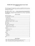
Table of Contents
Figure 1 – Moris Block Diagram .......................................................................................................................... 3
1. A quick Intro into Moris .................................................................................................................................... 4
2. Moris Windows ................................................................................................................................................... 5
2.1 Accessing the Moris Windows Desktop .................................................................................................................... 5
2.2 Solis Notes .................................................................................................................................................................... 6
2.2.3 Filter Wheel’s SMGUI .......................................................................................................................................... 10
2.2.4 Data Transfer ......................................................................................................................................................... 11
3. Moris Linux ...................................................................................................................................................... 12
3.1 Accessing Moris Linux ............................................................................................................................................. 12
3.2 Initializing the iXon Camera. .................................................................................................................................. 14
3.3 Simple Observing Instructions for Linux ............................................................................................................... 15
3.4 Guiding ...................................................................................................................................................................... 16
3.5 Movie Mode ............................................................................................................................................................... 16
3.6 Setup Tab................................................................................................................................................................... 18
3.7 Macro Tab ................................................................................................................................................................. 18
3.8 GPS Tab..................................................................................................................................................................... 19
Appendix A – Staff Start up Procedures for Moris............................................................................................. 20
Appendix B - Mounting Checklist ...................................................................................................................... 22
Appendix C – Filter Wheel Details ...................................................................................................................... 23
Appendix D - Fore-Optics and Mounting Box notes .......................................................................................... 24
D.1 - Adjustment of the z-extension .............................................................................................................................. 24
D.2 Adjustment of mount for lenses 2 & 3 ................................................................................................................... 24
Appendix E – Movie Mode Timing...................................................................................................................... 25
Appendix F – Additional notes ............................................................................................................................ 27
E.2 -Cooling ..................................................................................................................................................................... 27
E.3 PCI interface............................................................................................................................................................. 27
E.4 Trigger cable............................................................................................................................................................. 27
E.5 GPS ............................................................................................................................................................................ 27
Appendix G – Problems and Solutions................................................................................................................ 28
IRTF_Moris_Manual.doc
Page 2
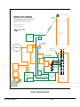
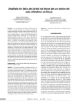
MORIS BLOCK DIAGRAM
GPS antenna
on telescope
* Reimage optics provide 60x60 arcsec FOV with paraxial
working f/# of 9.32 and pixel scale of 0.12"/pixel
GREEN = supplied by MIT
ORANGE = supplied by IRTF
AC Power Symbol
Telescope
Spectrum Instrument
TM4 GPS Unit
Ethernet
Digi One
“morisdigi”
128.171.165.61
Network
P/S
P/S
Spexpwr, outlet 8
“moris_camera”
Manual shutter
for SpeX window
RS-232
Anamatic Power
Supply
Mounting Box
Dichroi c
Anamatic
Motor
Keyboard
Video Mouse
Adder iPEPS
IP KVM
“”moriskvm”
128.171.165.59
Com1
Computer
Camera Pwr
Supply
Camera power cable
(6' to adapter, 6.6' after adapter)
Externa trigger (20' BNC-SMB)
Camera PCI board
CCI-23
P/S
Kvmcass replaced
“moriskvm” in 2014/12.
moriskvm/Adder still
located in coolracks
(Reimaging
optics* + filter
wheel)
Ethe rnet
kvmcass
Port 2
Andor Camera
Ixon DU-897E
PC-camera cable ( 6m, 36-pin)
Spexpwr, outlet 7
“moris_PC”
FIGURE 1 – MORIS BLOCK DIAGRAM
IRTF_Moris_Manual.doc
Page 3
SpeX
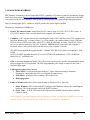
1. A QUICK INTRO INTO MORIS
MIT Planetary Astronomy Labs developed the POETS, a portable CCD camera system for Occultation, Eclipse,
and Transit observations (http://occult.mit.edu/instrumentation/poets.php). A modify system built for the IRTF
was constructed by the MIT and IRTF. This system is called MORIS (MIT Optical Rapid Imaging System).
Moris is mounted onto SpeX. A dichroic in SpeX provides the optical light to MORIS.
The primary components of MORIS are:
1. Ixon CCD Camera System: Andor IXon DU-897 camera, using a 512x512 E2V CCD97 sensor. A
CCI-22 PCI interface card is used to interface the computer and camera unit.
2. Computer: A PC runs the software for controlling the camera, GPS, and filter wheel. This computer can
boot in to Windows XP or Linux (Centos 5.x). Using window, the vendor software for the CDD and
GPS, as well as a IRTF written filter wheel GUI, is used for observing. In Linux, a SpeX like GUI (ic,
xui. Dv) is used for observing. The irtf’s “kvmCass” IP KVM unit is connected to the computer’s
keyboard, mouse, video port to allow network access to the computer’s console.
The MIT Group supplied the orginal PoetsPC. A Shuttle XPC SB61V40. (dual-core Pentium D, 2GB
RAM).
In 2012, the IRTF upgraded the moris PC to a GA-B75M-D3H motherboard, i3 CPU, 8GB RAM
housed in a 19” rackmount case.
3. GPS: A Spectrum Instruments Model TM-4 GPS system can be used to provide a programmable output
pulse to trigger the CCD acquisition. The GPS Programmable pulse output is connect to the iXon’s
external trigger input.
4. Light-tight Foreoptics box contains:
Filter Wheel: A cuctom-built wheel with ten 1” filters. Motorized using a Animatics
Smartmotor connected to the LAN via a DigiOne Terminal server.
Fold Mirror: protective silver coathing (>90% reflectivity).
Reimaging optics:
5. Linux or Windows OS. Moris can be used in either its Window OS, or linux OS.
a. Moris Windows - The Camera and GPS vendor provide Windows software for controlling the
hardware. This is the software used by the POETS systems.
b. Moris Linux – A IRTF GUI has been developed to run MORIS with an software interface
similar to SpeX.
Prior to observer you should request either the Window or Linux environment so MORIS can be setup
properly for you. The staff can help you switch the OS, if needed (See Appendix A).
IRTF_Moris_Manual.doc
Page 4
2. MORIS WINDOWS
Using window, MORIS is operated using 3 separate applications:
Andor Solis 4.8.3.0 – The vendor’s software for the IXon CCD camera.
Spectrum TM-4 Control Software – for the GPS unit.
SMGUI – an IRTF Smart Motor GUI for controlling the filter wheel.
2.1 Accessing the Moris Windows Desktop
1. Prerequisites
For summit users, you will need an IRTF guest account.
For remote users, you will need a vnc viewer.
Refer to http://irtfweb.ifa.hawaii.edu/observing/remote_obs/ for accounts and VNC information.
2. For summit observers:
Login to Stefan using your guest account.
From an xterm, run the vnc viewer: “vncviewer moris”. (password is “irtfirtf”).
3. For remote observers:
Connect to the vnc session “stefan.ifa.hawaii.edu:12” via you VNC viewer application. Contact the
TO or IRTF staff for the VNC password of the day.
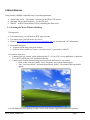
Connect to the window desktop using vncviewer inside the Stefan:12 vnc session:
o Click on the work space menu, select “Programs” and a xterm should appear.
o Type “vncviewer moris”, and enter the password “irtfirtf”. The window desk top should
appear.
4. On the Right side of the desktop you have access to the window applications that make up moris:
IRTF_Moris_Manual.doc
Page 5
Spectrum TM-4 Control Software – Vendor application for the GPS unit.
Andor Ixon – Data acquisition software for the Ixon Camera is Solis.
Smgui.bat Filter Wheel – GUI for selecting the filter.
Plus other helpful applications.
WinSCP – Feee SFTP, SCP and FTP client. Installed by MIT.
SSH Secure Shell/SSH Secure File Transfer – IRTF preferred ssh and sftp clients.
2.2 Solis Notes
A User Guide to the Andor Ixon Camera can be access via the MORIS web site. Here are some simplified
instruction for camer operations.
Because there is currently no other location in this document for this note, the image orientation is such that
N is left and E is down.
CLICK on the “Andor iXon” desktop shortcut icon to start the camera software. (Note that this icon
should be near the Spectrum Inst./TM-4 icon that is employed to monitor and send trigger signals from the
GPS. Other software shortcuts are provided on the desktop for usefulness, but are not necessary to run the
instrument).
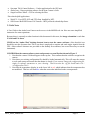
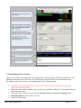
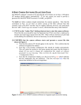
CONFIRM that the camera software starts and presents a screen like that shown in Figure 2.
1. Note that the camera S/N should appear in the top bar. This confirms that the software recognizes the
camera.
2. Note that a pre-existing configuration file should be loaded automatically. This will cause the camera
to cool upon startup and ensure that the shutter is closed. (If you want to change the configuration file,
simply set software parameters to your choosing. Then overwrite the .cfg file listed under File >Configuration Files.)
3. Note that the temperature display in at the lower left is red, which indicates that the temperature has
not stabilized. That box will turn blue when the camera has stabilized at the set temperature.
IRTF_Moris_Manual.doc
Page 6
Solis v.4.6.5 (POETS camera software) as it appears upon successful startup.
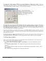
To take data, the shutter must be open. CLICK Hardware->Shutter Control, and ensure that the
Internal Shutter is set to permanently open. For longer exposures, a manual shutter setting could be used;
however, this mode is not tested.
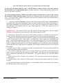
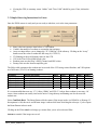
To set data-taking parameters, CLICK on the white wrench icon (denoted by an arrow in Fig. 3) or use
the Acquisition->Setup Acquisition menu. Typically, the configuration file starts with the settings shown in
Fig. 3. The exposure time, number of exposures, and readout rate amplifier will be the selections that are
usually altered between frames.
a. “Triggering” should be Internal if you plan to take frames using the Solis software; External Start if
you plan to take a data cube containing the number of frames listed in the Solis software and starting at a
GPS trigger; External if you want the camera to take a data cube containing the number of frames
specified in the Solis software with each frame being triggered by a GPS repeat signal. See (9) for
sending GPS triggers.
Important note: The camera software and GPS software do not communicate with one another.
Therefore, you must hand-record the start time of any images triggered via GPS.
b. Note that the “Shift speed” is the time to shift electrons per CCD row. Number selections listed in
brackets will allow the data to read out even more quickly, but are likely to incur some electron loss.
c. “Readout rate” allows selection of the amplifier: 1 MHz (Conventional & Electron Multiplying; EM),
3 MHz (Conventional & EM), 5 MHz (EM) or 10 MHz (EM). Faster readout rates incur higher read
noise – see the specification sheet for details. Note that the EM modes can be run with EM disabled.
Usage of EM modes while disabled removes worry that the avalanche gain will be compromised;
however, taking data in this mode (or even with EM enabled at very, very low EM values) is inadvisable
because the EM must be high enough to compensate for the higher read noise and excess noise factor in
these modes.
d. Readout gain, in e/ADU, is selected by choosing “Pre-amplifier gain”. See the specification sheet for
values corresponding to the listed numbers.
e. The “Number of prescans” can be set to a non-zero value if you would like to ensure that the first
frame of every saved cube does not contain any residual signal. Note that prescans have not been used
with occultation (or other time-specific) observations. We typically drop the first data frame during
analysis.
f. Ensure that the “Frame Transfer” box is checked. The camera has not been tested in non-frame
transfer modes.
g. Note that frames (.fits or otherwise) can be opened in either the Solis software (under the File menu)
or in ds9
h. Note that the WinScp icon on the desktop is a user-friendly interface for transferring files between
POETS and stefan, or other remote servers.
IRTF_Moris_Manual.doc
Page 7
Preview
Take Data
Stop Taking Data
Data Acquisition Settings
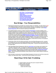
Figure 3. Data acquisition settings for typical operation of the POETS camera.
To preview data, (take and see frames without storing) CLICK on the video camera icon labeled
“preview” in Fig. 3. The stop button labeled in Fug. 3 will stop the preview.
To take data, CLICK on the camera icon labeled “take data” in Fig. 3. The stop button labeled in Fug. 3
will abort.
Important Note: The configuration file is currently set to automatically spool, save, and incrementally
number the data cubes. (See next item.) If you do not want to autospool and save, you must change these
settings. With no spooling, any image you take should display and then allow you the option to save and
name.
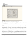
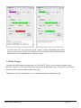
To spool and automatically name data, GO TO the Setup Acquisition window and CLICK on the
“Spooling“ and/or “Auto-Save” tabs. The typical settings for these are shown in Figs.4a & b. Spooling
ensures that every frame is saved – when taking a very large data cube this prevents total data loss should a
mid-cube crash occur. When the “Use Append Setting from Autosave tab” is selected, the spooled data are
compiled into a data cube and named via the pattern selected in “Auto-save”.
IRTF_Moris_Manual.doc
Page 8
Typical settings for data storage: the “Spooling” and “Auto-save” tabs.
IRTF_Moris_Manual.doc
Page 9
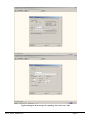
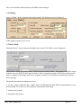
To change the cooling settings, CLICK on the menu Hardware->Temperature Control. Adjust the
temperature by entering a value in ºC or moving the adjustment bar. The cooler should be on and the box for
“on at program startup” should be checked. See Fig. 5 for typical settings.
Figure 5. Typical settings for the
temperature control panel for POETS. The
minimum cooling depends on ambient
temperature: for reference, at 68º F the
camera can cool to –60C.
To trigger the camera using the GPS, SELECT all of the acquisition settings you desire. CLICK on
the camera icon to take data. Next, enter the GPS software and select POP (lower right). Set start time
(UT) and repeat interval, as desired. The camera will sit until it receives the trigger (at the POP time you
set), at which point frames will display in the software.
Important Note: Again, note that the GPS start time is NOT RECORDED anywhere other than when you
type it into the GPS software. The time in the FITS header will be that when the take data command was
given in the Solis software.
To close the software, simply click File->Close. The camera fan may continue to run if the software is
closed but the computer is still running. It is best to shut down the entire system at the end of each night.
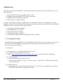
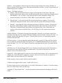
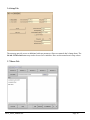
2.2.3 Filter Wheel’s SMGUI
There is a GUI on the POETS computer screen that allows control of the filter wheel. Fig. 6 shows screen
shots of the GUI upon startup and when connected.
(1) Click on the icon “shortcut to smgui” on the desktop. A screen shot of the display is shown
below.
(2) Click the “connect” button. The computer will interface with the filter wheel an initialize to
position 1.
(3) To change to the desired filter, select the filter from the drop-down menu under “Control”. Then
click “move to”.
(4) Close the GUI by clicking the red X in the upper right corner.
IRTF_Moris_Manual.doc
Page 10
The filter wheel GUI. (left) Upon start up, the “connect” button is highlighted and must be
pressed to gain control. (right) Once connected, the desired filter can be selected from the
drop-down menu located under in the “Control” section.
2.2.4 Data Transfer
Currently, the only method to transfer data is to use WinSCP. There is an icon for this program on the
desktop. Connect to occult and transfer data onto the current data transfer disk. This process must be done
from the POETS computer and does take a long time.
SpeX data are typically in the directory /scrs1/guidedog/ and can be obtained via sftp.
IRTF_Moris_Manual.doc
Page 11
3. MORIS LINUX
After moris was delivered to the IRTF, a linux based instrument was developed. Why use Moris Linux (verse
Moris Windows)?
Provide a IRTF like GUI, very similar to Spex’s GUI.
Integrates better with the IRTF TCS, SPeX, and network.
Simplify user options for newer observers.
Moris can act as a guider for SpeX.
Of course, simplifying the option is actually hides or sets so options for the user. For most moris user, this
should be an issue. If it is, the Window XP environment still exist to provide user with FULL access to MORIS
capabilities. Some of the features set by Moris Linux are:
Ixon Advance EM Gain is disabled.
Ixon Readmode is set to “Image”.
Ixon Frame Transfer is enabled.
Ixon BaseLineClamp is Disabled.
Ixon automatic shutter mode not available (only Open or Closed).
3.1 Accessing Moris Linux
The IRTF staff should start MORIS’s IC, XUI, and DV in a Stefan VNC session. You just need to connect to
his VNC session to use MORIS. Contain the TO or Staff for the vnc password of the day. Use your
vncviewer an connect to Stefan;12
1. Prerequisites
For summit users, you will need an IRTF guest account.
For remote users, you will need a vnc viewer.
Refer to http://irtfweb.ifa.hawaii.edu/observing/remote_obs/ for accounts and VNC information.
2. For summit observers:
Login to Stefan using your guest account.
From an xterm, run the vnc viewer: “vncviewer moris”. Contact the TO or IRTF staff for the VNC
password of the day.
3. For remote observers:
Connect to the vnc session “stefan.ifa.hawaii.edu:12” via you VNC viewer application. Contact the
TO or IRTF staff for the VNC password of the day.
IRTF_Moris_Manual.doc
Page 12
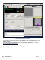
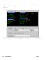
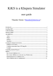
Moris Linux running in the VNC Session
On the left side you should see the Moris XUI (X Users Interface). The XUI provide full control for the
camera’s operations.
On the right is DV, IRTF’s standard data viewer for instrumentation. Documentation for DV is at
http://irtfweb.ifa.hawaii.edu/Facility/DV/
The follow diagram explains the major sections of the XUI:
IRTF_Moris_Manual.doc
Page 13
Moris XUI diagram
3.2 Initializing the iXon Camera.
When you are ready to start observing, Set the ImageSource to IXON. This will load the camera driver and
initialize the hardware. Once this has be successful opened, check the IXON Cooler and Shutter setup.
By clicking on the Device Icons, you can change the Cooler or Shutter setting.
After observing, set the Image Source back to “Off”. This closes the camera driver, putting the
camera into a safe idle mode.
If the Ixon camera fails to initialize, type “go.init” to re-iniitialize. (Often the 1st init attempt fails, and
the second one works).
Click on the Ixon Cooler icon if you need to turn the cooler on and enter the setpoint of -65.
Check the shutter to ensure open or closed.
Check the Filter setting.
IRTF_Moris_Manual.doc
Page 14
If using the GPS, its summary status “Online” and “Time Valid” should be green. If not, inform the
TO.
3.3 Simple Observing Instructions for Linux
Once the IXON camera is ready and you are ready to take date, review the ixon parameters:
Itime is the ixon exposure time before a CCD readout.
Coadd is the number of readouts to accumulate into an image.
Array text input allows you to change the “X Y Wid Hgt” of the subarray. Clicking on the “Array”
button resets the value to readout the full array (0,0 512x512).
XY Binning set the pixel binning value for the CCD.
VSS is the iXon Vertical Shift speed value.
Readout menu sets the iXon’s AMP, Channel, and HSS values.
Preamp Gain sets the Ixon Preamplifier gain.
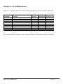
The follow table summaries the readout rate in seconds of the CCD using various Readout, and VSS options
on a full frame (512x512, no binning) readout.
Read Menu
CV_14bits_03Mhz
CV_16bits_01Mhz
EM_14bits_10Mhz
EM_14bits_05Mhz
EM_14bits_03Mhz
EM_16bits_01Mhz
Readout Description
Conv Amp, 14bit sample, 03Mhz HSS
Conv Amp, 16 bit sample, 01Mhz HSS
EM Amp, 14 bit sample, 10Mhz HSS
EM Amp, 14 bit sample, 05Mhz HSS
EM Amp, 14 bit sample 03Mhz HSS
EM Amp, 14 bit sample 01Mhz HSS
VSS3.3
VSS1.7
VSS0.9
VSS0.5
VSS0.3
0.11011 0.10028 0.10000 0.09965 0.09955
0.28557 0.28473 0.28432 0.28411 0.28401
0.03027 0.02944 0.02902 0.02881 0.02871
0.05876 0.05783 0.05751 0.05730 0.05720
0.10150 0.10067 0.10025 0.10004 0.09994
0.28668 0.23584 0.28542 0.28521 0.28511
It is recommended that users use “CV_16bits_01Mhz” and VSS=3.3 unless faster readout is necessary. Of
course, faster readout rate usually increase the noise. Using subarray and binning can also decrease the
readout rate.
Select CamMode Basic. The Beam.Pattern tells the camera if the image in take is a BEAM A or B image. If
beam.pattern is AB, then an A and B beam image is taken while beam switching the telescope. Cycles repeats
the Beam.Pattern in basic mode.
Clicking on the Filter wheel icon brings up a menu allow you to select a desired filter.
Autosave controls if the images are saved.
IRTF_Moris_Manual.doc
Page 15
Once you selected the desired options, click GO to take and image.
3.4 Guiding
Select “Guiding” on the Cammode tab enables guiding. The following screen is displayed:
While guiding, images can be saved.
3.5 Movie Mode
Selecting “Movie” on the cammode tab enables movie mode. The follow screen is displayed:
Movie mode is a high speed image mode ( The Ixon calls its Kinetic mode ). The software will buffer images
in RAM, and write 3D FITS data when the RAM is filled. Continually writing 3D FITS files until the movie
mode is completed. The images in the movie sequence are taken at a fixed period, with minimal overhead
between images.
The general procedures for taking a movie are:
1. Use basic mode to adjust the itime, coadds, Array, XY Binnning and other IXON readout parameter to you
desired setting. Go on, once you have produced a satisfactory basic image.
2. Switch to movie mode.
3. Setup Movie parameters:
IRTF_Moris_Manual.doc
Page 16
NFrames – are the number of frames in the movie. Movie mode will stop after saving “NFrames” of
data, or when the STOP button is press. Enter the desired number of frames, or enter a large number and
manual stop the movie sequence.
Trigger – The trigger option are:
Internal – The ixon will start the movie sequence and acquisition of each frame. This is the
simplest option, but the timing of the start and subsequences frame are performed internally by the
IXon hardware. The “act_ktime” values shows the period of the subsequence images. The
absolute timestamp of your data (or TIME_OBS ) is good to better that 0.1 seconds.
External_Start – A start pulse by the GPS unit will start the movie sequence. The ixon will
schedule the subsequence frames. The act_ktime show the period of the subsequence images.
External – A repeating GPS pulse will trigger each frame of the movie sequence. This provides
the most accurate timing of each the image. Frame transfers and readouts are slaved off of the
GPS pulses. In External mode, itime becomes an ‘Exposure Delay’ term. In this mode, the
software will set itime to 0.000 (No Delay). The GPS Rep_ms is the exposure time between
readouts.
AutoSet.GPS.Start – If External or External_Start triggering is selected, you will need to specify the
start time of the GPS unit. The AutoSet.GPS.Start, if enable, will auto load the “current UTC Time + 19
seconds” into the GPS when the GO is press. If AutoSet.GPS is not set, you must manual enter the
GPS.Start Date and Time.
GPS.Start text box – If you are manually entering the start time, type the UTC Date and Time into the
text area under the AutoSet.GPS.Start. The format is YYYY-MM-DD HH:MM:SS.SSS. Hit return to
accept this input. The “UTC+30s” button will load the current data and time (plus 30 seconds) into the
text area.
GPS Pulse (sec): For External Trigger ONLY, you will need to enter the period of the GPS pulse here.
This needs to be larger that the act_ktime (in millseconds). If you enter a value that is too low, the
software will set it in a minimal value.
Update2DV – Moris updates the DV image at a rate set by this menu (Images can be cache and saved at
a higher rate). Set the desired DV update rate. Note for VNC user a lower rate may be optimal as a
higher display rate may saturate the VNC bandwidth.
Enable Autosave. In move mode, autosave must be enabled.
Coadds are not support in Movie mode. Coadds will be set to 1.
It’s best to setup your movie mode inputs, do a test with a limit number of “nframes”. Check the timing.
Now you will be ready to start you observing.
“Appendix E – Movie Mode Time” – provide information on determining the timestamps of the movie
frames.
IRTF_Moris_Manual.doc
Page 17
3.6 Setup Tab
The setup tap provide access to additional software parameter. Observers normal don’t change them. The
Go.init or Filter.init button may need to be used to re-initialize. Here are the normal moris setup values.
3.7 Macro Tab
IRTF_Moris_Manual.doc
Page 18
The macro tab allow observer to execute moris IC command located in a text file. Complex or repetitive
sequences can be easily done using macros.
3.8 GPS Tab
The GPS tab display detail status from the GPS, and provide some widget to command the GPS unit. User
should refer to the TM/4 manual, as the spex GUI duplicate the data and term used in the vendor’s TM/4 GPS
manual and software.
IRTF_Moris_Manual.doc
Page 19
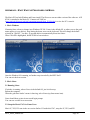
APPENDIX A – STAFF START UP PROCEDURES FOR MORIS
The Moris PC has both Window and Linux install. The Observer can run either version of the software. A IP
KVM is attached to the Moris PC. Connect to KVMCass
(http://irtfweb.ifa.hawaii.edu/irtf/computing/network/kvm_201406.php) to view the PC’s console.
1. Moris Windows
If running linux, reboot to change in to Windows XP OS. Linux is the default OS, so when you see the grub
menu appear (or even before), keep hitting the down arrow on the keyboard, This will change the default
selection to “WinXP”. You have 10 seconds before it automatically boots into Linux:
When “WinXP is highlighted, hit RETURN to boot windows.
Once the Window OS is running, no further setup is needed by the IRTF Staff.
You can exit the kvm session.
2. Moris Linux
2.1 Running Linux
If window is running, reboot. Linux is the default OS, just let it boot up.
Reboot the computer
When the grub boot loader’s menu is showing, select Linux (top linux menu item).
Linux should boot up into its text mode login prompt.
You can now exit the kvm vncsession.
2.2 Setup the Moris VNC for Linux Users
Moris IC, XUI, DV runs in the vnc session Stefan:12. Inside this VNC, setup the IC, XUI, and DV.
IRTF_Moris_Manual.doc
Page 20
IC:
Select “xterm to Moris PC” on the openwin menu.
Login
cd current/ic
morisic
XUI:
Select “xterm to Moris PC” on the openwin menu.
Login
cd current/xui
morisxui
IC:
Select “xterm to Moris PC” on the openwin menu.
Login
cd current/dv
dv
After the IC, XUI, and DV is running initialize the IXON camera and take an image:
1. First do a filter.init to initialize the filter wheel (button is in the setup tab).
2. Then selection the IXON camera. This tries to load the device driver for the camera. It usually fails on
the first they. Repeat a few time either by selecting the “Off” Tab, then the “IXON” table again. Or my
typing “go.init” in the command line.
3. If the camera fails to initialize after 5 attempts, then connect to spexPwr. Power down the
“moris_camera” for 30 seconds. Power up. Then repeated these steps.
If the camera still fails, I have tried rebooting into Windows, then tried to take an image using the Andor Solis
program. (This is the window application supplied by the vendor). If Solis take an image, reboot back on linux,
and try again.
IRTF_Moris_Manual.doc
Page 21
APPENDIX B - MOUNTING CHECKLIST
See the schematic in Figure 1 for the IRTF POETS setup.
Important note: power should be off when attaching and detaching cables. The best way to setup is to have all
power off, connect everything, then turn all power on.
Items to check in order to confirm proper hardware setup for POETS usage:
Foreoptics box mounted on side of SpeX
Camera mounted on bottom of fore-optics box
Manual shutter between POETS and SpeX is open
BNC cable attached to GPS antenna at top of telescope
BNC cable attached to “antenna” port on back of GPS
Serial octopus cable plugged into the back of the GPS
36-pin white cable attached to camera and back of computer
Camera power cable plugged into jack on camera and an outlet
SMB plugged into the “external trigger” connection on camera and the “output” BNC on the GPS octopus
cable
Warm room cable connected to back of computer
Computer power cable plugged into computer and an outlet
GPS power cable plugged into jack on the GPS octopus cable and an outlet
Power on for the following:
(i)
GPS [lights on front will glow];
(ii)
camera [can’t confirm power on until software is started];
(iii) computer [lights on front will glow].
Confirm that computer power and connection are functional by bringing up display in the warm room
Can confirm that GPS is connected by clicking on “Spectrum” icon on the Windows desktop: if no
connection is made, an error message will appear
Can confirm that camera is working by clicking on the “Andor iXon” icon on Windows desktop: if no
connection is made, an error message will appear
Can confirm that camera power is working by watching the red cooling notice at the bottom left of the
camera software display – it should read below “0º C” within a minute or two of the software startup
IRTF_Moris_Manual.doc
Page 22
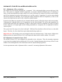
APPENDIX C – FILTER WHEEL DETAILS
Moris has a 10 position filter wheel. The following table summaries the filters installed in this wheel.
Menu Name
Description
Open
SDSS_g
SDSS_r
SDSS_i
SDSS_z
Johnson_V
VR
LPR_600
LPR_700
890_19nm_CH4
Wavelen
(microns)
0.7
0.48
0.62
0.76
0.86
0.55
0.6
0.73
0.77
0.89
Step Position Encoder IO value
0
0
18493
1
16445
2
14392
3
12338
4
10282
5
8226
6
6170
7
4114
8
2058
9
Note: Wavelen column contains the values used by the software for differential refraction caculations.
IRTF_Moris_Manual.doc
Page 23
APPENDIX D - FORE-OPTICS AND MOUNTING BOX NOTES
D.1 - Adjustment of the z-extension
The camera can be focused by adjusting the “z-extension”. This is the threaded plate system at the base of the
box. This system is comprised of three components: (i) an inner- threaded aluminum piece (32 threads per
inch), (ii) and outer-threaded steel plate which screws into (i) allowing for a range of xx inches vertical motion,
and (iii) an aluminum base plate which attaches to (i) and the camera. Component (ii) sets the camera height
and can be adjusted via threading. By loosening the sliding attachments between components (i) and (iii), the
camera is decoupled and can move in the z-direction without rotation.
In practice, the sliders on component (iii) are loosened and the camera is allowed to drop to the lowest position.
Component (ii) is threaded into or out of component (i) to the desired height. The camera and component (iii)
are then lifted until flush with component (ii) (there is fitted groove between components (ii) and (iii) in order
for the connection to be light tight), and the sliding attachments on component (iii) are tightened to hold the
camera in place.
The system should be setup to be cofocal with SpeX. Different filters should not effect the focus to a detectable
degree. Therefore, the focus should not require adjustment during regular use.
Important note: The focusing system was designed to allow for maximum range. If the camera is lifted to the
highest position, the mount for lenses 2 & 3 could impact the shutter and/or camera window. Be careful!
D.2 Adjustment of mount for lenses 2 & 3
The mount for lenses 2 & 3 was designed to be adjustable in the z direction. Thus, the mounting component
screws into the mounting bracket with threads of 14 per inch. Optimal alignment places the top of lens 2 in the
middle of the mounting bracket. This should not need to be adjusted during regular use.
See the important note under “adjustment of the z extension” concerning adjustment of this mount.
IRTF_Moris_Manual.doc
Page 24
APPENDIX E – MOVIE MODE TIMING
This section provides information on determine the time stamp of your movie mode images. The following
example use 1.0 sec itime, 1 coadd.
1. Internal Trigger
In Internal Trigger, the Ixon camera start its data acquition when commanded by the PC.
The PC reads the computer’s system time after command the IXON to start. This time should be accurate to
better than 0.1 seconds. The linux computer clock is synced to the GPS using NTP.
Key FIT headers are:
TIME_OBS=
DATE_OBS=
ITIME
=
A_ITIME =
A_KTIME =
'19:57:33.470932'
'2011-08-23'
1.0000
1.000000
1.001740
/
/
/
/
/
UT TIME OF ACQISTION ('hh:mm:ss.ss')
UT DATE OF ACQUISITION ('yyyy/mm/dd')
INTEGRATION TIME IN SECONDS
IXON actual exp sec
IXON actual kinetic sec
The TIME_OBS provide the time for the 1st image. The repeat period is given by A_KTIME.
So,
Movie image 0 = DATE_OBS
= 19:57:33.470932
Movie image 1 = DATE_OBS + A_KTIME.
= 19:57:33.470932 + 1.001740 seconds
Movie image 2 = DATE_OBS + 2*A_KTIME
= 19:57:33.470932 + (2*1.001740) seconds
…
Movie image N = DATE_OBS + N*A_KTIME.
The exposure time of a single coadd is provided by ITIME. This should match the A_ITIME.
2. External Start
In External Start, a GPS pulse will start the movie acquisition. The subsequence frames are scheduled by the
Ixon camera, and the A_KTIME is the period between frames.
Key FIT headers are:
TIME_OBS=
'19:58:52.000000' / UT TIME OF ACQISTION ('hh:mm:ss.ss')
DATE_OBS=
'2011-08-23' / UT DATE OF ACQUISITION ('yyyy/mm/dd')
MV_TRIG =
1 / MovieTrigger is External_Start
GPS_CMD = '#21,1,+,08232011,195852.0000000,00001000'#21'
ITIME
=
1.0000 / INTEGRATION TIME IN SECONDS
A_ITIME =
1.000000 / IXON actual exp sec
A_KTIME =
1.001740 / IXON actual kinetic sec
MV_TRIG show External Start.
GPS_CMD, show the POP command given to the GPS in order to start the movie. The GPS manual is available
on the IRTF MORIS web site. The DATE and TIME_OBS should match the start pulse command by the GPS,
in this case 19:58:52.0 is the start time.
The TIME_OBS provide the time for the 1st image. The repeat period is given by A_KTIME.
IRTF_Moris_Manual.doc
Page 25
So,
Movie image 0 = DATE_OBS
Movie image 1 = DATE_OBS + A_KTIME.
Movie image 2 = DATE_OBS + 2*A_KTIME
…
Movie image N = DATE_OBS + N*A_KTIME.
= 19:58:52.0
= 19:58:52.0 + 1.001740 seconds
= 19:58:52.0 + (2*1.001740) seconds
The exposure time of a single coadd is provided by ITIME. This should match the A_ITIME.
3. External
In External, a GPS pulses will cause the image on the CCD to be transferred to the readout area on the rising
pulse of the GPS POP signal. The image in the readout area, are then sampled and saved.
Key FIT headers are:
TIME_OBS=
'23:32:50.000000' / UT TIME OF ACQISTION ('hh:mm:ss.ss')
DATE_OBS=
'2011-08-24' / UT DATE OF ACQUISITION ('yyyy/mm/dd')
MV_TRIG =
2 / MovieTrigger is External
GPS_REP_=
1000 / GPS Pulse Repeat Period, milliseconds
GPS_CMD = '#21,2,+,08242011,233250.0000000,00001000,6 '
ITIME
=
0.0000 / INTEGRATION TIME IN SECONDS
A_ITIME =
0.000010 / IXON actual exp sec
A_ATIME =
0.287280 / IXON actual Accum sec
A_KTIME =
0.287280 / IXON actual kinetic sec
The GPS_CMD, show the POP command given to the GPS in order to start the movie. The GPS manual is
available on the IRTF MORIS web site. The DATE and TIME_OBS should match the start pulse command by
the GPS. Note the TIME_OBS match up with the GPS_CMD start pulse (23:32:50.0), and the GPS_REP is
1000 ms (same value used in the GPS_CMD).
The 1st image should be discarded. The Time Stamp values are valid for the remaining images.
The TIME_OBS provide the time for the 1st image. The repeat period is given by A_KTIME.
So,
Movie image 0 = DATE_OBS
= Undefined.
Movie image 1 = DATE_OBS
= 23:32:50
Movie image 1 = DATE_OBS + 1*GPS_REP
= 23:32:50 + (1*1.000) seconds.
Movie image 2 = DATE_OBS + 2*GPS_REP
= 23:32:50 + (2*1.000) seconds.
…
Movie image N = DATE_OBS + N*GPS_REP.
The exposure time is equal to the GPS_REP, in this example it is 1.000 seconds.
IRTF_Moris_Manual.doc
Page 26
APPENDIX F – ADDITIONAL NOTES
The camera for this system is an Andor Technology iXon. It is an off-the-shelf camera, with a backilluminated, frame-transfer CCD (512 x 512, with 16 m square pixels).
Model
Serial Number
Camera:
DU-897E-CS0-#BV
X-3020
CCD:
E2V TECH CCD97
05445-04-23
PCI Card:
CCI -22
C-1188-B
E.2 -Cooling
The camera housing contains a thermoelectric cooler. This cooler is powered via a 2.1 mm Jack connector
which goes through an adapter (Input: 100-250 V, 47-63 Hz, 0.4 A, Output: 7.5 V, 4.0 A) and to a standard 120
V U.S. plug.
The minimum cooling depends on ambient temperature. For reference, at 68ºF the camera has a minimum
cooling of -60ºC. An alarm will sound if the camera overheats, which can happen if the air vents are blocked.
Additional cooling can be achieved through water cooling; however, this method has not been tested for the
IRTF POETS system.
E.3 PCI interface
The controller card for the camera is a ¾-size PCI card. The camera-computer cable is 6-m long and has
proprietary 36-way connectors. PCI card and cable are provided by Andor Technology.
E.4 Trigger cable
The external trigger cable is 50 with an SMB on the camera end and a BNC on the user end. The input is
TTL level and CMOS compatible and has 470 impedance. The camera comes with a standard, approximately
6-ft long cable. This system uses a custom 20-ft cable (RG174) from Stonewall Cable, Inc.
E.5 GPS
The GPS for this system is a Spectrum Instruments, Inc. Intelligent Reference TM-4. A complete user manual
is located online at http://occult.mit.edu/_graphics/POETS/ info/TM4manual.pdf and hard copies are at the
IRTF and MIT.
The GPS is connected to the computer, trigger cable, and power via an octopus serial cable. A serial connection
goes to the computer, a BNC connection from the “output” octopus cable goes to the “external trigger” SMB on
the camera, and power comes from an adapter (Input: 120-140 V, 0.4 A, Output: 24 V, 0.4 A) with a standard
120 V U.S. plug. A BNC cable runs from the “antenna” GPS port to the GPS antenna mounted at the top of the
telescope.
IRTF_Moris_Manual.doc
Page 27
APPENDIX G – PROBLEMS AND SOLUTIONS
Some Troublelog problems and solutions are described here as a resource for future problems.
1. Red Filter Wheel Message “IOBits!=Filter”.
Each filter position in moris has unique bit value.
After moving the filter wheel, moris checks to see if the IO Bit value matches the filter position. If it
does not match, you will see this message. It is likely the filter is not in the correct position. The user
should initialize the will and perform the move again.
2.
“sock communication error” while performing a filter init or move.
Moris communicates to the filter wheel via a telnet connect to a digiport. This indicates an error with the telnet
connection. Try the following to clean the problem:
First “ping morisdigi”. If the ping fails, the digi is offline. Check power and cabling to the digi.
a. Kill any lingering telnet connection to the digi:
a. From Stefan, telnet to moris digi: “telnet morisdigi”
b. Login as “root”, passwd is “ dbps”.
c. Type “kill 1” to kill any connections on port 1.
d. “quit” to exit moris digi.
e. Initialize the filter wheel on moris.
If the “kill 1” does not work, substitute “boot action=reset”. This warm boots the digi.
IRTF_Moris_Manual.doc
Page 28