1
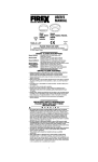
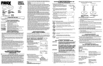
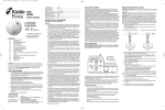
58°C TEMPERATURE RATING
MODEL H230CT
HEAT ALARM WITH 9V BATTERY BACK UP
PLEASE READ AND SAVE THIS MANUAL
Installer: Please leave this manual with
the occupier (or, in the case of a house
in multiple operation, with the owner).
CONTENTS
Heat Alarm Features
Specifications
Important Safety Information
Heat Alarm Location
Heat Alarm Siting
How to Install This Heat Alarm
Interconnecting Heat Alarms
Red and Green LED Indicators
Testing the Heat Alarm
Maintenance and Cleaning, Battery Replacement, Repair
Fire Safety Rules and Preventing Hazardous Situations
Fire Procedure
What to Do in Case of Fire
Troubleshooting
Guarantee
!WARNING: HEAT ALARMS ALONE ARE NOT SUFFICIENT FOR LIFE SAFETY AS THEY ARE NOT DESIGNED TO
DETECT SMOKE. THEY ARE INTENDED TO DETECT TEMPERATURES OF 58°C AND ABOVE TO PROVIDE AN
ADDITIONAL SOURCE OF INFORMATION THAT IS SUPPLEMENTARY TO THAT PROVIDED BY SMOKE ALARMS TO
INCREASE THE PROBABILITY THAT AN EARLY WARNING WILL BE PROVIDED AND SO ENHANCE LIFE SAFETY AND
PROPERTY PROTECTION. SEE HEAT ALARMS HAVE LIMITATIONS IN THE IMPORTANT SAFETY
INFORMATION SECTION OF THIS MANUAL.
HEAT ALARM FEATURES
• This heat alarm is powered from a 230V AC supply, and has a DC battery
back-up source. AC/DC heat alarms offer added protection in the event of a
power failure.
• Unique power connector prevents interconnecting with incompatible heat
alarms, smoke alarms, or security systems.
• Model H230CT heat alarms can be interconnected with as many as 35 other
Firex heat alarms or Firex 230V AC smoke alarms. Interconnectable Firex smoke
alarms include: GC240, I240C, IAR230C, PG240, PAD240, PADC240 and PAR230.
Interconnectable Firex heat alarms include: H230, H230CT, and HR230CT.
• Optional use tamper-resistant feature serves as a safeguard against tampering.
• Model H230CT has a unique “battery missing” device. The heat alarm will not
attach to the mounting bracket if a battery is not in the battery compartment.
• The heat alarm will sound a short beep about once a minute if the battery is low.
• Multi-purpose green and red LEDs indicate that the heat alarm is connected to the
AC supply, is working normally, or is in alarm.
• Loud alarm sounder – 85 decibels [dB(A)] at 3m – will sound to alert you to
an emergency.
• Test button checks heat alarm operation.
SPECIFICATIONS
MODEL NUMBER
ELECTRICAL RATING
INTERCONNECTING FIREX
SMOKE AND HEAT ALARMS
(OR PATTRESS WITH RELAY)
H230CT
230V AC, 9 VOLT DC BATTERY BACKUP
UP TO ANY COMBINATION OF 35 OTHER FIREX HEAT
ALARMS (MODEL H230CT, H230, HR230CT) OR FIREX
SMOKE ALARMS (MODELS GC240, I240C, IAR230C,
PG240, PAD240, PADC240 AND PAR230)
NOTE: THE ABOVE FIREX MODELS ALSO MAY BE INTERCONNECTED
WITH FIREX PATTRESS WITH RELAY (MODEL PATR).
1
70°C
IMPORTANT SAFETY INFORMATION
111-279
p.1
p.1-2
p.2
p.3
p.3
p.4
p.5
p.5
p.5
p.5-6
p.6-7
p.7
p.7
p.8
p.8
TO
PLEASE READ AND SAVE THESE INSTRUCTIONS
!WARNING
• This heat alarm requires constant 230V AC power AND a healthy 9V DC
battery to operate properly. This heat alarm WILL NOT work if AC power is
not connected, or has failed or been interrupted for any reason, AND the batteries have been removed or are flat or improperly connected. DO NOT use
any other kind of battery except as specified in this manual. DO NOT interconnect this heat alarm to any other type of smoke alarm or heat alarm or auxiliary device, except those listed in this manual.
• The TEST button accurately tests all heat alarm functions. DO NOT use any other
test method for routine testing. Test heat alarm weekly to ensure proper operation.
• Higher ceilings will increase the time needed by the heat alarm to detect a
fire. In most dwellings the ceiling height will keep this reaction time within
acceptable limits. However, ceilings with a height of over 6m may delay the
reaction time of the heat alarm significantly. Advice from your local distributor
or Fire Brigade should be obtained when installing a heat alarm on a ceiling
higher than 6m.
• This heat alarm should be installed only by a qualified electrician. The
installation should comply with BS 7671 and all prevailing local, regional and
national codes.
• This heat alarm is designed to be used only as part of the protection of a
single family dwelling or a house in multiple occupation (HMO) of no more
than two stories. It also may be used in conjunction with smoke alarms within
individual flats or apartments in larger houses in multiple occupation, to
provide an early warning to occupants of a fire in a room within the dwelling,
but a communal fire alarm system also should be provided in such cases. DO
NOT install this heat alarm in any other buildings, such as hotels, motels,
dormitories, hospitals, nursing homes or group homes of any kind. In these
occupancies, a complete automatic fire detection and alarm system,
complying with BS 5839: Part 1, should be installed.
• Heat alarms should be used only in conjunction with smoke alarms, with
which the heat alarms should be interconnected, in order to provide early
warning of heat, smoke, or fire. Smoke alarms should be installed on every
level of the dwelling.
• Interconnected heat alarms and smoke alarms offer maximum protection.
By interconnecting heat alarms and smoke alarms, when one unit senses
heat, smoke, or fire, and sounds its alarm, all others will sound as well. DO
NOT connect this heat alarm to any other type of alarm except those stated in
this manual or an approved auxiliary device.
• Heat alarms interconnected with smoke alarms may not alert every household member every time. The alarm sounder of the heat alarm is loud in order
to alert individuals of a potential danger. However, there may be limiting
circumstances where an occupant may not hear the alarm (e.g., outdoor or
indoor noise, sound sleepers, drug or alcohol usage, impaired hearing, etc.).
Household members must hear the alarm’s warning sound and quickly
respond to it to reduce the risk of damage, injury, or death that may result
from fire.
• Check carefully that, when any one device operates, the alarm signal given
by interconnected devices is clearly audible throughout the building,
particularly in bedrooms, where it is essential that the alarm signal will wake
sleeping occupants.
• This heat alarm can sound an alarm only when it detects temperatures of
58°C or above. Heat alarms do not sense smoke or gas. In some fires,
hazardous levels of toxic chemicals and smoke can build up before a heat
alarm will operate. Temperatures may not reach 58°C to activate the heat
alarm QUICKLY ENOUGH to ensure safe escape.
• Some fires are slow smouldering, low heat-producing, or are in a different room
to that in which the heat alarm is located, or the heat from the fire may bypass
the alarm – the heat alarm may not give a warning under these circumstances.
• HEAT ALARMS HAVE LIMITATIONS. This heat alarm is not guaranteed to protect lives or property. Heat alarms are not a substitute for insurance.
Householders should insure their lives and property. In addition, as with any
electronic device, it is possible for the heat alarm to fail at any time.
• Never paint this heat alarm.
2
HOW TO INSTALL THIS HEAT ALARM
Heat alarms give an audible warning when the temperature at the alarm reaches
58°C. Heat alarms are ideal for kitchens, garages, cellars, boiler rooms, attics and
other areas where there are normally high levels of fumes, smoke or dust which
preclude the use of smoke alarms due to the risk of false alarms.
Guidance on fire detection in dwellings is contained in BS 5839: Part 6. For normalsized bungalows, two-story houses, flats and maisonettes, the British Standard
recommends that the minimum level of protection should comprise smoke alarms in
the hallways and staircases. This minimum standard necessitates one smoke alarm
in the hallway of a typical bungalow or one smoke alarm on each level of a two-story
house. Heat alarms should not be used in these circulation areas. If there are, for
example, long hallways, even the minimum standard may necessitate additional
interconnected smoke alarms.
If, however, the design of the dwelling does not comply with modern fire safety
standards, or if factors such as the presence of several young children, elderly
occupants or disabled people, or smokers, the use of portable heaters or solid fuel
fires during the night, or the use of electric blankets, particularly by the elderly, the
British Standard advises that additional detection devices, installed within rooms,
may be necessary.
The British Standard recommends that, if the risk justifies the provision of detectors
in a kitchen, boiler room, or other area (except a circulation area) in which smoke
alarms would be likely to give false alarms, heat alarms should be used. However,
the Standard also advises that heat alarms may be installed in other rooms instead of
smoke alarms, provided that the construction enclosing the room (including the door)
can resist fire for a sufficient time after operation of a heat alarm to enable
occupants to escape safely. However, a heat alarm is unlikely to operate early enough
to save the life of anyone asleep in the room in which it is installed. Moreover, a heat
alarm in the room of fire origin may not give sufficient warning for occupants to
escape safely if the door to that room is open.
! DANGER: ELECTRIC
HEAT ALARM
SMOKE ALARM
UNFINISHED ATTIC
SMOKE ALARM WITH
FALSE ALARM CONTROL
BEDROOM
BEDROOM
LIVING ROOM
KITCHEN
UTILITY/
LAUNDRY
GARAGE
BOILER ROOM
HEAT ALARM SITING
FOR BEST PROTECTION, IT IS RECOMMENDED THAT YOU INSTALL A SMOKE OR
HEAT ALARM IN EVERY ROOM. In addition, it is recommended that all smoke and
heat alarms should be interconnected.
Install heat alarm on a standard electrical box or surface mount pattress (Firex Model
PAT or PATR) as close to the centre of the ceiling as possible. If the centre is not
practical, mount the heat alarm no closer than 300mm away from a wall or corner.
In rooms with open joists or beams, all ceiling-mounted alarms should be located
on the bottom of such joists or beams and not up in joist channels. On sloped,
peaked or gabled ceilings, install heat alarm 90cm from highest point. If only wall
placement is possible, install no further than 150mm from ceiling.
DO NOT install heat alarms:
• Directly over the cooker, stove or oven.
• In areas with high humidity, like bathrooms or shower rooms, or areas near
dishwashers or washing machines. Install heat alarms at least 3m away from
these areas if possible.
• Adjacent to, or directly above, heaters, air-conditioning vents or ceiling fans.
• In an area where the temperature may fall below -30°C or rise above 37°C.
• Near fluorescent lights. Electrical noise and flickering may affect the
operation of the heat alarm.
• Closer than 300mm to light fittings.
• In such a position that it is difficult or dangerous to reach for testing,
maintenance or battery replacement.
• Do not site the alarm in an area where water or other liquids may enter the alarm.
3
SHOCK HAZARD.
TURN
OFF POWER TO THE HEAT ALARM CIRCUIT AT THE MAIN
DISTRIBUTION BOARD BY REMOVING THE FUSE OR SWITCHING THE CIRCUIT BREAKER TO THE
OFF
POSI-
TION AND SECURING IT.
!WARNING: THIS HEAT ALARM SHOULD BE INSTALLED ONLY BY A QUALIFIED ELECTRICIAN IN ACCORREGULATIONS FOR ELECTRICAL INSTALLATIONS PUBLISHED BY THE INSTITUTION OF
ELECTRICAL ENGINEERS (BS 7671) AND/OR ALL PRESIDING LOCAL, REGIONAL AND NATIONAL CODES.
DANCE WITH THE
!WARNING: HEAT
ALARMS SHOULD BE CONNECTED ON A SINGLE INDEPENDENT, DEDICATED CIRCUIT
AT THE MAIN DISTRIBUTION BOARD.
NO
OTHER ELECTRICAL EQUIPMENT, EXCEPT COMPATIBLE SMOKE
ALARMS, SHOULD BE CONNECTED TO THIS CIRCUIT. IF YOUR HOME HAS RESIDUAL CURRENT DEVICE
PROTECTION ON THE ELECTRICAL INSTALLATION OR ON INDIVIDUAL CIRCUITS, CHECK WITH A QUALIFIED
ELECTRICIAN TO MAKE SURE THAT FAULTS ON CIRCUITS SERVING SOCKET OUTLETS OR PORTABLE APPLIANCES CANNOT CAUSE INTERRUPTION TO THE SUPPLY TO THE HEAT ALARMS.
HEAT
ALARMS ALSO MAY BE CONNECTED TO A SEPARATE ELECTRICALLY PROTECTED, REGULARLY USED
LOCAL LIGHTING CIRCUIT.
HOWEVER,
THIS WILL MEAN THAT, UNLESS A SEPARATE MEANS OF ISOLATION
IS PROVIDED FOR THE HEAT ALARMS, IT WILL BE NECESSARY TO ISOLATE THE LIGHTING CIRCUIT EVERY
TIME THAT THERE IS A NEED TO ISOLATE THE SUPPLY TO THE HEAT ALARMS; THIS MAY CAUSE INCONVENIENCE OR HAZARDS.
1. Route the household AC supply/interconnect cable into the electrical
accessory box or surface Pattress (Firex Model PAT or PATR).
2. Using a suitably-rated connector (supplied with Firex Pattress models),
connect the neutral supply to the blue lead of the connector plug.
3. Using a suitably-rated connector (supplied with Firex Pattress models),
connect the line supply to the brown lead of the connector plug.
STANDARD ELECTRICAL JUNCTION BOX OR
MODEL PAT OR PATR PATTRESS
CEILING
NEUTRAL
Heat Alarm
-30°C
2
50 M
5.3M
7.7M
6M
HEAT ALARM LOCATION
BLUE
®
58°C
37.8°C
LINE
INTERLINK
230V AC
with 9V Battery
Back-up
TEMPERATURE RATING
MAXIMUM AMBIENT
TEMPERATURE RATING
OPERATING TEMPERATURE
RECOMMENDED COVERAGE
RECOMMENDED SPACING
MAXIMUM DISTANCE FROM WALL
MAXIMUM CEILING HEIGHT
BROWN
ORANGE
©2003 Maple Chase Company
FIREX MODEL H230CT
4. If interconnecting is desired, connect the orange of the connector plug to the
designated interconnect conductor of the household cable. See note
INTERCONNECTING HEAT ALARMS.
5. Insert the completed connector block onto the mounting pins of the Firex
Pattress or recess into the electrical accessory box.
6. Pass the connector plug through the mounting plate of the heat alarm, align
slots and fasten mounting plate securely to the Firex Pattress or electrical
accessory box.
NOTE: If this is to be a single-station heat alarm, cover the orange wire with
electrical tape and tuck it into the electrical box or pattress.
7. Open the battery compartment door.
8. Connect a new, healthy 9V DC battery to the battery connector inside the
battery compartment. Be sure the battery is securely connected. The heat
alarm may beep briefly when the battery is installed.
9. Close the battery compartment door, snapping it into place.
10. Attach the connector plug to the pins on the back of the heat alarm. The plug
will only fit one way, and will snap into place.
11. Gently tug the connector to be sure it is attached securely.
12. Position the heat alarm on the mounting plate and turn it clockwise to lock it
into place.
13. Test the heat alarm to verify the DC battery back-up. See
TESTING THE HEAT ALARM.
NOTE: The heat alarm will not mount to the plate if the battery is not in place.
14. Turn on the power to the heat alarm circuit at the main distribution board.
15. Test the heat alarm for AC operation. See TESTING THE HEAT ALARM.
4
INTERCONNECTING HEAT ALARMS
BATTERY REPLACEMENT
Use 1.5mm2 minimum solid or stranded cable with a rating of 230V. When interconnecting heat alarms and/or smoke alarms, the maximum cable length between any
two should be 450m for 1.5mm2 cable (20 ohm loop resistance.)
This heat alarm may be interconnected with as many as 35 other Firex Model H230,
H230CT, or HR230CT heat alarms or model GC240, I240C, IAR230C, PG240, PAD240,
PADC240 or PAR230 smoke alarms. DO NOT connect to any other type or model of
heat alarm or smoke alarm. If interconnecting to Firex Pattress with Relay (Model
PATR) only 12 total Firex models may be interconnected.
Connect all interconnected heat and smoke alarms to a single final circuit. Wiring
must conform to I.E.E. Regulations for Electrical Installations (BS 7671).
Always turn off the AC power to the heat alarm before replacing the battery. Replace
the battery at least once annually, or immediately when the low battery signal
sounds once a minute, even though the heat alarm is receiving AC power.
Use only the following batteries as replacements in this heat alarm: Eveready 522
or 1222, Duracell MN1604 or Ultralife UL9V-J.
!CAUTION: DANGER
OF EXPLOSION IF BATTERY IS INCORRECTLY REPLACED. USE ONLY THE BATTERIES
SPECIFIED IN THE USER MANUAL.
!WARNING: DO
NOT USE ANY OTHER TYPE OF BATTERY, EXCEPT AS SPECIFIED IN THIS MANUAL.
DO
2. Insert a small screwdriver into the slot in the mounting plate and turn the heat
alarm counterclockwise to detach the alarm.
3. Gently pull down the heat alarm. Be careful not to separate any wire connections.
4. Pull out the connector plug from the back of the heat alarm.
BLUE
ORANGE
ORANGE
BROWN
BROWN
NEUTRAL
LINE
FOR INTERCONNECTING: USE A MINIMUM OF 1.5mm2 CABLE
NOTE: Colors shown correspond to electrical codes in the United Kingdom. Colors may
vary in other countries.
RED AND GREEN LED INDICATORS
This heat alarm features a red and green LED indicator that can be seen through the
clear light pipe on the top of alarm. The LEDs indicate the following:
GREEN
BLINKS ONCE A MINUTE – DC power is present indicating normal operation.
OFF – DC power is not present.
BLINKS ONCE A SECOND and unit is sounding alarm – senses 58°C
temperature or greater.
OFF and unit is sounding alarm – Another interconnected smoke/heat alarm
in the network has sensed smoke or 58°C and is signaling this alarm.
TESTING THE HEAT ALARM
EACH HEAT ALARM AND SMOKE ALARM TO BE SURE THAT EACH IS INSTALLED
CORRECTLY AND IS OPERATING PROPERLY.
STAND
AT ARM’S LENGTH FROM THE HEAT ALARM WHEN TESTING.
THE
ALARM SOUNDER IS LOUD TO
ALERT YOU TO AN EMERGENCY AND CAN BE HARMFUL TO HEARING.
TEST
THE HEAT ALARM WEEKLY AND UPON RETURNING FROM HOLIDAY, OR WHEN THE HOUSE HAS
BEEN UNOCCUPIED FOR SEVERAL DAYS.
Test all heat alarms weekly by doing the following:
1. Check the TEST button. If the green LED above the test button is on, the heat
alarm is receiving AC power.
2. Firmly depress the TEST button for at least five (5) seconds. The heat alarm
will sound a loud beep for about four (4) times a second. The alarm may
sound for up to ten (10) seconds after the TEST button is released. NOTE: If
heat alarms are interconnected, all heat and smoke alarms should sound an
alarm within three (3) seconds after any test button is pushed and the tested
heat alarm sounds.
3. If the heat alarm does not sound, turn off the power to the heat alarm circuit
at the main distribution board and check the wiring. Retest the heat alarm.
!WARNING: IF
6. Remove the battery from the compartment. Disconnect the drained battery
from the battery compartment and discard.
7. Connect a new, healthy 9V battery to the connector. The battery will fit only one
way. Be sure the battery connector is securely attached to the battery terminals.
8. Place the battery into the battery compartment.
9. Close the battery compartment door. Push down until it snaps into place.
Install battery door screw.
10. Using the TEST button, test the heat alarm to verify 9V DC battery back-up.
See TESTING THE HEAT ALARM.
12. Reattach the heat alarm to the mounting plate by turning the heat alarm
clockwise until it snaps into place.
RED
!WARNING: TEST
5. From the back of the heat alarm, remove battery door screw and lift the tab to
open the battery compartment door.
11. Replace the connector plug. The connector will snap into place. Gently tug
the connector to be sure it is attached properly.
ON – AC power is present.
OFF – AC power is not present.
58°C OR ABOVE. THE ALARM SOUND REQUIRES YOUR
IMMEDIATE ATTENTION AND ACTION. EVACUATE THE DWELLING IMMEDIATELY!
MAINTENANCE AND CLEANING
In addition to weekly testing, this heat alarm must be cleaned periodically to remove
dust, dirt and debris. The battery also must be replaced annually.
!DANGER: ELECTRIC SHOCK HAZARD.
TURN OFF THE AC SUPPLY TO THE HEAT ALARM
AT THE MAIN DISTRIBUTION BOARD BY REMOVING THE
FUSE OR SWITCHING THE APPROPRIATE CIRCUIT BREAKER TO THE
THE BATTERY OR CLEANING THE HEAT ALARM.
OFF
POSITION BEFORE REPLACING
• Do not allow rubbish to accumulate.
• Have the electrical wiring in your house checked by a qualified electrician at
least every 10 years (or more often as it ages).
• Never leave cooking unattended.
If you hear the heat or smoke alarm sounding, and you have not pushed the test button, it is warning you of a dangerous situation. You will need to respond immediately.
To prepare for such occurrences, develop family escape plans, discuss them with all
household members, and practice them regularly. At a minimum, your home fire safety program should include the following guidelines:
• Draw a floor plan of your home and find all ways to escape if there is a fire. On
the ground floor, consider whether windows can be used for escape. On upper
floors, consider whether external rescue will be possible if escape routes are
blocked by fire or smoke.
• Expose everyone to the sounds of the heat alarm and of the smoke alarm and
explain what the sounds mean. Show them how to check to see if doors are hot
before opening them, how to stay close to the floor and crawl along the floor to
stay below dangerous smoke, fumes and gases, and how to use the alternative
exit if a door is hot. Instruct them not to open the door if the door is hot.
• Decide on a meeting place a safe distance from your house and make sure all
members of your household understand they should go and wait for you there if
there is a fire. Explain to children that they must be ready to leave the house by
themselves if necessary.
!WARNING: HEAT
• Provide emergency equipment, such as fire extinguishers, and teach your family
how and when to use this equipment.
CLEANING
Clean the heat alarm at least once annually to remove dust, dirt and debris. Always
turn off the AC power to the heat alarm before cleaning it.
Using the soft brush or wand attachment to a vacuum cleaner, vacuum all sides
and the cover of the heat alarm. Be sure that all vents are free from debris.
If necessary, turn off the AC power and use a cloth dampened with warm water to
clean the heat alarm cover.
IMPORTANT: Do not attempt to remove the cover or clean inside the heat alarm.
THIS WILL INVALIDATE YOUR GUARANTEE. Failure to properly clean and maintain
this heat alarm may result in impaired operation and possible failure and will invalidate the guarantee.
REPAIR
!CAUTION: DO NOT ATTEMPT TO REPAIR THIS HEAT ALARM. DOING SO WILL INVALIDATE YOUR GUARANTEE.
If the heat alarm is not operating properly, see TROUBLESHOOTING. If necessary,
and if the heat alarm is still under guarantee, return it to your local distributor. Pack
it in a well-padded carton and send it, postage prepaid, to the address given at the
end of this manual.
If the heat alarm is no longer under guarantee, have a qualified electrician replace
the heat alarm immediately with a comparable Firex brand heat alarm.
FIRE SAFETY RULES AND PREVENTING
HAZARDOUS SITUATIONS
Siting, testing, and taking care of heat and smoke alarms is just one step in helping to
protect your family and home from fires. You must also reduce the chance that fires
will start in your home and increase your chances of escaping if a fire does start. At a
minimum, your home fire safety program should include the following guidelines:
PROBLEM
SOLUTION
Heat alarm does not
sound when tested.
1. Check that AC power is
turned on.
2. Turn off power. Remove
heat alarm from mounting
plate and:
a. Check that connector
plug is securely attached.
b. Check that battery is
properly attached to
connector.
3. Clean heat alarm.
NOTE: PUSH TEST BUTTON
for at least five (5) seconds
while testing!
Heat alarm beeps about
once a minute.
1. Turn off AC power and
replace battery. See
“Battery Replacement” in
the MAINTENANCE AND
CLEANING section.
Heat alarm sounds
unwanted alarms.
1. Hire an electrician to move
heat alarm to a new location.
See the HEAT ALARM SITING
and “Do Not Install Heat
Alarms” sections of this
manual.
Interconnected heat alarms
do not sound when system
is tested.
1. Press and hold button for at
least three seconds after the
first unit sounds.
2. Turn off AC power or
circuit breaker and check
the interconnect wiring.
See INTERCONNECTING
HEAT ALARMS section
of this manual.
• Hold fire drills every six (6) months to make sure everyone, even small children,
know what to do to escape safely.
• Know where to go to call the Fire Brigade from outside your house.
ALARMS ARE LIFE-SAVING DEVICES AND SHOULD BE CARED FOR PERIODICALLY.
TROUBLESHOOTING
FIRE PROCEDURE
13. Turn on the AC power and test the heat alarm using the TEST button. See
TESTING THE HEAT ALARM.
THE HEAT ALARM SOUNDS, AND THE HEAT ALARM IS NOT BEING TESTED, THE HEAT
ALARM IS SENSING A TEMPERATURE OF
• Keep portable heaters and open flames such as candles away from combustible materials.
NOT USE RECHARGEABLE BATTERIES.
1. Turn off the AC power supply to the heat alarm at the main distribution board.
BLUE
• Keep fireplaces, chimneys, and barbecue grills clean, and make sure they are
properly sited away from combustible materials.
WHAT TO DO IN CASE OF A FIRE
After you have prepared family escape plans and practiced them with your family,
you have increased their chances of escaping safely. Review the following rules with
your family when you have fire drills, so everyone will remember them in a real fire.
1. Don’t panic, stay calm. Your safe escape may depend on thinking clearly and
remembering what you have practiced.
2. Get out of the house, following your planned escape route, as quickly as
possible. Do not stop to collect anything or to get dressed.
3. Open doors carefully only after feeling to see if they are hot. Do not open a
door if it is hot; use an alternative escape route. If your escape route is
blocked, go to a window and shout for help. If necessary, stuff clothing or other
materials in the gaps round the room door to stop smoke from entering until
help arrives.
GUARANTEE
Climate Controls Americas (the “Company”) guarantees this product (except for the
battery) to be free from defects in material and workmanship under normal use and
service (“Defects”) for a period of six (6) years from the date of purchase (the
“Guarantee Period”). Should any Defects be discovered within the Guarantee Period,
the Company will, at its option, repair or replace the defective product provided that:
(a) it is returned during the Guarantee Period with postage prepaid and with proof of
purchase date to the address shown below and (b) the Company verifies that the
claim is proper. This Guarantee does not cover damage resulting from accident,
improper installation, maintenance or repair, misuse, abuse or product modification.
This Guarantee does not confer any rights other than those expressly set out above
and does not cover any claims for consequential loss or damage. This Guarantee is
offered as an extra benefit and does not affect your statutory rights as a consumer.
Return units, postage prepaid, to your local distributor. For information on your local
distributor, contact:
SENSOTEC EUROPE LTD.
Unit 7, Enterprise Park
Bala, Gwynedd LL23 7NL
Wales, United Kingdom
4. Stay close to the floor; smoke and hot gases rise toward the ceiling.
5. Keep doors and windows closed unless you open them to escape.
6. Meet at your pre-arranged meeting place after leaving the house.
7. Call the Fire Brigade as soon as possible from outside your house. Give your
full address, including the name of the town or village.
Technical Services: Telephone
Fax
+44 08700 730000
+44 08700 740000
Sales:
+44 08700 710000
+44 08700 720000
Telephone
Fax
8. Always call the Fire Brigade as soon as possible, even if a fire seems small.
9. Never re-enter a burning or smoke-filled building.
These guidelines will assist you in the event of a fire. However, to reduce the chance
that fires will start, practice fire safety rules and prevent hazardous situations.
Contact your local Fire Brigade for more information.
Climate Controls Americas
191 E. North Avenue
Carol Stream, Illinois 60188
United States of America
Telephone +1 630 260 3402
Fax +1 630 260 7290
©2003 Climate Controls Americas
• Use smoking materials properly – never smoke in bed or when sleepy or under
the influence of alcohol or other drugs.
• Keep matches and other sources of ignition away from children.
• Store flammable materials in proper containers and never store or use them
near open flames or sparks.
• Keep electrical appliances and their leads in good working condition, and do
not overload electrical circuits.
5
6
7
8