1
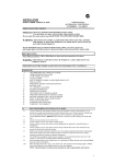
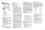
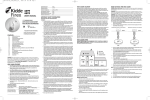
1004-7201-01(HA240)_V2:_
2010.9.2
9:20 AM
Page 1
MODEL HA240
FIXED TEMPERATURE DESIGN HEAT ALARM
INSTALLATION AND USER MANUAL
IMPORTANT! READ ALL INSTRUCTIONS BEFORE INSTALLATION AND
SAVE THIS MANUAL FOR FUTURE REFERENCE.
WARNING! THIS HEAT ALARM IS NOT DESIGNED AS AN EARLY WARNING
TO A FIRE BECAUSE IT DOES NOT DETECT SMOKE.
SEE LIMITATIONS OF THE HEAT ALARM IN SECTION 12 FOR
DETAILS
WARNING! REMOVAL OF HEAT ALARM BATTERY AND DISCONNECTING
OR LOSS OF AC POWER WILL RENDER THIS UNIT INOPERATIVE.
DO NOT TRY TO REPAIR THIS HEAT ALARM YOURSELF.
REFER TO INSTRUCTIONS IN SECTION 4 FOR MAINTENANCE.
CONTENTS
1.
2.
3.
4.
5.
6.
7.
8.
9.
10.
11.
12.
13.
14.
15.
16.
SPECIFICATIONS
RECOMMENDED LOCATIONS OF ALARMS
LOCATIONS TO AVOID
INSTALLATION INSTRUCTIONS
WIRING INSTRUCTIONS
MOUNTING INSTRUCTIONS
INSTALLING THE BASE PLATE
OPERATION
FALSE ALARMS
MAINTENANCE
CLEANING YOUR ALARM
LIMITATIONS OF HEAT ALARMS
GOOD SAFETY HABITS
WHAT TO DO WHEN THE ALARM SOUNDS
BCA REQUIRED PROTECTION
SERVICE AND WARRANTY
1. SPECIFICATIONS
240Vac 50Hz, 80mA max, 9V long life battery back up, single and or multiple station (24 units maximum).
The heat alarm is designed to activate at 73°C when the temperature range is between 58°C and 88°C.
Temperature rating -------------------- 73°C (163.4°F) Fixed temperature only
Maximum ambient -------------------- 88°C (190.4°F) temperature at heat alarm
Recommended coverage ---------------- 230 square metres (Note “A”)
Recommended spacing -------------------15.3 metres
Maximum distance from wall ----------------- 7.6 metres (Note “B”)
Note A: Maximum coverage is based on providing equal response time as sprinkler devices spaced at 3.0 metre
intervals (9.4 square metres) on a smooth ceiling approximately 4.6 metres high.
Higher ceilings may adversely affect response time and earlier response time may be obtained by
reducing the spacing between alarms.
Note B: Maximum distance is from any wall or ceiling projection extending down more than 30cm.
ELECTRICAL RATING: 240Vac, 50Hz, 80mA max per alarm with 24 alarms interconnected.
Interconnect compatible with smoke alarms of Models LIFESAVER LIF5000, LIF5800, LIF5800RL and
Lifesaver Visual Signalling Device SL240 And LANSON 240I, Isolation Relay LIFRK10A/9.
This Heat Alarm must only be wired to a 240Vac 50Hz sine wave current supply.
1
1004-7201-01(HA240)_V2:_
2.
2010.9.2
9:20 AM
Page 2
RECOMMENDED LOCATIONS OF ALARMS
2.1: Heat alarms give an audible warning when the temperature at the alarm reaches 73°C. Heat alarms are ideal
for kitchens, garages, cellars, boiler rooms, attics and other areas where there are normally high levels of
fumes, smoke or dust which preclude the use of smoke alarms due to the risk of false alarms. For normalsized
bungalows, two-story houses, flats and maisonettes, the PSA recommends that the minimum level of protection should comprise smoke alarms in the hallways and staircases. This minimum standard necessitates one
smoke alarm in the hallway of a typical bungalow or one smoke alarm on each level of a two-story house.
Heat alarms should not be used in these circulation areas. If there are, for example, long hallways, even the
minimum standard may necessitate additional interconnected smoke alarms. If, however, the design of the
dwelling does not comply with modern fire safety standards, or if factors such as the presence of several
young children, elderly occupants or disabled people, or smokers, the use of portable heaters or solid fuel fires
during the night, or the use of electric blankets, particularly by the elderly, PSA advises that additional detection devices, installed within rooms, may be necessary.
HEAT ALARM
IONISATION SMOKE ALARM
ATTIC
PHOTOELETRIC SMOKE ALARM
BEDROOM
BEDROOM
LIVING ROOM
KITCHEN
UTILITY/
LAUNDRY
GARAGE
2.2: The most favourable mounting location for a Heat
Alarm is on the ceiling and in the centre of the room.
At this location, the alarm is closest to all areas
of the room.
EXCEPTION : When the mounting surface
might become considerably warmer or
cooler than the room, such as a poorly
insulated ceiling, below an unfinished attic,
or an exterior wall. In these cases the alarm
should be mounted on an inside wall.
2.1: If the alarm cannot be located in the centre
of the room, an off-centre location can be
used on the ceiling. When off-centre
mounting an alarm on the ceiling, locate it
at a minimum of 300mm from the side wall (see diagram A)
Diagram A
2.4: If a ceiling mounting location is not possible, the next logical location for mounting
Heat Alarm is on the side wall. When mounting the alarm on the wall, use an inside
wall with the top edge of the alarm at a minimum of 300mm and a maximum of
600mm below the ceiling. (see diagram A)
2.5: When mounting the alarm on a sloping
ceiling, it should not exceed 1500mm away
from the apex. The spacing of additional alarms, if
any, should be based on a horizontal distance
measurement, not a measurement along the slope
of the ceiling (see diagram“B”)
Areas for
Heat Alarms
Diagram B
1004-7201-01(HA240)_V2:_
2010.9.2
9:20 AM
Page 3
2.6: In rooms with open joists or beams,all
ceiling mounted alarms shall be located on the
bottom of such beams.
(See diagram “C”)
2.7: Alarms installed on an open-joist ceiling
shall have the smooth ceiling spacing reduced
to no more than half of the listed spacing
when measured at right angles to the solid
joist. (See diagram “C”).
Diagram C
MOBILE HOME INSTALLATION
Mobile homes built in the past five years have been designed to be energy efficient. Install Heat Alarms as previously outlined (refer to RECOMMENDED LOCATIONS and diagram A). In mobile homes that are not well insulated compared to present standards, extreme heat or cold can be transferred from the outside to the inside through
poorly insulated walls and roof. This may create a thermal barrier which can prevent the heat from reaching an
alarm mounted on the ceiling. In such units, install the heat alarm on an inside wall with the top edge of the alarm at
a minimum of 300mm and a maximum of 600mm below the ceiling. (See diagram A).
If you are unsure about the installation in your mobile home, or if you notice that the outer walls and ceiling are either hot or cold, install the alarm on an inside wall.
3. WARNING ! LOCATIONS TO AVOID
3.1
3.2
3.3
In front of air ducts used for heating and air conditioning, near ceiling fans, or other high air flow areas.
In an area where the temperature may fall below 5°C (41°F) or rise above 88°C (190.4°F).
Near fluorescent lights - electronic “noise” may cause nuisance alarms.
4. INSTALLATION INSTRUCTIONS :
“PLEASE READ CAREFULLY”
4.1
4.2
4.3
This Heat Alarm should be installed with an AS approved junction box. All connections must be
installed by a qualified electrician and be in accordance with the relevant requirements of the SAA
Wiring Rules AS3000 Standards and / or any other codes having jurisdiction in your area.
The appropriate power source is 240Vac 50Hz continuous single phase sine wave current supplied from a
non-switchable circuit which is not protected by a RCD.
This Heat Alarm must be mounted at a minimum height of 2 metres.
5. WIRING INSTRUCTIONS: FOR A.C. QUICK CONNECT HARNESS
CAUTION ! ISOLATE MAIN POWER TO THE CIRCUIT BEFORE WIRING THE
ALARM.
5.1
5.2
5.3
For units that are used as single station, DO NOT CONNECT THE WHITE WIRE . Leave the
red wire insulating cap in place to make certain that the WHITE wire cannot contact any metal
parts.
When alarms are interconnected, all interconnected units must be powered from a single final sub
circuit.
A maximum of 24 devices may be interconnected only with smoke alarms of Models LIFESAVER
LIF5000, LIF5800, LIF5800RL, LANSD240I and Lifesaver Visual Signalling Strobe SL240.
2
1004-7201-01(HA240)_V2:_
2010.9.2
9:20 AM
Page 4
5.4
The maximum wire run distance between the first and last unit in an interconnected system is 307 metres.
Figure 1 illustrates interconnection wiring. Improper connection will result in damage to the alarm, failure
to operate, or electrical shock hazard.
5.6
Make certain alarms are wired to a continuous (non-switched) final sub-circuit.
Note: Use approved listed Australian Standards cable 1.0mm² TPS or larger as
required by local codes.
FIGURE 1 “INTERCONNECT WIRING DIAGRAM”
ALARM HARNESS --------------------CONNECTED TO:
BLACK
-------------------------------N
WHITE
-------------------------------SW
RED
-------------------------------A
FIGURE 1: TYPICAL DIAGRAM SHOWING INTERCONNECTION OPTIONS
FUSE OR CIRCUIT BREAKER
A
RED
WHITE
N
BLACK
A
RED
SW
N
WHITE
A
RED
BLACK
SW
N
WHITE
BLACK
A
RED
SW
N
WHITE
BLACK
6. MOUNTING INSTRUCTIONS
A trim ring is provided on the back of the Heat Alarm. This trim ring is removed by holding the trim ring and twisting the Heat Alarm in the direction indicated by the TURN TO REMOVE arrow. The trim ring is secured to the
heat alarm by a trim lever.
CAUTION ! THE COVER IS A SEALED UNIT AND HAS NO REMOVABLE
SERVICEABLE PARTS ! DO NOT TAMPER.
6.1
6.2
6.3
6.4
6.5
Secure a suitable junction box near the position of the Heat Alarm, ensure the quick connect cable length
is long enough to reach the junction box for termination to be made.
Connect Active, Neutral and Switch line to the Heat Alarm cable using the terminal connection block provided. Secure these terminals inside the junction box.
Punch out the suitable fixing holes on the trim ring and then pull the AC connector through the centre of
the trim ring.
Secure the trim ring to the ceiling using the fixing holes provided.Connect the 9V battery (back up) into
the battery compartment. Now, plug in the AC connector into the back of the Heat Alarm. Ensure the
locks on the AC connector snaps firmly into place.
Now mount the heat alarm onto the trim ring. Rotate the heat alarm until the heat alarm snap firmly into
place.
NOTE:PLEASE ENSURE THAT BATTERY IS INSTALLED PRIOR TO MOUNTING OF HEAT ALARM
Switch on the A.C. power and the green A.C. power ‘ON’ indicator should be lit. The Heat Alarm is now operating
on mains power.
3
1004-7201-01(HA240)_V2:_
2010.9.2
9:20 AM
Page 5
7. INSTALLING THE BASE PLATE
CONNECTOR
SQUEEZE
LOCKING
ARMS AND PULL
MARKS
REMOVE
INSTALL
FIGURE. 3
TAMPER RESIST
LOCKING PIN
FIGURE. 4
FIGUE 5
After installation TEST your alarm by pressing and holding the test button for several seconds. You can also use a
hand held hair dryer to test your heat alarm.
Complete details on this procedure are outlined in Section 8.
CAUTION ! Early warning fire detection is best achieved by the installation of smoke alarms in all rooms and areas
of the household as follows: A smoke alarm should be installed in each separate sleeping area (in the
vicinity of - but outside the bedroom) and heat or smoke alarm where appropriate in the living rooms,
dining rooms, kitchens, hallways, attics, furnace rooms, closets, utility storage rooms, basements, and
attached garages.
8. OPERATION
The Heat Alarm is operating once A.C. power is applied, new battery is installed and testing is complete. When
the Heat Alarm senses temperatures above 73°C (163.4°F) (plus or minus a few degrees), the horn will sound a loud
(85db) pulsating alarm until the temperature drops below 73°C (163.4°F). The heat alarm is designed to activate at
73°C when the temperature range is between 58°C(136.4°F) and 88°C(190.4°F).
FLASHING RED LED LIGHT: This Heat Alarm is equipped with a flashing Red LED. The LED is located under
the test button and has two functions.
1. Stand-by Condition---The Red LED will flash every 30-40 seconds to indicate that the Heat Alarm is operating
properly.
2. Alarm Condition ----When the unit detects heat and goes into alarm the red LED will flash rapidly ( 2-3
times per second ). The rapid flashing LED and pulsating alarm will continue until the
temperature drops below 73°C (163.4°F).
WHEN HEAT ALARMS ARE INTERCONNECTED with compatible Smoke Alarms, only the Red LED of the
originating unit will flash rapidly. All other units in the interconnect system will sound an alarm but their Red LED’s
will not flash.
TESTING: Test by pushing the test button on the cover and hold it down for a minimum of 5 seconds. This will
sound the alarm if all the electronic circuitry and horn are working correctly.
The test switch may not cause a test signal if the ambient temperature is below 8° C (20°F). In this
case, test the unit by blowing hot air at the alarm sensing element with a hair dryer held about
20cm from the unit.
If no alarm sounds, check the fuse or circuit breaker supplying power to the alarm circuit, if the alarm still does not
sound the unit may have defective battery or other failure.
IT IS RECOMMENDED TO TEST THE ALARM WEEKLY TO ENSURE PROPER OPERATION.
Erratic or low sound coming from your alarm may indicate a defective alarm, and it should be returned for service.
(SEE SECTION 16)
9. FALSE ALARMS
To avoid false alarms, DO NOT USE WHERE THE MAXIMUM ROOM TEMPERATURE WILL EXCEED 88°C .
Heat Alarms respond only to heat. They do not detect smoke. If the alarm does sound, check for fires first. If a fire is
discovered, get out of the house and call the Fire Brigade. If no fire is present, check to see if one of the reasons
listed in Section 2 may have caused the alarm.
4
1004-7201-01(HA240)_V2:_
2010.9.2
9:20 AM
Page 6
10. MAINTENANCE
10.1: ALARM REMOVAL:
Turn off the AC power supply to the heat alarm at the main distribution board. To replace the battery remove the
alarm from the trim ring by rotating the alarm in the direction of the TURN TO REMOVE arrow on the cover (see
Section 7 fig.4 and Section 10.2 fig 5).
To disconnect the A.C. power harness, squeeze the locking arms on the sides of the quick connector while pulling
the connector away from the bottom of the alarm (see Section 7, fig.3).
10.2: BATTERY INSTALLATION AND REPLACEMENT:
To replace or install the battery you must first remove the alarm from
the trim ring by following the ALARM REMOVAL instructions at the
beginning of this section. After alarm has been removed you can open
the battery door and install or replace the battery. Install the battery to
the battery terminal clip of the heat alarm. When installing the battery,
press the battery lever down into the battery compartment and install the
battery. (see fig.6).
CAUTION ! If the battery compartment is closed without a battery,
the red battery tamper will prevent the heat alarm
FIGURE.
from attaching to the trim ring. USE ONLY THE FOLLOWING 9Volt BATTERIES FOR HEAT ALARM REPLACEMENT:
Alkaline type:
EVEREADY 522, DURACELL MN1604 or MX1604
Lithium type:
ULTRALIFE U9VL-J
5
NOTE: REGULAR WEEKLY TESTING IS RECOMMENDED
WARNING!!! Use only the batteries specified. Use of different batteries may have a detrimental effect on the
alarm. Exposure to temperature extremes and / or high humidity may reduce battery life.
AFTER CLEANING, REINSTALL YOUR ALARM AND TEST YOUR ALARM BY USING THE TEST
BUTTON AND CHECK THAT THE GREEN LED IS ON.
11. CLEANING YOUR ALARM
Before cleaning the heat alarm, turn off the AC power supply to the heat alarm at the main distribution board. To
clean your alarm, remove it from the trim ring and disconnect the A.C. Quick Connect power harness as outlined in
the beginning of this section. You can clean your alarm by using a vacuum cleaner hose and vacuuming around the
heat sensing element and the perimeter of the alarm. The outside of the alarm can be wiped with a damp cloth.
We recommend a periodic monthly inspection and cleaning of the Heat Alarm to ensure proper operation.
AFTER CLEANING, REINSTALL YOUR ALARM AND TEST YOUR ALARM BY USING THE TEST
BUTTON AND CHECK THAT THE GREEN LED IS ON.
12. LIMITATIONS OF THE HEAT ALARM
Heat Alarms are not designed to protect life safely against fire and smoke. In most fires, hazardous levels of
toxic gases and smoke can build up before the heat alarm will operate. In cases where life safety is an issue,
Heat Alarms should only be used to provide an added source of protection and as a supplement to the smoke
alarm installation.
HEAT ALARMS DO NOT ALWAYS DETECT FIRES.
The fire may be a slow smouldering (smoke producing) and low heat producing type. The fire maybe in a
different room than the heat alarm, or the heat from the fire may bypass the alarm. This heat alarm will not
detect smoke, gases or flames.
Home fires develop in DIFFERENT ways and are often unpredictable. No one type of alarm (Heat,
Photo-electric or Ionisation) is always best, and a given alarm may not always provide warning of a fire. Also,
alarms do have limitations. Mains powered alarms may not operate if mains power has been cut off such as
by an electrical fire or an open fuse. Alarms must be tested regularly to make sure the batteries and the alarm
circuits are in good operating condition.
Heat Alarms cannot provide an alarm if heat does not reach the alarm. Therefore, heat alarms may not sense
fires starting in chimneys, walls, on roofs, on the other side of a closed door or on a different floor, it may not
wake up a sound sleeper. The use of alcohol or drugs may also impair one’s ability to hear the alarm. For
maximum protection heat alarms should only be used as a supplement to smoke alarms. Smoke alarms
should be installed in each sleeping area, on every level of a home and be interconnected with each other and
the heat alarms.
5
1004-7201-01(HA240)_V2:_
2010.9.2
9:20 AM
Page 7
13. GOOD SAFETY HABITS
DEVELOP AND PRACTICE A PLAN OF ESCAPE:
13.1
Make a floor plan indicating all doors and windows and at least two (2) escape routes from each room.
Second story windows may need a rope or escape ladder.
13.2
Have a family meeting and discuss your plan, showing everyone what to do in case of fire.
13.3
Determine a place outside your home where you can all meet if a fire occurs.
13.4
Familiarise everyone with the sound of the alarm and train them to leave home when they hear it.
13.5
Practice a fire drill at least every six months. Practice allows you to test your plan before an emergency.
You may not be able to reach your children. It is important they know what to do.
14. WHAT TO DO WHEN THE ALARM SOUNDS
14.1
Leave immediately by your escape plan. Every second counts, so do not waste time getting dressed or
picking up valuables.
14.2
In leaving, do not open any inside door without first feeling the surface. If hot, or if you see smoke seeping
through gaps, do not open that door! Instead use your alternate exit. If the inside of the door is cool, place
your shoulder against it, open slightly and be ready to slam it shut if heat and smoke rush in.
14.3
Stay close to the floor if the air is smoky. Breath shallowly through a wet cloth, if possible.
14.4
Once outside, go to your selected meeting place and make sure everyone is there.
14.5
Call the Fire Brigade from your neighbour’s home - not from yours !
14.6
Do not return to your home until the fire officials say that it is safe to do so.
There are situations where alarms may not be effective to protect against fire.
For instance:
a) smoking in bed
b) leaving children home alone
c) cleaning with flammable liquids, such as petrol
Further information on fire safety can be obtained from your local Fire Brigade.
15. BCA REQUIRED PROTECTION
Your local council can provide you with information regarding the legal requirement of fire protection equipment
for your home in accordance to the Building Codes of Australia (BCA). Wherever possible, ensure that you aim for
maximum protection by considering the use of additional smoke or heat alarms for increased coverage.
16. SERVICE & WARRANTY
If after reviewing this manual if you find that your heat alarm is defective in any way, do not tamper with the unit.
Return it to : PSA Products Pty Ltd 17 Millicent Street, Burwood, Victoria. 3125.
16.1
16.2
16.3
16.4
16.5
16.6
PSA Products Pty Ltd warrants that for two years from the date of purchase of the Heat Alarm, it will repair or replace the Heat Alarm (at the option of PSA Products Pty Ltd) due to any manufacturing defect,
at the cost of PSA Products Pty Ltd (excluding any labour costs relating to removal or re-installation of
product, and transport costs). This warranty does not extend to the battery.
This warranty shall not apply to the Heat Alarm if it has been damaged, modified, abused altered after the
date of purchase, or if it fails to operate due to improper use.
To the extent permitted by law, the liability of PSA Products Pty Ltd arising from the sale of this Heat
Alarm or under the terms of this limited warranty shall not in any case exceed the cost of replacement of
Heat Alarm and subject to this clause. In no case shall PSA Products Pty Ltd be liable for consequential
loss or damages resulting from the failure of the Smoke Alarm or for breach of this, or; Any other warranty, express or implied, loss or damage caused by failure to abide by the instructions supplied in this
manual.
To the extent permitted by law, PSA Products Pty Ltd, makes no warranty, expressed or implied, written or
oral, including that of merchantability or fitness for any particular purpose, with respect to the battery.
This warranty is in addition to and does not exclude the rights of consumers under the Australian Trade
Practices Act 1974, or any other law which may not be excluded.
To ensure quick and efficient warranty on this product; please register the details on our website.
www.psaproducts.com.au
There are a few important reasons to register your product:
1. It will ensure your investment is protected in case it is damaged or broken and we can effectively
carry out any warranty claims.
2. Registration will also allow us to contact you in an unlikely event of product safety notification
required under Consumer Product Safety Act.
3. Registration will also help us improve our product design to meet your needs.
For your convenience, register easily on-line on www.psaproducts.com.au
If you need any assistance, please contact us.
DEAR ELECTRICIAN:
PLEASE LEAVE THIS MANUAL FOR THE OWNER.
THANK YOU FOR CHOOSING THIS HEAT ALARM.
6
1004-7201-01(HA240)_V2:_
2010.9.2
9:20 AM
Page 8
AUSTRALIAN ELECTRICAL AUTHORITY - CS:SGSE/100434
Another Quality Product By:
PSA Products Pty Ltd
17 Millicent Street, Burwood 3125
Victoria, Australia
Telephone : (03) 9888 9889
Facsimile: (03) 9888 9993
E-mail: [email protected]
Website: http://www.psaproducts.com.au
N10116
1004-7201-01
7