1
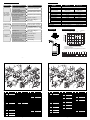
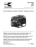
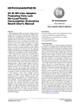
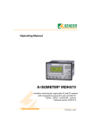
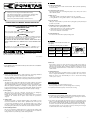
High Perfor mance Submersible Pump
PB SERIES OPERATION MANUAL
1. Leak Current Breaker
For home use, attach a leak current breaker, GFCI (offered separately)
to ensure safety.
2. Connect the power source
Absolutely refrain from connecting this pump to any other power source
than 110V AC, 50Hz.
Thank you for choosing Koshin Submersible Pump.
This manual is prepared for your safety when operating pump.
Please read carefully and comprehend fully before use.
(Wrong usage could cause injury or death.)
Please keep this manual handy for future reference.
PLEASE READ THIS MANUAL BEFORE OPERATION.
"ACCEPTABLE FOR INDOOR OR OUTDOOR USE"
"SUBMERSIBLE PUMP"
CAUTION
Before use, please make sure to read the instruction manual.
Do not operate the pump out of water or insufficient water.
3. Water to use
refrain from using the pump for any oil, sea water,
* Absolutely
strong alkaline or strong acidic solution, or any agricultural chemicals.
4. Do not run dry!
Idling can cause trouble, to prevent short cycling place pump at deepest
position as possible.
5. Handling of power cord (cabtype cable)
a. Never lift or move pump by power cord.
Only lift by handle or tie rope supplied to handle.
b. Select and use proper size extension cord.
Do not run extension cord in water.
6. Using in bath, etc.
Do not enter the water when pump is being used.
WARNING
Risk of electric shock. This pump is supplied with a grounding conductor
and grounding-type attachment plug. To reduce risk of electrical shock,
connect only to a properly grounded, grounding-type receptacle.
TO REDUCE THE RISK OF ELECTRIC SHOCK, INSTALL ONLY ON A
CIRCUIT PROTECTED BY A GROUND-FAULT CIRCUIT-INTERRUPTER
(GFCI).
NOTE
This pump has not been investigated for use in swimming pool or
marine areas. This pump has been evaluated for use with water only.
www.koshinpump.com
CAUTION
The pump is used a double mechanical seal.
(See figure)
Consulting the following table assemble it.
Outside
diameter
22.5mm
• An acceptable motor-control switch shall be provided at the time of installation.
Ther mally protected
INSTRUCTIONS FOR USE
1. Please check the type, aperture, output, frequency, and voltage indicated
on the name plate attached to the upper part of the pump.
Pay close attention, in particular, to frequency and voltage as inadequate
frequency and voltage can cause lower pump performance and troubles.
2. Place to use
The pump can be used at almost all places but avoid continuous short-water
operation at a sandy place, as such may accelerate wear of the pump.
Try to install the pump at a position where water can be collected most easily.
When the pump in installed on soft muddy or sandy ground, lay wooden
board or block under the body to prevent setting down. Strictly refrain from
putting into any pond bath, or swimming pool in which anybody is staying.
3. Hose piping
When any hose is used for connection, keep the hose as straight as
possible as excessively bent hose reduces water quantity.
Refrain from placing the discharge port under water Inverse flow may
sometimes be resulted due to siphon effect when the operation is
stopped.
4. Cabtire cable
To transfer the pump or to install, hold the pump on the handle or a rope
tied to the handle. If the cabtire cable is pulled instead of the rope, the
core wires may sometimes be cut off. To extend the cable, use a cable of
the same or larger size than the one attached to the pump. Strictly refrain
from placing the joint between the main line and the extension in water.
Pump
side
Carbon
18.5mm
15.0mm
Outside diameter
Carborundum
- 2 -
6. After use
If the pump is left as it is after used for water of high sand content or
other special substances, the sand is accumulated in the pump and will
affect the next operation. Before stopping operation, therefore, be sure to
keep pumping supernatant water or clean water for some time to clean
out the inside.
7. Thermal protector
The pump incorporates a thermal protector to protect the motor, and the
motor is stopped automatically at a over-load operation due to any reason.
When the motor stops automatically, be sure to check after turning
off the power source.
AFTER USING PUMP
1. In cold climates, do not allow pump to freeze.
Remove pump from water to prevent damage due to freezing.
2. Completely drain and dry pump of water before storing.
MAINTENANCE AND INSPECTION
1. Periodically check the insulated condition with a insulation resistance tester.
To be acceptable, the resistance between the ear thing wire and the
power cord should be 100Meg ohm and higher
2. The shaft of the water-tight mechanism as the most critical par t of the
pump is sealed with liquid paraffin. The life changes greatly depending on
the operating condition but the quantity should be checked periodically.
Use 170cc of Crystol No.70 by Exxon Mobil Corporation for the sealing.
The liquid paraffin can be checked easily by removing the hexagon
socket head bolt at a side of the pump body.
5. Earth leakage breaker
Be sure to ground the earthing wire before connecting the cabtire cable
to the power source. The green wire is for earthing. Be sure to attach the
leakage breaker to prevent any possible leakage trouble.
- 3 -
Motor
side
20.5mm
09-07 043047003
INSTALLATION AND USE
Double mechanical
Internal diameter
Mechanical Motor side
Plum side
seal
(Carbon) (Carborundum)
Internal
diameter
12 Kami-Hachinotsubo Kotari, Nagaokakyo City, Kyoto 617-8511 JAPAN
TEL.+81-75-954-6111 FAX.+81-75-954-6119
- 1 -
CAUTION
- 4 -
TROUBLESHOOTING GUIDE
Failure during
operation
Not properly connected
to power circuit
Correct the connection
The GFCI, leakage
circuit breaker is actuated
Check the power circuit
The impeller is caught
by foreign substance
Repair the point of leakage
Motor is burnt
Repair or replace
Voltage drop
Raise the voltage to
the rating
Remove foreign substance
if the impeller is clogged
The protector is actuated
Lower the liquid
temperature if it is too high
Lower the head
Discharge pipe is clogged
Overhauling
Impeller wear
Replacement
Clogging of foreign
matter in strainer pump
Overhauling
Delivery Volume
*Starting current is three times higher than rated current.
DIMENSION
H
PERFORMANCE CURVE
20
I
40
(USG/min)
80
60
20
G
No pumping
or poor
performance
High delivery head
PB7-65011
2" (50 mm)
32.8 ft (10 m)
55.7 ft (17 m)
76.6 USG/min
89.8 USG/min
(290 L/min)
(340 L/min)
Single AC-110V
60 Hz
8.7 A
12 A
400 W
750 W
750 W
1.25kW
3400 rpm
Induction Motor
19.7 ft (6 m)
32.8 ft (10 m)
1 Rope 5 m, 1 Hose Band
35 lbs (16.7 kg)
42 lbs (19 kg)
Voltage
Frequency
Rated Current
Output
Consumption
Revolution
Model
Power Cord
Standard Accessories
Net Weight
Raise the voltage to
the rating
Voltage drop
PB-65011
MODEL
Connection Dia
Total Head
PUMP
SOLUTION
TOTAL HEAD (m)
No start at
all or stops
immediately
after start
POSSIBLE CAUSE
MOTOR
PROBLEM
SPECIFICATIONS
F
Unit: mm
(ft)
60
15
PB7-65011
40
10
30
20
5
E
10
PB-65011
0
B
J
50
100
200
300
DELIVERY VOLUME (L/min)
* Performance ratings are guaranteed minimum,
C
A
not inflated maximum.
** Starting current is three times higher than rated current.
Unit: mm
MODEL
A B C
PB-65011 398 72 326
PB7-65011 384 52 332
D
- 5 -
D
E
F
G H I J
181 NPT 6000
84 43 44 74
193 2" 10000
- 6 -
PARTS LIST
PARTS LIST
40
35
16
35
15
30
52
10
47
59
14
56
13
26
12
54
27
11
51
21
5
25
25
60
17
11
10
61
39
56
51
31
19
48
44
31
26
41
12
33
27
58
23
18
43
45
18
12
19
8
3
8
1
1 0438135
0430465
0430001
0430452
0430453
0430004
0430003
0430002
9 0430022
10 0390002
0390142
893555043
0390141
888727008
15 0390001
16 707825018
17 708119037
18 0390079
PARTS NAME
QTY
PB-5011 Motor
1
Set.(2~27 set)
PB-50 Motor Frame 1
PB-50 Bearing Plate 1
PB-50 Head Cover 1
PB-50 Front Bracket 1
PB-50 Frame Packing 1
PB-50 Head Packing 1
2
PB-50 Spacer
PB-40 Centrifugal
1
Force Switch-cover
Condenser
1
(125VAC 150µF)
1
Band
2
Oil Seal
1
Toothed Washer
1
Stop Ring
PS-40 Centrifugal
1
Force Switch
Screw (M3×6 BS) 2
Screw
2
(M4×10 SWRM)
PS-5010 Terminal
1
Protector (Spec. 110V)
3
37
52
2
20
PB-65011
No. PARTS CODE
40
9
28
38
13
29
37
49
17
14
57
2
25
33
53
25
29
42
54
22
50
39
38
30
34
15
28
55
44
36
13
20
32
11
12
13
14
56
24
49
2
3
4
5
6
7
8
34
4
41
36
53
16
9
4
46
46
45
21
9
6
7
51
50
8
20
55
6
7
22
5
24
23
1
32
PB7-65011
No.
19
20
21
22
23
24
25
26
27
PARTS CODE
708219042
0430043
0430023
857627023
0430082
0430026
0430073
0340142
0340153
28 0390037
29
30
31
32
33
34
35
36
37
38
39
40
854255010
0430484
703305102
0390031
0260137
703305100
0430008
0430013
0430454
0430463
889955100
0430025
PARTS NAME
QTY
Screw (M4×25 SWRM) 2
Screw (M4×145 SUS) 4
PB-50 Supporter
1
Wave Washer
1
Washer
1
Bearing Washer
1
Screw (M4×6 SWRM) 5
SM Seal Ring
1
SM Screw (M6×8 SUS) 1
PS Socket Bolt
1
(M10×12 SUS)
Seal Washer
1
Power Cord (PB-65011) 1
Screw (M5×14)
2
PS-40 Cord Supporter 1
BL-3224 Cord Band 1
Screw (M5×10 SUS) 1
PB-50 Out Cover
1
PB-50 Out Packing 1
PB-50 Casing
1
PB-50 Unified Strainer 1
O Ring (G100)
1
PB-50 O Ring ( 166) 1
-7-
No.
41
42
43
44
45
46
49
50
51
52
53
54
55
56
57
58
PARTS NAME
PARTS CODE
0430014 PB-50 Stud Bolt
0390712 PS-40 Suction Cover
0390019 PS-40 Suction Packing
PS-50-60Hz Impeller
0390725
(PB-65011)
0390025 Impeller Adjusting Washer
0430464 PB-50 Press Handle
708105056
Screw (M6×16 SUS)
0430150 Label
0430243 Mechanical Seal
0390092 PS-50 Flange Packing
884205023 Key
845205010 Toothed Washer
827405010 Nut (M10)
827405008 Nut (M8)
0430074 PB-50 Sleeve
0430044 Socket Bolt
59 0430143
PB-50 NPT
Delivery Flange
60 747805028 Bolt (M6×12 SUS)
61 827305005 Nut (M5)
QTY
3
1
1
1
0~3
1
2
1
1
1
1
1
1
5
1
3
No. PARTS CODE
1 0438048
2
3
4
5
6
7
8
0430478
0430462
0430452
0430220
0430004
0430003
0430294
9 708119039
10 0430295
11 708119041
12 0430296
13 893555043
14 0430293
1
4
1
15 0430043
16 0430231
17 857627023
18 0430082
PARTS NAME
QTY
PB7-5011 Motor
1
Set. (2~22 set)
PB-50 Motor Frame 1
PB-50 Bearing Plate 1
PB-50 Head Cover 1
PB7 Front Bracket 1
PB-50 Frame Packing 1
PB-50 Head Packing 1
PB-50 Spacer (L=5) 3
Screw
3
(M4×14 SWRM)
PB-50 Spacer (L=10) 1
Screw
1
(M4×20 SWRM)
Condenser
2
(250VAC 32µF)
Oil Seal
2
PB7-5011
1
Terminal Protector
Screw
4
(M4×145 SUS)
PB7 Supporter
1
Wave Washer
1
Washer
1
No. PARTS CODE
PARTS NAME
QTY
19 0430026 Bearing Washer
1
Screw
20 0430073
3
(M4×6 SWRM)
21 0340142 SM Seal Ring
1
SM Screw
22 0340153
1
(M6×8 SUS)
PS Socket Bolt
23 0390037
1
(M10×12 SUS)
24 854255010 Seal Washer
1
Power Cord
25 0430232
1
(PB7-65011)
26 703305102
2
Screw (M5×14)
PS-40
27 0390031
1
Cord Supporter
28 0260137 BL-3224 Cord Band 1
Screw
29 703305100
1
(M5×10 SUS)
30 0430008 PB-50 Out Cover
1
31 0430013 PB-50 Out Packing 1
32 0430223 PB-50 Casing
1
33 0430225 PB7 Strainer
1
34 889955100 O Ring (G100)
1
35 890155150 O Ring (S150)
1
36 0430253 PB7 Stud Bolt
3
- 8 -
No.
37
38
39
PARTS NAME
PARTS CODE
0430226 PB7 Suction Cover
0430227 PS7 Suction Packing
0430234 PB7-60Hz Impeller
Impeller Adjusting
40 0390025
Washer
41 0430464 PB-50 Press Handle
44 708105056
45 0430276
46 0390003
47 0390092
48 884205023
49 845205010
50 827405010
51 827405008
52 0430074
53 0430044
Screw
(M6×16 SUS)
Label
Mechanical Seal
PS-50 Flange Packing
Key
Toothed Washer
Nut (M10)
Nut (M8)
PB-50 Sleeve
Socket Bolt
54 0430143 PB-50 NPT
Delivery Flange
55 747805028 Bolt (M6×12 SUS)
56 827305005 Nut (M5)
QTY
1
1
1
1
1
2
1
1
1
1
1
1
5
1
3
1
4
1