1
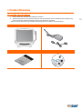
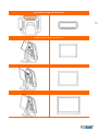
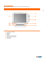
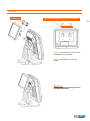
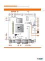
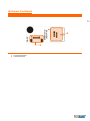
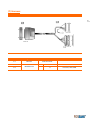
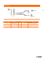
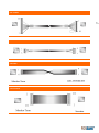
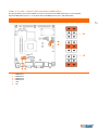
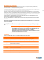
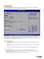
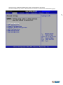
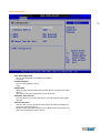
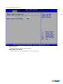
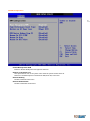
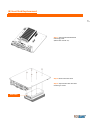
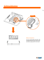
PBUM-005E(Rev001;130322)
Point-of-sale system
AnyShop D5
User’s manual
-Table of ContentsPOSBANK USER’S MANUAL REVISION HISTORY.................................................................................................................................................................. 4
PREFACE ......................................................................................................................................................................................................................................... 5
SYMBOL; MARK ........................................................................................................................................................................................................................... 6
COPYRIGHT ................................................................................................................................................................................................................................... 7
WARRANTY ................................................................................................................................................................................................................................... 8
SAFETY INSTRUCTIONS ............................................................................................................................................................................................................ 9
NOTICE ........................................................................................................................................................................................................................................ 10
LIABILITY LIMITATION ............................................................................................................................................................................................................ 11
INSTALLATION RECOMMENDATIONS .............................................................................................................................................................................. 12
1.PRODUCTOVERVIEW...................................................................................................................................................................... 13
(1) INSIDE YOUR PACKAGE ................................................................................................................................................................................................................................ 13
(2) PRE-INSTALLATION PREPARATION ........................................................................................................................................................................................................... 15
(3) PRODUCT OUTLINE ....................................................................................................................................................................................................................................... 15
(4) CONFIGURATION ............................................................................................................................................................................................................................................ 16
(5) I/O PORT: DETAILS .......................................................................................................................................................................................................................................... 18
(6) INSTALLATION OF OPTIONAL DEVICES: 2ND DISPLAY ..................................................................................................................................................................... 19
(7) SETTING UP: KEYBOARD & MOUSE CONNECTION ............................................................................................................................................................................ 21
(8) SETTING UP: CONNECTION USB PORT ................................................................................................................................................................................................... 22
(9) SETTING UP: CONNECTION VIA ETHERNET PORT (LAN) .................................................................................................................................................................. 23
(10) SETTING UP: LINE-OUT, MIC-IN, LINE-IN CONNECTION ................................................................................................................................................................. 24
(11) SETTING UP: POWER CABLE CONNECTION ....................................................................................................................................................................................... 25
(12) SWITCHING ON POS.................................................................................................................................................................................................................................... 26
(13) SHUTTING DOWN POS .............................................................................................................................................................................................................................. 27
(14) SYSTEM DRIVERS .......................................................................................................................................................................................................................................... 28
2.MOTHERBOARD ............................................................................................................................................................................ 29
(1) MOTHERBOARD OVERVIEW ....................................................................................................................................................................................................................... 29
(2) MOTHERBOARD LAYOUT............................................................................................................................................................................................................................. 30
(3) SIDE USB BOARD ............................................................................................................................................................................................................................................ 32
(4) POWER SWITCH BOARD............................................................................................................................................................................................................................... 33
(5) DRAWER KICKER BOARD.............................................................................................................................................................................................................................. 34
(6) DRAWER PORT BOARD ................................................................................................................................................................................................................................. 35
(7) HARNESS............................................................................................................................................................................................................................................................ 36
(8) JUMPERS ............................................................................................................................................................................................................................................................ 45
3.BIOSSETUPUTILITY......................................................................................................................................................................... 48
(1) MANAGING AND UPDATING YOUR BIOS .............................................................................................................................................................................................. 48
(2) BIOS SETUP PROGRAM................................................................................................................................................................................................................................. 49
(3) MAIN SETUP...................................................................................................................................................................................................................................................... 51
4.TROUBLESHOOTING ....................................................................................................................................................................... 70
(1) NETWORK ISSUES ........................................................................................................................................................................................................................................... 70
(2) MSR ISSUES ....................................................................................................................................................................................................................................................... 70
(3) USB ISSUES........................................................................................................................................................................................................................................................ 70
(4) LCD ISSUES........................................................................................................................................................................................................................................................ 70
(5) TOUCH-SCREEN ISSUES................................................................................................................................................................................................................................ 71
(6) POWER ISSUES................................................................................................................................................................................................................................................. 71
(7) PS/2 KEYBOARD ISSUES ............................................................................................................................................................................................................................... 71
(8) BOOTING ISSUES............................................................................................................................................................................................................................................. 71
5.MAINTENANCE .............................................................................................................................................................................. 72
ANYSHOP MODULE POS SYSTEM REPLACEMENT.................................................................................................................................................................... 73
(1) SEPARATING LCD MODULE......................................................................................................................................................................................................................... 73
(2) SEPARATING MSR MODULE ........................................................................................................................................................................................................................ 76
(3) SEPARATING HINGE MODULE .................................................................................................................................................................................................................... 77
(4) SEPARATING BACK COVER .......................................................................................................................................................................................................................... 78
(5) SEPARATING CUSTOMER DISPLAY(CDP)................................................................................................................................................................................................ 79
(6) SEPARATING MOTHERBOARD.................................................................................................................................................................................................................... 80
(7) MOTHERBOARD REPLACEMENT ............................................................................................................................................................................................................... 80
(8) HEAT SINK REPLACEMENT .......................................................................................................................................................................................................................... 80
(9) MEMORY REPLACEMENT............................................................................................................................................................................................................................. 80
(10) SEPARATING USB PCB................................................................................................................................................................................................................................. 89
(11) SEPARATING SSD .......................................................................................................................................................................................................................................... 90
SPECIFICATION ............................................................................................................................................................................ 91
2
Copyright© POSBANK Co., Ltd. All rights reserved.
Specifications and information contained in this manual are furnished for informational use only, and are subject
to change at any time without notice.
The information contained in this document is subject to change without notice.
We make no warranty of any kind with regard to this material, including, but not limited to, the implied warranties
of merchantability and fitness for a particular purpose. We shall not be liable for errors contained herein or for
incidental or consequential damages in connection with the furnishing, performance, or use of this material.
This document contains proprietary information that is protected by copyright. All rights are reserved.
No part of this document may be photocopied, reproduced or translated to another language without the prior
written consent of the manufacturer.
3
POSBANK User’s manual Revision History
Changes to the AnyShop D5 User’s manual are listed below.
Rev No.
Revision History
Date /author
PBUM-005E(Rev001;130322)
New
2013.03.22
4
Preface
This User's Guide gives information about main unit/IO port layout, basic setup, component installation, and
board layout for point of sale system "AnyShop"
Intended Audience
The User's Guide is intended for technically qualified personnel.
It is not intended for general audiences.
Document Organization
The chapters in this Product User’s manual are arranged as follows:
1.
2.
3.
4.
5.
6.
product package contents
system configuration
Harness (cable connector)
BIOS Setup
Installing and Replacing POS SYSTEM Components: instructions on how to install the motherboard and
other POS hardware components.
Product specification
5
SYMBOL; MARK
CE MARK
This device complies with the requirements of the EEC directive 2004/108/EC with
regard to “Electromagnetic compatibility” and 2006/95/EC “Low Voltage Directive”.
FCC
This device complies with part 15 of the FCC rules. Operation is subject to the
following two conditions:
(1) This device may not cause harmful interference.
(2) This device must accept any interference received, including interference
that may cause undesired operation.
KC
Korea Certification mark.
Certificate No. PBS-AnyShop-D5(A)
Recycling and disposal of electric and electronic devices and their components
This product should not be mixed with other commercial wastes for disposal.
6
Copyright
This publication, including all photographs, illustrations and software, is protected under international copyright
law with all rights reserved to the manufacturer. Neither this manual, nor any of the material contained herein,
may be reproduced without express written consent of the author.
AnyShop and POSBANK are trademarks of POSBANK Co., Ltd. in the United States and other countries.
* Other names and brands may be claimed as the property of others.
Copyright© POSBANK Co., Ltd. All rights reserved.
7
Warranty
We guarantee our POS terminal product and its parts against defects in materials and workmanship, under
proper use, for a standard period of 2 years from the original date of purchase.
During this period, we will repair or replace defective and/or faulty products or parts without charge to the
customer for parts and labor.
The 1st year includes servicing and new or refurbished replacement parts free of charge, with one-way shipping
costs borne by the seller. The customer shall, however, be responsible for the return delivery costs. The 2nd year
also includes free of charge servicing and parts, but a limited warranty requires the entire shipping cost to be
borne by the customer.
Products out of the warranty period or scope shall be diagnosed at the customer's expense.
In the case of product damage due to error on part of the consumer, incorrect usage, carelessness or natural
phenomenon, the customer shall bear the full cost for both repair and delivery.
8
Safety Instructions
1.
To disconnect the machine from the electrical power supply, turn off the power switch and remove the
power cord plug from the wall socket.
2. The wall socket must be easily accessible and in close proximity to the machine.
3. Read these instructions carefully. Save these instructions for future reference.
4. Follow all warnings and instructions marked on the product.
5. Do not use this product near water.
6. Do not place this product on an unstable cart, stand, or table. The product may fall, causing serious
damage to the product.
7. Slots and openings in the cabinet and the back or bottom are provided for ventilation to ensure reliable
operation of the product and to protect it from overheating. These openings must not be blocked or
covered.
8. The openings should never be blocked by placing the product on a bed, sofa, rug, or other similar
surface.
9. This product should never be placed near or over a radiator or heat register or in a built-in installation
unless proper ventilation is provided.
10. Never push objects of any kind into this product through cabinet slots as they may touch dangerous
voltage points or short out parts that could result in a fire or electric shock. Never spill liquid of any kind
on the product.
9
Notice
1.
2.
3.
4.
5.
6.
7.
8.
9.
Always ensure that the correct power voltage is used as a precaution against fire and electrical shock.
Avoid exposing product to direct sunlight. Do not use product in areas of high humidity.
Doing so may cause low reliability and/or operational malfunction.
Be careful of static electricity on PCB of system with anti-static appliances. Doing so may cause inferior
reliability and shorted product life.
Keep product away from highly static areas. This may lead to inferior performance and reduced life cycle.
Do not interfere with, or obstruct metal components inside product. Doing so may cause the risk of fire
or electric shock.
Do not pull on power cable or peripheral devices’ connector cable. Doing so may cause fire, electric
shock or electronic system malfunction.
Use caution when around other electronic devices with possible high frequency or electro-magnetic
effects e.g. Audio, Electronic-range etc. Doing so will lead to the serious risk of product malfunctioning
or a system error occurring.
Ensure that batteries are replaced correctly. Failure to do this may result in sudden explosions.
Dispose of used batteries properly according to the instructions.
10
Liability Limitation
● Installation and maintenance
We recommend that you inquire about product installation, maintenance and repair service from the official
service center and agent office.
POSBANK takes no responsibility for malfunctions or system errors occurring after service and/or system check
carried out by unofficial service providers.
● High frequency appliances
This product is qualified by FCC, CE and KC compliances, and is thus governed by these qualifications’ safety
regulations.
However, the product can affect and be affected by other high frequencies generated around it. As such,
POSBANK does not consider liability for any system error or disorder due to this issue.
● Electronic noise emitting equipment
We recommend using the product away from electronic noise emitting equipment such as heaters, motors,
fluorescent lights, TVs etc. as it may cause interruption or interference with normal operation.
● Installation location
For optimal performance, the product should be kept in an environment of lower than 65% humidity and in a
temperature of 10 ~ 30℃. Please also keep away from direct sun-light.
● Cleaning procedure
Cleaning with chemical based products (in particular those containing benzyl or chemical thinning agents) can
damage the exterior surfaces of the product. We recommend using a soft damp cloth and wiping gently, taking
particular care when dealing with the LCD display screen.
● Product limitations
1. The use of this product for anything other than POS tasks is strictly prohibited.
The product is not supported for regular PC and interface operation.
2. This product is for business use only, and not for usage in the home.
3. Both hardware and software are both fully configured.
4. Normal operating is guaranteed on a steady power connection.
11
Installation Recommendations
1.
2.
3.
4.
5.
6.
7.
Avoid installing during thunderstorms. (Possibility of dangerous exposure to electricity.)
Install away from damp spaces or water-leaks.
Beware of static occurrence during installation.
Use only ground connected and quality certified power cords and cables.
Keep out of direct sun-light, extremely high or low temperatures, or high humidity areas.
Install product away from areas prone to shocks or vibration.
Install product away from sewing machines, welding equipment, electric stoves, audio equipment and
other high frequency generating equipment.
8. Installation and use in close proximity to an air-conditioning unit is not recommended.
9. Do not connect cables underneath carpets or floorboards.
10. Only use power cables supplied by pre-approved and certified venders.
11. Never use power cords from high power source appliances.
e.g. Electronic heaters, Electric stoves, Audio equipment, Air-conditioners, Refrigerators etc.
12. The use of multiple connections in a shared power outlet/socket is not recommended.
12
1. Product Overview
(1) Inside Your Package
1.
2.
Please check your package and confirm its contents.
The POS terminal main unit, power cable, user manual and driver CD are included in the package. If any
items are missing or damaged, please contact your dealer for assistance.
» All user manuals and drivers are available for download on our website: www.easyset.org
AnyShop Main unit
Adapter / Power cord
Installation guide
Drivers CD
13
Optional Devices: CDP (Customer display)
14
Optional Devices: 2nd LCD monitor 10.1”
Optional Devices: 2nd LCD monitor 12.1”
Optional Devices: 2nd LCD monitor 15.1”
(2) Pre-installation Preparation
1.
2.
Remove protective film from touch-screen to prevent possible operating difficulties.
Attach all optional parts before setting up the main POS unit.
(3) Product Outline
•
•
Each part of product may differ depending on the specific POS model.
Model-specific data sheets are provided on our website at www.easyset.org
15
(4) Configuration
Refer to following diagram to identify the components on this side of the system.
Front view
16
5
5
1
6
1
6
7
7
2
2
3
3
4
4
1.
2.
3.
4.
5.
6.
7.
8.
9.
LCD & Touch panel display
Power LED
HDD LED
LAN LED
Camera
Smart card reader(SCR); Option
Magnetic stripe reader(MSR)
Power switch
Dual speaker
8
9
Rear view
3
4
5
1
2
2
1.
2.
3.
4.
5.
USB port
I/O port
Customer display; Option
HDD
Stand
17
(5) I/O port: Details
* I/O ports may differ according to product model or options.
I/O view
18
6
2
7
1.
2.
3.
4.
5.
6.
7.
Power connector
Cash box port
COM1, COM2, COM3 port
VGA port
USB x 2 Ports
LAN Ports
LPT port
1
3
4
5
(6) Installation of Optional Devices: 2nd Display
* The assembling method of the 2nd Display is equal for all the products. (10.1, 12.1, 15 inch)
2nd Display
19
* Warning: Completely remove power cable
when opening main unit or installing
optional devices.
Step 1. Assemble the 2nd MONITOR HINGE
using four bolts.
HINGE LOWER
Step 2. Assemble the HINGE LOWER using
one bolts.
2nd display
2nd LCD cap
When assembling, put the grooves on the bottom.
20
Step 3. Fix with four bolts, after Place the
2nd MONITOR on the HINGE.
Step 4. Fix the HINGE CAP using the
HOOK.
※
Beware of the parts where grooves are
located at the bottom.
(7) Setting up: Keyboard & Mouse Connection
Connecting the keyboard and mouse to the PS/2 port on the bottom panel.
or connecting the USB type keyboard and mouse to the USB port on the bottom panel.
21
(8) Setting up: Connection USB Port
USB ports are provided in the POS unit, two at the rear I/O and two at the side, all of which support the standard
USB 2.0.
Some USB devices (optional devices) are only functional with specific driver software installed.
If multiple USB devices are used together, this may result in abnormal functionality.
Using a USB hub with external adapter for supplying power is recommended.
Dependent on the type of device, it is possible for the USB device to be recognized later than normal.
USB port (3port support)
22
(9) Setting up: Connection via Ethernet Port (LAN)
The Ethernet port located at the rear I/O supports 10/100/1000Mbps using an RJ45 connector cable.
When connected properly, the LAN LED light will be switched on.
Through a network hub.
Refer to the table below for the LAN port LED indications.
23
LINK/ACT LED
SPEED LED
LINK / ACT LED
SPEED LED
Status
OFF
YELLOW
BLINKING
Status
OFF
ORANGE
GREEN
Description
No link
Linked
Data activity
Description
10Mbps connection
100Mbps connection
1Gbps connection
(10) Setting up: Line-out, Mic-in, Line-in connection
•
•
•
Line In port (light blue): This port connects a tape, CD, DVD player, Sources.
Line Out port (lime): This port connects a headphone or a speaker.In4-channel, 6-channel and 8channel configuration, the function of this port becomes Front Speaker Out.
Microphone port (pink): This port connects a microphone.
24
(11) Setting up: Power Cable Connection
The ‘AnyShop D5’ POS system is equipped with a 12V, 5A power adaptor.
Connect the cable to the DC-IN port on system IO panel.
25
CAUTION : Do not pull on the adaptor cable! Disconnect cable with pulling the plug cap.
(12) Switching On POS
1.
2.
Press POWER button on the POS unit. (POWER LED will light up.)
The power switch is located right hand side of the main body under the display unit.
Confirm that Windows loads correctly.
26
(13) Shutting Down POS
* For product stability, we recommend closing Windows from the O/S. Please make sure that you have closed all
applications before closing Windows.
1.
2.
Click ‘Start’ and select ‘Turn off Computer’
Click ‘Shut Down’ to close Windows.
27
(ex: POSReady2009 or Windows XP)
2
1
(14) System Drivers
Please visit our website: www.posbank.com for the latest driver updates.
Supported devices: Cash drawer, CDP (Customer Display Panel), MSR (Magnetic Swipe Reader) and printer.
Driver installation
● Installation method :
Driver will automatically install by clicking SETUP.EXE in your driver CD.
If you require any help with installing or using our OPOS system, please contact our customer service center.
● Folder of contents of POS terminal installation driver:
1. CHIP SET DRV installation
2. VIDEO (VGA) DRV installation
3. TOUCH DRV installation
4. AUDIO DRV installation method
5. LAN DRV installations
6. AMT & ME Driver installation
7. User’s Manual, Installation guide
28
2. Motherboard
(1) Motherboard Overview
This includes description of the jumpers and connectors on the motherboard.
Warring
Take note of the following precautions before you install motherboard components or change any motherboard
settings.
1. Unplug the power cord from the wall socket before touching any component.
2. Before handling components, use a grounded wrist strap or touch a safely grounded object or a metal
object, such as the power supply case, to avoid damaging them due to static electricity.
3. Hold components by the edges to avoid touching the ICs on them.
4. Whenever you uninstall any component, place it on a grounded antistatic pad or in the bag that came
with the component.
5. Before you install or remove any component, ensure that the ATX power
6. Supply is switched off or the power cord is detached from the power supply. Failure to do so may cause
29
(2) Motherboard Layout
This includes description of the jumpers and connectors on the motherboard.
Motherboard view
30
NO Description
1.
SATA_PWR_CN2
2.
SATA 2
3.
SATA 1
4.
SATA_PWR_CN1
5.
J1
6.
J2
7.
Mini PCIe slot
8.
COM 6
9.
COM 5
10. JCOMPWR2
11. JCOMPWR3
12. JCOMPWR1
13. COMPSEL5
14. CN15
15. COMPSEL4
15-1. JAMP1
16. COM 4
16-1. COMPSEL6
NO Description
17.
18.
19.
20.
21.
22.
23.
24.
25.
26.
27.
28.
29.
SYS_FAN
CPU_FAN
COMPSEL3
VGA 1
LVDS1
CN29(12V DC)
CN30(24V DC)
COMP1SEL2
COMP1SEL1
VP1(Inverter)
F-Panel1
GPIO1
CMOS1
31
(3) Side USB Board
Side USB Board Connector Description
32
A
A. To Motherboard USB
(4) Power Switch Board
Power Switch Board Connector Description
33
A
A. Power switch
(5) Drawer Kicker Board
Drawer Kicker Board Connector Description
B
34
C
A
A. Drawer Port
B. Serial Port
C. Mini PCIe Slot
(6) Drawer Port Board
Drawer Port Board Connector Description
35
B
A
A. From Drawer Kicker
B. Cash Drawer port
(7) Harness
# 201 Cable view
36
#201-1 Cable
System
Connector
P-1
Monitor
SCSI Connector
P-2
P-3
Motherboard
Note
LVDS1
LVDS
J1
Inverter, Touch, MSR
#208-1 J2 Cable
37
#208-1 J2 Cable
System
Connector
P-1
Motherboard
P-2
Side USB
A
USB ports
P-3
PB-56 Power sw
A
Power switch
J2
Note
Power switch, Side USB
#83-3 Speaker cable view
38
#83-3 Cable
System
P-1
Motherboard
Connector
JAMP1
Note
Audio
#138-1 HDD power cable view
#138-1 Cable
System
Connector
P-1
Motherboard
SATA PWR CN1
P-2
HDD
SATA Power
Note
#198-1 SATA Data cable view
39
#198-1 Cable
System
Connector
P-1
Motherboard
SATA DATA I
P-2
HDD
SATA DATA
Note
SATA 1
#177-2 2ndDisplay cable
40
#177-2 Cable
System
Connector
P-1
Motherboard
VGA1
P-2
Motherboard
VP1
P-3
Motherboard
COM4
P-4
2nd Diaplay
Note
2nd Display Power
2nd Display or CDP
Monitor Harness
41
Label
Description
Label
Description
A
27-3
LVDS
C
207
LED
B
19-1
Touch
D
137
Inverter
#27-3 LVDS
42
#19-1 Touch
#207 LED
#137 Inverter
2nd Monitor Harness
43
Label
Description
A
6-2
Inverter
B
27-1
LVDS
Label
C
Description
32-3
VGA & 12V DC
#6-2 Inverter
44
#27-1 LVDS
#32-3 VGA, 12V DC
(8) Jumpers
Clear RTC RAM (CLRTC)
This jumper allows you to clear the Real Time Clock (RTC) RAM in CMOS. You can clear the CMOS memory of date,
time, and system setup parameters by erasing the CMOSRTC RAM data. The onboard button cell battery powers
the RAM data in CMOS, which include system setup information such as system passwords.
To erase the RTC RAM:
1. Turn OFF the computer and unplug the power cord.
2. Remove the onboard battery.
3. Move the jumper cap from pins 1-2 (default) to pins 2-3. Keep the cap on pins 2-3 for about 5~10
seconds, then move the cap back to pins 1-2.
4. Re-install the battery.
5. Plug the power cord and turn ON the computer.
6. Hold down the <Del> key during the boot process and enter BIOS setup tore-enter data.
CAUTION: Except when clearing the RTC RAM, never remove the cap on CLRTC jumper default position.
Removing the cap will cause system boot failure!
Clear RTC RAM (CLRTC)
1
11
23
1. Clear RTC RAM (CLRTC)
2. Normal(Default)
3. Clear CMOS
#_You do not need to clear the RTC when the system hangs due to overclocking. For system failure due to over clocking,
use the C.P.R. (CPU Parameter Recall) feature. Shut down and reboot the system so the BIOS can automatically reset
parameter settings to default values.
45
COM1, 2, 3, 4, 6RI, +12V and +5V Power Select(COMP1SELx)
This jumper allows you to select COM1 RI, +5V and +12V power. Set COMP1SELx top ins 5-6 +5V power.
And set COMP1SELx to pins 1-2 +12V power. Then setCOMP1SELx to pins 3-4 for RI selection.
COMP1SELx
46
1
5
3
4
1
1
1
1.
2.
3.
4.
5.
6.
COMP1SEL1
COMP1SEL2
COMP1SEL5
COMP1SEL4
+12V
+5V
2
6
COM5RS232, RS422, RS485 Select(JCOMPWRx)
This jumper allows you to select COM5 RS232, RS422, RS485. Changing jumpers will beselected different RSxxx
protocols.
JCOMPWRx
47
RS232
(Default)
RS422RS485
JCOMPWR1
1
2
3
JCOMPWR2
JCOMPWR3
1. JCOMPWR2
2. JCOMPWR3
3. JCOMPWR1
#_This jumper allows you to select COM5 RS232, RS422, RS485. Changing jumpers will beselected different RSxxx
protocols.
3. BIOS Setup Utility
* This chapter tells how to change the system settings through the BIOS Setup menus.
Detailed descriptions of the BIOS parameters are also provided.
(1) Managing and updating your BIOS
1.1 Creating a bootable floppy disk
1. Do either one of the following to create a bootable floppy disk.
DOS environment
a. Insert a 1.44MB floppy disk into the drive.
b. At the DOS prompt, type Format A:/S then press <Enter>.
Windows® XP environment
a. Insert a 1.44 MB floppy disk to the floppy disk drive.
b. Click Start from the Windows® desktop, then select My Computer.
c. Select the 3 1/2 Floppy Drive icon.
d. Click File from the menu, then select Format. A Format 3 1/2 Floppy Disk
window appears.
e. Select Create an MS-DOS startup disk from the format options field, then
clickStart.
Windows® 2000 environment
To create a set of boot disks for Windows® 2000:
a. Insert a formatted, high density 1.44 MB floppy disk into the drive.
b. Insert the Windows® 2000 CD to the optical drive.
c. Click Start, then select Run.
d. From the Open field, type
D:\bootdisk\makeboot a:
assuming that D: is your optical drive.
e. Press <Enter>, then follow screen instructions to continue.
2.
Copy the original or the latest motherboard BIOS file to the bootable floppydisk.
48
(2) BIOS setup program
This motherboard supports a programmable firmware chip that you can update using the provided utility
described in section “2.1 Managing and updating your BIOS.”
Use the BIOS Setup program when you are installing a motherboard, reconfiguring your system, or prompted to
“Run Setup”. This section explains how to configure your system using this utility.
Even if you are not prompted to use the Setup program, you can change the configuration of your computer in
the future. For example, you can enable the security password feature or change the power management settings.
This requires you to reconfigure your system using the BIOS Setup program so that the computer can recognize
these changes and record them in the CMOS RAM of the firmware hub.
The firmware hub on the motherboard stores the Setup utility. When you start up the computer, the system
provides you with the opportunity to run this program.
Press <Del> during the Power-On-Self-Test (POST) to enter the Setup utility; otherwise, POST continues with its
test routines.
If you wish to enter Setup after POST, restart the system by pressing <Ctrl+Alt+Delete>, or by pressing the reset
button on the system chassis. You can also restart by turning the system off and then back on. Do this last option
only if the first two failed.
The Setup program is designed to make it as easy to use as possible. Being a menu-driven program, it lets you
scroll through the various sub-menus and make your selections from the available options using the navigation
keys.
•
The default BIOS settings for this motherboard apply for most conditions to ensure
optimum performance. If the system becomes unstable after changing any BIOS settings,
load the default settings to ensure system compatibility and stability. Select the Load
Default Settings item under the Exit Menu. See section “2.7 Exit Menu.”
•
The BIOS setup screens shown in this section are for reference purposes only, and may
not exactly match what you see on your screen.
2.1 Legend Box
The keys in the legend bar allow you to navigate through the various setup menus.
Key(s)
Function Description
F1
General help, only for Status Page Setup Menu and Option Page Setup Menu
Esc
Return to the main menu from a sub-menu or prompts you to quit the setup program
←,→
Move to the item in the left or right hand
↑,↓
Move to previous or next item
Enter
Brings up a selection menu for the highlighted field
+ or PgUp
Moves the cursor to the first field
- or PgDn
Moves the cursor to the last field
F5
F6, F7
F10
Loads the previous values
Loads the fail-safe / optimized defaults
Saves changes and exits Setup
49
2.2 List Box
This box appears only in the opening screen. The box displays an initial list of configurable items in the menu you
selected.
2.3 Sub-menu
Note that a right pointer symbol () appears to the left of certain fields. This pointer indicates that you can display a
sub-menu from this field. A sub-menu contains additional options for a field parameter. To display a sub-menu,
move the highlight to the field and press <Enter>. The sub-menu appears. Use the legend keys to enter valuesand
move from field to field within a sub-menu as you would within a menu. Use the <Esc> key to return to the main
menu.
Take some time to familiarize yourself with the legend keys and their corresponding functions. Practicenavigating
through the various menus and submenus. If you accidentally make unwanted changes to any of the fields, press
<F6> to load the fail-safe default values. While moving around through the Setup program, note that
explanations appear in the Item Specific Help window located to the right of each menu. This window displays
the help text for the currently highlighted field.
50
(3) Main Setup
3.1Main Menu
Press<Del> to enter AMIBIOSCMOS Setup Utility, the Main Menu will appear on the screen. Use arrow keys to
select among the items and press <Enter> to accept orenter the sub-menu.
51
The Main BIOS setup screen has two main frames. The left frame displays all the options that can be configured.
Grayed-out options can not be configured ; options in blue can. The right frame displays the key legend.
Above the key legend is an area reserved for a text message. When an option Is selected in the left frame, it is high
lighted in white. Often a text message will accom-pany it.
•System time / System date
Use this option to change the system time and date. Highlight System Time or System Date using the
<Arrow> keys.
Enter new values through the keyboard. Press the <Tab> key or the <Arrow> keys to move between
fields.
The date must be entered In MM/ DD/ YY format. The
time must be entered in HH:MM:SS or mat.
3.2Advanced BIOS Features
Select the Advanced tab from the AIMB-2l2 setup screen to enter the BIOS Setup screen.
You can select any of the items in the left frame of the screen, such as CPU Configuration, to go to the
submenu for that item.
You can display an Advanced BIOS Setup option by highlighting it using
the<Arrow>keys. All Advanced BIOS Setup options are described in this section.
The Advanced BIOS Setup screen is shown below. The submenus are described on the following pages.
52
3.3CPU Configuration
53
•Max CPUID Value Limit
This item allows you to limit CPUID maximum value.
•Execute-Disable Bit Capability
This item allows you to enable or disable the No-Execution page protection
technology.
•Hyper Threading Technology
This item allows you to enable or disable Intel Hyper Threading technology.
•Intel® Speed StepTMtech
When set to disabled, the CPU run satits default speed, when set to enabled, the
CPU speed is controlled by the operating system.
•Intel® C-STATE tech
This item allows the CPU to save more power run deride mode.
•Enhanced C-States
CPU idle set to enhanced C-States, disabled by Intel®. C-STATE tech item.
3.4IDE configuration
54
•ATA / IDE Configuration
This can be configured as Disabled, Compatible or
Enhanced.
•Configure SATA as
This can be configured as IDE or
AHCI.
•SATAI/SATA2
While entering setup,the BIOS automatically detects the presence of SATA
devices.
This displays the status of SATA device auto-detection.
•IDE Detect Time Out (Sec)
This item allows you to select the time out value for detecting ATA/ ATAPI
device(s).
•AHCI Configuration
AHCI is a new interface specification that allows the SATA controller driver
to support advanced features.
While entering setup, BIOS auto detects the AHCI devices. This displays the
status of auto detection of AHCI devices.
55
•On board Serial port1 [3F8/IRQ4]
This item allows user to adjust serial port1 address and IRQ.
•On board Serial port2 [2F8/IRQ3]
This item allows user to adjust serial port2 address and IRQ.
•On board Serial port3 [C80/IRQII]
This item allows user to adjust serial port3 address and IRQ.
•On board Serial port4 [C88/IRQI0]
This item allows user to adjust serial port4 address and IRQ.
•On board Serial port5 [C90/IRQII]
This item allows user to adjust serial port5 address and IRQ.
•On board Serial port6 [C98/IRQI0]
This item allows user to adjust serial port7 address and IRQ.
3.5Hardware Health Configuration
56
•CPU warning temperature
Use this to set the CPU warning temperature threshold. When the system
CPU reaches the warning temperature ,the buzzer will beep.
3.6General ACPI Configuration
57
•Suspend mode
Select the ACPI state used for system suspend.
•Report Video on S3 Resume
This item allows you to invoke VABIOSPOST on S3 / STR resume.
3.7Advanced ACPI Configuration
58
•ACPI Version Features
This item allows you to enable RSDP pointers to 64-bit fixed system
description tables.
•ACPIAPIC support
Include ACPI table pointer to RSDT pointer list.
•AMI OEMB table
Include OEMB table pointer to R(x)SDT pointer lists.
•Head less mode
Enable/ Disable Head less operation mode through ACPI.
3.8APM Configuration
59
•Power Management/ APM
Enable or disable APM power management function.
•Restore on AC Power Loss
This option allows user to set system action when AC power restores after AC
Power loss. Available options include Power Off, Power On, Last Status.
•Resume On Ring
Disable / Enable RI wake event.
•Resume On RTC Alarm
Disable / Enable RTC wake event.
3.9USB Configuration
60
•Legacy USB Support
Enables support for legacy USB. Auto option disables legacy support If no USB
Devices are connected.
•USB2.0 Controller Mode
This item allows you to select Hi-Speed (48OMbps) or Full Speed(l2Mpbs).
•BIOS EHCI Hand-Off
This is a workaround for Oss without EHCI hand-off support.
The EHCI owner-ship change should be claimed by EHCI driver.
3.10Advanced PCI/ PnP Settings
Select the PCI / PnP tab from the AIMB-2l2 setup screen to enter the Plug andPlay BIOS Setup screen.
You can display a Plug and Play BIOS Setup option by highlighting it using the <Arrow> keys.
All Plug and Play BIOS Setup options are described in this section.
The Plug and Play BIOS Setup screen is shown below.
61
•Clear NVRAM
Set this value to force the BIOS to clear the Non-Volatile Random Access
Memory (NVRAM). The Optimal and Fail-Safe default setting is No.
•Plug& Play O/S
When set to No, BIOS configures all the devices in the system. When set to Yes and if you install a Plug
and Play operating system, the operating system configures the Plug and Play devices not required for
bootup.
•PCI Latency Timer
Value in units of PCI clocks for PCI device latency timer register.
•Allocate IRQ to PC IVGA
When set to Yes, will assign IRQ to PCI VGA card if card requests IRQ.
When set to No will not assign IRQ to PC IVGA card even if card requests an IRQ.
•Palette Snooping
This item is designed to solve problems caused by some non-standard VGA card.
•PCI IDE Bus Master
When set to enabled, BIOS uses PCI bus mastering for reading! Writing to IDE drives.
•Off Board PCI / ISA IDE Card
Some PCI IDE cards may require this to be set to the PCI slot number that is holding the card.
Set to Auto works for most PC/IDE cards.
•IRQ 3/ 4/ 5/ 7/ 9/ 10/11
This item allows your respectively as sign an interrupt types for IRQ-3, 4, 5, 7, 9, 10,11.
•DMA Channel 0/1/3/5/6/7
When set to Available, will specify DMA is available to be used by PCI/PnP devices.
When set to Reserved, will specified DMA is Reserved for use by legacy ISA devices.
•Reserved Memory Size
This item allows you to reserve a set amount of memory for legacy ISA devices.
62
3.11Boot settings Configuration
63
•Quick Boot
This item allows BIOS to skip certain tests while booting.
This will decrease the time needed to boot the system.
•Quiet Boot
If this option is set to Disabled,the BIOS displays normal POST messages.
If Enabled, an OEM Logo is shown instead of POST messages.
•Boot up Num-Lock
Select the Power-on state for Numlock.
•Wait For .F1. If Error
Wait for the F1 key to be pressed if an error occurs.
3.12 Security Setup
64
Select Security Setup from the PCM-9562 Setup main BIOS setup menu.
All Security Setup options, such as pass word protect ion and virus protection are described in this section.
To access the sub menu for the following items, select the item and press
<Enter> :
•Change Supervisor / User Password
Provides for either installing or changing the password.
3.13Advanced Chipset Settings
65
•North Bridge Configuration
•South Bridge Configuration
3.14 North Bridge Chipset Configuration
66
•DRAM Frequency
This item allows you to manually change DRAM frequency.
•Configure DRAM Timing by SPD
This item allows you to enable or disable detect by DRAM SPD.
•Initiate Graphic Adapter
This item allows you to select which graphics controller to use as the primary boot device.
•Internal Graphics Mode Select
Select the amount of system memory used by the Internal graphics device.
3.15 Video Function Configuration
67
•DVMT Mode Select
Displays the active system memory mode.
•DVMT / FIXED Memory
Specifies the amount of DVMT/ FIXED system memory to allocate for video memory.
•Boot Display Device
Select boot display device at post stage.
•Flat Panel Type
This item allows you to select which panel resolution you want.
3.16 South Bridge Chipset Configuration
68
•USB Functions
Select : Disabled, 2 USB Ports, 4USB Ports, 6USB Ports or 8USB Ports.
•USB 2.0 Controller
Enables or disables the USB2.O controller.
•LAN controller
Enables or disables the GbE controller.
•SLP_S4 # Min. Assertion Width
This item allows you to set a delay of a set number of seconds.
3.17 Exit Option
69
•Save Changes and Exit
When you have completed system configuration, select this option to you’re your changes, exit BIOS
setup and reboot the computer so the new system configuration parameters can take effect.
Select Save Changes and Exit from the Exit menu and press <Enter>.
The following message appears:
Save Configuration Changes and Exit Now?
[Ok] / [Cancel]
2.Select Ok or Cancel.
•Discard Changes and Exit
Select this option to quit Setup without making any permanent changes to the
system configuration.
Select Discard Changes and Exit from the Exit menu and press <Enter>.
The following message appears:
Discard Changes and Exit Setup Now?
[Ok]/ [Cancel]
2.Select Ok to discard changes and exit.
•Discard Changes
l.Select Discard Changes from the Exit menu and press<Enter>.
•Load Optimal Defaults
The ID525-PBP3 automatically configures all setup items to optimal settings when you select this
option. Optimal Defaults are designed for maximum system performance,
but may not work best for all computer applications. In particular, do not use the Optimal.
Defaults if your computer is experiencing system configuration problems.
Select Load Optimal Defaults from the Exit menu and press <Enter>.
4.Troubleshooting
(1) Network Issues
Symptom
Corrective Procedure
Cannot access LAN
▪ Check if hub or switch is working correctly
▪ Check RJ45 cable connection
▪ Check if LAN LEDs are on/off
▪ Reinstall LAN card
▪ Replace motherboard
(2) MSR Issues
Symptom
Corrective Procedure
MSR does not respond
▪ Check MSR reader cable connection
▪ Check motherboard and LCD cable connection
▪ Check MSR board cable connection
(3) USB Issues
Symptom
Corrective Procedure
USB port doesn’t work
▪ Check Windows device manager for device recognition
▪ Check USB device status and connection
▪ Erase and re-install USB driver
▪ Change USB device
(4) LCD Issues
Symptom
Corrective Procedure
LCD backlight doesn’t work
▪ Check LCD cable connection
▪ Check inverter cable connection
▪ Replace inverter cable
▪ Change LCD panel
70
(5) Touch-screen Issues
Symptom
Corrective Procedure
Touch-screen doesn’t detect
touch operations
▪ Check touch-screen cable connection
▪ Check motherboard and LCD cable connection
▪ Check BIOS set-up
(6) Power Issues
Symptom
Corrective Procedure
System switches off abruptly and
system does not load
▪ Check A/C cable connection
▪ Check motherboard power connection
▪ Check CPU settings/status
▪ Check DRAM settings
▪ Check power button cable connection
▪ Change power adaptor unit
(7) PS/2 Keyboard Issues
Symptom
Corrective Procedure
PS/2 Keyboard Issues
▪ Check card-reader cable
▪ Check CN6 jumper
(8) Booting Issues
Symptom
Corrective Procedure
Re-booting during system
operation
▪ Check SATA cable connection
▪ Check memory status
71
5. Maintenance
Safety Warning
POSBANK will not be held responsible for repairs conducted via service providers other than those officially
specified by the seller.
General Guidelines
1.
2.
3.
4.
5.
Always disconnect the unit from the power outlet.
Disconnect all cables from the POS main unit before attempting reparation.
Keep all components in the static-proof packaging provided until ready for installation.
If the device still is not functioning after repair, please turn off the POS unit and contact the customer
service center for a follow-up inspection.
We recommend that power supply unit (PSU) checks and monitor repairs only be performed at a
certified service center.
72
AnyShop Module POS System Replacement
(1) Separating LCD module
LCD module
73
Step 1. Lift up the LCD display.
LCD module
74
Step 2. Turn the 2 hand-screws to “open”
direction.
Step 3. Remove the monitor cable.
Step 4. Lift up the LCD module and detach
from the main body.
Separating LCD module
75
Step 5. Separate LCD monitor module.
LCD monitor module is now removed.
(2) Separating MSR module
LCD module
76
Step 1. Remove 2 screws from side using
hand. (as shown above)
Step 2. Remove the cable.
(RJ-45 connector)
Step 3. Separate a MSR
(3) Separating Hinge module
HINGE module
77
Step 1. Separate LCD module.
(Please refer to P.105~107 for “Separating
LCD module”)
Step 2. Remove the 4 screws.
Step 3. Separate the hinge module.
(4) Separating Back cover
Back cover
78
Step 1. Remove the 2 screws on two sides.
Step 2. Remove the Back cover by pushing
it outward.
Step 3. Separate the Back cover.
(5) Separating Customer display(CDP)
Customer display(CDP)
79
Step 1. Separate the Back cover
(Please refer to P.110 )
Step 2. Remove the 2 screws used for
clamping CDP.
Step 3. Separate the CDP Bracket after
removing 2 screws.
Step 4. Remove the cable.
Step 5. Separate CDP module.
(6) Separating Motherboard
Separating Motherboard
80
Step 1. Separate the Back cover
(Please refer to P.110 )
(1)
Step 2. Remove the 2 screws of (1).
Step 3. Remove the Motherboard bracket
by pushing it upward.
Separating motherboard
81
Step 4. Remove the 4 screws.
Step 5. Replace the motherboard.
(7) Motherboard Replacement
Motherboard Replacement
82
Step 1. Remove the 8 screws on reverse
side of main unit using a (+) driver and take
off the rear cover.
Rear cover is now removed.
Step 2. Next, remove the last 8 screws as
shown above.
Motherboard Replacement
Cash box port
83
32mm
Six-angle screws
Step 3. Separate the Cash box port after
removing 1 screws.
Step 4. remove the 3 screws after
removing Six-angle 1 screws.
Motherboard is now removed.
Step 5. Remove Replace motherboard and
reassemble unit using the reverse
procedure of steps 1-4 above.
(8) Heat Sink Replacement
Heat Sink Replacement
84
Step 1. Separate the Motherboard
mounting panel.
(Please refer to P.90~91)
Step 2. Reverse the Heat Sink.
Step 3. Separate the Heat Sink after
removing 5 screws.
HEAT SINK
(9) Memory Replacement
Memory Replacement
85
Memory
Memory Configurations
You may install 256 MB, 512 MB, 1GB, 2 GB
and 4G unbuffered ECC or non-ECC DDR
SO-DIMMs into the SO-DIMM sockets using
the memory configurations in this section.
Memory Replacement
86
Step 1. Remove motherboard mounting
panel (Please refer to P.90~91)
Step 2. locate the memory(SO-DIMM)
socket. (see Figure)
Memory Replacement
87
Step 3. Gently spread the retaining clips at
each end of the memory socket.
The memory(SO-DIMM) pops out of the
socket.
Step 4. Remove the memory(SO-DIMM)
from the socket.
Memory Replacement
88
Step 5. To replace new memory;
Position the new memory above the
socket.
Step 6. Align the small notch at the
bottom edge of the memory with the keys
in the socket.
Step 7. When the memory is inserted, push
down on the top edge of the memory until
the retaining clips snap into place. Make
sure the clips are firmly in place.
(10) Separating USB PCB
USB PCB
89
Step 1. Separate the Back cover.
(Please refer to Back cover separation part)
Step 2. Separate the USB PCB after
removing 2 screws.
(11) Separating SSD
SSD
90
Step 1
Step 1. Raise the main LCD Module.
Pull the bottom and lift up the I/O port
cover.
Step 2. Pull out the SSD cover from the
bottom and remove.
Step 3. Press up as shown and SSD will be
ejected.
Step 3.
Step 2
Specification
AnyShop D5
CPU
Intel Atom processor D525 (1M Cache, 1.8 GHz, Dual Core for Pineview D)
Chipset
Intel ICH8M
Storage
SATA HDD 2.5inch (Default 320GB), SSD is available by option
Memory
DDR3-800MHz SODIMM 2GB (MAX. 4GB)
VGA
Integrated Intel Gen3.5+GFX Render Core 400MHz (Pineview-D)
Display
Internal I/O
External I/O
Options
Resolution
15" TFT-LCD 300 cd/㎡ (1024 x 768 resolution)
Touch screen
5-wired Resistive Touch
USB
3 Ports (reserved for touch controller, SCR EMV card, Camera, MSR controller)
RS-232
COM 4 reserved for CDP
COM 5 & 6 with 9pin header
VGA
Reserved for 2nd display (15pin header, Shared with external D-SUB port)
Extension
Mini PCIe
LVDS
24bit LVDS
USB
Rear 2, Side 2
PS/2
Mouse 1 / Keyboard 1
RS-232
COM 1 ~ 3 with +5/12V power output on 9pin
LAN
Realtek RTL 8111E Ethernet Controller
VGA
Reserved for 2nd display (Shared with internal 15pin header)
Speaker
2 x 0.8W (Stereo)
Audio
ALC 892 GR
Rear panel out(jack): Line-out, Mic-in, Line-in
MSR
Comply with ISO 7811, Support 1 & 2 & 3 track
SCR
EMV level 1
Camera
Camera
Dallas
Dallas I-button reader
Cash Drawer port
Cash drawer port
Customer display
VFD type (20 x 2)
2nd LCD
10.1" LCD or 12.1" LCD or 15" LCD (1024 x 768 resolution)
WiFi
Mini PCIe for wireless LAN
Operating Temperature
0 ℃ ~ 40 ℃ at 10% ~ 80% humidity
Storage Temperature
-20 ℃ ~ 60 ℃ at 10% ~ 80% humidity
Qualification
CE, FCC, KC, CCC
Power
Adaptor 12V, 5A
OS Support
Windows XP/XPE/7, WEPOS, POS Ready 2009/7
Dimension (W x H x D)
385 x 395 x 265(mm)
* MSR is not supported the PS/2 interface.
* Product specifications may differ according to location and may be changed without prior notice.
91