1
6.
Post Lab Questions & Report
After successfully designing and implementing your lead compensator, you should now
begin to document your report. This report should include:
I.
System characteristic Bode plots. Here you should include all Bode plots you
generated with all plots clearly labeled and documented.
II.
Design procedure. Clearly indicate all the steps you took in obtaining the final
controller. In this section, make clear reference to which Bode plots you used and
clearly label the system characteristic on each plot (i.e. phase margin).
III.
Any iterations in designing the controller should also be documented. (If your original
design did not meet the required specifications or if you wanted a better response).
IV.
The following plots as they are instrumental in measuring the quality of your design.
Make sure you include these plots and that they are labeled and documented:
•
•
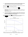
A final open loop Bode plot of your complete system like the one seen in
Figure 3 of section 4.
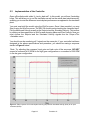
A step response to your system including the actual and simulated velocities
as well as the input command. This should look similar to the Figure 4 of
section 5.
V.
Final remarks and conclusions as well as answers to the post lab questions.
6.1
Post Lab Questions
1)
Were there any design limitations or problems you encountered during the lab? If so,
how were these limitations overcome?
2)
Did the actual response of the system match directly to that of the simulated model?
From your understanding of the system, what could you theorize is the source of
these discrepancies and how would you improve them?
3)
If you were given the same speed control experiment again, would you choose a
lead compensator as a controller or would you use a different approach? Explain.
Page # 10
Revision: 01