1
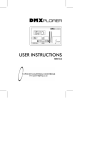
SRV02-Series
Rotary Flexible Link
User Manual
Table of Contents
1.
2.
3.
4.
6.
Description................................................................................................................................3
1.1 Modular Options....................................................................................................................4
System Nomenclature and Components...................................................................................5
System Setup and Assembly.....................................................................................................6
3.1 Typical Connections for the SRV02 – FLEXGAGE Experiment.........................................7
3.2 Calibrating the Strain Gage....................................................................................................7
3.2.1. Offset Adjustment..............................................................................................................8
3.2.2. Gain Adjustment................................................................................................................8
Rotary Flexible Link Module – Range of Experiments & Features.......................................10
System Requirements & Specifications..................................................................................11
6.1 System Specifications..........................................................................................................11
Index of Tables
Table 1 - Rotary Family Modules.......................................................................................................4
Table 2 - Component Names..............................................................................................................5
Table 3 - Typical Connections............................................................................................................7
Table 4 - System Requirements........................................................................................................11
Table 5 - FLEXGAGE Specifications..............................................................................................11
Index of Figures
Figure 1 - FLEXGAGE coupled to SRV02........................................................................................5
Figure 2 - Strain gage close up...........................................................................................................5
Figure 3 - Contents of FLEXGAGE package.....................................................................................6
Figure 4 - Attaching to the SRV02....................................................................................................6
Figure 5 - Place tip in middle slot.......................................................................................................8
Figure 6 - Move tip 4 slots counter clockwise....................................................................................9
Page # 2
Revision: 01
SRV02-Series
FLEXGAGE - Rotary Flexible Link
User Manual
1.
Description
The rotary flexible Link consists of a strain gage which is mounted at the clamped end of
a thin stainless steel flexible link. The output is an analog signal proportional to the
deflection of the link. The system is designed to mount on a Quanser rotary servo plant
resulting in a horizontally rotating flexible link to perform flexible link control experiments.
This system is similar in nature to the control problems encountered in large light space
structures where the weight constraints result in flexible structures that must be controlled
using feedback techniques. A DC motor rotates a flexible link from one end in the
horizontal plane. The motor end of the link is instrumented with a strain gage that can
detect the deflection of the tip. The rotary flexible Link is an ideal experiment intended to
model a flexible Link on a robot or spacecraft. This experiment is also useful in the study
of vibration analysis and resonance.
Page # 3
Revision: 01
1.1 Modular Options
Quanser values itself for the modularity of its experiments. The SRV02 rotary plant
module serves as the base component for the rotary family of experiments. This modular
philosophy facilitates the change from one experimental setup to another with relative
ease of work and a valuable savings in cost. The following table lists the experiments
currently available in the rotary family of products utilizing the SRV02 as the base.
Module Name
Description
Ball & Beam
The Ball & Beam experiment requires the user to manipulate the
position of a rolling ball on a beam.
Flexible Link
The Flexible Link experiment requires the user to command a tip
position of the flexible link attached to the SRV02.
Flexible Joint
A rigid beam is mounted on a flexible joint that rotates via the SRV02
and the user is to command the tip position of this beam.
Gyro/Stable Platform
The purpose is to maintain the line of sight of an instrument mounted
on a rotating platform (SRV02).
Inverted Pendulum
The purpose is to balance the inverted pendulum through a rotary
motion arm (SRV02).
Double Inverted
Pendulum
The double inverted problem adds to the complexity of the single
pendulum by introducing a 2nd pendulum.
2 DOF robot module
This experiment requires the x-y positioning of the “end effector”.
2 DOF Rotary Gantry
This experiment requires the control of the swing of a x-y gantry crane
using a 5 DOF linkage.
2 DOF inverted
pendulum
Balance a pendulum that is free to fall in 2 directions. The pendulum is
attached to the tip of the 2 DOF robot.
Table 1 - Rotary Family Modules
Page # 4
Revision: 01
2.
System Nomenclature and Components
Figure 1 & Figure 2 below depict the FLEXGAGE module. The standard FLEXGAGE is
equipped with a strain gage sensor resulting in an analog signal proportional to the
deflection of the tip. Refer to the following table to associate the components with their
corresponding photographs.
1
SRV02 Base
5
Strain gage circuit
2
FLEXGAGE module
6
Thumbscrews
3
FLEXGAGE Link
7
Sensor connector
4
Strain gage
Table 2 - Component Names
3
2
7
1
Figure 1 - FLEXGAGE coupled to SRV02
5
4
6
Figure 2 - Strain gage close up
Page # 5
Revision: 01
3.
System Setup and Assembly
The rotary flexible Link module requires minimal assembly. Figure 3 Below shows the
components of the FLEXGAGE package you should have received. The FLEXGAGE
package includes the module itself, a calibration stand and the sensor wire *Note the
FLEXGAGE is already pre-calibrated to the correct settings.
Figure 3 - Contents of FLEXGAGE package
The only assembly required is to mount the FLEXGAGE onto the SRV02. Make sure the
SRV02 is configured in the High-Gear configuration. If you are unsure about the SRV02,
please refer to the SRV02 User Guide. Simply place the FLEXGAGE onto the load shaft
(middle shaft) and secure the FLEXGAGE in place by tightening the 2 thumbscrews as
seen in Figure 4 below.
Figure 4 - Attaching to the SRV02
Page # 6
Revision: 01
3.1 Typical Connections for the SRV02 – FLEXGAGE Experiment
The following table describes the typical setup using the complete Quanser solution. It is
assumed that the FLEXGAGE is being used along with an SRV02, UPM and Q8 DAQ
board.
From...
FLEXGAGE
Strain Gage
(Component 4)
To...
S2 Connector
on UPM.
Cable
Description
6-pin mini
This cable results in delivering a ±12V bias
DIN to 6-pin to the potentiometer and measuring the
mini DIN.
potentiometer signal voltage on S2 of the
UPM.
Encoder 0
*This is the load gear connector on
position measurement the terminal
board.
5-pin Stereo The terminal board should supply the
DIN to 5-pin encoder with the +5V and ground. The load
Stereo DIN. shaft position signal will then be measure on
Encoder channel 0.
'To Load'
Connector on
UPM.
Motor on
SRV02.
6-pin DIN to This connects the output of the amplifier to
4-pin DIN.
the motor. You can use a variety of cables
resulting in a different gain from input to
output. The cables available are Gain=1,
Gain=3, Gain=5.
Analog Signals
(To A/D)
Analog input
channels 0-3
on the DAQ.
5-pin DIN to From the UPM, connect all the analog
4x RCA.
sensor signals to the terminal board such
that S1 is measured on analog input 0. S2 AI # 1, S3 - AI # 2, S4 - AI # 3.
Analog output
channel 0 on the
DAQ.
UPM input
(From D/A)
RCA to 5-pin This is the command output from the DAQ
DIN.
that will be amplified and drive the motor.
SRV02 Encoder
Table 3 - Typical Connections
3.2 Calibrating the Strain Gage
The FLEXGAGE uses a strain gage mounted at the base of the link to measure the
deflection of the tip of the link. Before the module is shipped, the unit would have been
fully calibrated to the correct specifications. The following section will describe the
calibration routine in order to ensure the unit maintains its correct calibration and thus
remains operating correctly.
This section describes functional tests to determine if your FLEXGAGE sensors are
operating normally. It does not cover any performance tests. All these tests require an
understanding of Simulink (or Labview), WinCon (or equivalent), and Q8 (or equivalent
data acquisition board you are using). You should be able to “build” a controller that can
measure and apply desired signals.
Page # 7
Revision: 01
In the following sections, it is also assumed that the FLEXGAGE is connected as
described in the Typical Connections table above.
As you can see in Figure 4 above, the FLEXGAGE circuit has 2 adjustable
potentiometers. One is for the Offset adjustment and the other is for the Gain
adjustment. Build a controller that displays the measurement from analog input # 1 (This
is the signal connected to S2 on the UPM).
3.2.1. Offset Adjustment
Mount the FLEXGAGE onto the calibration stand that shipped with the module. Place the
tip in the middle tooth of the comb as seen in Figure 5 below.
Figure 5 - Place tip in middle slot
Your controller should be running and reading 0 Volts. If there is an offset in your
measurement, adjust the Offset potentiometer such that your measurement reads 0
volts.
3.2.2. Gain Adjustment
After adjusting the measurement to its 0 measurement, you should check and make sure
the sensor is calibrated as desired. The sensor should read 1 Volt per 1 inch of tip
deflection. Each slot or tooth in the calibration comb corresponds to ¼ inch displacement.
Move the tip counter-clockwise 4 slots as seen in Figure 6 below.
Page # 8
Revision: 01
Figure 6 - Move tip 4 slots counter clockwise
Your measurement should now be reading 1 volt. If you do not read 1 volt, gently adjust
the Gain potentiometer such that you are reading 1 volt.
*It is strongly urged to NOT adjust the gain potentiometer too much as the system should
have already been calibrated and should not have drifted a significant amount.
Once you are reading 1 volt, move the tip 8 slots clockwise (4 slots away from 0) and
check that you are now reading -1 volts.
After ensuring that your sensor is generating 1 volt / 1 inch deflection, you return the tip to
its equilibrium (0) postion and make sure it is again reading 0 volts. If not, adjust the offset
potentiometer once again to read 0 volts.
*As mentioned above, the unit is already calibrated before shipping and any adjustment
would only be minor if any. This calibration routine is only provided for extreme
circumstances.
For technical support referring to any of the FLEXGAGE components, please visit us on
the web at: www.Quanser.com.
Under our Technical Support section, please fill out a technical support form indicating
your problem in detail and one of our engineers will be happy to respond to your request.
Page # 9
Revision: 01
4.
Rotary Flexible Link Module – Range of Experiments & Features
The rotary flexible Link is an ideal experiment intended to model a flexible Link on a robot
or spacecraft. This experiment is also useful in the study of vibration analysis and
resonance. The model is designed to accentuate the effects of flexible links in robot
control systems. Such flexibility is common in lightweight robots designed for space
applications. The students will be exposed to control the vibrations in the link as well as
dealing with higher modes of vibration.
FLEXGAGE Key Features:
•
•
•
•
•
•
•
High Quality Aluminum chassis with precision crafted parts
High Resolution Strain Gage to sense link deflection
Fully documented system models & parameters
Fast and Easy attachment to the SRV02 plant
Open Architecture Facilitates Matlab/Simulink Design
Modular Design
Optional High Precision Light Sensor
Curriculum Topics:
•
•
•
•
•
•
•
•
•
System Modeling & Simulation
Real-Time Control
Full-State Feedback
Frequency Analysis
Vibration & Resonance
Hardware in the Loop
Robotics
Observer Design
Nonlinear Control
Page # 10
Revision: 01
6.
System Requirements & Specifications
The Rotary Flexible Link Module (FLEXGAGE) is designed as an attachment to the
SRV02 plant. Along with the SRV02 plant, the following components are required to
complete the experimental setup.
Component
Quanser Recommended
(Common Configuration)
Power Module
Quanser UPM 1503/2405
Data Acquisition Quanser Q8
Alternative
Other Power Supply that can deliver the
required power.
dSPACE DS 1104 National Instruments
E-Series DAQs
Any other DAQ with at least one A/D,
one D/A and one Encoder input.
Quanser WinCon / SLX / WebLab The Mathworks – RTWT, xPC
Control Software
dSPACE – ControlDesk
National Instruments – Labview RT
Table 4 - System Requirements
6.1 System Specifications
Specification
Value
Units
Module Dimensions
48 x 2
cm2
Flexible Link Length
30
cm
Strain Gage Bias Power
±12
Volts
Strain Gage Measurement Range
±5
Volts
Strain Gage Calibration Gain
1
Volts/Inch
Flexible Link mass
0.065
kg
Flexible Link rigid body inertia
0.005
kgm2
Equivalent Link Stiffness
0.5
Nm/rad
Fundamental Natural Frequency
3.2
Hz
Table 5 - FLEXGAGE Specifications
Page # 11
Revision: 01