1
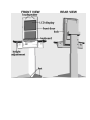
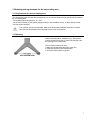
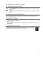
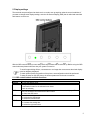
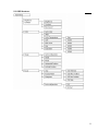
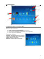
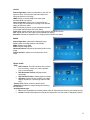
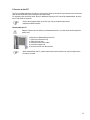
FRONT VIEW
REAR VIEW
1. Introduction...............................................................................................4
1.1. Description of the product ........................................................................... 4
1.2. On the structure and content of this manual ............................................. 4
2. Important information ..............................................................................5
2.1. Warnings, safety measures and ergonomics............................................. 5
2.2. Information on care and upkeep ................................................................. 6
2.3. Transportation............................................................................................... 6
3. Mounting and requirements for the surrounding area ..........................7
3.1. Requirements for the surrounding area ..................................................... 7
3.2. Mounting........................................................................................................ 7
4. Connecting the unit and placing it in service ........................................8
4.1. Connecting terminal to the power supply .................................................. 8
4.2. Connecting to the network and ISDN / modem .......................................... 8
4.3. Placing the PC in operation ......................................................................... 8
4.4. Height adjustment of the terminal............................................................... 8
5. Display settings ........................................................................................9
5.1. OSD control buttons and their functions ................................................... 9
5.2. OSD Structure: ............................................................................................ 11
5.3. Window Structure: ...................................................................................... 12
5.4. Detailed description of the On-Screen-Menu ........................................... 12
6. Access to the PC ....................................................................................14
7. Variants and accessories.......................................................................15
8. Troubleshooting .....................................................................................15
9. Technical specifications ........................................................................16
10. Warranty ................................................................................................18
11. Declaration of conformity ....................................................................20
3
1. Introduction
1.1. Description of the product
The friendlyway butler is an interactive communication terminal for use in enclosed areas. Along with a basic
model many variants for special application purposes are available, as well as comprehensive accessories.
Please read this manual carefully before placing your terminal in service to avoid improper operation. Be
especially sure to read chapter ”Warnings, safety measures and ergonomics”. This will help you to prevent
possible damage to the unit and injury to persons due to improper handling.
Subject to technical changes.
1.2. On the structure and content of this manual
The subject-matter of this manual is the friendlyway butler in its basic model equipped with a multimedia PC
and LCD display. If you need some information to special facilities of separate device variants or to other
accessories, please refer to respective documentation. This document describes how to set up and start up
your terminal, what settings are available on the monitor, and how to conduct routine maintenance. Chapter
“Access to the PC” is meant for computer specialists or at least experienced users, who want to level the new
software or to upgrade a PC. For operation and maintenance of the butler van terminal no specific knowledge
(computing, electronics, etc) is required. Otherwise, it is explicitly indicated in the manual.
Danger of electric shock. Before you disassemble
the PC, turn the terminal off and pull the power cord.
Warning
intended to prevent injury to
persons or damage to
property
Service and upgrade tasks on the PC may only be
performed by trained, professional staff members
Useful information
Connect the device to the power supply with the
power connection cord (included with delivery). The
device is ready for operation.
Individual instruction
1. Open the lock with the enclosed key.
2. Open the front door.
3. Press the Start button on the PC. The system is
preinstalled and the device is started with the
ordered accessory units.
Step-by-step instructions
4
2. Important information
2.1. Warnings, safety measures and ergonomics
When setting up the unit and before placing it in service, please make note of the information in
chapter ”Mounting and requirements for the surrounding area”.
• Transport the unit only in its original packaging or in a suitable packaging that ensures it is
protected against bumps and impact.
• If the unit is brought from a cold environment into the room where it will be operated,
condensation may occur. Wait until the unit has reached the temperature of the room and is
completely dry before putting it in operation.
• Make sure that the local power supply does not exceed or fall short of the nominal voltage range.
Check the adjusted nominal voltage of the unit (see ”Connecting terminal to the power supply” and
see the identification plate).
• A safety-tested power line in compliance with the requirements of the country where it is being
used is required for this device. The device can only be connected to a grounded protected
contact socket.
• Make sure that the socket of the device or the protected contact socket of the facility installation
is freely accessible.
• Lay the lines so that they do not create any hazards (danger of tripping) and so that they cannot
be damaged. Read chapter ”Connecting the unit and placing it in service” of these operating
instruction on connecting the device.
• Repairs on the device may only be performed by authorized specialists. Unauthorized opening or
improper repairs may result in considerable hazard for the user (electric shock, danger of fire).
• Proper operation of the device, (as per IEC 950/EN60950) is only ensured if the housing is fully
assembled and the rear side covers for installation locations are in place (electric shock, cooling,
fire protection, radio interference)
• Before opening the device, the device must be disconnected from the power supply by removing
the power plug. Follow the instructions and information in these operating instructions if you open
the device.
• Install only system add-ons that comply with the requirements and specifications for safety,
electro-magnetic compatibility and telecommunications terminal device equipment. Installing other
add-ons may violate these requirements and specifications or may damage the system. You can
obtain information about which system add-ons are permissible for installation from your sales
center or from our service department.
• If you install or replace system add-ons that cause defects to the device, the warranty is voided.
• The weight of the device is ca. 60 kg, depending on the configuration.
• To obtain sufficient stability it is required that the terminal is screwed to the floor with mounting
bolts on special openings in the bottom plate.
• If the unit keeps displaying the same pattern for a long period of time the image may be „stuck”
to the screen. To avoid image sticking it is recommended to use alternating or animated images or
a screensaver. Please see also the display manufacturer's directions.
• Keep this information on hand along with all of the documentation together with the unit. If you
transfer the unit to a third party, please transfer all of the documentation along with it.
• Data lines to peripheral devices must be equipped with adequate shielding.
• If your device is equipped with a DVD-ROM drive, the following applies:
The DVD-ROM drive contains a light-emitting diode (LED), classification in accordance with IEC
825-1:1993:LASER CLASS 1.
• You will find additional safety information in the respective manuals for PC and other accessories
or installation devices (if ordered in addition).
5
2.2. Information on care and upkeep
Housing
• ALUMINIUM VERSION: Do not clean with sharp objects, for example, metal sponge or similar cleaning
objects! Clean only with a damp cloth and gentle cleaning agents. Do not directly spray cleanser onto the
unit.
Be careful with such optional devices as loudspeaker, camera and card reader.
Screen
• Clean with standard window cleansers. To prevent exposure to moisture, do not directly spray cleanser onto
the device. Instead of this, wipe off the screen with a moist cloth.
Keyboard
• Protect from dirt.
2.3. Transportation
Transport your friendlyway butler in the original package only or in one of the optionally available shipping
crates.
6
3. Mounting and requirements for the surrounding area
3.1. Requirements for the surrounding area
Your friendlyway butler was specially developed for use in enclosed areas and has specific requirements for
the surrounding area:
• Permissible ambient temperature: 15 - 30°C
• No sources of warmth or heat (direct sunlight, heater) in the immediate vicinity, no direct effects of heat.
• No high relative humidity
The machine must only be operated under the environmental conditions listed above. Please
take this into consideration when selecting a place to set up the device.
3.2. Mounting
To prevent the terminal breakdown due to external
impact (counterpressure, vandalism, etc.), the terminal
must be screwed to the floor. In each foot plate there are
two openings for mounting bolts.
To mount the terminal to the floor:
1. Make the corresponding drill holes in the floor.
2. Install the terminal on the desired place.
3. Screw the bottom plates to the floor.
7
4. Connecting the unit and placing it in service
4.1. Connecting terminal to the power supply
You should only operate the device from a grounded alternating current socket for a 220-240 V /
50 Hz power supply
Connection:
Connect the device to the power supply with the power connection cord. The device is ready for
operation.
4.2. Connecting to the network and ISDN / modem
The network and ISDN / modem connection requires a trained staff that is also capable of making the
required communication settings.
4.3. Placing the PC in operation
1. Open the lock with the enclosed key.
2. Open the front door.
3. Press the Start button on the PC. The system is preinstalled and the device is started with the ordered
accessory units.
4. Close the terminal.
4.4. Height adjustment of the terminal
The friendlyway butler provides the possibility to adjust it by height. It can be done with the
control buttons. The total height can vary from 148 cm to 198 cm.
8
5. Display settings
The terminals are preconfigured so that there is no need to set up anything under the normal conditions. If
you want to change some display settings, enter the On-Screen-Display (OSD) that is called and controlled
with buttons on the cover.
With the OSD control buttons you can easily reach any functions that must be set up. Before using the OSD
control elements please make sure that your system is turned on.
To avoid image sticking effects, a screensaver or an image that moves across the whole display
must be obligatory displayed!
To reach optimal quality and position of the picture, autoconfiguration should be performed.
To ease the setup on the OSD menu, the timeout parameter can be set to maximum.
5.1. OSD control buttons and their functions
Key
POWER
MENU
EXIT
LEFT
RIGHT
Function
- to turn the display on/off
- to open the main menu
- confirmation button for the selected menu items
- back to submenu
- to switch to the Exit icon when the OSD main menu or a submenu is displayed. The
Exit icon should be confirmed with the Menu button.
- to leave the OSD menu
- to activate the brightness menu
- to minimize the settings bar
- to select the left menu item
- to activate the contrast menu
- to increase the settings bar
- to select the right menu item
9
Working with the menu system
1. With the OSD off, push the Menu button to activate the main OSD menu.
2. Use the Left and Right buttons to move through the main menu. To select a desired submenu,
press the Menu button after your selection. The selection tabs are also highlighted and explained via
onscreen text in the upper right of the OSD screen.
3. After selecting a submenu, use the Left or Right buttons to move through the submenu. To select
a setting icon, press the Menu button after your selection. The selection tabs are also highlighted
and explained via onscreen text in the upper right of the OSD screen.
4. There are two types of icons: Some have a single function and must be confirmed with the Menu
button, the other option are setting bars. Once a setting bar appears, it can be increased or
decreased via the Left and Right buttons. The setting bar moves and the numeric value indicator
changes to reflect your adjustments.
5. There are several ways to close the OSD menu:
- Waiting some seconds (timeout).
This time can be adjusted as needed in one of the menus.
- In the main menu or in submenu, press the Exit button. This highlights the Exit icon in the menu.
Then press the Menu button to leave the OSD menu.
- After an Autoadjust and confirmation the OSD menu closes automatically.
- After adjusting a setting, press the Menu button to go back to the submenu, then press the Exit
button or use the Right button to select the Exit icon, then confirm the selection with the Menu
button.
10
5.2. OSD Structure:
11
5.3. Window Structure:
5.4. Detailed description of the On-Screen-Menu
Adjusted menu items will be saved if:
•
•
•
•
the OSD is closed by selecting and confirming the Exit Menu icon
the sleep mode is toggled with the Power Key
the green smiley is selected after Autoconfiguration in Color or Image menu
the color value is reset to sRGB default
BRIGHTNESS–CONTRAST
Brightness: Adjusts the display brightness. If supported,
brightness will be regulated using the connected inverter.
Contrast: Adjusts the image contrast.
Black Level: Adjusts the black level of the image.
12
COLOR
Autoconfiguration: performs a calibration of the ADC for
optimum colors. For best result, black and white level
should be present in the image.
sRGB: Return to default sRGB color values (also
activates sRGB color space).
Color Temperature: Allows you to choose different
values for the color temperature including a user defined
setting in RGB color space.
CMY: Modify the proportion of cyan, magenta and yellow
in the image (also activates CMY color space).
Flesh Tone: Adjusts the flesh tone of the image (requires sRGB color space).
Hue: Adjusts the hue of the image (requires sRGB color space).
Saturation: Adjusts the saturation of the image (requires sRGB color space).
IMAGE
Autoconfiguration: optimizes the displayed image.
Adjusts phase and image position automatically.
Width: Adjusts image width.
Phase: Adjusts image phase.
Horizontal position: Adjusts the horizontal position of the
image.
Vertical position: Adjusts the vertical position of the
image.
TOOLS & OSD
- OSD
• OSD Timeout: The OSD vanishes after a certain
time of inactivity. Values of 2-16s are possible
(16s is recommended).
• OSD Horizontal Position: Adjusts position
horizontally.
• OSD Vertical Position: Adjusts position vertically.
• OSD Size: Doubles the size of OSD (only valid if
display resolution is 2 times larger than the OSD
size)
- Factory reset: Return to factory default values
- Sharpness: Modifies the image filtering with shrinking
and expansion
- Autoadjustment type:
• Fast: Quick autoadjustment method (coarse adjust for fast resolution switching, like during bootup).
• Normal: Standard autoadjustment method (fine adjustment once the system is displayed properly)
13
6. Access to the PC
The PC is located behind the front door of the terminal. Open the front door to get access to the drives and
Start and Reset buttons (after loosing the top tension belt).
For equipping with extension cards, drives or additional memory the PC should be disassembled, at which
the PC cap must be removed.
Service and upgrade tasks on the PC may only be performed by trained,
professional staff members
Disassemble the PC
Danger of electric shock. Before you disassemble the PC, turn the terminal off and pull the
power cord.
Instruction on disassembling of the PC:
1. Open the lock with the key.
2. Open the front door.
3. Extract the connection cable.
4. Loose the tension belt.
5. Remove the PC from the terminal.
When reassembling the PC, please make sure that the tension belt does not slip and the
front door is closed.
14
7. Variants and accessories
Your friendlyway butler terminal is offered as a basic model and in several variants. These variants differ in
basic configuration of hardware and software aimed at specific application purpose. Additionally you can
obtain extra accessories and combine within the constructional possibilities. Configuration of the device is
performed at the factory after the order, and no later terminal upgrade can be performed as a rule. If you
have questions regarding the operation and maintenance of optional devices as well as special accessories,
please refer to the respective manuals. You can acquire it in the attached list of Variants and accessories.
8. Troubleshooting
An up-to-date and comprehensive database of potential problems and their solutions can be found at our
home page at the following website: www.customers.friendlyway.com.
Certain hints on troubleshooting and problem solving are also available in the corresponding manuals for
components and accessories.
15
9. Technical specifications
Dimensions:
1980/1480 x 47 x 30 mm (H x W x D)
Weight:
60 kg, depending on the configuration
Housing:
Anodized aluminum
Ambient temperature:
permissible in the range 15 °C - 30 °C
Standard equipment:
17“ LCD display, 2 built-in loudspeakers
PC Fujitsu Siemens Esprimo C (Pentium 4 3,2 GHz, 512 MB RAM, 160 GB hard
drive, DVD-ROM, serial port, USB, Ethernet port, Windows XP Professional)
FRONT VIEW
SIDE VIEW
16
TOP VIEW
Subject to technical changes, enhancements and errors. The weight and dimensions given are approximate
values.
17
10. Warranty
We offer a guarantee on all systems for a period of 12 months. During this time, friendlyway customer
support is available to you daily from 9 a.m. till 5 p.m. We will be happy to assist you with any questions and
problems.
You can reach us on our hotline at 1-800 374 36 35 (only in Germany) or at +49 (0) 89 / 95 97 91-500 or by
e-mail at [email protected].
We offer telephone support for troubleshooting and error correction. Repairs take place in our facility. If you
require on-site assistance, travel costs will be billed according to the distance involved.
18
NOTES
19
11. Declaration of conformity
CE
Declaration regarding conformity
This declaration applies to the products designated below:
Product: Terminal
Device type: Multimedia, representational Internet terminal
Model: butler
This is to confirm that the products comply with the essential protection requirements stipulated in the
regulations of the Council for adjustment of legal requirements of member states regarding electro-magnetic
compatibility (89/336/EEC) as modified by 91/263/EEC, 92/31/EEC, 93/68/EEC as well as 93/97/EEC and the
low voltage regulation 73/23/EEC as modified by 93/68/EEC.
This declaration is submitted by
friendlyway AG
Feringastr. 9
85774 München-Unterföhring
The relevant tests were performed at accredited testing laboratories.
The following standards were used to evaluate the products in terms of electro-magnetic compatibility and in
terms of the low-voltage regulation.
EN 55 022: April 1998
EN 50 082-2: February 1996
( EN 61000-4-2:1995 +A1:1998 / EN 61000-4-3:1996 +A1:1998 / ENV 50204:1995 /
EN 61000-4-4:1995 / EN 61000-4-5:1995 / EN 61000-4-6:1996 / EN 61000-4-11:1994 )
EN 60950:1992 / +A1:1993 / +A2:1993 / +A3:1995 / +A4:1997 / +A11:1997
Munich, 21 August 2000
Legally binding signature
of the distributor
20