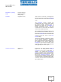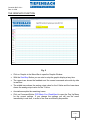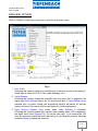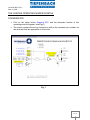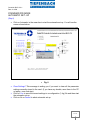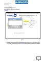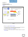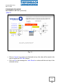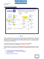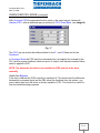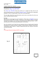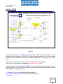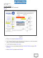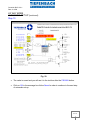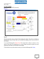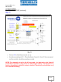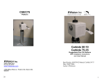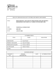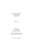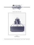
1
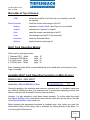
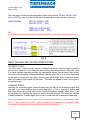
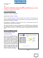
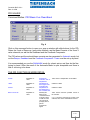
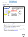
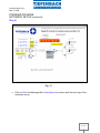
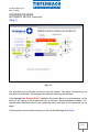
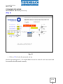
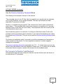
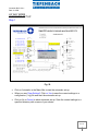
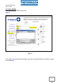
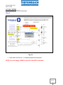
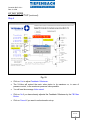
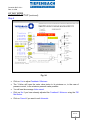
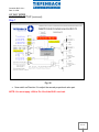
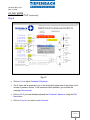
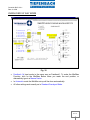
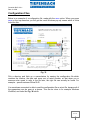
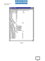
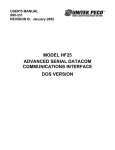
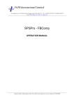
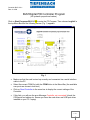
Controller BLS1 V 4.x Date 11-2009 BLS1Digital PID Controller Program (for hydraulic proportional valves) Click on Start Programs BLS1 V3.6 to enter the PC-Program. Then choose 'english' in the top Menu-Bar and the following screen (Fig. 1) appears: Fig. 1 Make sure that the card is wired up correctly and connected via a serial interface cable to the PC. Select the correct COM-Port with the COM Button in the Menu-Bar, (the available com ports are shown in bold text) Click on Read Controller in the menu bar to display the current settings of the Controller. If this fails, you will see the error Message Controller not connected! (check the COM ports and cables etc. Ensure you have the card driver and USB port driver installed on your PC / laptop) 1 / 38 Controller BLS1 V 4.x Date 11-2009 Menu-Bar at Top of Screen: COM: Read Controller: shows the possible Com-Ports, the one currently in use will be checked loads the current card settings to the PC Graphic: switches to Graphic Mode, (see Page x for more detail) „english‟: switches from 'german' to „english‟ Save: saves the current card settings to the PC Load: load settings from the PC to the controller Automatic: starts the Automatic Mode Options-: special functions (see page 8) BLS1 Card Operating Modes: There are four operating modes: 1. Standard PID1 Mode 2. Overlayed PID2 Mode 3. 4/3 Way Valve Mode 4. 3/3 Way Valve Mode page page page page 10 19 22 36 Each operating mode will be covered individually and in detail later in this manual. (from Page x onwards) Available BLS1 Card Operating Functions on Main Screen: MANUAL MAX. / MIN. INPUT check box: Manual Min/Max Value Generally speaking, the maximum and minimum command and / or feedback values are set either by shifting the valve to its maximum and to its minimum operating position (see below) or by using the Automatic Function (see also below). However, it is also possible to input these values manually. To do this select the check box Manual Min/Max Value (see above) then enter the value into the text box to the right of the Manual Min/Max Value check box. Before pressing the appropriate command or feedback max. /min. button you must first decide which units you are using, volts or miliamps, by clicking directly on the letter V or mA to the right of this text box. 2 / 38 Controller BLS1 V 4.x Date 11-2009 The next step is to click on the appropriate, yellow option button, FB Max, FB Min, CMD Max or CMD Min, etc. Only then is the value accepted by the card (see also following). option buttons: FB-Val. 4-20mA (6d) FB-Val. 0-10V (6b) CMD-Val. 4-20mA (6d) CMD-Val. 0-10V (6b) NB: the relevant card rack pin number is written in brackets, to the right of the option button. Fig. 2 INPUTTING MAX MIN VALUES FROM SYSTEM FEEDBACK SIGNAL It is more usual to input the max. and min. feedback values by using the valve‟s hydraulic pilot circuit to position it to its maximum and minimum operating positions. When the valve is at each extreme operating position the appropriate square yellow button (see above) should then be depressed, having beforehand selected either Ma or V as units, depending on the type of sensor you are using. Pressing the yellow radio button loads the current value of feedback input signal into the card. The value will appear in blue to the right of the yellow button. COMMAND SIGNAL Inputting the command signal values requires that you call up the maximum signal that you plan to use from whatever this is being supplied (e.g. PLC or joystick or similar) and then press the square yellow radio button, having beforehand selected either Ma or V as an operating unit. Inputting the minimum value is a similar process. The automatic method is described below. It varies slightly from mode to mode and will be described separately. Note: The transducer / sensor must be in the appropriate position for the feedback value and / or the joystick or the PLC must be supplying the appropriate command value (Automatic mode guides you through this procedure - see below.) 3 / 38 Controller BLS1 V 4.x Date 11-2009 Note: The difference between Min and Max Value MUST be greater than 5 V or 10 mA. Otherwise the controller will not accept the values and resets to a Minimum Value of 0 and to a Maximum Value of 9.99V or 19.99mA. FUNCTION GENERATOR check box: Function-Generator option button: Square, Triangle Click on the square check box to start the internal Function-Generator. This generates an internal command signal analog input and the waveform can be selected using one of the two check circles Square or Triangle. The frequency is adjustable in several steps from 0.52 to 8.38 seconds using the UP DOWN buttons to the right of the check box. The Function-Generator is useful for manual set-up of the PID Rates and for fine-tuning. The amplitude is 50% (this is not adjustable) of the full scale and is placed symmetrically about the middle of scale (5V or 10mA), which means it runs between 25% and 75% of full scale. DIGITAL COMMAND VALUES Command Button: Digital Command-Values Click on this command button to open a pop up window with 7 slide buttons, which allow you to preset up to 7 different Command-Values. These digital command values are activated on the card via 3 digital inputs (12d, 12b, 10d), using binary code. If all three are in low state (or are simply not connected), the card defaults to the current analog input (for more detailed information on the binary pin settings see page 14 in the BLS1 controller user manual). Fig. 3 4 / 38 Controller BLS1 V 4.x Date 11-2009 PID VALUES Command Button: PID1/Basic-Curr./Dead-Band Fig. 4 Click on this command button to open up a pop up window with slide buttons for the PIDRates, the 2 sets of Ramp-up / ramp down features, and the Base-Currents of the X and Y valve solenoids, as well as the Deadband and the Feedback-Comparator. The PID values and the solenoid base currents are also generated in Automatic mode, but not the Ramps, Deadband and the Feedback-Comparator. These must be set-up by hand. It is recommended you use the Automatic mode for a basic set-up and then do the finetuning by hand. Often the result of the Automatic-Mode is quite acceptable and there is little or no tuning to be done. THE PID FUNCTION IN MORE DETAIL P-Rate: Adjustable 0100% I-Rate: Adjustable 0100% D-Rate: Adjustable 0100% Base Current X/Y: Adjustable 0100% Proportional Controller Gain or Amplification Amplification of the Integral of the Controller-Diff. Amplification of the Differential of the Controller-Diff. basically this takes up the „mechanical slack in the pilot valve, so that the valve can react more promptly when it gets its proportional signal. 100% means a multiplication of 20 TIMES. related to P-Rate. related to P-Rate 100% means maximum possible current of the solenoid. e. g. If 1.5A is the maximum DC current of the solenoid, 50% means 750mA Basic-Current. 5 / 38 Controller BLS1 V 4.x Date 11-2009 Ramp Down / (2.Ramp Down) Same as Ramp Up applies to direction down (10-0V). Deadband: Adjustable 0-100% 100% means ¼ of full scale, for example 10V means a max. of 2.5 V providing a Deadband of 1.25 V either side of the current command value. The Deadband function converts the command value into a zone or band, where the actual incoming command value is situated at the centre and the Deadband is located symmetrically around it. So the controller will not work unless the feedback value moves outside of this zone. The controller then resumes its function until the command and the feedback value are at the same level. At that point the controller will restart the Deadband function and the valve solenoid currents will return to their Base Current setting. This function effectively increases the lifetime of the solenoid, especially in applications where a slight offset does not negatively affect the operation of the system. Setting the Deadband to zero forces the controller to work continually, which is hard on the solenoids and is generally hard on the system. Feedback Comparator: Adjustable 0100% Function: If the actual feedback value is higher than the setting of the Feedback Comparator in the card, a digital signal is applied to pin number 16b (Dig.Out1/FBComp). For example, if the current minimum feedback value is 5V and its maximum is 10V, then a 50% Feedback Comparator setting would mean that a feedback value higher than 7.5V would switch on the digital output at 16b; conversely, one lower than 7.5V would switch off the digital output. 6 / 38 Controller BLS1 V 4.x Date 11-2009 THE GRAPHICS FUNCTION Fig. 5 Click on Graphic in the Menu-Bar to open the Graphic-Window. With the Start/Stop Button you can start or stop the graphic display at any time. The upper trace shows the feedback and the current command value side-by-side in real time. The middle trace shows the analog output value for the X-Valve and the lower trace shows the analog-output value for the Y-Valve. Annotations explain the remaining traces. Click on Command Button PID1/Basic-Curr./Dead-Band to open the Pop Up Menu for the current settings .If you change the settings you will see the result immediately in real time, in order to fine-tune as efficiently as possible. 7 / 38 Controller BLS1 V 4.x Date 11-2009 MENU BAR OPTIONS Click on “Options" in the upper menu bar to open the drop-down menu: Fig. 6 1. Error 4 mA: Checking this function makes the controller stop if the input-current of an analog 420mA input is below 4 mA (PLC fault, cable breakage, etc.) 2. Valve Release: Checking this function means the controller runs only when +24V is applied to the digital input Valve-Release (this is pin 12z on the card rack). If Valve Release is not checked then, on power outage, the proportional valve(s) will switch off and the system will stop at its current position (see below for further explanation). 3. Open Without Release (only works when Valve Release is checked): Checking this function means the controller runs normally when +24V is applied to the digital input Valve-Release (Pin 12z on the card rack). If you remove the 24V from this input the proportional valve pair will go to its maximum position, following whatever Ramp Up speed has been set. 8 / 38 Controller BLS1 V 4.x Date 11-2009 4. Close Without Release (only works when Valve Release is checked): Checking this function means the controller runs normally when +24V is applied to the digital input Valve-Release (Pin 12z on the card rack). If you remove the 24V from this input the proportional valve pair will go to its minimum position, following whatever Ramp Down speed has been set. 5. CMD Value invert, FB1 Value invert, FB2 Value invert The selected analog input is inverted 6. 2nd PID ST+4/3. In Standard and in 4/3 Way Mode the PID2 setting is used for a falling command signal (negative ramp) while PID1 setting is used for a rising command value (positive ramp). This feature is useful when the hydraulic system behaves quite differently between rising up and falling ramps. 7. Error deviation If the controller is not able to reach its target position (i.e. if the feedback signal cannot be matched to the command signal) within 1.5 sec. it will switch off. Resetting this error requires that both command and feedback value first be taken to zero. 8. Extended Ramps If you select this you will extend the maximum ramp time to 15 seconds in steps of 100 millisecs. 9. Overlayed 3/3 Way This function is only available when Overlayed Mode (see Fig. 6) is selected. The principle of operation is explained in the following paragraph. This mode utilises the same outputs as for the directional solenoids 1 and 2 in Standard Overlayed Mode (there are no directional solenoids in the 3/3 Way Mode so these outputs can be re-allocated) to power a second pair of proportional pilot valves. One proportional valve pair operates an inlet proportional valve; the other pair operates an outlet proportional valve. The second proportional main valve also requires a second feedback input, for its valve piston position indicator, which is called Feedback1b. The option of two such inputs is given, one for a 0-10V feedback signal and one for a 4-20mA feedback signal. Note: If you check the option inverse FB1, you will also invert signal FB1b. 9 / 38 Controller BLS1 V 4.x Date 11-2009 THE VARIOUS OPERATING MODES IN DETAIL STANDARD PID Click on the option button Standard PID1 and the schematic function of this operating mode will appear. (see Fig. 7) The screen contains the set-up functions as well as the connector pin numbers on the card rack that are appropriate to this mode. Fig. 7 10 / 38 Controller BLS1 V 4.x Date 11-2009 STANDARD PID MODE AUTOMATIC SET- UP (Step1) Click on Automatic in the menu bar to start the automatic set-up. You will see the screen shown below. Fig. 8 Clear Settings? This message is asking you if you want to clear all the parameter settings currently stored in the card. (if you have any doubts, save them to the PC or laptop – see next step). Click on Yes to save the current settings to a configuration (*.cfg) file and then start the automatic set-up. Click on No or Cancel to abort automatic set-up. 11 / 38 Controller BLS1 V 4.x Date 11-2009 STANDARD PID MODE AUTOMATIC SET-UP (continued) (Step2) Fig. 9 Save the current settings to a specified directory with a name of your choice (if you Cancel this procedure you will run Automatic set-up without saving the old settings) 12 / 38 Controller BLS1 V 4.x Date 11-2009 STANDARD PID MODE AUTOMATIC SET-UP (continued) (Step 3) Fig. 10 Click on Yes to adjust Feedback 1 Maximum. The X-Valve will be sent to the physically highest point of travel of the valve piston, or in the case of pressure control to the maximum value possible. You will see the message Value Saved (Fig. 11). Click on No if you have already adjusted the Feedback1 Maximum by using the FB1 Max button. 13 / 38 Controller BLS1 V 4.x Date 11-2009 STANDARD PID MODE AUTOMATIC SET-UP (continued) (Step 4) Fig. 11 Click on Cancel if you want to exit Automatic set-up. (the value will be saved to the text box behind the FB1 MAX button.) Click on OK in the message box Value Saved to continue with the next step of the automatic set-up. 14 / 38 Controller BLS1 V 4.x Date 11-2009 STANDARD PID MODE AUTOMATIC SET-UP (continued) (Step 5) Fig. 12 Click on Yes to adjust Feedback1 Minimum. The X-Valve will be sent to the physically highest point of travel of the valve piston, or in the case of pressure control to the maximum value possible. You will see the message Value Saved. (Fig. 13). Click on No if you have already adjusted the Feedback1 Maximum by using the FB1 Min button. Click on Cancel if you want to exit Automatic set-up (the value will be saved and you will see it in the text box behind the FB1 MIN Button). 15 / 38 Controller BLS1 V 4.x Date 11-2009 STANDARD PID MODE AUTOMATIC SET-UP (continued) Step 6) Fig. 13 Click on OK in the Message-Box Value Saved to continue with the next step of the automatic set-up. 16 / 38 Controller BLS1 V 4.x Date 11-2009 STANDARD PID MODE AUTOMATIC SET-UP (continued) (Step 7) Fig. 14 The automatic set-up will now proceed to test the system. The piston rod should go up and down several times. The progress bar indicates how long this will take. If the Message-Box System Error!!! appears, this means there is no pilot pressure, or the wiring of the valves or the transducers etc. is incorrect. Recommended procedure is to operate each individual valve in the system by hand, and then try the automatic set-up again. If the automatic set-up works correctly you will see the Message-Box Ready. 17 / 38 Controller BLS1 V 4.x Date 11-2009 STANDARD PID MODE AUTOMATIC SET-UP (continued) (Step 8) Fig. 15 Click on OK to finish the automatic set-up. Now the new settings for P, I, D and the Basic Current for valves X and Y are saved and the controller should operate correctly. 18 / 38 Controller BLS1 V 4.x Date 11-2009 OVERLAYED PID 2 MODE Fig. 16 Click on the option button Overlayed PID2 (see Page 9 and also Fig. 6) and a schematic representation of this operating mode will appear. (Fig. 16, above). The screen window contains all of the appropriate functions as well as the card rack pin numbers appropriate for the proper use of this mode. Click on Read Controller in the menu bar to see the current card settings. If this fails you will see an error Message Controller Not Connected! Using of this mode is the same as with Standard PID1, but with the addition of a second PID2 controller as a separate function, making a few additional settings necessary. These are: 1. 2. 3. 4. Feedback 2 functions exactly as Feedback 1. Command Button PID 2 / Deadband. (see Fig. 16) check box Bypass Slider Delay Time SW1/SW2 19 / 38 Controller BLS1 V 4.x Date 11-2009 OVERLAYED PID 2 MODE (continued) With Overlayed PID2 the automatic function works in the same way as it does with Standard PID1, with an additional pop up window for PID 2/ Dead-Band. (see Image16). Fig. 17 The PID 2 pop up window has slide switches for the P, I and D Rates and for the Deadband. In Overlayed Mode the PID2 uses the command value (as supplied for example by the PLC) and the system feedback value as inputs. Its output is an internal command value, which is applied to PID1. NOTE: The Automatic function is not available for PID2 and has to be done manually. check box Bypass If this box is checked the PID2 controller is switched off. This means that the difference between the command signal and the FB2 value (the feedback from the system –e.g. press, rather than from the valve) is directly inputted to PID1. This function is useful for test and troubleshooting purposes. 20 / 38 Controller BLS1 V 4.x Date 11-2009 OVERLAYED PID 2 MODE (continued) Slide Button Delay Time SW1/SW2” The Delay Time SW1/SW2 slide button allows you to adjust the delay time for the direction-switching main valve, piloted by Solenoids 1 and 2. The delay value is adjustable between 0.12 and 10, giving a delay of from 4.08 to 400 milliseconds. The time delay allows the current directional control valve to close before the other one opens, avoiding a hydraulic shortcut. Example: Fig. 18 shows a typical pressure control application. If there were no Deadband (or a very small one) set for the PID2 controller, it would react to the slightest difference between command and feedback value, constantly switching between directional valves 1 and 2, shortening solenoid life and possibly placing strain on the system. Also, the controller is much faster than any mechanical valve and opening and closing the directional control valves produces a negative overlap causing a hydraulic shortcut with unpredictable system behaviour. Setting an appropriate delay time using the slide button removes this problem. NB: In Overlayed Mode the Deadband MUST be activated. Fig. 18 21 / 38 Controller BLS1 V 4.x Date 11-2009 4/3 WAY MODE Fig. 19 Click on the option button 4/3 Way Valve (see Fig. 1) and the schematic layout of this operating mode will appear. (Fig. 19). The screen window contains all of the necessary functions as well as the card rack, pin numbers appropriate for the proper use of this mode. Click on Read Controller in the menu bar to see the current card settings. If this fails you will see an error Message Controller not connected! Using this mode is as for the Standard PID1, but with 2 additional directional control valve outputs (Solenoid 1+2) as well as 2 directional input pin connections on the card, making some additional settings necessary: 1. Feedback 2: Set-up of works exactly like Feedback1. 2. Direction Switching Threshold (see below for explanation) 3. Direction 1 + 2 22 / 38 Controller BLS1 V 4.x Date 11-2009 4/3 WAY MODE (continued) How the Direction Switching Threshold Works The following is an example of the use of this function: “The command value for the 4/3 Way Valve is supplied from a joystick with two switches, one for going forwards, one for going backwards. The ramp up and down has been adjusted to 2 seconds for full scale. Direction 1 is initiated using the joystick. This connects the P and A ports on directional control valve 1. The command value continues to increase to a maximum (in 2 seconds, because Ramp Up has been set to this value). The proportional valve will connect port B of the directional valve to tank. Now reverse the joystick to run direction 2. At this point directional control 2 will not be actuated until the proportional valve for direction 1 has reached the feedback point (within the selected ramp down time). This you can set with the direction switching threshold slide button.” This function is particularly useful if you want to avoid the consequences of excessive or violent operation of the joystick. For some applications however, a certain negative overlap can be desirable. The direction-switching threshold is adjustable from 0.12 - 10, which means you can only switch to the other direction when the feedback is nearly zero- to 10, where you can switch to the other direction anytime. (similar to the set point for the feedback value) Pin Connector for Direction1 and Direction2 The appropriate card rack pin numbers for direction input as well as output are shown on the user screen (PC) schematic. 23 / 38 Controller BLS1 V 4.x Date 11-2009 4/3 WAY MODE AUTOMATIC SET-UP Step 1 Fig. 20 Click on Automatic in the Menu-Bar to start the automatic set-up. When you see Clear Settings? Click on Yes to save the current settings to a configuration (*.cfg) file and start the automatic set-up. Click on No or Cancel to abort automatic set-up. Save the current settings to a specified directory with a name of your choice. 24 / 38 Controller BLS1 V 4.x Date 11-2009 4/3 WAY MODE AUTOMATIC SET-UP (continued) Step 2 Fig. 21 If you press Cancel during this procedure you will run the automatic set-up without saving the old settings. 25 / 38 Controller BLS1 V 4.x Date 11-2009 4/3 WAY MODE AUTOMATIC SET-UP (continued) Step 3 Fig. 22 Now switch on Direction 1 to adjust proportional valve pair 1. NOTE: You must apply +24VDC to pin 10b of the BLS1 card rack 26 / 38 Controller BLS1 V 4.x Date 11-2009 4/3 WAY MODE AUTOMATIC SET-UP (continued) Step 4 Fig. 23 Click on Yes to adjust Feedback1 Maximum. The X-Valve will extend the main valve piston to its maximum or, in case of pressure control, to the maximum pressure value possible. You will see the message Value saved. Click on No if you have already adjusted the Feedback1 Maximum by the FB1 Max Button. Click on Cancel if you want to exit automatic set-up. 27 / 38 Controller BLS1 V 4.x Date 11-2009 4/3 WAY MODE AUTOMATIC SET-UP (continued) Step 5 Fig. 24 Click on Yes to adjust Feedback1 Minimum. The Y-Valve will lower the main valve piston to its minimum or, in the case of pressure control, to the minimum pressure value possible. You will see the message Value saved. Click on No if you have already adjusted the Feedback1 Minimum using the FB1 Min Button. Click on Cancel if you want to exit Automatic. 28 / 38 Controller BLS1 V 4.x Date 11-2009 4/3 WAY MODE AUTOMATIC SET-UP (continued) Step 6 Fig. 25 The value will be saved and you can see it in the text box behind the FB1 MIN button. Click on OK in the message box Value Saved in order to continue to the next step of automatic set-up. 29 / 38 Controller BLS1 V 4.x Date 11-2009 4/3 WAY MODE AUTOMATIC SET-UP (continued) Step 7 Fig. 26 Now switch on Direction 2 to adjust the second proportional valve pair. NOTE: You must apply +24V to Pin 10z of the BLS1 card rack 30 / 38 Controller BLS1 V 4.x Date 11-2009 4/3 WAY MODE AUTOMATIC SET-UP (continued) Step 8 Fig. 27 Click on Yes to adjust Feedback2 Maximum. The X-Valve will be powered to go to the physically highest end of the piston rod or, in case of pressure control, to the maximum value possible. (you will see the message Value saved). Click on No if you have already adjusted the Feedback1 Maximum using the FB2 Max button. Click on Cancel if you want to exit Automatic. 31 / 38 Controller BLS1 V 4.x Date 11-2009 4/3 WAY MODE AUTOMATIC SET-UP (continued) Step 9 Fig. 28 Click on Yes to adjust Feedback2 Minimum. The Y-Valve will lower the main valve piston to its minimum or, in case of pressure control, to the minimum pressure value possible. You will see the message Value saved. Click on No if you have already adjusted the Feedback1 Minimum using the FB2 Min Button. Click on Cancel if you want to exit Automatic. 32 / 38 Controller BLS1 V 4.x Date 11-2009 4/3 WAY MODE AUTOMATIC SET-UP (continued) Step 10 Fig. 29 The value is saved and you will see it in the text box after the FB2 MIN button. Click on OK in the message box Value Saved in order to continue to the next step of automatic set-up. 33 / 38 Controller BLS1 V 4.x Date 11-2009 4/3 WAY MODE AUTOMATIC SET-UP (continued) Step 11 Fig. 30 Now the automatic set-up routine will start testing the system. The piston rod should go several times up and down and you can watch the progress bar to see how this is proceeding. If you see the Message-Box System Error!!! this means there is either no pressure, or the wiring of the valves, the transducers etc. is wrong. Make sure that the system can work properly by Hand and try the automatic set-up again. If the automatic set-up has worked correctly you will see the Message-Box Ready. 34 / 38 Controller BLS1 V 4.x Date 11-2009 4/3 WAY MODE AUTOMATIC SET-UP (continued) Step 12 Fig. 31 Click on OK to finish the automatic set-up. Now the new settings for P, I, D and the Basic Current for X and Y Valve are saved and the controller should be operating correctly. NOTE: The automatic set-up for the 4/3 way mode is a basic-set-up tool that will provide basic operation, it may not be the best possible setting – this depends very much on the system to which the valve is attached. Therefore you should also carry out a manual fine-tuning. 35 / 38 Controller BLS1 V 4.x Date 11-2009 OVERLAYED 3/3 WAY MODE Fig. 32 Feedback 1b Input works in the same way as Feedback1. To make the Min/Max Function, click on the Min/Max Button when you reach the end position, or alternatively type in a Manual Value. In Automatic mode the Min/Max set-up will be done automatically. All other settings work exactly as in Standard Overlayed Mode. 36 / 38 Controller BLS1 V 4.x Date 11-2009 Configuration Files Below is an example of a configuration file, made with the save option. When you press save on the top menu-bar you will get the usual Windows pop up screen which in Vista looks like this. Fig. 33 Pick a directory and think up a nomenclature for naming the configuration file which contains the location, the date and some sort of serial number, so that when you or someone else needs to refer to the file later, the right file can actually be found. For example: - press2-mainram-02Jan10-02 It is sometimes convenient to able to read the configuration file as a text file, because all of the parameters can be seen at a glance. This can be done in for example Windows WordPad, and looks like Fig. 34 below. 37 / 38 Controller BLS1 V 4.x Date 11-2009 Fig. 34 38 / 38