1
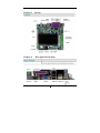
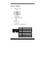
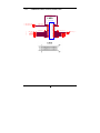
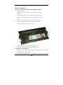
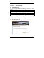
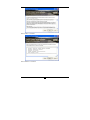
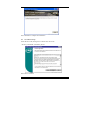
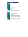
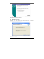
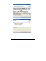
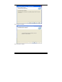
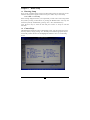
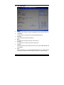
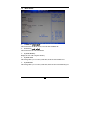
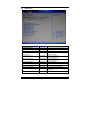
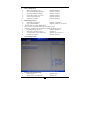
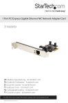
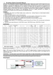
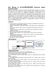
525 Network Application Platform User’s Manual Rev:1.0 Date:2012.03 CONTENTS CHAPTER 1 PACKAGE CONTENTS ....................... 3 CHAPTER 2 INTRODUCTION............................ 4 CHAPTER 3 LAYOUT ................................. 5 CHAPTER 4 REAR PANEL SKETCH MAP .................. 5 CHAPTER 5 INSTALLATION........................... 6 The Interface Definition........................................................................ 6 5.1.1 Function Port Panel ............................................................ 6 5.1.2 USB Extension Interface ..................................................... 6 5.1.3 COM2-COM4 Extension Interface ................................... 6 5.1.4 LVDS Flat Panel Connector:LVDS CON ............................ 7 Jumper Settings ..................................................................................... 8 5.2.1 Jumper Presentation ............................................................ 8 5.2.2 Clear CMOS ........................................................................ 8 5.2.3 LVDS Power Selection Jumper:LCD-PWR ......................... 8 5.2.4 Inverter Power Jumper:INVERTER-PWR .......................... 8 Memory installation .............................................................................. 9 5.3.1 The system board supports One DDRIII SO-DIMM ........... 9 5.3.2 IDE Devices Installation ..................................................... 9 Other Device Installation .................................................................... 10 CHAPTER 6 DRIVER INSTALLATION ................... 12 6.1 Installation Directory ................................................................... 12 6.2 Intel Chipset Software Setup ....................................................... 12 6.3 VGA Driver Setup ........................................................................ 14 6.4 NETWORK Driver Setup ............................................................ 16 CHAPTER 7 BIOS SETUP............................. 19 1 7.1 Entering Setup .............................................................................. 19 7.2 Control keys .................................................................................. 19 7.3 The Menu Bar ............................................................................... 20 7.4 Main menu .................................................................................... 21 7.5 Advanced ....................................................................................... 22 7.6 PCIPnP .......................................................................................... 25 7.7 Boot ................................................................................................ 26 7.8 Security .......................................................................................... 26 7.9 Chipset ........................................................................................... 26 7.10 EXIT ......................................................................................... 28 CHAPTER 8 WATCHDOG PROGRAMMING INSTRUCTIONS ...... 29 Port explain .......................................................................................... 29 Example................................................................................................ 29 CHAPTER 10 ENVIRONMENT ........................... 30 2 Chapter 1 Package Contents Your mainboard package contains the following items: 1 One D525 mainboard 2 SATA data cable 3 Drives installed CD 4 One user’s manual 3 Chapter 2 Introduction Key Features: -Chipset: Intel ATOM D525 + ICH8M -CPU: An onboard low-power INTEL Atom® processors, main frequency D525 as 1.80GHZ, 1MB L2 cache, supports Hyper-Threading technology, which is run at the two thread task. -Memory: Supports DDR3 800 Single Channel Mode Provides 200pin SO-DIMM DDR3 slots -I/O : - Provides two channel connecting two SATA drives With speed up to 300MB/S Four serial port One LPT port One VGA port Four USB ports -Onboard network Card Onboard two RTL8111DL network Card -Expansion slot: One 32-bit PCI slots 2.3 specification compliant One Mini PCIE port -Power supply: ATX standard power mode. 4 Chapter 3 Chapter 4 Layout Rear panel sketch map 5 Chapter 5 Installation The Interface Definition 5.1.1 Function Port Panel FPIO1 USB Extension Interface USB2 5.1.2 5.1.3 COM2-COM4 Extension Interface 2 10 1 9 Pin # 1 2 3 4 5 6 7 8 9 10 Signal Name DCD, Data carrier detect DSR, Data set ready RXD, Receive data RTS, Request to send TXD, Transmit data CTS, Clear to send DTR, Data terminal ready RI, Ring indicator GND, ground COM VCC 6 5.1.4 LVDS Flat Panel Connector:LVDS CON L_VDD_VLD LVDS DF-13-15X2 1 LVDS_DDC_CLK 1 LVDS_DDC_DATA 1 1 1 1 1 L_BKLTEN_V LACLKP LADATAP2 LADATAP1 LADATAP0 L_DDC_CLK_V L_DDC_DATA_V L_BKLTEN_V 29 27 25 23 21 19 17 15 13 11 9 7 5 3 1 29 27 25 23 21 19 17 15 13 11 9 7 5 3 1 LVDS 7 30 28 26 24 22 20 18 16 14 12 10 8 6 4 2 30 28 26 24 22 20 18 16 14 12 10 8 6 4 2 L_BKLTCTL_V L_BKLTCTL_V 1 LACLKN 1 LADATAN2 1 LADATAN1 1 LADATAN0 1 Jumper Settings 5.2.1 Jumper Presentation Pins 1 and 2 are shorted with a jumper cap. 1 2 3 Pins 2 and 3 are shorted with a jumper cap. 1 2 3 5.2.2 Clear CMOS J1 is used to clear the CMOS Data in the RTC. J1 Description Normal Clear CMOS 5.2.3 LVDS Power Selection Jumper:LCD-PWR JP5 Pin # MODE 1 &2short 2 &3short +3.3V +5V 5.2.4 Inverter Power Jumper:INVERTER-PWR JP4 Pin # MODE 1 &2short 2 &3short +12V +5V 8 Memory installation 5.3.1 The system board supports One DDRIII SO-DIMM 1. Single Channel (SC) Data will be accessed in chunks of 64 bits (8B) from the memory channels. 2. A DIM module simply snaps into a DIMM socket on the system board. Pin 1 of the DIM module must correspond with Pin 1 of the socket. 1). Pull the “tabs” which are at the ends of the socket to the side. 2). Position the DIMM above the socket with the “notch” in the module aligned with the “key” on the socket. 3). Seat the module ver tickly into the socket. Make sure it is completely seated. The tabs will hold the DIMM in place. 5.3.2 IDE Devices Installation IDE devices include hard disk drives, high-density diskette drives, and CD-ROM or DVD-ROM drives, among others. The mainboard support one or two IDE devices. If you connect two 9 devices to a single cable, you must configure one of the drives as Master and one of the drives as Slave. The documentation of the IDE device will tell you how to configure the device as a Master or Slave device. The Master device connects to the end of the cable. Other Device Installation 5.4.1 Serial ATA Installation (7-Pin SATA1/SATA3) The motherboard bundles the new Serial ATA technology through the SATA interfaces onboard. The SATA specification allows for thinner, more flexible cables with lower pin count, reduced voltage requirement. These connectors support Serial ATA HDDs and allow up to 300MB/s data transfer rate using thin 4-conductor SATA cables. faster than the standard parallel ATA with 133MB/s(Ultra ATA/133) Note1: The Serial ATA cable is smaller and more flexible allowing easier routing inside the chassis. The lower pin count of the Serial ATA cable eliminates the problem caused by the wide, flat ribbon cables of the Parallel ATA interface. Hot plug support for Serial ATA drive and connections are not available in this motherboard. 5.4.2 Clear CMOS (Clear RTC RAM) This jumper allows you to clear the Real Time Clock (RTC) RAM in CMOS. You can clear the CMOS memory of date, time, and system setup parameters by erasing the CMOS RTC RAM data. The RAM data in CMOS, that include system setup information such as system passwords, is powered by the onboard button cell battery. 1、 Turn OFF the computer and unplug the power cord. 2、 Move the jumper cap from pin 1-2(default) to pin 2-3.Keep the cap on pin 2-3 for about 5-10 seconds, and then move the cap back to pins1-2. 3、 Plug the power cord and turn ON the computer. 4、 Hold down the<F1> key during the boot process and enter BIOS setup to re-enter data. 10 Note1: Except when clearing RTC RAM, never remove the cap on CLRTC1 jumper default position. Removing the cap will cause system boot failure! Note2: You do not need to clear the RTC when the system hangs due to over clocking. For system failure due to over clocking, use the C.P.R. (CPU Parameter Recall) feature. Shut down and reboot the system so BIOS can automatically reset parameter settings to default values. 11 Chapter 6 Driver Installation 6.1 Installation Directory The utility CD is supplied with that mainboard the connects contained in it is showed as below: Directory Driver Inf\INF_9.2.0.1021 Intel chipset software VGA\D410_D510 Intel onboard VGA driver Network\Intel\intel 82574 onboard NETWORK driver OS Windows 2000/XP/Vista Windows 2000/XP/Vista Windows 2000/XP/Vista Before installing audio driver, you must identify the mode of HD Audio codec. Fox example: If you use Related serial codec, you need to enter into the Related directory installing. 6.2 Intel Chipset Software Setup Insert the driver CD, running driver software CD, choose the directory: \ CD-ROM:\ Inf\INF_9.2.0.1021\ INF_allOS_9.2.0.1021_PV Click“NEXT”to continue 12 Select“YES” to continue Select“NEXT” to continue 13 Select“FINISH” to complete the installation. 6.3 VGA Driver Setup Insert the driver CD, running driver software CD, choose the directory:\CD-ROM:\ VGA\D410_D510\ Select“Yes”to continue 14 Select“Next”to continue Continue 15 Select“Finish”to complete the installation 6.4 NETWORK Driver Setup Insert the driver DVD, running driver software DVD, choose the directory: \DVD-ROM:\ Network\Intel\intel 82574\ Select“Next”to continue 16 Select“Next”to continue Select“Next”to continue 17 Select“Install”to continue Select “Finish”to continue 18 Chapter 7 BIOS Setup 7.1 Entering Setup Power on the computer and the system will start POST (Power On Self Test) process. when the message below appears on the screen, press <DEL> key to enter Setup. Press <DEL> to run Setup If the message disappears before you respond and you still wish to enter setup,restart the system by turning it OFF and On or pressing the RESET button. You may also restart the system by simultaneously pressing <Ctrl>,<Alt>,and<Delete>keys. 2.Use the arrow keys to select the item and press <Enter> to accept or enter the sub-menu 7.2 Control keys The BIOS setup program provides a General Help screen. You can call up this screen from any menu by simply pressing <F1>.The Help screen lists the appropriate keys to use and the possible selections for the highlighted item.Press <Esc> to exit the Help screen. 19 7.3 The Menu Bar Main Use this menu for basic system configurations, such as time, date, etc. Advanced Use this menu to set up the items of special enhanced features. PCIPnP Setup PnP and PCI interface parameter. Boot Use this menu to specify the priority of boot devices. Security Use this menu to set supervisor and user passwords. Chipset This menu controls the advanced features of the onboard Host Bridge and South Bridge. Exit This menu allows you to load the BIOS default values or factory default settings into the BIOS and exit the BIOS setup utility or without changes. 20 7.4 Main menu AMIBIOS (read only) These items show the BIOS version, write the date and BIOS ID Processor (read only) These items show the CPU information System Memory Display the size of the computer memory System Time This setting allows you to set the system time, format for hours/minutes/sec System Date This setting allows you to set the system date, format for the week/month/day/year 21 7.5 Advanced Feature Advanced Settings CPU Configuration IDE Configuration Hardware Health Configuration ACPI Configuration Option Menu item Menu item Menu item AHCI Configuration Menu item ASF Configuration MPS Configuration PCI Express Configuration Smbios Configuration Trusted Computing Menu item Menu item Menu item Menu item Menu item USB Configuration Menu item Menu item Description Options for CPU Configure the IDE devices Configure/monitor the Hardware Health Section for Advanced ACPI Configuration Section for Advanced AHCI Configuration Options for ASF MPS Version Control for OS PCI Device Settings options System Management BIOS Whether to support the TCG/TPM USB Device Settings options 22 CPU Configuration Max CPUID Value Limit Default: Disabled Execute-Disable Bit Capability Default: Enabled Hyper Threading Technology Default: Enabled Intel® SpeedStep (tm) tech Default: Disabled Intel® C-STATE tech Default: Enabled Enhanced C-States Default: Enabled IDE Configuration ATA/IDE Configuration Default: Compatible Legacy IDE Channels Default: SATA Pri, PATA Sec Primary IDE /Secondary Master/Slave Press <Enter> to enter the sub menu of detailed options. Ordinarily, The BIOS will automatically detect the IDE drives type. Hard Disk Write Protect Default: Disabled IDE Detect Time Out (Sec) Default: 35 ATA(PI) 80Pin Cable Detection Default: Host & Device Enhanced C-States Default: Enabled ACPI Configuration General ACPI Configuration Suspend mode Repost Video on S3 Resume Default: Auto Default: No 23 Advanced ACPI Configuration ACPI Version Features ACPI APIC support AMI OEMB table Headless mode Default: ACPI v1.0 Default: Enabled Default: Enabled Default: Disabled Chipset ACPI Configuration Energy Lake Feature APIC ACPI SCI IRQ USB Device Wakeup From S3/S4 High Performance Event Timer HPET Memory Address Default: Default: Default: Default: Default: Disabled Disabled Disabled Enabled FED00000h AHCI Configuration SATA Port0 S.M.A.R.T Default: Auto Default: Enabled SATA Port0: Select the type of device connected to the system S.M.A.R.T: (Self-Monitoring Analysis and Reporting Technology) is a utility that monitors your disk status to predict hard disk failure. 24 PCI Express Configuration Relaxed Ordering Maximum Payload Size Extended Tag Field No Snoop Maximum Read Request Size Active State Power Management Extended Synch USB Configuration Legacy USB Support USB 2.0 Controller Mode BIOS EHCI Hand-Off USB 3.0 Controller Mode BIOS XHCI Hand-OFF Hotplug USB FDD Support USB Mass Storage Device Configuration USB Mass Storage Reset Delay Emulation Type Default: Auto Default: Auto Default: Auto Default: Auto Default: Auto Default: Disabled Default: Auto Default: Enabled Default: HiSpeed Default: Enabled Default: Enabled Default: Enabled Default: Auto Default: 20 Sec Default: Auto 7.6 PCIPnP Advanced PCI/PnP Settings Clear NVRAM Plug & Play O/S PCI Latency Timer Allocate IRQ to PCI VGA Palette Snooping PCI IDE BusMaster OffBoard PCI/ISA IDE Card Default: No Default: No Default: 64 Default: Yes Default: Disabled Default: Enabled Default: Auto IRQ3 IRQ4 IRQ5 IRQ7 IRQ9 IRQ10 IRQ11 IRQ14 IRQ15 Default: Available Default: Available Default: Available Default: Available Default: Available Default: Available Default: Available Default: Available Default: Available 25 7.7 Boot Boot Settings Configuration Quick Boot Quiet Boot AddOn ROM Display Mode Bootup Num-Lock PS/2 Mouse Support Wait For ‘F1’ If Error Hit ‘DEL’ Message Display Interrupt 19 Capture Default: Enabled Default: Disabled Default: Force BIOS Default: On Default: Auto Default: Enabled Default: Enabled Default: Disabled Boot Settings Configuration 1st Boot Device 2st Boot Device [USB:USB Hotplug FD] [SATA: xxxxxxxxx] Specifies the boot sequence from the available devices. Click [+] [-] can change the boot sequence 7.8 Security If you Change Supervisor Password Default: Not Installed Change User Password Default: Not Installed Boot Sector Virus Protection Default: Disabled highlight this item and press Enter, a dialog box appears that you can enter a supervisor password. You can enter no more than six letters or numbers. Press Enter after you have typed in the password. There will be the second dialog box asking you to retype the password for confirmation. Press Enter after you have retyped it correctly. Then the password is required for the access to the setup utility or for it at start-up, depending on the setting of the password check item in advanced setup. 7.9 Chipset North Bridge Chipset Configuration DRAM Frequency Configure DRAM Timing by SPD Default: Auto Default: Enabled Initate Graphic Adapter Internal Graphics Mode Select Default: IGD Default: Enabled, 8MB PEG Port Configuration ▶ Video Function Configuration Video Function Configuration 26 DVMT Mode Select DVMT/FIXED Memory Boot Display Device Flat Panel Type Backlight Control Support BIA Connector TV Standard Spread Spectrum Clock Default: DVMT Mode Default: 256MB Default: VBIOS-Default Default: 640x480LVDS Default: VBIOS-Default Default: VBIOS-Default Default: VBIOS-Default Default: Disabled South Bridge Chipset Configuration USB Functions USB 2.0 Controller HDA Controller SMBUS Controller SLP_S4# Min. Assertion Width Restore on AC Power Loss Default: 10 USB Ports Default: Enabled Default: Disabled Default: Enabled Default: 1 to 2 seconds Default: Last State Bypass1 Bypass2 Default: Disabled Default: Disabled PCIE Ports Configuration PCIE Port 0 PCIE Port 1 PCIE Port 2 PCIE Port 3 PCIE Port 4 PCIE Port 5 PCIE High Priority Port Default: Auto Default: Auto Default: Auto Default: Auto Default: Auto Default: Auto Default: Disabled PCIE Port 0 IOxAPIC Enable PCIE Port 1 IOxAPIC Enable PCIE Port 2 IOxAPIC Enable PCIE Port 3 IOxAPIC Enable PCIE Port 4 IOxAPIC Enable PCIE Port 5 IOxAPIC Enable Default: Default: Default: Default: Default: Default: Disabled Disabled Disabled Disabled Disabled Disabled PCIE Port 0-PCIE Port 5 Default value selection Disabled, can be closed nic 1-5 . 27 7.10 EXIT Save Changes and Exit After you have finished the configuration of BIOS, save your settings and exit setup utility. Select “Save Changes and Exit” and press <Enter>, the following message will display, type “Y” and press <Enter> to confirm. Discard Changes and Exit After you have finished the configuration of BIOS, If you do not want to save the settings and exit setup utility. Select “Discard Changes and Exit” and press <Enter>, the following message will display, type “Y” and press <Enter> to confirm. Discard Changes If you do not want to save the settings, select “Discard Changes” to don’t exit setup utility without saving any change. Load Optimal Defaults If you select this item and press enter a dialog box appears. If you press Y, and then Enter, the setup utility loads a set of best-performance default values. These default values are quite demanding and your system might not function properly if you are using slower memory chips or other low-performance components. Load Failsafe Defaults The safest default settings. You can use this function to detect the errors. Select this item and press <Enter>, the following message will display, type in “Y” to load the default values, type “N” to cancel. 28 Chapter 8 Watchdog Programming Instructions Port explain 2EH: 2FH: Address register Data registers Example Set Watchdog Timer for 30 seconds In the DOS mode DEBUG command -----------------------------------------------------------------C:\>debug -o 2e 87 -o 2e 87 ; unlock -o 2e 2d -o 2f e0 ; bit4=0, set pin as wathdog func -o 2e 07 -o 2f 08 ; Choose logic device -o 2e 30 -o 2f 01 ; Activate logic device -o 2e f5 -o 2f 00 ; Set time unit for seconds (Set time unit for minutes o 2f 08) -o 2e f6 -o 2f 30 ; Set Timer Count h 30h= 48 seconds -o 2e aa ; Lock registers -q C:\> -----------------------------------------------------------------After the last line of user input after enter, system in 48 seconds after time reboot 29 C++ language Reference code -----------------------------------------------------------------outputb (0x2e, 0x87) outputb (0x2e, 0x87) //open SUPER IO register outputb (0x2e, 0x2D) outputb (0x2f, 0xE0) //bit4=0, set pin as watchdog func outputb (0x2E, 0x07) outputb (0x2F, 0x08) //Select logical device outputb (0x2e, 0x30) outputb (0x2f, 0x01) //active the device outputb (0x2e, 0xF5) outputb (0x2f, 0x00) //Set time unit for seconds (Set minutes outputb (0x2f, 0x08) outputb (0x2e, 0xF6) outputb (0x2f, 0x30) // Set Timer Count h 30h= 48 seconds outputb (0x2E, 0xAA) // Lock SUPER IO registers //---------- code end --------------------------------------------------------------------------If there was a system crash, through the watchdog function make the system reboot. Chapter 10 Environment Operating temperature:0℃ to 60℃ Storage temperature:-20℃ to 80℃ Relative humidity:10% to 90% (Non self-solidifying) 30