1
RESTORIS MCK Planning and
Surgical Technique Guide
206591-15 Rev 00
This page intentionally left blank
RESTORIS MCK Planning and Surgical Technique Guide
Table of Contents
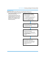
INTRODUCTION ................................................................................................... 1
DESCRIPTION ...................................................................................................... 3
INDICATIONS FOR USE ...................................................................................... 4
CONTRAINDICATIONS ........................................................................................ 5
PATIENT SELECTION.......................................................................................... 6
WARNINGS AND PRECAUTIONS....................................................................... 7
IMPLEMENTATION USING RIO........................................................................... 8
INSTRUMENTATION ............................................................................................ 8
PRE-OPERATIVE IMPLANT PLANNING............................................................. 9
BONE PIN PLACEMENT .................................................................................... 17
INCISION AND EXPOSURE ............................................................................... 17
PRE-RESECTION JOINT BALANCING ............................................................. 20
INTRA-OPERATIVE IMPLANT PLANNING ....................................................... 22
BONE PREPARATION ....................................................................................... 25
MANUAL PEG AND KEEL PREPARATION ...................................................... 28
TRIAL REDUCTION AND IMPLANTATION....................................................... 32
PATELLA PREPARATION ................................................................................. 42
RESTORIS MCK TECHNICAL DATA ................................................................ 47
APPENDIX A....................................................................................................... 53
APPENDIX B....................................................................................................... 71
APPENDIX C....................................................................................................... 90
i
This page intentionally left blank
RESTORIS MCK Planning and Surgical Technique Guide
INTRODUCTION
RESTORIS MCK Inlay component is not approved for use in Australia and New
Zealand.
User Manual Terms of Use
This manual is provided by MAKO Surgical Corp. (‘MAKO’) and may be used for
informational purposes only. Terms and Conditions related to the use of the Robotic Arm
Interactive Orthopedic System (RIO) can be found in the MAKOplasty agreement with the
system user.
About This Manual
This manual describes design considerations, patient selection, implant planning and
surgical techniques for implantation of the RESTORIS MCK implant system using both
manual instrumentation and assisted by the Robotic Arm Interactive Orthopedic System
(RIO). The latter procedure will be identified as MAKOplasty in this manual.
Manufacturer Support/Feedback
MAKO Surgical Corp.
2555 Davie Rd. Ft. Lauderdale, FL 33317
Corporate Office Phone +1 (954) 927-2044
Corporate Office Fax
+1 (954) 927-0446
makosurgical.com
Medical and Product Information
This manual is informational only and is not intended as medical advice or a substitute for
medical advice. As the manufacturer of medical devices in the field of orthopedics, MAKO
does not practice medicine and does not recommend the surgical techniques referenced
or discussed in this manual or any other surgical techniques for use on a particular patient.
MAKO is not responsible for selection of the appropriate surgical technique to be utilized
for an individual patient.
Indications for Use-RESTORIS PKA
The RESTORIS Partial Knee Application (PKA) for use with the Robotic Arm Interactive
Orthopedic System (RIO) is intended to assist the surgeon in providing software defined
spatial boundaries for orientation and reference information to anatomical structures
during orthopedic procedures.
The RESTORIS Partial Knee Application (PKA) for use with the Robotic Arm Interactive
Orthopedic System (RIO) is indicated for use in surgical knee procedures, in which the use
of stereotactic surgery may be appropriate, and where reference to rigid anatomical bony
structures can be identified relative to a CT based model of the anatomy. These
1
RESTORIS MCK Planning and Surgical Technique Guide
procedures include unicondylar knee replacement and/or patellofemoral knee
replacement.
Copyrights and Trademarks
The content of this manual is protected under applicable copyright and trademark laws.
You agree that you will not copy, distribute, republish, display, post, transmit or modify any
content in this manual without MAKO’s prior permission. Any images displayed in this
manual are the property of their respective copyright owners. Any reproduction,
replication, modification or distribution of any art images in this manual is prohibited. The
third-party trademarks in this manual are proprietary to their respective owners. These
companies or their agents have granted MAKO the right to use their trademarks.
Trademarks registered in the United States. Trademark registrations pending in other
jurisdictions.
RIO is a registered trademark of MAKO Surgical Corp.
MAKOplasty is a registered trademark of MAKO Surgical Corp.
RESTORIS is a registered trademark of MAKO Surgical Corp.
Governing Law
Any legal action or proceeding related to this manual or the information contained in it shall
be brought exclusively in a court in Broward County, Florida, and shall be governed by the
laws of the State of Florida, without regard to conflicts of laws principles.
Software Version 2.5
There are no user serviceable parts in the RIO, refer to your MAKO authorized
personnel for service.
2
RESTORIS MCK Planning and Surgical Technique Guide
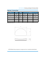
DESCRIPTION
The RESTORIS MCK (MultiCompartmental Knee) Implant System consists of two
subsystems: RESTORIS MCK Unicondylar (Uni) which has an inlay* and onlay option, and
RESTORIS MCK Patellofemoral (PF). These two subsystems may be used independently
or together in a medial multicompartmental implant system referred to in this manual as
the MCK Bicompartmental Inlay* or MCK Bicompartmental Onlay. See the end of this
manual for technical data of all implants.
Medial or Lateral Unicondylar Inlay* or Onlay
Patellofemoral
Medial Bicompartmental Inlay* or Onlay
(Patella Dome not pictured)
Figure 1. RESTORIS MCK Configuration
*RESTORIS MCK Inlay component is not approved for use in Australia and New Zealand.
3
RESTORIS MCK Planning and Surgical Technique Guide
INDICATIONS FOR USE
RESTORIS MCK Uni
RESTORIS MCK Uni components are for use in unicompartmental knee arthroplasty as a
result of: moderately disabling joint disease of the knee resulting from painful osteo- or
post-traumatic arthritis, revision of previous unsuccessful unicompartmental knee
replacement or as an alternative to tibial osteotomy in patients with unicompartmental
osteoarthritis. These components are single use only and are intended for implantation
with bone cement.
The indication above regarding the use of RESTORIS MCK Uni for revision of
previous unsuccessful unicompartmental knee replacement is not approved in the
EU.
RESTORIS MCK PF
RESTORIS MCK PF is intended to be used in cemented patellofemoral arthroplasty in
patients with degenerative arthritis in the distal femur and patella, patients with a history of
patellar dislocation or patella fracture, or patients with failed previous surgery (arthroscopy,
tibial tubercle elevation, lateral release) where pain, deformity or dysfunction persists.
These components are single use only and are intended for implantation with bone
cement.
RESTORIS MCK Bicompartmental
RESTORIS MCK Bicompartmental is indicated for single or multicompartmental knee
replacement used in conjunction with the RIO, Robotic Arm Interactive Orthopedic
System, in individuals with osteoarthritis or post-traumatic arthritis of the tibiofemoral and/
or patellofemoral articular surfaces.
The specific knee replacement configurations include:
•
Medial unicondylar
•
Lateral unicondylar
•
Patellofemoral
•
Medial bi-compartmental (medial unicondylar and patellofemoral)
RESTORIS MCK is for single use only and is intended for implantation with bone cement.
4
RESTORIS MCK Planning and Surgical Technique Guide
CONTRAINDICATIONS
RESTORIS MCK Uni and RESTORIS MCK PF
RESTORIS MCK (Uni or PF) is contraindicated in patients:
•
with greater than 10° of hyperextension, greater than 10° of varus or valgus deformity
(Unicondylar only)
•
with active infection
•
with either mental or neuromuscular disorders that do not allow control of the knee
joint
•
whose weight, age or activity level might cause extreme loads and early failure of the
system
•
without sufficient bone stock to allow appropriate insertion and fixation of the
prosthesis
•
without sufficient soft tissue integrity to provide adequate stability
RESTORIS MCK Bicompartmental
The use of RESTORIS MCK Uni and RESTORIS MCK PF simultaneously for multi
compartmental knee replacement is contraindicated in patients:
•
with greater than 10° of hyperextension, greater than 10° of varus or valgus deformity
•
with active, local infection or previous intra-articular infection
•
with neuropathic (Charcot) joint
•
with cruciate and collateral ligament insufficiency
•
with skeletal immaturity
•
with either mental or neurologic conditions that do not allow control of the knee joint or
that tend to preempt the patient’s ability or willingness to restrict activities
•
without sufficient soft tissue integrity to provide adequate stability
•
without sufficient bone stock to allow appropriate insertion and fixation of the
prosthesis
•
whose weight, age or activity level might cause extreme loads and early failure of the
system
5
RESTORIS MCK Planning and Surgical Technique Guide
PATIENT SELECTION
Selection of multicompartmental knee replacement depends on the judgment of the
surgeon with regard to the requirements of the patient. The surgeon should become
thoroughly familiar with the technique of implantation for multicompartmental knee surgery
by 1) appropriate reading of the literature, and 2) training in the operative skills and
techniques required for multicompartmental knee replacement surgery.
The operative surgeon has final decision authority in choosing recipients of the
MAKOplasty procedure. The effectiveness of all knee implants can be reduced by
poor patient selection.
Additional Patient Selection Guidelines/Considerations
•
Articulation of the hip joint is necessary to complete bone registration
•
Metal in the operative or non-operative leg can lead to the creation of accuracyreducing artifacts in the CT scan which can adversely affect the operative plan
•
The presence of infection (including history of infection), acute or chronic, local or
systemic must be considered
•
Insufficient bone quality may affect the stability of the implant
•
Patient size may complicate the resection procedure. Body Mass Index should be
considered
•
Loss of ligament structures may prevent creation of an ideal intra-operative plan
•
The significance of the deformity (Hyperextension, Flexion Contracture or Varus/
Valgus) must be considered
•
Patients with inflammatory arthritis or tricompartmental disease are not candidates for
the procedure
6
RESTORIS MCK Planning and Surgical Technique Guide
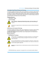
WARNINGS AND PRECAUTIONS
Familiarity with and attention to appropriate surgical technique for unicondylar,
patellofemoral, multicompartmental arthroplasty, and RESTORIS MCK is essential for
success of the procedure.
Only surgeons who have reviewed the literature regarding unicondylar and
multicompartmental knee replacement and have had training in the technique using RIO
should perform this procedure.
The surgeon or his designee should instruct patients in the limitations of
multicompartmental knee replacement, and these patients should be taught to govern their
activities accordingly.
Implants and trial components from different manufacturers or implant systems should
never be used together since articular and dimensional compatibility cannot be assured.
The use of the RESTORIS MCK Implant system in any configuration requires the use of
the Robotic Arm Interactive Orthopedic System (RIO). For more details on RIO driven
implementation, see the RIO System User Guide (PN 203857-15)and MAKOplasty Partial
Knee Application User Guide (PN 206388-15).
RESTORIS MCK is not for lateral bicompartmental patellofemorotibial replacement
or for tricompartmental knee replacement.
Adverse Effects
As with any knee system, potential adverse effects include infection, loosening of the
components, breakage or bending of the components, or change in position of the
components. There have been reports of sensitivity reactions to the components of knee
replacement systems. Other potential adverse effects of knee surgery include
neurovascular damage, dislocation, thromboembolic disease, and other less common
adverse effects.
Implant Packaging/Sterilization
If any seals or packages are breached, then the component should not be used.
A minimum of 2.5 megarads of gamma irradiation is used for all RESTORIS MCK
components. The UHMWPE components are subjected to gamma sterilization and
packaged in an inert gas environment.
7
RESTORIS MCK Planning and Surgical Technique Guide
IMPLEMENTATION USING RIO
RESTORIS MCK Procedure Options
1. RESTORIS MCK Uni Inlay* (Medial or Lateral)
•
Femoral Condyle*
•
Tibial Inlay*
2. RESTORIS MCK Uni Onlay (Medial or Lateral)
•
Femoral Condyle
•
Tibial Baseplate
•
Tibial Onlay Insert
3. RESTORIS MCK PF
•
Patellofemoral (Trochlear) component
•
Patella component
4. RESTORIS MCK Bicompartmental Inlay* (Medial only)
•
RESTORIS MCK PF + MCK Uni Inlay*
5. RESTORIS MCK Bicompartmental Onlay (Medial only)
•
RESTORIS MCK PF + MCK Uni Onlay
Sizes
All sizes are outlined in the RESTORIS MCK Implant Technical Data section of this
manual.
INSTRUMENTATION
Two instrument trays, a Unicondylar and a Patellofemoral tray are available for use with
the RESTORIS MCK Implant System. Each tray contains instrumentation and implant
trials specific to implementation of that procedure.
Both trays are required when performing a RESTORIS MCK Bicompartmental Inlay*
or Onlay procedure.
All RESTORIS MCK implants require the use of the RIO therefore; a Standard
MAKOplasty Instrument Set is also required.
*RESTORIS MCK Inlay component is not approved for use in Australia and New Zealand.
8
RESTORIS MCK Planning and Surgical Technique Guide
PRE-OPERATIVE IMPLANT PLANNING
The primary purpose of pre-operative planning for the RESTORIS MCK implant system is
implant sizing and alignment to bone anatomy. Fine tuning of the component position and
orientation based on patient specific biomechanics and cartilage thickness will be
completed during the intra-operative steps. Refer to the RIO System User Guide
(PN 203857-15) and MAKOplasty Partial Knee Application User Guide (PN 206388-15) for
software control details.
All varus/valgus and flexion/extension degree references are made with respect to
the mechanical axis of the applicable bone. Internal/External rotations are with
respect to the AP axis of the applicable bone.
General Design Considerations for Implant Planning
•
•
•
Material
-
CoCr and UHMWPE are the industry standard for component articulation.
-
Titanium was chosen for the baseplate because of its high strength and fatigue
resistance.
-
All UHMWPE components are conventional compression molded polyethylene.
They are gamma sterilized in an inert environment.
Fixation
-
All metallic implant pegs have a 6.5 mm diameter, designed to have a slight press
fit with a prepared peg hole when cemented.
-
The Tibial Inlay* has an outer cement channel for high fixation strength.
Compatibility
-
All Femoral Condyle component sizes are compatible with all Tibial Inlay* or
Onlay component sizes (full size compatibility).
-
All Patellofemoral (Trochlear) component sizes are compatible with all Patella
component sizes (full size compatibility).
-
Component sizing for the Bicompartmental Femoral Condyle is limited to one size
larger and one size smaller (1 up / 1 down) than the selected Patellofemoral
(Trochlear) component. This aids in proper patella transitioning.
*RESTORIS MCK Inlay component is not approved for use in Australia and New Zealand.
9
RESTORIS MCK Planning and Surgical Technique Guide
•
Bicompartmental Geometry
-
The Femoral Condyle and Patellofemoral (Trochlear components) were designed
from a single continuous femur articular surface from which the individual
component shapes were outlined. This aids in inter component alignment and in
patella transitioning from the trochlear groove to the femoral condyles during
flexion.
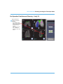
This continuous surface was sectioned into two implant visuals (transition zones)
which act as surface extensions of the Trochlear component. The patellar
transition zones move with the Trochlear component and can be turned on/off.
The transition zones aid in Femoral positioning and Patella transitioning. The
transition zones also have a separation indicator (wall) at 3 mm from the
Patellofemoral (Trochlear) edge, which can be used as a reference to ensure that
a 3 mm gap is maintained between the Femoral and Patellofemoral (Trochlear)
implants.
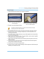
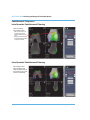
Transition Zones
3 mm Distance Indicators
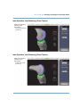
Figure 2. Trochlear transition zones with 3 mm distance indicators
10
RESTORIS MCK Planning and Surgical Technique Guide
•
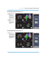
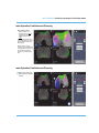
Patellofemoral (Trochlear) Component Geometry
-
The Patellofemoral Component trochlear groove pathway is curved proximally 6
degrees to align with the anatomic axis (when implant is planned at 0 degrees
varus/valgus). The visual of the Patellofemoral (Trochlear) implant contains a
Trochlear sulcus groove (Figure 3) which is a reference to the potential patella
tracking pathway.
Potential Patella
Tracking Pathway
Figure 3. Trochlear Visual
•
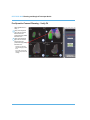
Tibial Component Geometry
-
All UHMWPE components have a minimum 6 mm thickness
Tibial Onlay: An artificial gap is included in the Tibial Onlay component visual
(see Figure 4). This gap does not alter the articular surface of the Insert or any of
the geometry of the Baseplate. The bottom of the gap is the actual superior
surface of the Baseplate Implant or Trial. The gap allows the user to distinguish
the superior Baseplate surface from the inferior Insert surface during planning and
to verify placement in CT View.
Figure 4. Tibial Onlay Visual
11
RESTORIS MCK Planning and Surgical Technique Guide
Tibial Inlay*: To assist in Implant Planning a reference groove is included in the
Tibial Inlay* visual side wall perimeter (Figure 5). The center of the groove is
3.5 mm from the bottom of the implant and the top of the cement channel is
2.5 mm from the bottom of the implant. Per Appendix A, B and C the Inlay* should
not be inset more than 3.5 mm below cortical bone surface.
Groove
Cement
Channel
Figure 5. RESTORIS MCK Inlay* Visualization
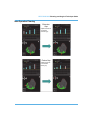
Polymer Thickness Options: As outlined in the MAKOplasty Partial Knee
Application User Guide (PN 206388-15) the available thicker poly options (Inlay*:
7.5 mm and 8.5 mm and Onlay: 9.0 mm and 10.0 mm) can be selected in the
cases, post resection, where a thicker insert must be used.
Always plan and resect using the thinnest poly. This feature is intended ONLY for
analysis during trialing.
When a thicker polyethylene trial is used in the joint, the corresponding thickness
option should be selected in the drop down menu (Figure 5C). Then, as long as
the VISUAL button is enabled, a visual of the surface of the trial will appear in the
3-D (Figure 5A) and 2-D (Figure 5B) views of Implant Planning. These visuals
represent the superior surface of the selected Implant thickness. The CT views,
Implant Planning Graph (Figure 5C) and Tibial Tracking points will update
accordingly when a new poly thickness is selected.
*RESTORIS MCK Inlay component is not approved for use in Australia and New Zealand.
12
RESTORIS MCK Planning and Surgical Technique Guide
Figure 5A.3-D View of Poly Visual
Figure 5B. 2-D View of Poly Visual
Figure 5C. Implant Planning Graph with Poly Thickness Selection
13
RESTORIS MCK Planning and Surgical Technique Guide
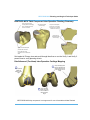
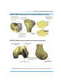
•
Femoral Condyle Geometry
-
The Femoral Condyle component is designed for use when load bearing Range of
Motion (ROM) is expected to be up to 155 degrees.
-
The Femoral Condyle component has a ‘patella relief’ feature on the anterior tip
so as not to impinge with the patella or the Patella component during high flexion
ROM.
-
The visual of the Femoral Condyle contains a high point groove (Figure 6) through
the model that marks a reference for the potential tibial tracking pathway. During
Intra-Op planning the groove can be used to align the Femoral Condyle to the
tracking points collected during Joint Balancing (Pose Capture).
Figure 6. Femoral Condyle Visual
14
RESTORIS MCK Planning and Surgical Technique Guide
Unicondylar Inlay*/Onlay Pre-Operative Planning
For details regarding the following steps, refer to Appendix A for a step by step procedure
to complete Medial Unicondylar Inlay*/Onlay Planning. Appendix A describes the steps
necessary to complete a Bicompartmental Inlay*/Onlay, only the steps specific to a Medial
Unicondylar procedure are relevant. Refer to Appendix C for a step by step procedure to
complete Lateral Unicondylar Inlay*/Onlay Planning.
Planning Sequence
•
Tibial Inlay* / Onlay
•
Femoral Condyle
If the Tibial Inlay* component is planned with less than a 2 mm rim of bone on the
anterior, posterior, or medial sides, the rim may be removed or fractured during
resection.
Adjustments to the plan from the nominal may be necessary to match specific patient
anatomy.
Patellofemoral Pre-Operative Planning
For details regarding the following steps, refer to Appendix A for a step by step procedure
to complete Patellofemoral Planning. Appendix A describes the steps necessary to
complete a Bicompartmental Inlay*/Onlay, only the steps specific to a Patellofemoral
procedure are relevant.
Planning Sequence
•
Patellofemoral (Trochlear)
External rotation of the Patellofemoral (Trochlear) component is not recommended
as it will decrease the lateral patella jump height and increase the risk of lateral
patella subluxation.
Do not put the Patellofemoral (Trochlear) component in more than 2° valgus as this
will align the trochlear groove away from the anatomic axis of the femur and increase
the risk of lateral patella subluxation.
Adjustments to the plan from the nominal may be necessary to match specific patient
anatomy.
*RESTORIS MCK Inlay component is not approved for use in Australia and New Zealand.
15
RESTORIS MCK Planning and Surgical Technique Guide
Bicompartmental Pre-Operative Planning
For details regarding the following steps, refer to Appendix A for a step by step procedure
to complete Bicompartmental Planning.
Planning Sequence
•
Tibial Inlay*/Onlay
•
Bicompartmental (Patellofemoral + Medial Femoral Condyle)
•
Patellofemoral (Trochlear)
•
Femoral Condyle
If the tibial Inlay* component is planned with less than a 2 mm rim of bone on the
anterior, posterior, or medial sides, the rim may be removed or fractured during
resection.
External rotation of the Patellofemoral (Trochlear) component is not recommended
as it will decrease the lateral patella jump height and increase the risk of lateral
patella subluxation.
Do not put the Patellofemoral (Trochlear) component in more than 2° valgus as this
will align the trochlear groove away from the anatomic axis of the femur and increase
the risk of lateral patella subluxation.
Adjustments to the plan from the nominal may be necessary to match specific patient
anatomy.
*RESTORIS MCK Inlay component is not approved for use in Australia and New Zealand.
16
RESTORIS MCK Planning and Surgical Technique Guide
BONE PIN PLACEMENT
For additional information regarding bone pin placement, see the MAKOplasty Partial
Knee Application User Guide (PN 206388-15).
For Patellofemoral or Bicompartmental procedures, femoral bone pins might need to
be more proximally placed to accommodate Patellofemoral (Trochlear) and Patella
preparation.
INCISION AND EXPOSURE
Medial Incision and Exposure
1. With the knee flexed at about 45°, create a skin incision directly over the median
plane of the knee. The underlying arthrotomy will be placed more medially than the
skin incision to prevent wound complications. As a guide for a minimally invasive
technique, the incision should extend from the inferior border of the patella to
approximately 2 cm below the tibial plateau. Extend the incision proximally or distally
as needed for adequate visualization.
2. Undermine the subcutaneous tissues and place retractors to expose the medial
retinaculum.
3. Make a medial parapatellar arthrotomy through the medial retinaculum, capsule, and
synovium. If necessary, extend the arthrotomy proximally by making a medial snip of
the Vastus Medialis Oblique (VMO) at the distal insertion site of the patella (this will
aid in exposure and help mobilize the patella). The length of the incision and
arthrotomy must be sufficient to enable proper patella retraction for femoral prosthesis
insertion, femoral registration, and tibial registration.
4. Inspect all compartments and evaluate the integrity of the Anterior Cruciate Ligament
(ACL) and Posterior Cruciate Ligament (PCL) to confirm the indications for a
unicondylararthroplasty.
5. Elevate the medial capsule from the proximal tibia to the mid-sagittal plane. For an
Inlay* procedure, this may not be required because less tibial exposure is needed. A
medial collateral release should not be performed.
6. Debulk the fat pad as needed for exposure and resect the visible medial meniscus.
7. Reflect patella laterally to expose tibiofemoral joint space.
8. Trim any portions of loose or torn meniscus and release soft tissue from the anterior
surface of the tibia, as needed, for improved exposure and registration.
*RESTORIS MCK Inlay component is not approved for use in Australia and New Zealand.
17
RESTORIS MCK Planning and Surgical Technique Guide
Lateral Incision and Exposure
1. With the knee flexed at about 45°, create a skin incision directly over the median
plane of the knee as lateral soft tissues are extremely thin. The underlying arthrotomy
will be placed more laterally than the skin incision to prevent wound complications. As
a guide for a minimally invasive technique, the incision should extend from the
superior pole of the patella to approximately 2 cm below the tibial plateau. Extend the
incision proximally or distally as needed for adequate visualization.
2. Undermine the subcutaneous tissues and place retractors to expose the lateral
retinaculum.
3. Make a lateral parapatellar arthrotomy through the lateral retinaculum, capsule, and
synovium. The length of the incision and arthrotomy must be sufficient to enable
proper patella retraction for femoral prosthesis insertion and to allow for tibial
registration. In certain circumstances, exposure can be enhanced by lateralizing the
arthrotomy 5-10 mm more lateral to the patella. A ‘T’-shaped cut in the arthrotomy can
help to relax the soft tissues for improved visualization and easier retraction of the
patella medially.
4. Inspect all compartments and evaluate the integrity of the Anterior Cruciate Ligament
(ACL) and Posterior Cruciate Ligament (PCL) to confirm the indications for a
unicondylar arthroplasty.
5. For an Onlay procedure, elevate the lateral capsule from the proximal tibia until
Gerdy’s tubercle is released. For an Inlay* procedure, this may not be required
because less tibial exposure is needed. A lateral collateral release should not be
performed.
6. Debulk the fat pad as needed for exposure and resect the visible lateral meniscus.
Use caution interiorly to preserve the intermeniscal ligament and its attachment to the
proximal tibia. Release of this ligament can destabilize the medial meniscus.
7. Reflect patella medially to expose tibiofemoral joint space.
8. Trim any portions of loose or torn meniscus and release soft tissue from the anterior
surface of the tibia, as needed, for improved exposure and registration.
Patellofemoral Incision and Exposure
1. With the knee flexed at about 45°, create a skin incision directly over the median
plane of the knee. The underlying arthrotomy will be placed more medially than the
skin incision to prevent wound complications. As a guide for a minimally invasive
technique, the incision should extend from the superior border of the patella to the top
of the tibial plateau. Extend the incision proximally or distally as needed for adequate
visualization.
*RESTORIS MCK Inlay component is not approved for use in Australia and New Zealand.
18
RESTORIS MCK Planning and Surgical Technique Guide
2. Undermine the subcutaneous tissues and place retractors to expose the medial
retinaculum.
3. Make a medial sub-vastus or mid-vastus arthrotomy through the medial retinaculum,
capsule, and synovium. The length of the incision and arthrotomy must be sufficient to
enable proper patella retraction for trochlear prosthesis insertion and femoral
registration.
4. Inspect all compartments and evaluate the integrity of the Anterior Cruciate Ligament
(ACL) and Posterior Cruciate Ligament (PCL) to confirm the indications for a
patellofemoral arthroplasty.
5. Debulk the fat pad as needed for exposure and elevate any suprapatellar synovium
for trochlear exposure.
6. Reflect patella laterally to expose patellofemoral joint space.
Bicompartmental Incision and Exposure
1. With the knee flexed at about 45°, create a skin incision directly over the median
plane of the knee. The underlying arthrotomy will be placed more medially than the
skin incision to prevent wound complications. As a guide for a minimally invasive
technique, the incision should extend from the superior border of the patella to
approximately 2 cm below the tibial plateau. Extend the incision proximally or distally
as needed for adequate visualization.
2. Undermine the subcutaneous tissues and place retractors to expose the medial
retinaculum.
3. Make a medial sub-vastus or mid-vastus arthrotomy through the medial retinaculum,
capsule, and synovium. The length of the incision and arthrotomy must be sufficient to
enable proper patella retraction for femoral prosthesis insertion, femoral registration,
and tibial registration.
4. Inspect all compartments and evaluate the integrity of the Anterior Cruciate Ligament
(ACL) and Posterior Cruciate Ligament (PCL) to confirm the indications for a
unicondylar arthroplasty.
5. Elevate the medial capsule from the proximal tibia to the mid-sagittal plane. For an
Inlay* procedure, this may not be required because less tibial exposure is needed. A
medial collateral release should not be performed.
6. Debulk the fat pad as needed for exposure and resect the visible medial meniscus.
7. Reflect patella laterally to expose tibiofemoral and patellofemoral joint space.
8. Trim any portions of loose or torn meniscus and release soft tissue from the anterior
surface of the tibia, as needed, for improved exposure and registration.
*RESTORIS MCK Inlay component is not approved for use in Australia and New Zealand.
19
RESTORIS MCK Planning and Surgical Technique Guide
PRE-RESECTION JOINT BALANCING
Philosophy
For manual medial unicondylar implantation, it is typical for the surgeon to evaluate postresection restoration by insuring the femoral-tibial gap and limb alignment are acceptable
in extension, flexion and for intermediate leg poses while inducing an appropriately applied
valgus stress.
During a MAKOplasty, ligament tension and limb alignment can be established prior to
resection and implantation by ‘capturing’ the leg in corrected poses and tension such that
the final implant placement will achieve the desired result. In other words, with precise
planning prior to resection, it is possible to achieve proper ligament tension and limb
alignment after implantation.
Joint Balancing is not necessary for a Patellofemoral only procedure because the
tibia is not registered.
Either the tibia or the femur can be fixed while the other moves relative to the fixed
bone during Joint Balancing. See the MAKOplasty Partial Knee Application User
Guide (PN 206388-15) for instructions on setting this in Surgeon Preferences.
Eliminate Osteophyte / Adhesion Effects on Joint Mechanics
The Pre-Resection Joint Balancing data must not be adversely influenced by effects of the
osteoarthritic pathology - e.g. osteophytes, capsular adhesions, and osteochondral
defects. Osteophytes interfering with Medial Collateral Ligament (or Lateral Collateral
Ligament for lateral UKA) function should be removed and capsular adhesions interfering
with knee function should be relieved. With these impediments removed, it will be possible
to achieve correct knee kinematics and tissue tension during passive manipulation
throughout the full range of motion.
Pre-Resection Joint Balancing
To achieve correct restoration of the osteochondral defects, joint balancing pose capture
must occur with the collateral ligament properly tensioned. Doing so will provide correct
bone spacing (extension and flexion gaps) during Intra-Op Implant Planning such that after
resection and component implantation, knee mechanics will be properly restored
throughout leg range of motion.
Although this step is referred to as ‘Joint Balancing’, desired joint balancing is achieved in
Intra-Op Implant Planning using the data gathered in this step (bone spacing with properly
tensioned ligaments).
20
RESTORIS MCK Planning and Surgical Technique Guide
Ensure osteophytes are removed prior to taking pose captures for Joint Balancing.
Attempt to apply the appropriate varus or valgus (valgus - medial, varus - lateral)
moment to the tibia at each pose during Joint Balancing for proper tensioning of
ligaments.
It is recommended that the leg is passively corrected to be slightly under corrected
for the ‘extension’ pose capture (5-10° flexion).
Pre-Resection Joint Balancing is necessary for enabling full use of the intra-operative
implant planning features. Medical standard of practice is to acquire a minimum of 4
poses (full extension, full flexion, and 2 additional angles in between). More than 4
pose captures are possible however it is up to the surgeon’s discretion as to how
many poses to capture.
Recommended Pose Captures for Joint Balancing
Listed below are the 4 minimum recommended poses, more poses can be captured
as needed to ensure a successful implant plan.
•
5°-10° (Extension gap balancing)
•
45° (Mid-flexion gap balancing)
•
90° (Flexion gap balancing)
•
100°-120° (Maximum flexion) - this pose is critical for planning the posterior
tibiofemoral articulation during Intra-Operative Planning, especially for a Lateral
Unicondylar procedure.
Refer to Appendix B for step by step visual instructions.
21
RESTORIS MCK Planning and Surgical Technique Guide
INTRA-OPERATIVE IMPLANT PLANNING
During intra-operative planning, patient specific information gathered in the ‘Joint
Balancing’ step is used to adjust the pre-operative implant plan to achieve implant
component positions suitable for resection. Software functionality for this step can be
found in the MAKOplasty Partial Knee Application User Guide (PN 206388-15).
The green models displayed on the ‘Implant Planning’ software page represent the
final locations of the implanted components. However, due to the interaction of the
user with the stereotactic boundaries, the actual resection may be slightly wider at
the implant walls. To prevent malalignment and to preserve bone, always allow
sufficient space between components and size appropriately.
Unicondylar Inlay* / Onlay Intra-Operative Planning
For details regarding the following steps, refer to Appendix B for a step by step procedure
to complete Medial Unicondylar Inlay*/Onlay Planning. Appendix B describes the steps
necessary to complete a Bicompartmental Inlay*/Onlay, only the steps specific to a Medial
Unicondylar procedure are relevant. Refer to Appendix C for a step by step procedure to
complete Lateral Unicondylar Inlay*/Onlay Planning.
Planning Sequence
•
Tibial Inlay*/Onlay
•
Femoral Condyle
If the Tibial Inlay* component is planned with less than a 2 mm rim of bone on the
anterior, posterior, or medial sides, the rim may be removed or fractured during
resection.
Adjustments to the plan from the nominal may be necessary to match specific patient
anatomy.
*RESTORIS MCK Inlay component is not approved for use in Australia and New Zealand.
22
RESTORIS MCK Planning and Surgical Technique Guide
Patellofemoral Intra-Operative Planning
For details regarding the following steps, refer to Appendix B for a step by step procedure
to complete Patellofemoral Planning. Appendix B describes the steps necessary to
complete a Bicompartmental Inlay*/Onlay, only the steps specific to a Patellofemoral
procedure are relevant.
Planning Sequence
•
Patellofemoral (Trochlear)
Ensure the Patellofemoral (Trochlear) component is not in excessive external
rotation or valgus, as these will decrease the lateral patella jump height and increase
the risk of lateral patella subluxation.
The proximal edge of the Patellofemoral (Trochlear) component can transition into
the bone in three ways:
Proud - the articular surface is proud (cemented surface rests on top of the bone)
Medium - halfway between proud and flush
Flush - the articular surface is flush with the bone
Bicompartmental Intra-Operative Planning
For details regarding the following steps, refer to Appendix B for a step by step procedure
to complete Bicompartmental Planning.
Planning Sequence
•
Tibial Inlay*/Onlay
•
Patellofemoral (Trochlear)
•
Femoral Condyle (Medial)
Ensure the Patellofemoral (Trochlear) component is not in excessive external
rotation or valgus, as it will decrease the lateral patella jump height and increase the
risk of lateral patella subluxation.
The proximal edge of the Patellofemoral (Trochlear) component can transition into
the bone in three ways:
Proud - the articular surface is proud (cemented surface rests on top of the bone)
Medium - halfway between proud and flush
Flush - the articular surface is flush with the bone
*RESTORIS MCK Inlay component is not approved for use in Australia and New Zealand.
23
RESTORIS MCK Planning and Surgical Technique Guide
Implant Planning After Initial Resection
Care must be taken when choosing to adjust an implant plan after resection has
taken place. Since the software tracks only the latest change to an implant plan, a
plan can be created which overlaps a previous resection. To prevent implant
malalignment or component impingement, the operative surgeon should check
component placement with the RIO probe before a change to the plan is made.
Any component can be re-planned and/or resized (and subsequently resected again) after
an initial resection using any of the implant planning features. The following issues should
be considered before changing a component plan after initial resection:
•
Any system configuration (Unicondylar, Patellofemoral or Bicompartmental)
-
The software will not save the previous plan once a change to the plan is
made.The old plan will be overwritten. The ‘undo’ button may be used, but only
the latest (new) plan will be applied when returning to the ‘Bone Preparation’ page
-
Any change which causes the implant to become more proud of the bone will not
be represented in the software (i.e., resected bone cannot be restored).
-
A conversion from Tibial Inlay* to Onlay will align the initial Tibial Onlay plan with
the articular surface of the previous Inlay* component
Detailed instructions on software functionality can be found in the MAKOplasty Partial
Knee Application User Guide (PN 206388-15).
*RESTORIS MCK Inlay component is not approved for use in Australia and New Zealand.
24
RESTORIS MCK Planning and Surgical Technique Guide
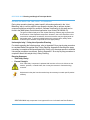
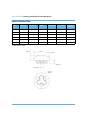
BONE PREPARATION
Even with stereotactic boundaries, the burr can contact nearby tissue. To avoid risk
of serious injury, use a retractor to protect the medial or lateral collateral ligament
during Tibial Onlay resection.
To create proper press fit with the implant peg, gently plunge the burr only once then
release the trigger and move to the next step. Plunging more than once can create a
larger hole and prevent the peg from fitting snuggly.
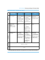
Table 1 is a list of resection steps for each procedure. All steps marked with an ‘X’ are to
be completed with the 6 mm Ball Burr; others are noted. All of the listed steps should be
implemented using the technique listed in this manual. The order of resection, tibial keel
router choice and Inlay* pattern are surgeon preference combinations that can be adjusted
in the Preferences page.
Table 1. Resection Steps for RESTORIS MCK
(All steps marked with an ‘X’ are to be completed with the 6 mm Ball Burr)
Unicondylar
(Uni) Inlay*
Unicondylar
(Uni) Onlay
Femoral Surface
x
x
x
x
Femoral Post 1
x
x
x
x
Femoral Post 2
x
x
x
x
Femoral Keel1
x
x
x
x
Tibial Inlay* Surface4
x
Patellofemoral
Bicompartmental Bicompartmental
Inlay*
Onlay
x
Tibial Onlay Surface
x
x
Tibial Post 1
x
x
Tibial Post 2
x
x
Tibial Keel*2
2 mm/1.4 mm
Router
2 mm/1.4 mm
Router
Patellofemoral Surface
x
x
x
Patellofemoral Post 1
x
x
x
Patellofemoral Post 2
x
x
x
Patellofemoral Post 3
x
x
x
*RESTORIS MCK Inlay component is not approved for use in Australia and New Zealand.
25
RESTORIS MCK Planning and Surgical Technique Guide
Table 1. Resection Steps for RESTORIS MCK
(All steps marked with an ‘X’ are to be completed with the 6 mm Ball Burr)
Unicondylar
(Uni) Inlay*
Unicondylar
(Uni) Onlay
Patellofemoral
Manual
Preparation
Patella Resection3
Bicompartmental Bicompartmental
Inlay*
Onlay
Manual
Preparation
Manual
Preparation
Notes:
1
Femoral keel resection is only applicable to sizes 3-8.
2
The Tibial Onlay Keel may be prepared in a medial or lateral procedure by impacting the
Tibial Onlay Trial, however RIO access for a lateral unicondylar procedure can be
challenging so using the trial is the recommended method of lateral keel resection.
3
Preparation of the patella uses the Patella Preparation Section of this manual.
4
The Tibial Inlay* has a surgeon preference setting that allows resection with (Figure 8)
or without (Figure 7) the clover pattern boundary. Using the clover pattern leaves four small
sections of bone that fit closer to the Inlay* component to help stabilize the Inlay* Trial and
Implant during cementing.
Figure 7.RESTORIS MCK Inlay* Resection
WITHOUT Clover Pattern
Figure 8. RESTORIS MCK Inlay* Resection
WITH Clover Pattern
*RESTORIS MCK Inlay component is not approved for use in Australia and New Zealand.
26
RESTORIS MCK Planning and Surgical Technique Guide
Conversion from RESTORIS MCK Inlay* to RESTORIS MCK Onlay
Under no circumstances should a conversion from the RESTORIS MCK Implant
System to the RESTORIS Implant System be performed. The implant geometries are
not equivalent. Mixing incompatible implant systems could shorten implant life.
Conversion from the RESTORIS MCK Inlay* to the RESTORIS MCK Onlay can occur at
any time. This conversion is done at the discretion of the operative surgeon. To convert,
follow the steps outlined below.
1. Clear RESTORIS MCK Inlay* instrumentation and trials from surgical field before
bringing in RESTORIS MCK Onlay instrumentation and trials.
2. Select the new Tibial component per the MAKOplasty Partial Knee Application User
Guide (PN 206388-15).
3. Return to Implant Planning and make any adjustments to the plan to ensure proper
Tibial Onlay placement.
4. Proceed to RESTORIS MCK Onlay resection.
When converting from a RESTORIS MCK Inlay* to RESTORIS MCK Onlay system
(Bicompartmental or Uni), the software application will align the articular surfaces of
each tibial component at the same height in the ‘Implant Planning’ page.
*RESTORIS MCK Inlay component is not approved for use in Australia and New Zealand.
27
RESTORIS MCK Planning and Surgical Technique Guide
MANUAL PEG AND KEEL PREPARATION
Prerequisites
The manual resection of the RESTORIS MCK is for use when implant surface pockets
have been resected and only the pegs and keels need resection or correction.
No instrumentation exists for resecting RESTORIS MCK surface manually. Available
instrumentation is applicable to peg and keel resection only.
Manual Instrumentation
The RESTORIS MCK Manual Technique uses the RESTORIS MCK Manual Instrument
Set.
Instruments are provided separately in re-usable/sterilizable trays. Trays include various
tools (e.g., templates and drills) needed for a RESTORIS MCK manual procedure.
The steps in this section are guidelines and do not constitute a complete surgical
technique.
28
RESTORIS MCK Planning and Surgical Technique Guide
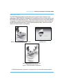
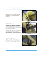
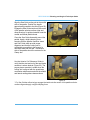
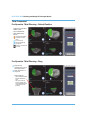
Femoral Condyle Component
Affix the Femoral Template to the resected
bone pocket using the Headed Bone Pins
and the Pin Pusher (Figure 9).
Figure 9
Drill the peg holes for the Femoral Condyle
Implant using the Femoral Peg Drill (Figure
10).
Mark the position of the keel using a sterile
marker.
Figure 10
Remove the Headed Bone Pins from the
bone using the Pin Puller and remove the
Femoral Template (Figure 11).
Figure 11
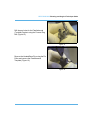
29
RESTORIS MCK Planning and Surgical Technique Guide
Resect the keel using a 6 mm burr to the
depth shown on the Femoral Template
(Figure 12).
Figure 12
Tibial Onlay Baseplate
Attach the Onlay Handle to the Baseplate
Template. Align the Baseplate Template to
the resected tibial profile and impact into
place with a mallet. Confirm that the template
is fully seated on the tibia.
Drill peg holes for the Tibial Baseplate using
the Patellar/Tibial Peg Drill (Figure 13).
Remove Baseplate Template from the tibia.
Figure 13
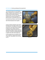
Patellofemoral Template
Affix the Patellofemoral Template to the
resected bone pocket using the Headed
Bone Pins and the Pin Pusher (Figure 14)
Figure 14
30
RESTORIS MCK Planning and Surgical Technique Guide
Drill the peg holes for the Patellofemoral
(Trochlear) Implant using the Femoral Peg
Drill (Figure 15).
Figure 15
Remove the Headed Bone Pins using the Pin
Puller and remove the Patellofemoral
Template (Figure 16).
Figure 16
31
RESTORIS MCK Planning and Surgical Technique Guide
TRIAL REDUCTION AND IMPLANTATION
The steps in this section are guidelines and do not constitute a complete surgical
technique.
Care should be used in the handling of the implant components to minimize damage
to the component surfaces. The surgeon should use care to ensure complete cement
support on all parts of the prosthesis contacting resected bone. It is important to
pressurize cement into both tibial and femoral peg holes.
Implants must not be reused. The surgeon must not allow damage to polished
bearing surfaces because this may accelerate wear of the implant components. Any
alteration or damage to an implant component may result in failure under load. Any
prostheses so damaged must not be used.
Care should be used when inserting (impacting) a trial or implant. If the initial fit is too
tight, impaction could damage the bone. Return to the BONE PREPARATION
section if more bone must be removed.
Do not place excessive off-center shear loads on the implant component until the
cement has cured. These types of loads could cause improper implant-to-cement-tobone fixation and could shorten implant life.
For proper fixation, the knee must be kept stationary while cement cures. If the leg is
moved during curing, the implant components may move from their intended
positions.
Multiple cement batches should be used when cementing multiple implants to
maintain a consistent and suitable cement viscosity that 1) enables all implants to
fully mate to resected bone to ensure desired alignment, 2) enables sufficient cement
interdigitation into the cancellous bone to ensure proper fixation, and 3) enables the
user to apply an even distribution of compressive force to ensure the implant remains
stable while the cement is setting.
32
RESTORIS MCK Planning and Surgical Technique Guide
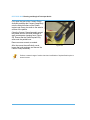
Femoral Condyle
1. Insert the selected size Femoral Trial, impact as applicable.
Figure A: One-Piece RESTORIS MCK
Femoral Impactor
Figure B: Proper impaction technique when
using the Femoral Impactor. Align impactor
with Trial / Implant Peg axis.
2. Rongeur any proud cartilage and bone.
To facilitate component insertion it may help to insert the Femoral Condyle
component prior to the Tibial component.
3. With applicable Tibial Trial in place, move the knee through a full range of motion.
4. Remove Femoral Trial by screwing the Slaphammer into the threaded hole and
extracting the assembly.
5. Use pulsed lavage or similar technique to remove fatty deposits from the cancellous
porous structure and pat dry.
6. Apply cement to the Femoral Condyle. For proper fixation, ensure cement is applied
to the posterior face of the Femoral Condyle.
7. Apply cement to the distal resected cavity and firmly pack the cement into the bone
using your fingers.
8. Place the Femoral Condyle onto the femur and impact with the Femoral Impactor.
Confirm that the implant is fully seated.
9. Carefully remove all excess extruded cement.
10. With the Femoral Condyle centrally loading the Tibial component, hold the knee joint
stationary until cement has cured.
33
RESTORIS MCK Planning and Surgical Technique Guide
Tibial Onlay
To facilitate component insertion it may help to insert the Femoral Condyle
component prior to the Tibial component.
1. Insert the selected size Tibial Baseplate Trial (impact as applicable) and Insert Trial.
Figure B: Proper impaction technique when
using the Tibial Baseplate-Inlay* Impactor
Figure A: Correct assembly of the Tibial
Baseplate-Inlay* Impactor - Ensure that the
Impactor Head is completely snapped onto the
Impactor Handle before use.
2. With the applicable Femoral Trial in place, move the knee through a full range of motion.
3. Remove Tibial Trial components. (See figures below.)
Figure B: Using a Hemostat or similar
instrument, insert the prongs into the removal
holes at the front of the Trial Insert and lift up to
get an Osteotome under the trial. Grasp the
trial firmly and extract the Trial Insert from the
Trial Baseplate.
Figure A: Using a Hemostat or similar
instrument, insert the Hemostat prongs into the
holes on the anterior edge of the Trial Insert, lift
up and pull out to extract the Trial.
*RESTORIS MCK Inlay component is not approved for use in Australia and New Zealand.
34
RESTORIS MCK Planning and Surgical Technique Guide
a. If using the Onlay Insert Extractor,
perform the following steps:
i.
Orient the Onlay Insert Extractor
so the MAKO logo is visible
(facing towards the femur), and
insert the tips of the instrument
completely into the holes of the
Insert Trial.
ii. Squeeze the handles of the
instrument to lift the Insert Trial
from the Tibia Baseplate. Keep
the Extractor parallel to the Insert
Trial. Moving the Extractor up or
down while engaged with the
Trial will damage the Trial.
DO NOT lever the Onlay Insert
Trial from the Tibia Baseplate.
This may damage the Onlay
Insert Trial.
35
RESTORIS MCK Planning and Surgical Technique Guide
iii. Extract the Insert Trial by
squeezing the handles and
pulling the Insert Trial out of the
joint.
4. Use pulsed lavage or similar technique to remove fatty deposits from the cancellous
porous structure and pat dry.
5. A wet cloth may be placed behind the tibia to catch escaping cement during
impaction.
6. Apply cement to the Tibial Baseplate; ensuring excessive cement is not applied
posteriorly.
7. Apply cement to the resected tibia and firmly pack the cement into the bone using
your fingers.
8. Place the Tibial Baseplate onto the tibia and impact with the Inlay*-Baseplate
Impactor, starting posteriorly and work anteriorly allowing cement to escape anteriorly.
Impact vertically into final position. Confirm that the implant is fully seated.
9. Carefully remove all excess extruded cement.
10. If a wet cloth was used posteriorly, remove it.
11. Place Onlay Insert Trial into the Tibial Baseplate implant.
12. With the Femoral Condyle centrally loading the Onlay Insert Trial, hold the knee joint
stationary until cement has cured.
13. With cement cured on the Femoral and Baseplate Implants, move the knee through a
full range of motion to ensure desired insert thickness is trialed.
*RESTORIS MCK Inlay component is not approved for use in Australia and New Zealand.
36
RESTORIS MCK Planning and Surgical Technique Guide
14. Remove Onlay Insert Trial (see figures in step 3.)
Verify that the surfaces and walls of the Baseplate are free of soft tissue, cement
remnants and any other obstruction.
Check the Onlay Insert alignment with the Tibial Baseplate before impacting.
15. Secure the posterior locking
‘mechanism’ of the Onlay Insert under
the posterior capture feature of the Tibial
Baseplate. A correctly positioned Insert
will have its front edge parallel to the top
edge of the Baseplate pocket as
illustrated in Figure 17.
Figure 17
In this position, the anterior chamfer of
the Insert should align with the
corresponding pocket chamfer of the
Tibial Baseplate as shown by the crosssection view in Figure 18.
Figure 18
To avoid slippage of the Onlay Insert, use only the Onlay Insert Impactor for
impaction.
37
RESTORIS MCK Planning and Surgical Technique Guide
Note that an incorrectly positioned Insert
will have its front edge at an acute angle
with the top edge of the Baseplate
pocket as shown in Figure 19. In this
scenario, the Insert must first be
positioned correctly before proceeding.
16. With the Insert correctly positioned use
the Onlay Insert Impactor at a 30-45°
angle to impact the anterior edge of the
Insert and lock it into the Tibial
Baseplate. The impaction should be
sharp enough to fully seat the Onlay
Insert with one hit. Confirm that the
implant is fully seated.
Figure 19
Impaction Angle:
30° - 45° Degrees.
Figure A: One-Piece RESTORIS MCK OnlayInsert Impactor.
Figure B: Proper impaction technique when
using the Onlay Insert Impactor.
It may be necessary to mix the cement in multiple batches to ensure that distributed
pressure is applied to the Inlay* throughout the entire curing process.
*RESTORIS MCK Inlay component is not approved for use in Australia and New Zealand.
38
RESTORIS MCK Planning and Surgical Technique Guide
Tibial Inlay*
To facilitate component insertion it may help to insert the Femoral Condyle
component prior to the Tibial component.
1. Insert the selected size Tibial Inlay* Trial.
Figure B: Proper impaction technique when
using the Tibial Baseplate-Inlay* Impactor
Figure A: Correct assembly of the Tibial
Impactor - Ensure that the Baseplate-Inlay*
Impactor Head is completely snapped onto the
Impactor Handle before use.
2. With the applicable Femoral Trial in place, move the knee through a full range of
motion.
3. Remove the Tibial Inlay* Trial component.
4. Use high pressure pulsed lavage (right angle attachment works well) or similar
technique to remove fatty deposits from the cancellous porous structure. Dry the
surface with a sponge filling the cavity under firm digital pressure or similar technique
prior to cementing. The open porous structure improves cement interdigitation.
5. A wet cloth may be placed behind the tibia to catch escaping cement during
impaction.
6. Immediately apply cement to the resected cavity using a cement gun or firmly pack
the cement into the bone using your fingers. Cement should be inserted as soon as it
becomes workable (not shiny and sticky).
7. Apply cement to the Inlay* bottom and peripheral cement channel.
8. Immediately place the Tibial Inlay* into the cavity and compress it evenly and
forcefully using finger or flat instrument pressure (e.g., freer elevator or the Inlay*Baseplate Impactor).
9. Carefully remove all excess extruded cement.
10. If a wet cloth was used posteriorly, remove it.
*RESTORIS MCK Inlay component is not approved for use in Australia and New Zealand.
39
RESTORIS MCK Planning and Surgical Technique Guide
11. Apply and maintain distributed pressure on the central articular surface of the Inlay*.
This may extrude additional cement, which should now be removed. Do not allow the
implant to move until the cement has fully cured. Pressure can be maintained by
direct finger compression or with the assistance of the Inlay*-Baseplate Impactor.
Distributed pressure is important, particularly in the anterior/posterior direction, to
avoid tilting of the component in the sagittal plane within the prepared cavity during
cement curing.
*RESTORIS MCK Inlay component is not approved for use in Australia and New Zealand.
40
RESTORIS MCK Planning and Surgical Technique Guide
Patellofemoral (Trochlear)
1. Insert the selected size Patellofemoral (Trochlear) Trial, impact as applicable.
Figure A: One-Piece MCK Patellofemoral
Impactor
Figure B: Proper impaction technique when
using the Patellofemoral Impactor.
2. Rongeur any proud cartilage and bone.
3. With the applicable Patella Trial in place, confirm smooth patella transitioning.
4. Remove Patellofemoral (Trochlear) Trial by screwing the Slaphammer into the
threaded hole and extracting the assembly.
5. Use pulsed lavage or similar technique to remove fatty deposits from the cancellous
porous structure and pat dry.
6. Apply cement to the Patellofemoral (Trochlear Implant) ensuring that cement fully
covers the back side of the implant including the distal ‘tongue’.
7. Apply cement to the resected cavity and firmly pack the cement into the bone using
your fingers.
8. Place the Patellofemoral (Trochlear Implant) onto the femur and impact with the
Patellofemoral Impactor. Confirm that the implant is fully seated.
9. Carefully remove all excess extruded cement.
10. Hold knee joint stationary until cement has cured.
41
RESTORIS MCK Planning and Surgical Technique Guide
PATELLA PREPARATION
If the MAKO Patella Resection instruments are used follow the instructions below. If an
alternate method of a patella resection is employed, begin at the Patella Sizing/Drill Guide
instructions starting at Figure 25 and continue to the end of the procedure.
Place the leg in full extension to expose the
patella and to release tension on the
quadriceps.
Measure the maximum patella thickness
using the Patella Calipers (degree of
accuracy: +/- 0.5 mm) (Figure 20).
Estimate patella implant size by measuring
the superior-inferior height of the patella
articular surface. To determine proper resection thickness, refer to the table below (all
dimensions are in mm).
Size / Diameter
Patella
Thickness
26
8.0
29
8.5
32
9.0
35
9.5
38
10.0
41
10.5
Resection
Thickness
Figure 20
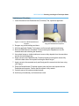
Saw Guide
8.25
9.25
10.25
Clamp Jaw
Assemble the appropriately sized Saw Guide
into the Patella Clamp to create a Saw Guide
Assembly as shown in Figure 21.
Figure 21
42
RESTORIS MCK Planning and Surgical Technique Guide
Align the Saw Guide cutting slot to the medial
side of the patella. Position the handle
approximately parallel to the tibia (Figure 22).
Engage the Saw Guide teeth onto the center
of the patellar articular surface ridge and
allow the wings* to guide orientation onto the
medial and lateral patella facets.
Close the Saw Guide Assembly around the
patella. Apply a slight clamping force,
ensuring that the patellar transition zones
and Saw Guide teeth provide proper
alignment and that the cutting slot is
comfortably accessible to the surgeon’s
dominant hand and the saw. The anterior
side of the patella should be centered in the
Clamp Jaw.
Figure 22
Use the Anterior Cut Reference Guide to
verify that the start and exit of the saw blade
resection is where desired (Figure 23). The
proper planar resection is made when the
cutting slot is aligned with the quadriceps
mechanism attachments and with the medial
and lateral cartilage/bone demarcations.
Figure 23
* For Saw Guides without wings engage the teeth onto the center of the patella articular
surface ridge and apply a slight clamping force.
43
RESTORIS MCK Planning and Surgical Technique Guide
Turn the knob tensioner on the Clamp to
apply a clamping force on the patella. Place
thumb or finger on knob tensioner to prevent
possible unwinding during resection.
Insert a 25 mm x 1.27 mm (.050") saw blade
through the Saw Guide and resect the
articular surface of the patella (Figure 24).
Ensure that the resection is flat and smooth.
Unscrew the knob tensioner and remove the
Saw Guide Assembly from the patella.
Figure 24
Using the Patella Sizing/Drill Guides select
the appropriate size Patella Implant (26, 29,
32, 35, 38 or 41 mm diameter). The optimal
patella size is the largest size that does not
overhang the bone superior-inferiorly.
Assemble the Patella Sizing/Drill Guide into
the Drill Guide Handle to create a Drill Guide
Assembly, such that the selected patella size
is opposite the handle teeth (Figure 25).
In the example shown, the selected 38 mm
size is opposite the handle teeth, and the
41 mm size is assembled to the Drill Guide
Handle.
Figure 25
44
RESTORIS MCK Planning and Surgical Technique Guide
Clamp the Drill Guide Assembly firmly onto
the patella so that the spikes fully engage
and the drill guide sits flat on the bone
surface. For proper patella tracking, the
Patella Sizing/Drill Guide should be aligned
with the former patella ridge (i.e., medialized
on the patella bone). This will lateralize the
remaining patella bone.
Centering the Patella Sizing/Drill
Guide will medialize the remaining
patella bone which can tighten the
lateral quadriceps and increase
the risk of lateral subluxation.
Figure 26
While holding the Drill Guide Assembly firmly
in place, drill the three peg holes using the
Patellar/Tibial Peg Drill making sure the drill
stop collar contacts the top of the Patella
Sizing/Drill Guide (Figure 26).
Remove the Drill Guide Assembly and any
loose material from the patella.
Place the Patella Trial onto the resected
patella. Use the Patella Calipers to reassess
the patella thickness (Figure 27).
If the overall thickness is greater than the
original patella bone thickness, consider
shaving off additional patella bone.
Figure 27
Perform manual range of motion check to
ensure proper patella tracking and patella
transitioning.
Remove the Saw Guide Jaw from the Patella
Clamp and insert the blue Cement Clamp
Body to create a Cement Clamp Assembly
(Figure 28).
Apply cement to the resected patella surface,
drilled peg holes, and Patella Implant while
the cement has a doughy consistency. Place
the Patella component onto the resurfaced
patella.
45
Figure 28
RESTORIS MCK Planning and Surgical Technique Guide
Fully open the jaws of the Cement Clamp
Assembly and align the Cement Clamp Body
onto the articular surface of the Patella
Implant and Clamp Jaw teeth to the anterior
surface of the patella.
Close the Cement Clamp Assembly around
the patella and turn the knob tensioner to
apply an adequate clamping force (Figure
29). Ensure that the Patella Implant fully
seats onto the patella bone.
Remove excess cement as needed.
After the cement has sufficiently cured,
loosen the knob tensioner and remove the
Cement Clamp Assembly.
Figure 29
Perform a manual range of motion check and verification of implant fixation prior to
wound closure.
46
RESTORIS MCK Planning and Surgical Technique Guide
RESTORIS MCK TECHNICAL DATA
Patellofemoral /
Femoral Condyle
Tibial Inlay*
Tibial Onlay
Patella
Tibial Inlay*:
Ultra-high molecular weight
polyethylene (UHMWPE)
per ASTM F648
- GUR 1050, resin type 2
- Compression molded
Onlay Insert:
Ultra-high molecular weight
polyethylene (UHMWPE)
per ASTM F648
- GUR 1050, resin type 2
- Compression molded
Ultra-high molecular weight
polyethylene (UHMWPE)
per ASTM F648
- GUR 1050, resin type 2
- Compression molded
Radiographic Marker:
Titanium wire per ASTM
F67
Onlay Baseplate:
Titanium alloy per ASTM
F136
Cast, heat-treated
- Articular surface:
polished
- Cement-contacting
surface: grit blasted
Machined from stock
material
Onlay Insert:
Machined from stock
material
Tyvek/Mylar inner and
outer pouches
Foil inner pouch
- Prior to sealing,
environmental oxygen
(air) is purged with inert
gas
- Impermeable, preventing
re-entry of oxygen
Tyvek/Mylar outer pouch
Packaging
Manufacturing Process
Material
Cobalt chromium (CoCr)
alloy per ASTM F75
Machined from stock
material
Onlay Baseplate:
Machined from stock
material
- Locking surface: satin
finish
- Cement-contacting
surface: grit blasted
Onlay Insert:
Foil inner pouch
- Prior to sealing,
environmental oxygen
(air) is purged with inert
gas
- Impermeable, preventing
re-entry of oxygen
Tyvek/Mylar outer pouch
Foil inner pouch
- Prior to sealing,
environmental oxygen
(air) is purged with inert
gas
- Impermeable, preventing
re-entry of oxygen
Tyvek/Mylar outer pouch
Shelf Life Sterilization
Onlay Baseplate:
Tyvek/Mylar inner and
outer pouches
Gamma, 2.5 - 4.0 Mrad
5 years
*RESTORIS MCK Inlay component is not approved for use in Australia and New Zealand.
47
RESTORIS MCK Planning and Surgical Technique Guide
Femoral Condyle Technical Data
Size
AP
ML
Condylar
Height
Distal
Thickness
Posterior Peg 1
Thickness Height
Peg 2
Height
Peg
Diameter
Keel
Height
1
42.0
16.0
30.9
4.0
5.8
9.00
11.0
6.5
0.0
2
45.0
17.0
33.1
4.0
6.0
9.75
12.0
6.5
0.0
3
48.0
18.0
35.4
4.0
6.2
10.50
13.0
6.5
0.5
4
51.0
19.0
37.6
4.0
6.4
11.25
14.0
6.5
1.0
5
54.0
20.0
39.9
4.0
6.6
12.00
15.0
6.5
1.5
6
57.0
21.0
42.1
4.0
6.8
12.75
16.0
6.5
2.0
7
60.0
22.0
44.4
4.0
7.0
13.50
17.0
6.5
2.5
8
63.0
23.0
46.6
4.0
7.2
14.25
18.0
6.5
3.0
(All dimensions in mm)
ML
Posterior Thickness
Peg Diameter
Peg 2 Height
Condylar Height
Peg 1 Height
AP
48
RESTORIS MCK Planning and Surgical Technique Guide
Tibial Inlay* Technical Data
Size
AP
ML
Thickness
1
30.0
17.5
6.5
7.5
8.5
2
33.0
19.0
6.5
7.5
8.5
3
36.0
20.5
6.5
7.5
8.5
4
39.0
22.0
6.5
7.5
8.5
5
42.0
23.5
6.5
7.5
8.5
6
45.0
25.0
6.5
7.5
8.5
7
48.0
26.5
6.5
7.5
8.5
(All dimensions in mm)
AP
ML
Thickness
*RESTORIS MCK Inlay component is not approved for use in Australia and New Zealand.
49
RESTORIS MCK Planning and Surgical Technique Guide
Tibial Onlay Technical Data
Size
Baseplate Insert Baseplate/ Peg
AP
AP
Insert ML Height
Peg
Diameter
Peg Angle Keel
(Degrees) Height
Thickness
1
38.0
34.8
21.5
7.0
6.5
30
5.0
8.0
9.0 10.0 12.0
2
41.0
37.5
23.0
7.0
6.5
30
5.0
8.0
9.0 10.0 12.0
3
44.0
40.3
24.5
7.0
6.5
30
5.0
8.0
9.0 10.0 12.0
4
47.0
43.0
26.0
7.0
6.5
30
5.0
8.0
9.0 10.0 12.0
5
50.0
45.8
27.5
8.0
6.5
30
6.0
8.0
9.0 10.0 12.0
6
53.0
48.5
29.0
8.0
6.5
30
6.0
8.0
9.0 10.0 12.0
7
56.0
51.3
30.5
8.0
6.5
30
6.0
8.0
9.0 10.0 12.0
8
59.0
54.0
32.0
8.0
6.5
30
6.0
8.0
9.0 10.0 12.0
(All dimensions in mm unless otherwise noted)
Insert AP
Baseplate/
Insert ML
Baseplate
AP
Thickness
Peg Angle
Peg Height
Peg Diameter
50
Keel Height
RESTORIS MCK Planning and Surgical Technique Guide
Patellofemoral Technical Data
Size
Height
Width
Peg Height
Peg Diameter
2
36.5
33.4
10.0
6.5
3
38.7
35.5
10.5
6.5
4
40.9
37.7
11.0
6.5
5
43.2
39.9
11.5
6.5
6
45.4
42.1
12.0
6.5
7
47.6
44.2
12.5
6.5
8
49.8
46.4
13.0
6.5
(All dimensions are in mm unless otherwise noted)
Peg Height
Height
Width
51
RESTORIS MCK Planning and Surgical Technique Guide
Patella Technical Data
Size
Diameter
Thickness
Radius
Peg Diameter
Peg Length
Peg Circle
Diameter
26
26.0
8.0
26.0
5.5
5.5
15.0
29
29.0
8.5
26.0
5.5
5.5
15.0
32
32.0
9.0
26.0
5.5
5.5
18.0
35
35.0
9.5
26.0
5.5
5.5
18.0
38
38.0
10.0
26.0
5.5
5.5
18.0
41
41.0
10.5
26.0
5.5
5.5
18.0
(All dimensions in mm)
Thickness
Diameter
Radius
Peg Length
Peg Diameter
Peg Circle
Diameter
52
RESTORIS MCK Planning and Surgical Technique Guide
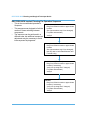
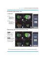
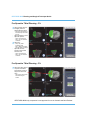
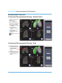
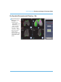
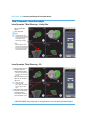
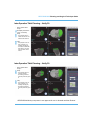
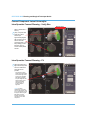
APPENDIX A
RESTORIS MCK Implant Planning (Medial)
•
Appendix A and B describe the sequence of steps required to Pre-Operatively and
Intra-Operatively plan a RESTORIS MCK Bicompartmental (‘RESTORIS MCK BiComp.’)
•
These Appendices can also be used to plan the components of a ‘RESTORIS MCK
PF’ and a ‘RESTORIS MCK UKA’. Although the steps are the same, the screen shot
pictures will not be representative for a single compartment.
•
If only performing an RESTORIS MCK PF or an RESTORIS MCK UKA, it is
recommended to plan for an RESTORIS MCK Bi-Comp to characterize size and fit of
each component.
•
-
For an RESTORIS MCK PF, select the RESTORIS MCK PF from the Implant
System menu. Otherwise, Tibia Registration and Joint Balancing will be required.
-
For an RESTORIS MCK UKA, exit the RESTORIS MCK Bi-Comp and select the
RESTORIS MCK UKA from the Implant System menu. Otherwise,
Bicompartmental Registration will be required. If this is acceptable, remain in
RESTORIS MCK Bi-Comp and ignore the RESTORIS MCK PF.
Each transverse, coronal and sagittal window in the following recommended
technique panel is labeled with a 1, 2, or 3 respectively. The instructions in the left
column are also labeled with a 1, 2, or 3, to correspond to the applicable window
panel.
For each component, required views in each window panel (crosshair)
are set by
choosing the ‘primary’ or applicable ‘verify’ option for each component. The
remaining instructions are only applicable if those views are not altered.
53
RESTORIS MCK Planning and Surgical Technique Guide
RESTORIS MCK Implant Planning Pre-Operative Sequence
•
This is the recommended procedural
Sequence
•
This sequence was designed to limit the
number of times switching between
components
•
The sequence can be performed in a
different order, but additional component
adjustment may be necessary to avoid
intercomponent impingement
Tibial
• Drag from Default location to approximate
location
• Size (repeat above step if size changed)
• Fit (rotate and translate)
• Verify fit
Bicompartmental
• Drag from Default location to approximate
location
• Size (repeat above step if size changed);
this step aids in initial Patellofemoral and
Femoral sizing
Patellofemoral (Trochlear)
• Drag from Default location to approximate
location (if necessary)
• Verify size (re-drag size if changed)
• Fit (rotate and translate)
• Verify fit
Femoral
• Drag from Default location to approximate
location (if necessary)
• Verify size (re-drag size if changed)
• Fit (rotate and translate)
• Verify fit
54
RESTORIS MCK Planning and Surgical Technique Guide
Implant Planning Abbreviations
•
AP – Anterior-Posterior
•
ML – Medial-Lateral
•
SI – Superior-Inferior (same as Proximal-Distal)
•
V/V – Varus-Vargus
•
F/E– Flexion-Extension
•
I/E– Internal-External
•
PFJ – Patellofemoral Joint procedure
•
UKA – Unicondylar Knee Arthroplasty procedure
•
PF – Patellofemoral (Trochlear) component
RESTORIS MCK Tibial Component Pre-Operative Planning: Summary
Onlay: maximize cortical
coverage without overhanging
Align edge with tibial
eminence ridge
Inlay*: maintain offset of 2-3
mm from cortical rim
3 mm proud of bone (Note:
for the Inlay* do not inset
more than 3.5 mm below
cortical bone surface)
Lateral edge of
implant blends with
eminence ridge
Onlay: best match baseplate
perimeter with cortical rim
Inlay*: best match inlay*
perimeter to 2-3 mm cortical rim
offset
Set implant in Primary view and scroll through the slices or use the Verify 1 and Verify 2
preset views to verify planning criteria.
*RESTORIS MCK Inlay component is not approved for use in Australia and New Zealand.
55
RESTORIS MCK Planning and Surgical Technique Guide
RESTORIS MCK Bicompartmental Pre-Operative Planning: Summary
The Bicompartmental planning step is
used to set initial size of the PF (trochlear)
and Femoral Condyle components
• Changing sizes changes the size of both
components
• Adjusting position simultaneously
changes position of both components
Bicompartmental size based on medial AP length
• Anterior: PF is 1 mm proud of bone
• Posterior: Femoral is 2 mm inset or 1 mm proud
Patellofemoral (Trochlear) Pre-Operative Planning: Summary
View:
View:
7 Verify 1
Ensure proximal
medial tip rests
on/in bone surface
2 Primary
View:
3 Primary
Move AP so that
proximal lateral
tip is split midway
by bone
Select largest size that does
not overhang (0-2 mm inset
from medial and lateral ridges)
View:
4 Verify 2
Adjust F/E of Trochlear
component to be 2 mm
proud of trochlear
groove bone
View:
1 Primary
Set PF wings 2 mm
proud of bone
View:
6 Primary
Set Trochlear I/E rotation to
0-4° internal (acceptable for
implant to be recessed into
lateral cortex)
56
Most distal point of
intercondylar groove
Ensure distal tip is
anterior to
Blumensaat’s line
View:
5 Verify 2
RESTORIS MCK Planning and Surgical Technique Guide
RESTORIS MCK Femoral Component Pre-Operative Planning: Summary
Best match Femoral medial edge
to condylar curvature (inset from
medial edge 1-2 mm)
Centralize component on condyle
Set Femoral anterior tip just proud
of bone and below PF wing
Best match sagittal J-curve,
offset from bone ~1 mm
Set implant in Primary view and verify intercomponent gap in Verify 1
57
RESTORIS MCK Planning and Surgical Technique Guide
Tibial Component
Pre-Operative Tibial Planning – Default Position
• Component is imported in
Default location
• Size 5 is Default size
• Select ‘Medial TibiaPrimary’
Crosshair automatically
positioned at implant
center:
1 3.5 mm from top
2 Center of medial peg
3 ML midplane
3D view set to Transverse
(Proximal)
Pre-Operative Tibial Planning – Drag
1 Drag and drop
component into a rough
AP and ML position
3 Drag component to ~3
mm proud
•
Onlay Visual gap
- Gap created to distinguish
between Baseplate &
Insert
- Note: gap created by
removing material from
Insert so Baseplate shown
corresponds to actual
geometry
58
RESTORIS MCK Planning and Surgical Technique Guide
Pre-Operative Tibial Planning – Size
1 Determine Tibial
Component size:
2 Onlay
- Ideal size is largest
component that will not
overhang AP, ML, and not
intrude into tibial
intercondylar eminence
3 Inlay*
- Ideal size is largest
component that is 2-3 mm
from cortical rim and not
intrude into tibial
intercondylar eminence
Tibial Planning – Recommended Positioning Limits
Tibial Onlay
1 5° internal ↔ 5° external
AP: on cortical rim
2 0° varus ↔ 1.5° varus
ML: on cortical rim
3 3° slope ↔ 7° slope
SI: 2.5-3.5 mm proud
Tibial Inlay*
1 5° internal ↔ 5° external
AP: 2-3 mm from cortical rim
2 1° varus ↔ 3° varus
ML: 2-3 mm from cortical rim
3 3° slope ↔ 7° slope
SI: 2.5-3.5 mm proud
*RESTORIS MCK Inlay component is not approved for use in Australia and New Zealand.
59
RESTORIS MCK Planning and Surgical Technique Guide
Pre-Operative Tibial Planning – Fit
3 Adjust posterior slope to
be slightly less than
patient tibial bone slope
- Removal of meniscus and
excessive slope can stress
the ACL
•
•
Adjust proudness to 3 mm
Adjust AP position:
- Onlay: avoid overhang
- Inlay*: 2-3 mm inset from
cortical rim
2 Adjust V/V:
- Onlay: stay within
positioning limits
- Inlay*: adjust to be slightly
less than tibial varus slope
•
Adjust ML to avoid
intrusion into the tibial
eminence and:
- Onlay: avoid overhang
- Inlay*: 2-3 mm inset from
cortical rim
Pre-Operative Tibial Planning – Fit
1 Adjust I/E to align edge of
component with tibial
intercondylar eminence
edge and to avoid PCL
notch
{
- Note: ignore anterior bone
when assessing I/E
rotation
*RESTORIS MCK Inlay component is not approved for use in Australia and New Zealand.
60
RESTORIS MCK Planning and Surgical Technique Guide
Pre-Operative Tibial Planning – Verify Fit
•
Select ‘Medial TibiaVerify 1’
3 Re-adjust proudness to
3 mm, if necessary
2 Onlay
3 - Verify implant rests on
cortical rim and does not
interfere with eminence
2 Inlay*
3 - Verify implant is 2-3 mm
from cortical rim (not
including osteophytes)
- To maintain subchondral
bone plate, do not inset
≥3.5 mm below cortical
surface
•
Note: some bone might
be proud at anterior tip
Pre-Operative Tibial Planning – Verify Fit
•
Select ‘Medial TibiaVerify 2’
2 Onlay
3 - Verify implant does not
overhang AP & ML
- Scroll through slices as
necessary to ensure proper
fit
2 Inlay*
3 - Verify implant is 2-3 mm
from cortical rim (not
including osteophytes)
- Scroll through slices as
necessary to ensure proper
fit
*RESTORIS MCK Inlay component is not approved for use in Australia and New Zealand.
61
RESTORIS MCK Planning and Surgical Technique Guide
Bicompartmental Component
Pre-Operative Bicompartmental Planning – Default Position
• Component is imported in
Default location
• Size 5 is Default size
• Select ‘Bi-Comp (medium)’
Crosshair automatically
positioned through largest
AP section:
1 Largest AP length
(Upside-down ‘Frowny
Face’)
2 Patella transition (distal
tongue of PF)
3 ML center of PF (‘Fish
Hook’)
3D view set to Transverse
(Distal)
Pre-Operative Bicompartmental Planning – Drag
2 Drag Bicompartmental
so that medial side of PF
is approximately 1 mm
proud of red bone
surface
3 Drag Bicompartmental
so that PF tongue is split
midway by red bone
surface
62
RESTORIS MCK Planning and Surgical Technique Guide
Pre-Operative Bicompartmental Planning – Size
•
•
1 Bicompartmental sizing:
Based on AP medial
bone length
Ideal Bicomp size:
- Anterior medial PF:1 mm
proud of bone
- Posterior Condyle:2 mm
inset or 1 mm proud
•
If Posterior Condyle
>2 mm inset → upsize
>1 mm proud → downsize
•
Note: some internal
rotation might be
required to assess size
•
If size changed, re-drag
component to correct
location
63
RESTORIS MCK Planning and Surgical Technique Guide
Patellofemoral (Trochlear) Component
Pre-Operative Patellofemoral Planning – Default Position
• Size and position are
based on Bicompartmental
planning
• Select ‘PF-Primary’
Crosshair automatically
positioned:
1 Widest section of PF
(‘Mad Face’)
2 Patella transition (distal
tongue of PF)
3 Proximal lateral tip (solid
lateral sphere)
3D view set to Transverse
(Distal)
Pre-Operative Patellofemoral Planning – Verify Size
1 Verify PF size:
- Ideal PF size is the largest
that does not overhang
the bone ridges (no more
than 2 mm inset on either
side) ensuring it does not
interfere with the ACL (not
including osteophytes)
- If size changed, re-select
‘PF-Primary’ and move to
correct location
64
RESTORIS MCK Planning and Surgical Technique Guide
Patellofemoral (Trochlear) - Recommended Positioning Limits
Patellofemoral (Trochlear)
1 4° internal ↔ 0° external
AP: ~2 mm proud of bone at
the trochlear groove
NOTE: Every degree of
internal rotation medializes
the trochlear groove
~0.5 mm and raises the
patella jump height ~0.3 mm
2 3° varus ↔ 2° valgus
ML: centered on notch
NOTE: Every degree of V/V
rotation translates the
trochlear groove entrance by
~0.6 mm
2 5° flexion ↔ 5° extension
SI: bone line splits
implant
Pre-Operative Patellofemoral Planning – Fit
•
Select ‘PF-Primary’
1 Fit anterior shape:
- If desired, adjust I/E to
roughly match the
anatomy. If Internal
rotation is used ensure
that the lateral PF ridge is
not proud of bone.
- For lateral dysplasia, try to
maintain 1 mm of lateral
proudness without going
into external rotation
3 Fit proximal lateral tip:
- Move AP so that the
proximal lateral tip of PF is
split midway by the bone
surface
65
RESTORIS MCK Planning and Surgical Technique Guide
Pre-Operative Patellofemoral Planning – Fit
•
Select ‘PF-Primary’
2 Fit distal tongue:
- Adjust V/V and ML to best
match patellar transition
zones shape to bone
shape
- Adjust SI so patellar
transition zones are 2 mm
proud of bone surface
Pre-Operative Patellofemoral Planning – Verify Fit
•
Select ‘PF-Verify 2’
3 Verify ACL notch:
- Adjust F/E so that the
trochlear groove of the
implant is ~2 mm proud of
bone
- Verify that distal tongue
does not violate the
intercondylar notch and
cause ACL impingement.
PF distal tip should be
anterior to Blumensaat’s
line
66
RESTORIS MCK Planning and Surgical Technique Guide
Pre-Operative Patellofemoral Planning – Verify Fit
•
Select ‘PF-Verify 1’
3 Verify fit of proximal
medial tip:
- Verify medial tip of PF
rests in or on red bone
surface (does not need to
be split by red bone
surface)
- If the medial tip rests off
bone, translate PF
posterior to rest on bone
surface
67
RESTORIS MCK Planning and Surgical Technique Guide
Femoral Component
Pre-Operative Femoral Planning – Default Position
• Size and position are
based on Bicompartmental
planning
• Select ‘Medial FemurPrimary’
Crosshair automatically
positioned at flexion facet
center (near posterior peg
tip)
3D view set to Transverse
(Distal)
Femoral Planning – Recommended Positioning Limits
Femoral Condyle
1 5° internal ↔ 5° external
AP: 1 mm proud of bone
2 3° varus ↔ 3° valgus
ML: centered on condyle
3 5° flexion ↔ 5° extension
SI: 1 mm proud of bone
68
RESTORIS MCK Planning and Surgical Technique Guide
Pre-Operative Femoral Planning – Fit
1 Match medial condylar
curvature of bone:
- Adjust I/E to match
condylar curvature
(excluding osteophytes)
- Adjust ML to centralize
condyle and to be 12 mm inset from medial
edge
2 Adjust V/V to match PF
component
- Do not try to match
component shape with
arthritic bone shape
using V/V
Pre-Operative Femoral Planning – Fit
3 Match ‘J-curve’:
- Adjust AP, SI, & F/E to
match bone J-curve and
to be 1 mm proud of bone
- Adjust F/E as necessary
to ensure anterior tip is not
inset into bone and not
protruding through PF
transition zone
69
RESTORIS MCK Planning and Surgical Technique Guide
Pre-Operative Femoral Planning – Verify Fit
•
Select ‘Medial Femur –
Verify 1’
2 Verify intercomponent
gap is ≥3 mm and the
Femoral does not
protrude through patellar
transition zone
3 Verify intercomponent
gap is ≥3 mm and the
Femoral does not
protrude through patellar
transition zone
- Anterior tip of Femoral
should be slightly proud of
bone
- For a UKA, the Femoral
should not be proud of the
cartilage
70
RESTORIS MCK Planning and Surgical Technique Guide
APPENDIX B
RESTORIS MCK Implant Planning Intra-Operative Sequence
•
Verify the Pre-Operative plan prior to
Intra-Operative planning
•
The Bicompartmental step in PreOperative planning is only used to
establish initial component sizing,
therefore is not needed for IntraOperative planning
Joint Balancing (Pose Capture)
• Remove osteophytes and apply
moment at ankle
• 5° - 10° (Extension gap balancing)
• 45° (Mid flexion gap balancing)
• 95° (Flexion gap balancing)
• 100° - 120° (Maximum flexion)
Tibial
• Verify size and fit using same steps as
Pre-Operative Planning
Patellofemoral (Trochlear)
• Map bone and cartilage
• Adjust placement and best match
proximal lateral tip, trochlear groove,
and patella transition
• Verify fit
Femoral
• Map cartilage at anterior tip
• Best match to Tibial tracking point
• Adjust placement to desired gap
balancing graph profile
• Verify fit
71
RESTORIS MCK Planning and Surgical Technique Guide
Intra-Operative Planning
Joint Balancing (Pose Capture)
•
Prior to Joint Balancing (Pose Capture)
- Ensure osteophytes have been removed
•
During Joint Balancing (Pose Capture)
- Ensure VALGUS moment is applied to tibia at each pose
•
Recommended Pose Captures for Joint Balancing*
- 5˚-10˚ (Extension gap balancing)
- 45˚ (Mid-flexion gap balancing)
- 90˚ (Flexion gap balancing)
- 100˚-120˚ (Maximum flexion)
* Joint balancing not required for RESTORIS MCK PFJ procedure because the tibia is not
registered.
Intra-Operative Joint Balancing (Pose Capture)
• Obtain pose captures for
joint balancing at
approximately
- 5° - 10° knee flexion
(Extension gap balancing)
72
RESTORIS MCK Planning and Surgical Technique Guide
Intra-Operative Joint Balancing (Pose Capture)
• Obtain pose captures for
joint balancing at
approximately
- 45° knee flexion (Mid-flexion
gap balancing)
Intra-Operative Joint Balancing (Pose Capture)
• Obtain pose captures for
joint balancing at
approximately
- 90° knee flexion (Flexion
gap balancing)
73
RESTORIS MCK Planning and Surgical Technique Guide
Intra-Operative Joint Balancing (Pose Capture)
• Obtain pose captures for
joint balancing at
approximately
- 100° - 120° (Maximum
flexion)
74
RESTORIS MCK Planning and Surgical Technique Guide
RESTORIS MCK Tibial Component Intra-Operative Planning: Summary
Onlay: maximize cortical
coverage without overhanging
Align edge with tibial
eminence ridge
Inlay*: maintain offset of 2-3
mm from cortical rim
3 mm proud of bone (Note:
for the Inlay* do not inset
more than 3.5 mm below
cortical bone surface)
Lateral edge of
implant blends with
eminence ridge
Onlay: best match baseplate
perimeter with cortical rim
Inlay*: best match inlay*
perimeter to 2-3 mm cortical rim
offset
Set implant in Primary view and scroll through the slices or use the Verify 1 and Verify 2
preset views to verify planning criteria.
Patellofemoral (Trochlear) Intra-Operative Cartilage Mapping
2
1
Map 2 points at
medial and
lateral superior
edge
3
Map 5 cartilage points
along the deepest point
of the trochlear groove
(most anterior to most
distal)
Map 3 cartilage
points along each
of the medial and
lateral transition
edges
*RESTORIS MCK Inlay component is not approved for use in Australia and New Zealand.
75
RESTORIS MCK Planning and Surgical Technique Guide
Patellofemoral (Trochlear) Intra-Operative Planning Summary
View:
5 Verify 1
Ensure medial
tip rests on/in
bone surface
View:
View:
1 Primary
2 Verify 2
Adjust F/E of Trochlear
component to best
match (±1 mm) 3 most
anterior trochlear
groove points*
Move AP to ensure
implant is split midway
by bone/mapped
surface
View:
4 Primary
Move Trochlear V/V and S/I
to best match (±1 mm)
lateral cartilage transition
region
*Note: if the mapped
points lie on arthritic bone
and not cartilage, adjust
F/E to be ~2 mm proud of
bone surface
Ensure distal tip is anterior to
Blumensaat’s line
View:
3 Verify 2
RESTORIS MCK Femoral Component Intra-Operative Planning: Summary
Best match Femoral medial edge
to condylar curvature (inset from
medial edge 1-2 mm)
Best match Femoral High Point
Groove to Tibial trace points from
Joint Balancing (Pose Capture)
Set Femoral anterior tip just
proud of bone, below PF wing,
and/or slightly inset to cartilage
Adjust Femoral to obtain
desired joint balancing gap
(0-1.5 mm looseness)
76
RESTORIS MCK Planning and Surgical Technique Guide
Intra-Operative Planning
Extension
Gap
Adjust femoral SI to
set desired
extension gap
Flexion Gap
Adjust femoral AP
to set desired
flexion gap
77
RESTORIS MCK Planning and Surgical Technique Guide
Mid - Flexion
Flex the implant
slightly to increase
the gap in mid
flexion
Extend the implant
slightly to decrease
the gap in mid
flexion
Quick Fit
Overview
Quick Fit optimizes the placement of the Femoral Condyle component in the sagittal plane
(anterior-posterior translation, superior-inferior translation, and optionally flexionextension rotation) using the inputs from the captured poses from Joint Balancing and the
desired gap values entered in Gap Settings or Surgeon Preferences.
Quick Fit is only available when the Femoral Condyle plan is active.
Upon clicking Quick Fit, the Femoral Condyle placement and graph are automatically
updated.
Desired Gap Settings
Desired gap values for extension, mid-flexion, and flexion can be set in Gap Settings or
Surgeon Preferences. The gap values for each flexion range can vary from -5 mm to
+5 mm in 0.5 mm increments. Quick Fit will attempt to achieve all desired gap setting
values within their tolerance settings. The tolerance settings for extension, mid-flexion, and
flexion are ±0.25 mm, ±1 mm, and ±0.25 mm, respectively. For example, if the desired
extension gap is set to 1 mm, Quick Fit may provide an output where the extension gap is
0.75-1.25 mm.
78
RESTORIS MCK Planning and Surgical Technique Guide
Since extension and flexion gaps are of primary concern to surgeons, these
tolerances were set narrower than the mid-flexion tolerance.
If Quick Fit cannot find a solution that meets all the desired gap values set by the
user, a warning will be displayed indicating that the gap value for the indicated pose
is outside the desired gap range.
Captured Pose Ranges
The extension and flexion pose target angles can be set to a value within 5-25° and
80-150° of flexion, respectively. The extension and flexion pose angle ranges are defined
as ±5° of the target value, so the possible extension range is 0-30° flexion and the possible
flexion range is 75-155° flexion. If multiple poses are taken within the defined range, only
the pose closest to the target angle will be included in Quick Fit. The mid-flexion pose
range can be within 31-74°of flexion. All poses taken within the mid-flexion range will be
included in Quick Fit.
If no poses are taken within the defined ranges, clicking Quick Fit will result in a
warning instructing the user to take a pose within the indicated range.
Only poses captured within the specified pose ranges are used in the Quick Fit
calculations.
Anterior Tip Fit
Literature suggests that femur cartilage thickness near the Femoral Condyle anterior tip is
approximately 2 mm, but each patient’s cartilage thickness is unique and could vary from
1-3 mm thick. It is recommended that the surgeon maps cartilage near the anterior tip to
ensure that the Femoral Condyle component does not impinge with the patella during knee
flexion. The distance from the anterior tip to the bone is always displayed in the information
box even if cartilage is not mapped. Quick Fit will attempt to place the anterior tip of the
Femoral Condyle component between 1 mm and 3 mm proud of the bone. If the maximum
tip distance is greater than 2 mm, the information box will display a yellow message
advising the surgeon to map cartilage along the anterior tip. If proud of the cartilage, the
surgeon should make manual adjustments until the anterior tip is flush with or recessed
below cartilage. Peer-reviewed literature suggests that recessing the anterior tip does not
affect UKA outcomes [1,2]. However, additional warnings will be displayed if the tip is
excessively recessed (approximately 5 mm deep) or excessively proud (>3 mm proud).
79
RESTORIS MCK Planning and Surgical Technique Guide
The surgeon then must exercise good medical judgment if changes need to be made to
the implant plan.
References:
1. Simultaneous In-vitro Measurement of Patellofemoral Kinematics and Forces
Following Oxford Medial Unicompartmental Knee Arthroplasty. A Price, PT
Oppold, DW Murray, AB Zavatsky. Journal of Bone and Joint Surgery [Br] 2006;
88-B: 1591-1595. Price et al.In vitro measurement of PF kinematics and forces
following Oxford medial UKA.JBJS-Br. 2006.
2. The influence of the presence and severity of pre-existing patellofemoral
degenerative changes on the outcome of the Oxford medial unicompartmental
knee replacement. Beard DJ, Pandit H, Gill HS, Hollinghurst D, Dodd CA, Murray
DW. Journal of Bone and Joint Surgery [BR] 2007; Dec; 89(12):1597-601.
Since each patient has a unique cartilage thickness near the anterior tip of the
Femoral Condyle component, it is recommended that the surgeon maps the cartilage
surface near the anterior tip to avoid patella impingement. If the anterior tip is proud
of the cartilage after Quick Fit, the surgeon can manually make adjustments to the
implant plan to achieve the desired placement.
This feature does not replace the need for cartilage mapping.
Mid-Flexion and Femoral Condyle Rotation
When Mid-Flexion is checked in the Gap Settings, the Femoral Condyle component flexion
rotation angle will be adjusted to best match the desired mid-flexion gap setting, while
staying within the recommended positioning limits (5° extension to 5° flexion rotation). If
the user prefers a different flexion rotation angle or one outside the recommended
positioning limits, then Mid-Flexion can be unchecked and Quick Fit will only translate the
Femoral Condyle component to meet the desired extension and flexion gap settings.
Quick Fit provides a quick and easy suggested position of the Femoral Condyle
component based on the inputs of the surgeon (poses and gap settings for a given
Tibial component plan). The surgeon should fully consider all gap values for all poses
even if certain poses are not used by Quick Fit. For example, if the target flexion pose
angle is 90° and poses were taken at 93° and 115° flexion, only the pose at 93° will
be used by Quick Fit, but the gap value at 115° should be considered before
accepting the final plan. Final acceptance of the implant plan must still be made by
the surgeon.
80
RESTORIS MCK Planning and Surgical Technique Guide
Quick Fit does not adjust Femoral Condyle medial-lateral translation, varus-valgus
rotation, and internal-external rotation. Therefore, the surgeon still must manually
adjust these settings for proper placement. Quick Fit does not adjust Tibial
component placement.
If the Tibial or Femoral Condyle component position or size is changed after Quick
Fit has been performed, Quick Fit will need to be executed again.
As with any optimization, the output is only as good as the input. If the ligaments are
not properly tensioned and/or the limb is not properly aligned during Joint Balancing
pose captures, Quick Fit cannot be expected to provide a proper clinical outcome.
Kinematic Analysis
Overview
During either component trial evaluation or final implant evaluation, the Kinematic Analysis
page provides the surgeon the ability to quantify post-resection limb alignment in
extension, joint gaps, and kinematic range of motion. This page also enables the user to
compare post-resection limb alignment and joint gaps to pre-resection values. This page
is available, but not required for completing a MAKOplasty.
Capture Contact
To enable the features in Kinematic Analysis, contact poses must first be taken. Capture
contact poses from full extension to full flexion to record full range of motion. Ensure that
the trials/implants are in continuous contact with each other throughout range of motion.
When capturing contact poses, apply neutral internal/external rotation torque on the tibia
and let the soft tissue guide its natural motion.
Contact poses are necessary to zero out the errors due to bone registration, over/
under resection of bone, and due to introduction of cement after implantation.
The trial or implant insert thickness used during Capture Contact must be the same
as the Poly thickness selected in the drop down menu. If they are not, errors in the
gap values may result.
The tibial and femoral arrays should not be moved after resection in order for the
Kinematic Analysis page to work for both trialing and implantation options.
81
RESTORIS MCK Planning and Surgical Technique Guide
Gap Graph
Selecting the graph icon displays the Gap Graph at the top of the page. To view the preresection gap values, toggle on Pre-Resection. The Gap Graph can display gap values for
all poses taken during pre-resection and post-resection for comparison.
Live Kinematic Values
After contact poses are collected, live kinematic values are displayed in both sagittal and
coronal planes.
Flexion Angle. The live flexion angle of the knee is displayed in the sagittal window. When
Pre-Resection is toggled on, the sagittal kinematic window will display blue dots on the
flexion dial, indicating the flexion angles where pre-resection poses were taken. When the
knee is within ±5° flexion of the pre-resection pose, pre-resection values will be displayed
in the coronal window. Outside the ±5° flexion range of pre-resection, the value boxes will
display N/A.
Tibiofemoral Varus/Valgus. The coronal window displays three values of tibiofemoral
varus/valgus. The ‘Contact’ values are the angles recorded during ‘Capture Contact’. The
‘Varus’ (or Valgus) value is the live varus/valgus angle of the knee in the current pose.
When Pre-Resection is toggled on and the knee is within ±5° flexion of the pre-resection
pose, the ‘Pre-resection’ value recorded during Joint Balancing is displayed. The live
varus/valgus angle should only be compared to the Pre-resection angle when the same
varus/valgus moment is applied to the knee as during pre-resection Joint Balancing.
Internal/External Rotation. The coronal kinematic window displays the relative difference
(delta) of the current internal/external rotation (axial rotation) to that taken during the
contact pose.When Pre-Resection is toggled on and the knee is within ±5° flexion of the
pre-resection pose, a blue dot will appear on the delta axial rotation dial indicating the axial
rotation difference between the contact pose and pre-resection pose. For best comparison
to pre-resection values, the blue dot should be within the delta window.
Capture Gap
The ‘Gap’ value is the joint space between the Femoral and Tibial components. This value
should read zero when no moment is applied to the leg. To view the joint gap value at any
flexion angle, apply the same varus/valgus moment that was applied during Joint
Balancing. Visually confirm that the actual gap seen matches that displayed in the gap
value box.When Pre-Resection is toggled on and the knee is within ±5° flexion of the preresection pose, the ‘Pre-resection’ gap value recorded during Joint Balancing is displayed.
Click ‘Capture Gap’ to record the gap for a given flexion angle in the bar graph. To compare
post-resection gaps to pre-resection gaps, it is best to obtain joint gaps within ±5° flexion
of the pre-resection poses. However, there is no limitation on how many post-resection
82
RESTORIS MCK Planning and Surgical Technique Guide
gaps can be obtained, but flexion angles are limited to those collected during contact
poses.
For most accurate results, capture the gap when the knee is within ±5° of axial rotation of
the contact pose. Adjust the axial rotation of the knee until the rotation bar is within the ±5°
delta window. The delta window will turn to a different color when within the proper range.
If the gap values are larger than desired, changing the Poly thickness in the drop down
menu after ‘Capture Contact’ can be used to predict the effect of a thicker trial/implant.
The gap value should not be negative unless axial rotation was excessively outside
that taken during pre-resection or if the trials/implants were not touching during
contact pose captures.
The post-resection gap may be less or greater than the pre-resection value if the
varus/valgus moment is not the same as in pre-resection, if there are joint changes
due to bone resection such as release of capsular adhesions and/or additional
osteophyte removal, or if axial rotation is outside the axial rotation delta window.
It is recommended that the trial or implant insert thickness used during joint gap
evaluation be the same as the poly thickness selected in the drop down menu. If they
are not, errors in the values may result.
If the trial or implant insert thickness is changed, it is recommended that you delete
the captured gap poses and recapture new contact and gap poses.
83
RESTORIS MCK Planning and Surgical Technique Guide
Patellofemoral Component
Intra-Operative Patellofemoral Planning
• Select ‘PF-Primary’
• Map Cartilage / Bone
- Map 2 bone points on the
proximal edge near the
medial and lateral violet tip
points
- Edge points will ensure that
the implant is placed midway
through bone surface
Intra-Operative Patellofemoral Planning
• Map Cartilage / Bone
• Map 5 cartilage points
along the deepest point of
the trochlear groove (most
anterior to most distal)
84
RESTORIS MCK Planning and Surgical Technique Guide
Intra-Operative Patellofemoral Planning
• Map Cartilage / Bone
- Map a minimum of 3
cartilage points on each of
the lateral and medial PF
patellar transition zone
edges
Selecting edge points next to
the 2 violet points and 1 edge
point in between will provide
ideal spacing
NOTE: These 13 are the
minimum recommended points
to be mapped, more points can
be collected as needed to
ensure a successful implant
plan
Intra-Operative Patellofemoral Planning
3 Adjust AP so that PF is
split midway by mapped
surface
85
RESTORIS MCK Planning and Surgical Technique Guide
Intra-Operative Patellofemoral Planning
•
Select ‘PF-Verify 2’
3 Set the crosshair at the
proximal implant in the
Sagittal view
•
Adjust F/E of Trochlear
component to best
match (± 1 mm) the 3
most anterior trochlear
groove points
- NOTE: if the mapped
points lie on arthritic bone
and not cartilage, adjust F/
E to be ~2 mm proud of
bone surface
•
Verify ACL notch
- PF distal tip should be
anterior to Blumensaat’s
line
Intra-Operative Patellofemoral Planning
•
Select ‘PF-Primary’
3 Adjust V/V and SI to best
match patellar transition
zones to mapped lateral
cartilage
- If lateral cartilage is
thicker than medial
cartilage, match lateral
cartilage
- If medial cartilage is
thicker than lateral
cartilage, match PF to be
halfway between medial
and lateral cartilage
86
RESTORIS MCK Planning and Surgical Technique Guide
Intra-Operative Patellofemoral Planning
•
Select ‘PF-Verify 1’
3 Verify that the PF rests
on or in mapped surface
- If the mapped surface is
inside the PF, no action is
required
- If PF does not contact
mapped surface, translate
posterior until PF contacts
mapped surface
- Note: Moving the PF in
this view will change the fit
in the previous step
87
RESTORIS MCK Planning and Surgical Technique Guide
Femoral Component
Intra-Operative Femoral Planning – Verify Size
•
Select ‘Medial Femur –
Primary’
3 Verify intercomponent
gap ≥3 mm and Femoral
has full posterior condyle
coverage
•
Map cartilage points in
transition region to
ensure smooth patella
handoff
Intra-Operative Femoral Planning – Fit
1 Adjust I/E and/or ML to
align Femoral High Point
Groove to Tibial tracking
points as best as
possible
- This will aid in central
Tibial component
- The Femoral High Point
Groove is the probable
tibial tracking pathway
Note: For better
visualization, set Implant
View to ‘Tibia – Primary’ and
turn on ‘All Implants’ to cycle
through the flexion angles
and watch the actual
tracking of the femoral
component on the tibia
component
88
RESTORIS MCK Planning and Surgical Technique Guide
Intra-Operative Femoral Planning – Fit
2 Adjust V/V to match PF
component or to better
match Tibial tracking
points, but stay within
positioning limits
3 Adjust F/E, AP, and SI to
obtain desired joint
balancing gap
- Goal: 0-1.5 mm looseness
in graph
- If mid-flexion gap is tight,
flex Femoral
- If mid-flexion gap is loose,
extend Femoral
Note: If Quick Fit is enabled,
use Quick Fit at this time.
Intra-Operative Femoral Planning – Verify Fit
•
Select ‘Medial Femur –
Verify 1’
2 Verify intercomponent
gap is ≥3 mm and the
Femoral does not
protrude through patellar
transition zone
3 Verify intercomponent
gap is ≥3 mm and the
Femoral does not
protrude through patellar
transition zone
- Anterior tip of Femoral
component should be
slightly proud of bone
- For a UKA, the Femoral
component should not be
proud of the mapped
cartilage surface
89
RESTORIS MCK Planning and Surgical Technique Guide
APPENDIX C
RESTORIS MCK lateral Unicondylar Implant Planning Pre-Operative
Sequence
•
This is the recommended procedural
sequence
•
This sequence was designed to limit the
number of times switching between
components
•
The sequence can be performed in a
different order, but additional component
adjustment may be necessary
Tibial
• Drag from Default location to approximate
location
• Size (repeat above step if size changed)
• Fit (rotate and translate)
• Verify fit
Femoral
• Drag from Default location to approximate
location (if necessary)
• Verify size (re-drag if size changed)
• Fit (rotate and translate)
• Verify fit
90
RESTORIS MCK Planning and Surgical Technique Guide
RESTORIS MCK Tibial Component Pre-Operative Planning: Summary
Onlay: maximize cortical
coverage without overhanging
3 mm proud of bone (note:
for the Inlay* do not inset
more than 3.5 mm below
cortical bone surface)
Slightly internally rotated
with respect to tibial
eminence ridge
Inlay*: maintain offset of 2-3
mm from cortical rim
Medial edge does not
intrude into tibial
eminence
Onlay: best match baseplate
perimeter with cortical rim
Inlay*: best match inlay*
perimeter to 2-3 mm cortical
rim offset
RESTORIS MCK Femoral Component Pre-Operative: Summary
Set Femoral anterior tip just
proud of bone, slightly inset to
cartilage
Size Femoral by aligning to
meniscal notch
Best match Femoral lateral edge
to condylar curvature (inset from
lateral edge ~1 mm)
Best match sagittal J-curve,
offset from bone ~1 mm
Centralize component on condyle
*RESTORIS MCK Inlay component is not approved for use in Australia and New Zealand.
91
RESTORIS MCK Planning and Surgical Technique Guide
Tibial Component: Lateral Unicondylar
Pre-Operative Tibial Planning – Default Position
• Component is imported in
Default location
• Size 5 is Default size
• Select ‘Lateral TibiaPrimary’
Crosshair automatically
positioned at implant
center:
1 3.5 mm from top
2 Center of medial peg
3 ML midplane
3D view set to Transverse
(Proximal)
Pre-Operative Tibial Planning – Drag
1 Drag and drop
component into a rough
AP and ML position
3 Drag component to
~3 mm proud
•
Onlay visual gap:
- Gap created to distinguish
between Baseplate &
Insert
- Note: gap created by
removing material from
Insert so Baseplate shown
corresponds to actual
geometry
92
RESTORIS MCK Planning and Surgical Technique Guide
Pre-Operative Tibial Planning – Size
1 Determine Tibial
2 Component size:
3
• Onlay
- Ideal size is largest
component that will not
overhang AP, ML, and not
intrude into tibial
intercondylar eminence
•
Inlay*
- Ideal size is largest
component that is 2-3 mm
from cortical rim and not
intrude into tibial
intercondylar eminence
Tibial Planning – Recommended Positioning Limits
Tibial Onlay
1 10° internal ↔ 5° external
AP: on cortical rim
2 0° valgus ↔ 1.5° valgus
ML: on cortical rim
3 0° slope ↔ 7° slope
SI: 2.5-3.5 mm proud
Tibial Inlay*
1 10° internal ↔ 5° external
AP: 2-3 mm from cortical rim
2 1° valgus ↔ 3° valgus
ML: 2-3 mm from cortical rim
3 0° slope ↔ 7° slope
SI: 2.5-3.5 mm proud
*RESTORIS MCK Inlay component is not approved for use in Australia and New Zealand.
93
RESTORIS MCK Planning and Surgical Technique Guide
Pre-Operative Tibial Planning – Fit
3 Adjust posterior slope to
be slightly less than
patient tibial bone slope
- Removal of meniscus and
excessive slope can stress
the ACL
•
•
Adjust proudness to 3 mm
Adjust AP position:
- Onlay: avoid overhang
- Inlay*: 2-3 mm inset from
cortical rim
2 Adjust V/V:
- Onlay: stay within
positioning limits
- Inlay*: adjust to be slightly
less than tibial valgus slope
•
Adjust ML to avoid
intrusion into the tibial
eminence and:
- Onlay: avoid overhang
- Inlay*: 2-3 mm inset from
cortical rim
Pre-Operative Tibial Planning – Fit
1 Rotate so edge of
component is slightly
internally rotated with
tibial intercondylar
eminence edge and to
avoid PCL notch
- Note: ignore anterior bone
when assessing I/E
rotation
*RESTORIS MCK Inlay component is not approved for use in Australia and New Zealand.
94
RESTORIS MCK Planning and Surgical Technique Guide
Pre-Operative Tibial Planning – Verify Fit
•
Select ‘Lateral TibiaVerify 1’
3 Re-adjust proudness to
3 mm, if necessary
2 Onlay
3 - Verify implant rests on
cortical rim and does not
interfere with eminence
2 Inlay*
3 - Verify implant is 2-3 mm
from cortical rim (not
including osteophytes)
- To maintain subchondral
bone plate, do not inset
≥3.5 mm below cortical
surface
•
Note: some bone might
be proud at anterior tip
Pre-Operative Tibial Planning – Verify Fit
•
Select ‘Lateral TibiaVerify 2’
2 Onlay
3 - Verify implant does not
overhang AP & ML
- Scroll through slices as
necessary to ensure proper
fit
2 Inlay*
3 - Verify implant is 2-3 mm
from cortical rim (not
including osteophytes)
- Scroll through slices as
necessary to ensure proper
fit
*RESTORIS MCK Inlay component is not approved for use in Australia and New Zealand.
95
RESTORIS MCK Planning and Surgical Technique Guide
Femoral Component: Lateral Unicondylar
Pre-Operative Femoral Planning – Default Position
• Select ‘Lateral FemurPrimary’
Crosshair automatically
positioned at flexion facet
center (near posterior peg
tip)
3D view set to Transverse
(Distal)
• Component is imported in
Default location
• Size 5 is Default size
Pre-Operative Femoral Planning – Drag
1 Drag and drop
component into a rough
position on the lateral
condyle
3 Drag component to
~1 mm proud
96
RESTORIS MCK Planning and Surgical Technique Guide
Pre-Operative Femoral Planning – Size
3 Determine femoral
component size
•
Ideal size is when
anterior tip is
approximately aligned
with meniscal notch in
3D view and best
matches femoral
J-curve
Femoral Planning – Recommended Positioning Limits
Femoral Condyle
1 5° internal ↔ 5° external
AP: 1 mm proud of bone
2 3° varus ↔ 3° valgus
ML: centered on condyle
3 5° flexion ↔ 5° extension
SI: 1 mm proud of bone
97
Meniscal Notch
RESTORIS MCK Planning and Surgical Technique Guide
Pre-Operative Femoral Planning – Fit
1 Match lateral condylar
curvature of bone:
- Adjust I/E to match
condylar curvature
(excluding osteophytes)
- Adjust ML to centralize
condyle and to be almost
1 mm inset from lateral
edge
2 Adjust V/V, if necessary
- Do not try to match
component shape with
arthritic bone shape using
V/V
- Note: Some valgus may
be necessary to follow
posterior condylar
curvature
Pre-Operative Femoral Planning – Fit
3 Match ‘J-curve’:
- Adjust AP, SI, & F/E to
match bone J-curve and
to be 1 mm proud of bone
- Adjust F/E as necessary
to ensure anterior tip is
slightly inset into bone
- Excessive flexion will
make implantation difficult
98
RESTORIS MCK Planning and Surgical Technique Guide
Pre-Operative Femoral Planning – Verify Fit
• Select ‘Lateral Femur –
Verify 1’
2
3
-
Anterior tip of femoral
component should not
be proud of the
cartilage (map a
cartilage point intra-op,
if necessary)
Excessive anterior
recess or proudness
could cause patella
tracking problems
99
RESTORIS MCK Planning and Surgical Technique Guide
RESTORIS MCK Lateral Unicondylar Implant Planning Intra-Operative
Sequence
Verify the Pre-Operative plan prior to Intra-Operative planning
Joint Balancing (Pose Capture)
• Remove osteophytes and apply moment
at ankle
5° - 10° (Extension gap balancing)
45° (Mid flexion gap balancing)
95° (Flexion gap balancing)
100° - 120° (Maximum flexion)
Tibial
• Verify size and fit using same steps as
Pre-Op Planning
Femoral
• Map cartilage at anterior tip
• Best match to Tibial tracking point
• Adjust placement to desired gap
balancing graph profile
• Verify fit
Joint Balancing (Pose Capture)
•
Prior to Joint Balancing (Pose Capture)
-
•
During Joint Balancing (Pose Capture)
-
•
Ensure osteophytes have been removed
Ensure VARUS moment is applied to tibia at each pose
Recommended Pose Captures for Joint Balancing
- 5° - 10° (Extension gap balancing)
- 45° (Mid flexion gap balancing)
- 95° (Flexion gap balancing)
- 100° - 120° (Maximum flexion)
100
RESTORIS MCK Planning and Surgical Technique Guide
RESTORIS MCK Tibial Component Intra-Operative Planning: Overview
Onlay: maximize cortical
coverage without overhanging
Inlay*: maintain offset of 2-3
mm from cortical rim
3 mm proud of bone (note:
for the Inlay* do not inset
more than 3.5 mm below
cortical bone surface)
Slightly internally rotated
with respect to tibial
eminence ridge
Onlay: best match baseplate
perimeter with cortical rim
Medial edge does not
intrude into tibial
eminence
Inlay*: best match inlay*
perimeter to 2-3 mm cortical
rim offset
RESTORIS MCK Femoral Component Intra-Operative Planning: Overview
Set Femoral anterior tip just
proud of bone, slightly inset to
cartilage
Size Femoral by aligning to
meniscal notch
Best match Femoral High Point
Groove to Tibial trace points from
Joint Balancing (Pose Capture)
Best match Femoral lateral edge to
condylar curvature (inset from
lateral edge ~1 mm)
Adjust Femoral to obtain
desired joint balancing gap
(0-1.5 mm looseness)
*RESTORIS MCK Inlay component is not approved for use in Australia and New Zealand.
101
RESTORIS MCK Planning and Surgical Technique Guide
Tibial Component: Lateral Unicondylar
Intra-Operative Tibial Planning – Verify Size
•
Select ‘Lateral TibiaPrimary’
1 Verify Tibial size:
2 Onlay
3 - Ideal component size is
largest component that will
not overhang AP, ML, and
not intrude into tibial
intercondylar eminence
•
Inlay*
- Ideal component size is
largest component that will
be 2-3 mm from cortical rim
and not intrude into tibial
intercondylar eminence
Intra-Operative Tibial Planning – Fit
3 Adjust posterior slope to
be slightly less than
patient tibial bone slope
- Removal of meniscus and
excessive slope can stress
the ACL
•
Adjust proudness to 3 mm
•
Adjust AP as necessary
•
Adjust V/V:
2 - Onlay: stay within
positioning limits
- Inlay*: adjust to be slightly
less than patient valgus
slope
1 Adjust I/E to align edge of
component to be slightly
internally rotated to
intercondylar eminence
and to avoid PCL notch
*RESTORIS MCK Inlay component is not approved for use in Australia and New Zealand.
102
RESTORIS MCK Planning and Surgical Technique Guide
Intra-Operative Tibial Planning – Verify Fit
•
Select ‘Lateral TibiaVerify 1’
3 Re-adjust proudness to
3 mm, if necessary
2 Onlay
3 - Verify implant rests on
cortical rim and does not
interfere with eminence
2 Inlay*
3 - Verify implant is 2-3 mm
from cortical rim (not
including osteophytes)
- To maintain subchondral
bone plate, do not inset
≥3.5 mm below cortical
surface
Intra-Operative Tibial Planning – Verify Fit
•
Select ‘Lateral TibiaVerify 2’
2 Onlay
3 - Verify implant does not
overhang AP & ML
- Scroll through slices as
necessary to ensure proper
fit
2 Inlay*
3 - Verify implant is 2-3 mm
from cortical rim (not
including osteophytes)
- Scroll through slices as
necessary to ensure proper
fit
*RESTORIS MCK Inlay component is not approved for use in Australia and New Zealand.
103
RESTORIS MCK Planning and Surgical Technique Guide
Femoral Component: Lateral Unicondylar
Intra-Operative Femoral Planning – Verify Size
Meniscal Notch
•
•
•
Select ‘Lateral Femur –
Primary’
3 Verify component size
Ideal size is when
anterior tip is
approximately aligned
with meniscal notch in
3D view and best
matches femoral J-curve
Map cartilage points in
transition region to
ensure smooth patella
handoff
Intra-Operative Femoral Planning – Fit
1 Adjust I/E and/or ML to
align Femoral High Point
Groove to Tibial trace
points as best as
possible
- This will aid in central
Tibial component loading
- The Femoral High Point
Groove is the probable
tibial tracking pathway
- If implant alignment and
implant tracking are in
conflict, preference
should be given to
anatomic implant
alignment
NOTE: For better
visualization, set Implant
View to ‘Tibia-Primary’ and
turn on ‘All Implants’ to cycle
through the flexion angles
and watch the actual
tracking of the femoral
component on the tibia
component.
104
RESTORIS MCK Planning and Surgical Technique Guide
Intra-Operative Femoral Planning – Fit
2 Adjust V/V, if necessary
- Some valgus may be
necessary to match
posterior condylar
curvature
3 Adjust F/E, AP, and SI to
obtain desired joint
balancing gap
- Goal: 0-1.5 mm looseness
in graph
- If mid-flexion gap is tight,
flex Femoral
- If mid-flexion gap is loose,
extend Femoral
- Excessive flexion may
make it more difficult to
insert the Femoral trial or
Femoral Implant
NOTE: If Quick Fit is
enabled, use Quick Fit at this
time.
Intra-Operative Femoral Planning – Verify Fit
• Select ‘Lateral Femur –
Verify 1’
2
3
- Anterior tip of Femoral
component should not be
proud of the mapped
cartilage surface
- Excessive anterior recess or
proudness could cause
patella tracking problems
105
A surgeon must always rely on his or her own professional clinical judgment when deciding whether to use a
particular product when treating a particular patient. Stryker does not dispense medical advice and recommends
that surgeons be trained in the use of any particular product before using it in surgery.
The information presented is intended to demonstrate the breadth of Stryker product offerings. A surgeon must
always refer to the package insert, product label and/or instructions for use before using any Stryker product.
Products may not be available in all markets because product availability is subject to the regulatory and/or medical
practices in individual markets. Please contact your Stryker representative if you have questions about the
availability of Stryker products in your area.
Stryker Corporation or its divisions or other corporate affiliated entities own, use or have applied for the following
trademarks or service marks: Stryker/Mako. All other trademarks are trademarks of their respective owners or
holders.
6WU\NHU$XVWUDOLD3W\/WG
+HUEHUW6WUHHW6W/HRQDUGV
16:$XVWUDOLD 3K
ZZZVWU\NHUFRPDX 6WU\NHU1HZ=HDODQG/LPLWHG
0W:HOOLQJWRQ+LJKZD\
$XFNODQG1HZ=HDODQG
3K
ZZZVWU\NHUFRP
Restoring Quality of Life Through Innovation®
MAKO Surgical Corp.
2555 Davie Road I Fort Lauderdale, FL 33317 I +1 866.647.6256 I makosurgical.com© MAKO Surgical Corp.
206591-15 r00 12/14