1
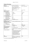
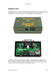
DigiSnap 2000 Series Controllers – User’s Guide DigiSnap 2000 User’s Guide Overview ............................................................................................................... 4 Items included: ................................................................................................ 4 Quick Start............................................................................................................ 4 Camera Compatibility........................................................................................... 5 Serial Interface Cameras ................................................................................ 5 Contact Interface Cameras............................................................................. 5 Wireless (IR) Interface Cameras.................................................................... 5 Pulse Interface Cameras ................................................................................. 6 Camera Cables ................................................................................................ 6 Connection to Terminal ....................................................................................... 6 Standard Operation :............................................................................................ 8 Waking the DigiSnap ...................................................................................... 9 Shutting the DigiSnap Off – Serial Interface Cameras ................................ 9 Shutting the DigiSnap Off – Non-Serial Cameras ...................................... 10 Taking a single picture.................................................................................. 10 Harbortronics Post Office Box 2663 Gig Harbor, WA. USA 98335 253-858-7769 (Phone) 253-858-9517 (Fax) Time-Lapse Photography ............................................................................. 10 Terminal Configuration ..................................................................................... 14 Advanced Time-Lapse Menu........................................................................ 18 Camera Configuration Menu – Single Snap ............................................... 19 Camera Configuration Menu – Time-Lapse ............................................... 22 DigiSnap Operation Menu............................................................................ 24 Switch Menu .................................................................................................. 28 Sales & Service: [email protected] Technical & Customizing: [email protected] Special Features Menu.................................................................................. 33 Battery................................................................................................................. 39 Power Drain................................................................................................... 40 DigiSnap 2000 Variations .................................................................................. 42 DigiSnap 2100 ................................................................................................ 42 DigiSnap 2200 ................................................................................................ 42 Harbortronics 2 Sept 25, 2007 DigiSnap 2000 Series Controllers – User’s Guide DigiSnap 2000 Series Controllers – User’s Guide DigiSnap 2300 ................................................................................................ 42 DigiSnap 2500 ................................................................................................ 42 DigiSnap 2800 ................................................................................................ 43 Service / Warranty .............................................................................................. 44 Overview The DigiSnap 2000 is an electronic shutter release compatible with many digital cameras. The DigiSnap 2000 can be configured to take a single picture, or to take a series of pictures at precise time intervals (Time-Lapse photography). Items included: DigiSnap 2000 AAA Battery, Alkaline (already installed) Cable Assembly, Null-Modem, DB9-F / DB9-F, 6 Ft (For connection to a terminal or computer) Screwdriver, #1 Philips CD Rom – With all manuals Quick Start 1) Connect the DigiSnap to your digital camera via the cable adapter made for your camera. Turn the camera on… most cameras can simply be switched to the normal position for taking pictures, others may have a communication position. 2) Wake up the DigiSnap. This is done by pressing any of the buttons until it flashes yellow (about ½ second). The DigiSnap and camera will exchange some data, which may take several seconds. 3) You may then press one of the four buttons to control the camera. ▼ 5 Harbortronics 3 Sept 25, 2007 Harbortronics Zoom Out (Wide Angle) Press and hold to zoom out. This feature is only available on some cameras. Time-Lapse Control Press quickly to start and stop the Time-Lapse sequence. Hold to set the Time-Lapse interval (one second per flash) Take Picture Press and release to take a picture. ▲ Zoom In (Telephoto) Press and hold to zoom in. This feature is only available on some cameras. 4 Sept 25, 2007 DigiSnap 2000 Series Controllers – User’s Guide Camera Compatibility There are a variety of cameras compatible with the DigiSnap 2000 series of controllers, and many different camera interfaces. Please check on our website for a current list of cameras, and compatibility with the DigiSnap 2000 series. Serial Interface Cameras For many years, the most popular style digital camera for use with the DigiSnap controllers were the Nikon Coolpix cameras, starting with the earliest Coolpix 900 to the Coolpix 8700. These cameras had an relatively standard serial protocol interface, allowing control of a number of camera functions, including shutter release. Each camera model had a slightly different set of features and implementation quirks, and the number of features seemed to decrease with each new camera model. Along with all other manufacturers, Nikon has chosen to remove the remote control capabilities of their lower-end cameras, so the latest Coolpix cameras are no longer compatible. Olympus, Sanyo, Agfa, and others also used a similar interface. While these ‘Serial’ cameras are no longer available new, we find many customers still using them, sometimes buying used cameras in order to have control over the zoom, etc. Serial cameras compatible with the DigiSnap controllers are sold with, or have optional serial cables for connection to a PC type personal computer. The DigiSnap 2000 series controllers provide the same interface connector as a PC computer (DB-9 male), permitting them to be connected directly to the cable. Much of this user guide is written to address the features and quirks of operation with Serial Interface cameras! Contact Interface Cameras The most common camera used for time-lapse operations are SLR cameras. Most models of SLR camera have a shutter release jack, which can be wired to the DigiSnap controller. The interface is very simple, generally just a switch contact. Not all SLRs have a wired shutter release jack however, and many SLRs use proprietary connectors, which increases the price of the cables somewhat. The Rebel series of SLRs from Canon use a very nice simple, industry standard interface, along with most Pentax SLRs. Nikon uses a proprietary 10 pin connector, and the higher-end Canon cameras use a proprietary 3 pin connector. Some SLR manufacturers provide remote control interface via a spare signal on the USB connectors, etc. We can work with almost any SLR interface, as long the camera has a remote shutter release connection! DigiSnap 2000 Series Controllers – User’s Guide Many low cost cameras can be triggered via a simple low cost IR transmitter, available as an accessory from the camera manufacturer. While there are some significant limitations using IR, some customers have used these cameras with our controllers for time-lapse applications. There are three issues of note when using IR. Most cameras will shut the camera’s IR sensors off after a period of inactivity, so a long time-lapse interval (i.e. 15 minutes) may be a problem. We also found that the IR process isn’t always 100% reliable, and occasional pictures may be skipped. The other issue is that the sensors on the cameras are generally in front of the camera, but we can provide a fiber optic cable to route the IR signal from a DigiSnap, to the camera… you tape the enf of the fiber cable to the front of the camera, near the sensor. Currently the DigiSnap 2000 controllers can emulate the Nikon IR transmitters. As we get customer requests, we can generally add the codes needed to control other cameras. Pulse Interface Cameras A few camera models require a particular pulse code to trigger their shutter, such as provided by the Ricoh CA-1 remote cord. As we get requests to control these sort of cameras, we can add codes to our firmware to support them. Currently we do not support the LANC interface as used by a number of Sony cameras. Camera Cables It is quite easy to operate the DigiSnap at distances much farther than that of the standard cables (normally 6 ft). The DigiSnap’s 9 pin connector is industry standard, permitting use of off-the-shelf cables to extend the distance between the DigiSnap and the camera. The maximum distance is dependent on the particular camera interface, and the quality of the cables used. The DigiSnap has been successfully used with a 1000 ft cable! Connection to Terminal The DigiSnap 2000 controllers can be connected to a computer or ‘dumb terminal’ to configure the less often used settings. The terminal may be a personal computer running a terminal emulator program (such as HyperTerminal on a PC, ZTerm on a MAC), or any other device operating as a simple terminal. Many newer computers do not provide hardware serial ports… this is a sore point with many of us electronic developers, but is a fact of life! You may need to buy and install a USB-to-Serial converter, which are commonly available. From customer feedback, we’ve heard that the Keyspan models are excellent, but you may find that any model from any manufacturer may work as well. Wireless (IR) Interface Cameras Harbortronics 5 Sept 25, 2007 Harbortronics 6 Sept 25, 2007 DigiSnap 2000 Series Controllers – User’s Guide DigiSnap 2000 Series Controllers – User’s Guide A null-modem cable is supplied with the DigiSnap 2000 to facilitate connection to a terminal or computer. The data rate is 19.2 KBaud, and the RS-232 format is N-8-1 (no parity, 8 data bits, 1 stop bit), handshaking / flow control should be turned off, and local echo should be disabled. A HyperTerminal setup file is available on the Harbortronics website and CD-Rom, simplifying the configuration for those not familiar with terminal programs. Please refer to the FAQ section of the Harbortronics website for additional information about terminal connections. Standard Operation : Status Indicator The LED on the top of the case indicates how the DigiSnap is working. It may flash green, red or yellow/orange. During operation, the DigiSnap will flash green periodically to signal that it is working properly, and to indicate in which state it is operating. Checking this interval is an easy way to determine the operating state. Flash Period State 4 Sec Simple Time-Lapse 6 Sec Terminal Connection 8 Sec Advanced Time-Lapse 12 Sec Single Snap If an error occurs, the DigiSnap will flash red. The number of times it flashes red before it shuts off indicates the error encountered. Harbortronics 7 Sept 25, 2007 Flashes Error 1 Low Battery The battery in the DigiSnap may need to be replaced 2 Timeout 3 Internal 4 Response 5 Camera The camera may be out of image memory. 6 Checksum A data packet was corrupted. 7 Mode Check the configuration 8 Protocol 10 Unknown The DigiSnap was not able to communicate with the camera. If this occurs regularly, contact Harbortronics. Harbortronics Note There was a problem communicating with the camera. The camera or cables may not be compatible. There may be an internal program glitch, or a hardware problem. The camera did not return the anticipated responses to the commands. There might be some problem with the camera or it may not be compatible. 8 Sept 25, 2007 DigiSnap 2000 Series Controllers – User’s Guide DigiSnap 2000 Series Controllers – User’s Guide Waking the DigiSnap When any switch is pressed and held briefly (about ½ second), the DigiSnap will turn on, and the indicator will flash yellow briefly, indicating that the DigiSnap has awakened and is starting to communicate with the camera. Once communication has been established with the camera, the indicator will flash Green a few times to indicate success, or Red to indicate failure. When using a Serial interface camera, the DigiSnap exchanges a fair amount of data with the camera during startup, such as the time of day, the protocols that the camera will support, etc. It may take several seconds to complete this process with a camera that supports the extended protocol (i.e. later model Nikon Coolpix cameras), and several seconds longer for those that do not. If your camera does not support the extended protocol, you may wish to configure the DigiSnap to use only the Standard protocol, which may speed up the startup process. When connected, the DigiSnap will flash green once if the camera only supports the Standard protocol, and three times for those that support the Extended protocol. If using a camera that does not use a serial interface, the DigiSnap will blink green 4 times to indicate that it is ready. Shutting the DigiSnap Off – Serial Interface Cameras When using a Serial Interface camera, the DigiSnap will turn itself off after a period of inactivity so for most applications this is not a concern. There are times however when you may want to have it shut down more quickly, such as when re-connecting to other devices. When shutting down, the DigiSnap will display a yellow/orange light for about 3 seconds. If an error occurs, then the DigiSnap may shut itself off. In practice, this may be the most common method. If the camera is disconnected, or shut off, then the DigiSnap will periodically ‘ping’ the camera to see if it’s still attached. If not, then it will report a communication error and shut itself off. The frequency at which the DigiSnap checks the camera can be configured (see Operation Menu section). It’s possible to have the DigiSnap check the camera quickly, by telling it to take a picture. If the camera is disconnected or off, pressing the button will cause the DigiSnap to try to communicate with the camera, and an error will quickly occur, shutting the DigiSnap off. Pressing the 5 button may provide an even faster way of shutting the DigiSnap off. When using the Extended protocol, the camera will report to the DigiSnap if it shuts down. When using the PowerSave option however, the DigiSnap does not listen for reports from the camera, so it will miss it. If the PowerSave option is Harbortronics 9 Sept 25, 2007 disabled, the DigiSnap will receive the report and shut down with the camera. This gets slightly more complicated, in that even if the camera is configured to use the Extended protocol, the DigiSnap may switch it back and forth to the Standard protocol to shut the LCD off and save power within the camera. There is a switch function designed to shut the DigiSnap off. If one of the switches is re-mapped to use this function, then pressing the switch will do the job (see the Switch Menu section). Shutting the DigiSnap Off – Non-Serial Cameras As the DigiSnap does not get feedback from cameras without the serial interface, there are generally no errors, so you must manually shut the DigiSnap off when not in use. When the DigiSnap is configured for anything other than a Serial Interface camera, the Zoom switches (the two outermost switches) are automatically configured to shut the DigiSnap off. Taking a single picture A single picture may be taken at any time by momentarily pressing the button. The images captured are retained in the camera, exactly as if the camera were used without a remote control. After each picture has been taken, and stored to the memory in the camera, the DigiSnap will briefly flash green, to indicate success. If there was a problem, the indicator will flash red, and the DigiSnap will shut down (serial cameras only). Note that the DigiSnap 2000 series controller does not alter camera setting. Therefore you should be able to set the camera up manually for most any situation, and the DigiSnap will continue to use those settings. Time-Lapse Photography Time-lapse operation can be used to automatically take a number of pictures with a period of time between each shot. The DigiSnap can use either of two different Time-Lapse techniques, called ‘Simple Time-Lapse’ (STL), and ‘Advanced Time-Lapse’ (ATL). If an error occurs when taking a picture on a Serial camera during Time-Lapse operation, the Time-Lapse process will stop, the DigiSnap will report the error (number of red flashes), wait about 10 seconds and then attempt to restart the sequence. If the error is persistent, the DigiSnap will continue to report / wait / restart. If this is the case, you may need to manually stop the Time-Lapse sequence to allow the DigiSnap to shut down. Note that if a field programmed interval is used, or if the DigiSnap is configured for Single Snap on wakeup, this Harbortronics 10 Sept 25, 2007 DigiSnap 2000 Series Controllers – User’s Guide report / wait / restart process is not used… the DigiSnap will instead shut down if an error occurs. Depending on the particular serial camera model, the camera settings, and DigiSnap settings, it is possible for errors to occur on an occasional (random) basis. Refer to the Operation Menu section for some hints to reduce errors. Any and every critical application should be tested before it is actually used in the field to verify reliability. The DigiSnap controllers are consumer products, and Harbortronics cannot and does not guarantee operation for any critical application. During Time-Lapse operation, the DigiSnap buttons are still active. If there is a need to take an additional picture in between those of the time-lapse sequence, simply press the button, and the DigiSnap will command the camera to take a picture immediately, without interrupting the time-lapse sequence. Similarly, the DigiSnap may be used to control serial camera focal length (zoom in and out) between time-lapse pictures. Simple Time-Lapse A Simple Time-Lapse (STL) sequence consists of an initial delay, followed by a number of pictures taken with a particular interval between each picture. The initial delay can be configured from 0 to 65535 minutes. The initial delay is intended for applications where the system is turned on and started, but some time is required after startup before the scene will be ready, or the equipment set in place. Most applications will simply leave this set to 0 minutes. The number of pictures to capture in the sequence can be set from 1 to 65535, or infinite by entering 0. Many applications require the camera to continue to take pictures until turned off later. The infinite setting is useful for these applications. If left running, the DigiSnap will continue to command the camera to take pictures as long as the batteries last in the DigiSnap and camera, unless an error occurs. The time-lapse interval may be set from 0 seconds, to 255 hrs, 59 minutes, and 59 seconds, which is over 10 days. If the interval is set to 0 hrs, 0 minutes, 0 seconds, then the DigiSnap will command the camera to take a picture as soon as the camera has saved the previous image to memory, so that the camera cycles as fast as possible. Note that the camera may have particular shooting modes that can take pictures in rapid sequence, which may be significantly faster than the cycle time for the camera when remotely controlled. There are three ways to initiate the STL sequence. Harbortronics 11 Sept 25, 2007 DigiSnap 2000 Series Controllers – User’s Guide 1. If the DigiSnap is configured for STL mode (see configuration), then when the DigiSnap is awakened, it immediately starts the STL sequence. At the end of a STL sequence (the programmed number of pictures have been taken), the DigiSnap will flash yellow to indicate that it is shutting down. 2. If the DigiSnap is operating in Single Snap mode, then the 5 button (time-lapse control function) may be used to start and stop an STL sequence. This button can also program the interval in the field (please refer to Switch Menu section for more detail). Note that when the STL sequence is completed, the DigiSnap will revert to Single Snap mode. 3. There is switch function available that does nothing but start the STL sequence. This is also described in the Switch Menu section. Advanced Time-Lapse Photography The DigiSnap can be configured for Advanced Time-Lapse (ATL) photography, where a set of Time-Lapse sequences can be programmed to start at particular times of the day. When using a Serial Interface camera, the DigiSnap automatically acquires the time of day from the camera, so you can specify the exact daily starting time of the sequences. Therefore, at the start of the operation, the clocks are well aligned, but over the course of time, the DigiSnap clock may possibly drift slightly relative to the camera clock. When using a non-serial interface camera, the DigiSnap simply presumes that it is midnight when powered-up, so you must specify ATL sequence start times relative to the power-up time of the DigiSnap, rather than a particular time of day. This makes is slightly less convienent, but it works fine! Up to eight sets of sequences may be programmed to start at particular times of the day. Each sequence consists of a number of pictures to take, and an interval between them. The DigiSnap does not check for overlaps between the programmed intervals, so please plan them carefully. As the ATL process consists of multiple STL sequences triggered per a daily clock, the observant operator may note that the DigiSnap will flash green at either the 8 second period for ATL, or the 4 second period for STL, depending on the operating state at that time. Harbortronics 12 Sept 25, 2007 DigiSnap 2000 Series Controllers – User’s Guide The ATL operation is intended for multi-day unattended applications, and as such will run until either the DigiSnap or Camera batteries wear down, or the sequence manually stopped. There are two ways to initiate the ATL process. 1 If the DigiSnap is configured for ATL mode (see configuration), then when the DigiSnap is awakened, it immediately starts the ATL process. Note that there is no ‘end’ to an ATL process… it will continue day after day. In our integrated Time-Lapse Package, it may continue for years! 2 If the DigiSnap is operating in Single Snap mode, then it is possible to manually start the ATL process, if one of the DigiSnap buttons is re— mapped to that function (see Switch Menu section). DigiSnap 2000 Series Controllers – User’s Guide Terminal Configuration In order to configure the other many settings and options, the DigiSnap is designed to communicate directly to a terminal (or terminal emulator). Once the terminal is set up, the cable connected between the DigiSnap and the terminal, waking the DigiSnap will display a menu of available commands. There is a wealth of features, so several independent menus of configurations are presented. The default configuration is 19.2 KBaud, N-8-1, no flow control, and no echo. Example menus for version 3.50 of the firmware are duplicated below, with descriptions of each command. Depending on the model and selected camera interface of your DigiSnap, not all of these menus or menu items will be available. ***** www.Harbortronics.com ***** DigiSnap 2100 Firmware : Sept 25, 2007, Version 3.50 Main Menu Operating Mode : Single Picture Camera Interface : Serial Simple Time-Lapse Settings # of Shots : 00010 Initial Delay (minutes): 00000 Interval (HHH:MM:SS) : 000:00:05 Commands (enter a single letter) M - Set Operating Mode I - Change the Camera Interface T - Configure the Simple Time-Lapse settings A - Advanced Time-Lapse Configuration Menu S - Camera Menu - Single Snap L - Camera Menu - Time-Lapse Operation O - Operation Menu W - Switch Menu F - Special Features Menu Q - Quit (Save Changes, Shut off) Note that the menu header displays the internet address of Harbortronics, as well as the model number, firmware version and build date. To enter a command, the Harbortronics 13 Sept 25, 2007 Harbortronics 14 Sept 25, 2007 DigiSnap 2000 Series Controllers – User’s Guide DigiSnap 2000 Series Controllers – User’s Guide letter is entered (upper or lower case) followed by the <Enter> key. If the <Enter> is entered without a command, the menu will be refreshed. The maximum interval between pictures is 255 hours, 59 minutes, 59 seconds. The minimum delay can be set to 0 hours, 0 minutes, and 0 seconds, which will essentially tell the DigiSnap 2000 to command new pictures be taken as soon as the camera signals that the picture has been stored (will operate as fast as possible). Depending on the firmware in the particular camera used, an error might occur if operated in this way, causing the DigiSnap 2000 to abort the TimeLapse operation. • M – Set Operating Mode This command will ask which mode to use when the DigiSnap initially wakes up. S - Single Picture T - Simple Time-Lapse A - Advanced Time-Lapse DigiSnap Application (S,T,A)? (S) Single Snap : Most commonly used mode. Does nothing until a button is pressed. (T) Simple Time-Lapse : Starts a STL sequence immediately upon wakeup. (A) Advanced Time-Lapse : Starts the ATL process immediately upon wakeup. • T – Simple Time-Lapse settings Note that if the camera is turned off during a Time-Lapse sequence, the DigiSnap may not detect this and shut off until the next time it tries to take a picture. If the interval is set to a very long period, the or the 5 button can be pressed again to request an immediate operation, to allow the DigiSnap to recognize that the camera is turned off, and shut itself down more quickly. • This command leads to the Advanced Time-Lapse Menu • A Time-Lapse sequence is defined by the initial delay, number of pictures to take, and the interval between them. This command will ask for these numbers. How many pictures to take? (0..65535) [0=Infinite] ? The number of pictures may be set to any number between 0 and 65535. If set to 0, then this indicates to the DigiSnap to take an infinite number of pictures. Effectively this means that the DigiSnap will request pictures as long as the batteries in the camera and DigiSnap are charged, there is memory left in the camera, and an error has not occurred. Minutes to wait before starting STL (0..65535)? The initial delay is normally set to 0, so that the STL sequence starts immediately. If desired, the value can be set to any other number up to 65535, so that the STL sequence will start after a number of minutes. How many Hours between pictures (0..255)? How many Minutes between pictures (0..59)? How many Seconds between pictures (0..59)? A – Advanced Time-Lapse settings I - Change the Camera Interface The DigiSnap 2000 controllers were originally developed to control cameras via a serial port connection, and as time has progressed, we have added the ability to control cameras using other remote control interfaces. This command is used to select which camera interface the DigiSnap should control. 1. 2. 3. 4. 5. Serial Contact (SLR) IR (Nikon) Pulse (Ricoh) Aux Contact (2800 only) If you select a Contact or Aux Contact interface, you will be prompted to enter a number of seconds to hold the ‘shutter release’. This refers to the amount of time that the DigiSnap effectively presses the shutter release button on the camera. Most SLRs are fast enough to wake up and take a picture in 1 to 2 seconds. If your camera is set for auto focus, it may need a longer time. A great number of the available configuration items listed in this menuing section only apply to cameras using a serial port communication interface. If you have any questions about configuring the DigiSnap for your particular camera or application, please contact [email protected]. • S – Camera specific configurations, for single shot operation This command leads to the single shot Camera Configuration Menu Harbortronics 15 Sept 25, 2007 Harbortronics 16 Sept 25, 2007 DigiSnap 2000 Series Controllers – User’s Guide • L – Camera specific configurations, for time-lapse operation This command leads to the Tim-Lapse Camera Configuration Menu • O – Operation settings W – Switch settings This command leads to the Switch Menu • F – Special Features This command leads to the Special Features Menu. The special features are optional extensions to the base firmware adding additional capability, and this menu will not be present unless some features are installed. • Advanced Time-Lapse Menu The DigiSnap can be configured to take a series of Time-Lapse sequences at specific periods of the day. ATL Period # 1 Enabled 00002 Shots, Starting 21:05 Interval 00:00:15 ATL Period # 2 Disabled 00005 Shots, Starting 06:00 Interval 00:00:15 ATL Period # 3 Disabled 00005 Shots, Starting 07:00 Interval 00:00:20 ATL Period # 4 Disabled 00005 Shots, Starting 09:00 Interval 00:00:10 ATL Period # 5 Disabled 00005 Shots, Starting 10:00 Interval 00:00:20 ATL Period # 6 Disabled 00005 Shots, Starting 11:00 Interval 00:00:20 ATL Period # 7 Disabled 00005 Shots, Starting 12:00 Interval 00:00:20 ATL Period # 8 Disabled 00005 Shots, Starting 13:00 Interval 00:00:20 This command leads to the Operation Menu • DigiSnap 2000 Series Controllers – User’s Guide Q – Quit This command is used to disconnect the DigiSnap controller, saving the changes made during the session. If the Q command is not entered, the DigiSnap 2000 will automatically save any changes and shut off after 90 seconds, if no activity is detected. Pressing any of the buttons on the DigiSnap will also shut the DigiSnap off when connected to the terminal. Commands (enter a single letter) 1..8 : Configure Period 1..8 Q - Quit (Return to Main Menu) • 1..8 Select a sequence to configure. Each sequence is independently defined, and can be configured without concern for their particular position in the list. There is no error checking performed on the sequences, so it is possible to define sequences which overlap each other, and overlap the 24 hr period, creating undefined behavior. Each sequence may be enabled or disabled. If disabled, its settings are effectively ignored. The number of pictures may be set from 1 to 65535. The starting time (per the camera’s internal clock) may be set to any minute of the day or night, using a 24 hr format. For example, 19:25 would be 7:25 PM. The interval may be set from 0 seconds to 12 hrs, 59 min, 59 sec. • Q – Quit This command returns control to the Main menu. Harbortronics 17 Sept 25, 2007 Harbortronics 18 Sept 25, 2007 DigiSnap 2000 Series Controllers – User’s Guide required. If your camera supports it, you will probably prefer to set the Protocol to Extended (default configuration). Camera Configuration Menu – Single Snap Some cameras only support a few of the features of the standard protocol, and none of the extended protocol. If a camera fails to respond or locks up when the LCD or Zoom is controlled, then a reduced feature set can be enabled, where the only function used is to take a picture. Protocol Used : Extended Standard Protocol Settings LCD On : Enabled Zoom Step Size : 010 Refresh LCD after Zoom : Disabled Preset Focal Length : 100 • When the serial cable is connected to a digital camera, the camera will typically switch to a low power state, turning the LCD monitor off, and waits for commands. Some models permit the LCD to be turned on or off when using the standard protocol, which is very useful in a number of applications, particularly single snap studio work where the DigiSnap is simply used as a remote shutter release. In more remote applications, it may be desired to use the video output from the camera, which is typically enabled only when the LCD display is on. Commands (enter a single letter) P - Change Camera Protocol S - Change Standard Protocol Options E - Change Extended Protocol Options Q - Quit (Return to Main Menu) There are two menus that control the way the DigiSnap interacts with a Serial camera, one for Single Snap operation, and another for Time-Lapse. This menu is for Single Snap operation. Various features specific to various camera models can be selected. Depending on the camera model, these settings may or may not have any affect on operation. The camera configuration menu does not actually change anything within the cameras, but modifies the commands sent to the camera. P – Camera Protocol S - Standard E - Extended M - Standard, Minimum Features Select the protocol (S,E,M)? In the later Nikon Coolpix cameras (i.e. 880, 885, 990, 995, 4300, 4500, 5000, 5400, 5700, 8700), Nikon has extended the protocol to add a few more features, and improve the responsiveness of the camera to remote control. The camera does not however simultaneously support commands using both protocols, so the DigiSnap firmware will switch the camera back and forth between protocols as 19 Note that when the extended protocol is used, the LCD monitor is normally on, but can be turned off manually at the camera. Even with the LCD off however, the camera uses a huge amount of battery power compared to using the Standard Protocol. Focal Length Step Change (1..50) [.1 mm] ? When using the Standard Protocol, the Zoom In / Zoom Out action is not as smooth as it is with the Extended protocol. The DigiSnap essentially commands the camera to move to a particular focal length value. By setting the step size, different size Zoom steps are taken, allowing fine control, or faster zooming. Note that the step size value is ten times that required. For instance, an entry of 10 will result in a 1 mm focal length change per step. Enable LCD Refresh after Zoom? (Y/N)? Depending on the camera model, some functions may or may not be available. The Standard protocol is common to all of the compatible cameras using a serial port connection, providing a base set of functions to control the camera. Harbortronics S - Change Standard Protocol Options Enable LCD (Y/N)? Extended Protocol Settings Switch Press Option : Half-Press • DigiSnap 2000 Series Controllers – User’s Guide Sept 25, 2007 Some cameras shut the LCD off after changing the focal length value. Enabling this option forces the LCD to be refreshed after each zoom step. This slows the operation down, so should be left disabled unless required. Focal Length (0..255) [.1 mm] ? The DigiSnap can set the camera lens to a specific focal length value, which can be useful for achieving consistent images for stitching or architectural uses. Note that the value entered is ten times the desired focal length. For instance, if a 10 Harbortronics 20 Sept 25, 2007 DigiSnap 2000 Series Controllers – User’s Guide mm focal length were desired, a value of 100 would be entered. Obviously the focal length limits vary among camera models. • E – Extended Protocol Options This determines how the DigiSnap button configured to ‘Take Picture Immediately’ operates. As mentioned previously, the Extended protocol is only supported by some of the Nikon Coolpix cameras. N - Normal H - Half Press B - Bulb Exposure Select the Switch Option (N,H,B)? If set to normal, then pressing the button will cause the camera to take a picture. If the button is held down, the camera will continue to take pictures as fast as the camera/DigiSnap can cycle. When using the Half-Press option, pressing the button on the DigiSnap will effectively ‘half-press’ the shutter release on the camera, allowing it to pre-focus and set the exposure. When the button is then released, the camera will actually take the picture. This provides an excellent way to get the action shot you want! You can cancel the ‘Half-Press’ by pressing any other button at the same time, then releasing them all. When using the Bulb option, if the camera is set to full Manual control, with the shutter speed set to bulb, then the shutter will be held open as long as the switch is held down. The camera may limit the maximum exposure time, depending on the model. Note that the bulb option may also be useful for using the ‘continuous’ modes of the camera! • Q – Quit This command returns control to the Main menu. DigiSnap 2000 Series Controllers – User’s Guide Camera Configuration Menu – Time-Lapse Protocol Used : Extended LCD On : Disabled Extended Protocol Settings Timed Bulb : Disabled Exposure Duration (secs): 00030 Commands (enter a single letter) P - Change Camera Protocol L - Change LCD State E - Change Extended Protocol Options Q - Quit (Return to Main Menu) There are two menus that control the way the DigiSnap interacts with a Serial camera, one for Single Snap operation, and another for Time-Lapse. This menu is for Time-Lapse operation. Various features specific to camera models can be selected. Depending on the camera model, these settings may or may not have any affect on operation. The camera configuration menu does not actually change anything within the cameras, but modifies the commands sent to the camera. • P – Camera Protocol S - Standard E - Extended M - Standard, Minimum Features Select the protocol (S,E,M)? As mentioned in the Camera Protocol section of the Single-Snap camera configuration menu, there are two protocols that can be used to communicate with the later model Nikon Coolpix cameras (880, 885, 990, 995, 4300, 4500, 5000, 5400, 5700, 8700). When performing a time-lapse operation, the DigiSnap will always switch the camera back to the standard protocol to save power, but when taking the picture, you have the ability to select which protocol is used. When performing Time-Lapse operations, the standard protocol is often preferred, as there are fewer commands exchanged between the camera and DigiSnap, providing perhaps a bit more reliability, and the LCD on the camera may be kept off, minimizing the power drain. Harbortronics 21 Sept 25, 2007 Harbortronics 22 Sept 25, 2007 DigiSnap 2000 Series Controllers – User’s Guide If you find any issues with exposure accuracy when using the standard protocol, by all means try the Extended protocol… some cameras have a problem with exposure control when using the Standard protocol. When using the Coolpix 5400 or 8700 cameras, it is advised to use the Extended protocol, as these particular camera models only revert to the low power state when switching back from the extended protocol to the standard protocol. • L - Change LCD State Enable LCD (Y/N)? In long Time-Lapse applications, battery power can be a concern. By disabling the LCD of the camera, the battery life can be maximized. Note that when using the Extended protocol, the LCD is likely to come on for each shot, regardless of this setting. This is normal. • E – Extended Protocol Options Enable Timed Bulb Exposure (Y/N)? Bulb Duration (1-65535 seconds)? If not enabled, the DigiSnap will momentarily activate the shutter release at each time-lapse interval. This is generally used with the camera set for auto-exposure. The Bulb feature for Time-Lapse is unique, allowing the shutter to be held open for a programmable period of time during Time-Lapse photography. The most obvious application is for astrophotography. The camera must be set to fully manual, bulb shutter, and the DigiSnap to Time-Lapse. When this feature is enabled, the duration to hold the shutter open is programmable, and may be set from 1 to 65535 seconds. The camera itself will most likely limit this time to a shorter interval, such as 1 minute or 5 minutes, depending on the camera. A clever use of this for to set the DigiSnap Time-Lapse to take a single picture with no delay, and effectively have a single-shot programmable Bulb exposure at a single button press, using the Time-Lapse Control button function button. • Q – Quit This command returns control to the Main menu. DigiSnap 2000 Series Controllers – User’s Guide DigiSnap Operation Menu DigiSnap Operational Constants Baud Rate to Terminal: 19200 Baud Max # of Retry Attempts : 005 Max # of ReConnect Attempts : 002 ReConnect Delay : 010 Power Up Delay : 125 Comm Gap Delay : 010 Post-Save Delay : 000 SafeWait Delay : 100 Camera Check Period : 006 Power Savings : Enabled FailReset : Disabled FailReset Delay : 010 Commands (enter a single letter) B - Change Terminal Baud Rates F - Reset everything to Default P - Change PowerUpDel constant C - Change CommGap constant V - Change SaveDel constant W - Change SafeWait Delay constant X - Change CamChkPer constant A - Change MaxAttempt constant R - Change MaxReConnect constant D - Change ReConnect Delay constant Y - Change Power Savings Enable J - Change FailReset Enable K - Change FailReset Delay constant Q - Quit (Return to Main Menu) This menu provides some control over how the DigiSnap performs detailed internal operations. There are cases where specific camera models benefit from using different time constants. For instance, the Coolpix 950 seems to be more prone to locking up when the LCD is enabled. Increasing the CommGap value seems to mitigate this nicely. • B – Baud Rate The communication baud rate to the terminal may be programmed. The default is 19200 baud, but it may be reduced to as low as 150 Baud if required. Note that the camera baud rate is fixed at 19200 baud. Harbortronics 23 Sept 25, 2007 Harbortronics 24 Sept 25, 2007 DigiSnap 2000 Series Controllers – User’s Guide • • F – Factory Defaults This command restores many configuration items to their factory default settings, typically helpful if you have ‘played’ around with some of the constants, and want to revert back to a known state. • P – Power Up Delay The actual delay is 13.333 mS times the number entered. For instance the default value of 125 yields a delay of 1.667 seconds. To speed up the startup process, feel free to reduce this value, and give it a try. C – CommGap A short delay is inserted between each Standard protocol command to the camera; to allow it time to process that command before the next one is sent. Various camera models require different minimum delays. Delay between Packets (1..255)? The actual delay is 13.333 mS times the number entered. For instance the default value of 10 yields a delay of 133.333 mS. It’s possible to speed up the communication process by reducing this delay, and it may be possible to increase reliability by increasing this delay. • V – Post Save Delay After each picture is taken, and saved to memory, the camera will report to the DigiSnap that the process is completed. In earlier versions of DigiSnap firmware, the reports were not handled as well, so an additional delay was added after the camera reported it was ready. This delay may no longer be required. Delay after taking picture (0..255)? W – Safe Wait Delay With some Coolpix cameras, an additional delay appears to mitigate the likelihood of having a fairly rare lockup of the camera during a particular operation. This issue is most often found with Coolpix 5000 cameras, but has been noticed with other models as well. • During the startup process of establishing communication with the camera, a delay is inserted between the setting of the ‘DTR’ signal and communication with the camera, in order to give the camera some time to wake up. In most cases this is not required, while in some cameras that make use of the DTR signal, if commands are sent too soon, the camera will lock-up, requiring the camera batteries to be removed momentarily to re-establish operation. Power Up Delay Value (1..255)? • DigiSnap 2000 Series Controllers – User’s Guide X – Camera Check Period The DigiSnap will periodically poll the camera to see if it is still connected, and working. If not, the DigiSnap will shut itself off. Half-Minutes between checking camera? (1..59)? The actual period is 30 seconds times the number entered. The default value of 6 yields a camera check period of once every 3 minutes. During the short period when the DigiSnap polls the camera, the DigiSnap may be unresponsive to button presses, or an additional delay may accrue before the command is executed. The camera check operation also consumes more battery power in both the DigiSnap and the camera than the idle states. It may be desirable to extend the camera checks out as long as possible in some applications, such as long term time-lapse. On the other hand, if you disconnect the camera from the DigiSnap, the DigiSnap may continue to think it is connected for quite a while, making it frustrating to reconnect to the camera. If you frequently disconnect the DigiSnap from the camera for image review or other requirement, you may want to reduce the camera check period. The Coolpix 5400 and 8700 have an operational quirk in that they do not revert to a low power state after a camera check. When performing time-lapse operations with the 5400 or 8700, you may want to set the CamChkPer to 0 to prevent camera checks entirely, and minimize the power draw. • A – MaxAttempts The serial port communication protocol with the cameras has a number of quirks, and each new camera model seems to introduce different quirks. In general, the process is reliable, but it is not uncommon for some communication issue to arise. In some situations, such as during a long term time-lapse in a remote area, failures become expensive. The DigiSnap uses a three-stage error resolution process in an attempt to recover from communication errors. The actual delay is 13.333 mS times the number entered. If your particular camera model occasionally fails to respond to commands after a picture has been taken, you may try to increase reliability by increasing this delay. The first stage of error resolution is to simply repeat commands that do not yield an appropriate response from the camera. The MaxAttempts constant defines how many times the DigiSnap should simply resend a command. In practice, resending a command 3 times seems sufficient to cover most issues, and there does not seem to be much utility in increasing beyond 5. Harbortronics Harbortronics 25 Sept 25, 2007 26 Sept 25, 2007 DigiSnap 2000 Series Controllers – User’s Guide • If FailReset is enabled, the DigiSnap will wait a number of minutes if a communication error occurs, and then resets completely. The FailReset Delay constant sets that number of minutes. R – MaxReConnect When a communication error occurs, and re-sending commands doesn’t fix the problem, often times the camera will internally clear the issue in a few seconds. The second stage of error resolution is to wait for a period of time and then try to re-establish a link with the camera. • D – ReConnect Delay Y – Power Save By enabling this option, the DigiSnap will consumes the least amount of power, by shutting down the serial interface between commands. This option is enabled by default. Enable Power Savings? (Y/N)? Since the release of Version 2 of the firmware, the power is much better managed by the DigiSnap, reducing the power consumption significantly, even without this option set. The only condition that this option is now active is when the Extended Protocol is active, and the LCD is enabled. When the power save feature is enabled, the DigiSnap does not listen for camera messages except when commands are sent. If the Power Save option is disabled, the DigiSnap will ‘hear’ messages from the camera, and will shut down immediately when the camera is turned off. • J – FailReset During a communication error, if the re-connection process fails, the DigiSnap is generally configured to shut itself off. In general use this is an acceptable action, as it allows the operator to try to fix the problem. In long-term time-lapse installations, this can be unacceptable… if the camera system is only serviced once a month, no images will be captured during that time. The third level of error resolution is FailReset, where the DigiSnap will wait an additional period of time, and then internally reset itself completely, as if the power had been cycled. If enabled, the DigiSnap will never shut off due to communication errors, but will continue to employ all three stages of error resolution as long as the power is applied. • • Q – Quit This command returns control to the Main menu. Switch Menu The ReConnect delay is the number of seconds to wait after a communication error, before trying to re-connect communication with the camera. • DigiSnap 2000 Series Controllers – User’s Guide Switch 1 Function : C Zoom Out Switch 2 Function : L Start ATL Switch 3 Function : B Take Picture Immediately Switch 4 Function : D Zoom In External Switch Function : B Take Picture Immediately Trigger Delay (Switch Function O) : 03000 Commands (enter a single letter) 1 - Configure Switch 1 (Far Left) 2 - Configure Switch 2 (Center Left) 3 - Configure Switch 3 (Center Right) 4 - Configure Switch 4 (Far Right) 5 - Configure External Switch D - Set Trigger Delay Q - Quit (Return to Main Menu) The DigiSnap 2000 is unique in that the user may configure the switch functions. There are a number of potential camera control features that are not currently utilized by the DigiSnap, so there is a possibility for future upgrades to add functionality to the DigiSnap. Even now, four buttons are obviously not able to simultaneously control them all. The user may configure the action for each switch independently, allowing for selection of the features most appropriate to the task at hand. The default mapping is perhaps the most appropriate for normal remote shutter release operations. Note that the DigiSnap 2000 controllers have the capability to be triggered from an external electrical signal, which could range from a simple switch to a light beam detector. We have the capability to develop custom devices to suit your needs! The DigiSnap 2000 is designed to accommodate a small ‘daughter board’ inside the case, to tailor the DigiSnap to almost any conceivable custom application. Contact Harbortronics if you have a particular custom application in mind! We have already worked with a number of photographers and commercial companies to develop special purpose equipment. K – FailReset Delay Harbortronics 27 Sept 25, 2007 Harbortronics 28 Sept 25, 2007 DigiSnap 2000 Series Controllers – User’s Guide • DigiSnap 2000 Series Controllers – User’s Guide E. 1..5 – Configure Switch function As of version 3.50 there are 19 switch functions defined: When pressed and held for an extended time, the Simple Time-Lapse interval can be programmed in the field! After being held for about two seconds, the DigiSnap will flash yellow each second, allowing the user to count off the desired time interval before releasing the button. The number of pictures is automatically set to infinite, and the initial delay set to zero. Once programmed, the Time-Lapse operation may be started by pressing the button again briefly. Pressing the button briefly when the time-lapse in progress will halt the time-lapse operation. A Do Nothing B Take Picture Immediately C Zoom Out D Zoom In E Time-Lapse Control F Toggle LCD Monitor On/Off G Switch DigiSnap Off H Set to programmed focal length I Toggle Protocol J Toggle FastSnap K Start STL L Start ATL M Stop TimeLapse N Toggle STL O Take Picture after Delay P Toggle Stepper Motor Direction Q Rotate Stepper Motor R Step Stepper Motor S Toggle MultiSnap For example… Let’s say you are using the DigiSnap as a simple shutter release to take some studio portraits, and decide that you would like to pose with your model. One way is to use a long extension cord on the DigiSnap, and then try to hide it behind you when you take the picture. Secondly, you could use the DigiSnap 2500’s IR Remote feature to take picture without a cord. Again, you have the problem of hiding the remote, and also of being self-conscious of the camera’s timing. A. Do Nothing Pressing the button will not do anything. B. Snap – Take a picture Pressing the button will cause a picture to be taken immediately, even during a Simple or Advanced Time-Lapse operation. C. Zoom Out Changes the focal length of a Serial camera, for a wider angle image. When using the Extended protocol, the action is quick and responsive. When using the Standard protocol, the action is much slower, and changes in programmable increments. There are some cameras that do not support this command at all. D. Zoom In Changes the focal length of a Serial camera, for a telephoto image. When using the Extended protocol, the action is quick and responsive. When using the Standard protocol, the action is much slower, and changes in programmable increments. There are some cameras that do not support this command at all. Harbortronics 29 Time-Lapse Control When pressed very briefly (i.e. less than one second), the Simple TimeLapse sequence will be alternately started and stopped. Sept 25, 2007 What you could do instead is quickly set the DigiSnap to take pictures every 5 or 10 seconds. You press and hold the 5 button (time-lapse control function), and after a couple seconds it starts to flash yellow. Keep holding it until you count off say 8 flashes (8 seconds), and release it. Press it again briefly, and it will start taking pictures at the every 8 seconds! Walk over and pose, and away you go… after a few shots you lose track of the camera timing, and you begin to look more natural in the resulting pictures. When you are finished, simply press the button again briefly, and the DigiSnap returns to operating as a simple shutter release. Perhaps you are on safari at your local park or zoo, and you see some wild animal staking it’s prey, you notice that a skywriter is spelling out a message, that the clouds are doodling wonderfully, your child is happily climbing a tree, or the fireworks show is about to begin. Shooting movie sequences is not really appropriate for the slower action, and you’d rather sit back and watch than baby-sit the camera. Within seconds you’ve configured the DigiSnap, and it’s taking a sequence of pictures for you, that you can convert to a movie when you return from safari. The field-programmed interval is not retained when the DigiSnap turns off. When the DigiSnap is turned back on, it will use the interval last configured via a terminal. Harbortronics 30 Sept 25, 2007 DigiSnap 2000 Series Controllers – User’s Guide F. LCD Monitor Toggle (On/Off) Pressing the button will alternately turn the camera’s LCD monitor on and off. Note that when using the extended protocol (Nikon Coolpix), the LCD cannot be remotely turned off. G. Power Off When pressed, the DigiSnap will shut itself off, and will command the camera to switch to a low power setting as well. H. Focal Length This function allows the camera zoom to be set to a repeatable, programmable position. This function is not available when using the extended protocol (Nikon Coolpix). I. DigiSnap 2000 Series Controllers – User’s Guide additional delay can be used, which can be useful in some situations. For instance, in a group picture or self-portrait, you may want to hide the DigiSnap from being in the picture, or move to a different location after triggering the remote control before the camera actually takes the picture. A more advanced scenario is multi-camera operation. By triggering a number of DigiSnap controllers simultaneously, each of which are programmed with different trigger delays, each camera will take a picture at different times. Trigger Delay (mS)? (50..30000) ? Note that the trigger delay can be configured for any value from 50 mS to 30 seconds, allowing for a wide and precise range of delays. Toggle Protocol As touched on previously, the DigiSnap can communicate via the Standard and Extended protocols. With this version of firmware, the DigiSnap performs most of the protocol switching automatically, but some advanced operators may find it useful to switch between them manually. P. Toggle Stepper Motor Direction When pressed, the configured stepper motor direction is changed. Q. Rotate Stepper Motor When pressed, the DigiSnap will cause the stepper motor to rotate the number of steps configured in the Special Features menu. J. Toggle FastSnap When pressed, the DigiSnap toggles in and out of FastSnap (see Special Features section). R. Step Stepper Motor When pressed, the DigiSnap will cause the stepper motor to make a single step. K. Start STL When pressed, the DigiSnap will start the STL sequence. Note that this is different than the Time-Lapse Control function in that the time-lapse interval cannot be field-programmed, nor can the STL sequence be halted with the same button. S. Toggle MultiSnap When pressed, the MultiSnap feature will be enabled or disabled in turn. L. Start ATL When pressed, the DigiSnap will start the ATL sequence. Each DigiSnap 2000 series controller is shipped with a default set of switch functions. The standard configuration for a Serial camera interface is defined below. If you are using a camera with a non-serial interface, switches 1 and 4 will generally be configured to shut the DigiSnap off. M. Stop Time-Lapse When pressed, the DigiSnap will stop any Time-Lapse sequence in process, STL or ATL. Switch 1 (▼) is set for Zoom Out. N. Switch 4 (▲) is set for Zoom In. Switch 5 (External Signal) is set for Snap. O. Toggle STL If pressed in Single Snap mode, the DigiSnap will start the STL sequence. If in STL, pressing the button will stop the STL, and switch to SingleSnap mode. Note that this function does not allow for field configuration. Take Picture after Delay When the DigiSnap is triggered (i.e. button press, external event), an Harbortronics 31 Sept 25, 2007 Switch 2 (5) is set for Time-Lapse Control. Switch 3 () is set for Snap • Q – Quit This command returns control to the Main menu. Harbortronics 32 Sept 25, 2007 DigiSnap 2000 Series Controllers – User’s Guide DigiSnap 2000 Series Controllers – User’s Guide Special Features Menu most of the small camera IR transmitters sold for various camera models, as well as any TV remote controller. The IR trigger feature is useful for wireless control of cameras that don’t already have an IR sensor. IR Trigger : Enabled IR Trigger Action : B Take Picture Immediately Enable IR Trigger? (Y/N)? The IR trigger function may be disabled, to save power within the DigiSnap 2500, or if used in areas where other IR controllers might accidentally trigger the DigiSnap. External Output Active : Disabled Output Enabled before Snap : 000 Output Disabled after Snap : 000 Output Active High Switch Function (A..S)? FastSnap : Disabled The IR trigger may be configured to perform any of the standard switch functions. It cannot be continuously held, so it is not appropriate for all applications. STLPreface : Disabled Stepper Motor Active : Disabled Rotate Between MultiSnaps: Disabled Number of Steps between Snaps : 00240 Stepping Speed (mS) : 004 Initial Direction : 000 Active Hold : Disabled Motion Control : Unidirectional Rotation • Enable External Output? (Y/N)? External Output Enabled Before Snap (0..255 seconds)? External Output Disabled After Snap (0..255 seconds)? Commands (enter a single letter) O - Configure External Output Feature F - Configure FastSnap Feature P - Configure STLPreface Feature M - Configure Stepper Motor Feature N - Configure MultiSnap Feature Q - Quit (Return to Main Menu) The DigiSnap family of controllers is periodically updated with new features. Some of these features are made available for all DigiSnaps, via firmware updates, and some features are only supported by specific models of DigiSnap. Other features are optional, and available for an extra charge. Contact Harbortronics if you would like to enable a feature that is not already supplied with your DigiSnap model. I – Infrared Trigger (DigiSnap 2100, 2500, 2800) The external output is an electrical signal designed to roughly synchronize with the shutter of the camera. Roughly means that it is not intended to synchronize a strobe. The output signal is useful to control some low power lighting, drive a relay to control higher power lights, or perhaps pre-charge a strobe. Other uses might include motion control, etc. MultiSnap : Disabled Number of Snaps per Trigger : 001 • O – External Output The output signal becomes active a configurable number of seconds before the camera takes a picture, and turns back off again a programmable number of seconds after the shutter closes and the image is saved to memory. For most lighting applications, simply setting these values to zero will be sufficient. If this signal is used to pre-charge a strobe, or to activate a window wiper, then you may want to set the ‘Before Snap’ appropriately. External Output Active High or Low (1/0)? The output of the DigiSnap can be configured to be ‘active high’ or ‘active low’. The majority of devices will likely expect the Active High setting. • (DigiSnap 2500 only) F – FastSnap When an IR transmission is detected, the DigiSnap can be configured to perform some action, typically taking a picture. Note that this feature should work with There is typically a significant delay (up to several seconds) between when the DigiSnap is triggered, and when a Serial camera actually takes a picture, due to auto-focus and exposure processes. On the camera itself, it’s possible to press the Harbortronics Harbortronics 33 Sept 25, 2007 34 Sept 25, 2007 DigiSnap 2000 Series Controllers – User’s Guide DigiSnap 2000 Series Controllers – User’s Guide shutter halfway, setting the auto-focus and exposure, whereby pressing the shutter the rest of the way will take the picture very quickly. This is also possible using the Half-Press option with the Extended protocol. There are a lot of configurations possible here, but don’t worry… it’s not difficult to figure out what you want, particularly since you can try some settings one way, test it, and make changes! The FastSnap optional feature automatically sets the camera to half-press state after each picture, so that each successive trigger of the DigiSnap will cause the camera to take a picture with minimum delay (on the order of 0.1 seconds). This feature is most useful for situations where the object distance and lighting do not change significantly from shot to shot, and where remote triggering of the DigiSnap is desired, such as when a Serial camera / DigiSnap is mounted behind a glass backboard at a basketball game, and is controlled via wireless control. Enable Stepper Motor? (Y/N)? FastSnap is not used with any camera interfaces other than Serial. Rotate Between MultiSnaps? (Y/N)? The stepper motor movement can be selectively activated during MultiSnap pictures. In most situations, the Motor would also be active during MultiSnap, but if you are using MultiSnap in conjunction with exposure bracketing in your camera, you may want to disable motion between MultiSnap pictures. This can be really helpful when taking panoramic shots on a turntable (Such as the Snap360 product). Enable FastSnap? (Y/N)? Steps between Snaps (0..65535)? This command enables or disables the use of the FastSnap feature. Note that is possible to toggle the FastSnap feature on and off using one of the DigiSnap buttons as well (FastSnap Toggle function). • P – STLPreface The STLPreface feature is useful in conjunction with the Simple Time-Lapse delay. For instance, if you want to start a Time-Lapse project but don’t need it to start taking pictures for a while after setting up the equipment, you might choose to use a long delay before the STL starts. The first time you do this, you sit there and wonder… is it working? The STLPreface features give you confidence that the time-lapse process is working. With STLPreface enabled, the DigiSnap will take 5 pictures spaced about 15 seconds apart, right after you start the time-lapse process, and before it starts the delay timer. This lets you know if everything is working correctly! Enable STLPreface? (Y/N)? This command enables or disables the use of the STLPreface feature. • M - Stepper Motor (DigiSnap 2800 only) This requires some knowledge of your stepper motor mechanical setup, and some forethought on your application. How much motion do you want between successive shots? Lets take the example of the Snap360 turntable. Let’s say we want to do a stitched panoramic, where we take 15 pictures in a circle. The Snap360 is geared so that there are 2400 steps needed to rotate in a full circle (360 degrees), so for 15 pictures in that circle, 2400/15 = 160 steps per picture. Stepping Speed (1..255 mS)? This value depends on the mechanics of your system, the load on the motor, etc. The best way to determine the stepping speed (or more precisely, the time between steps) is by experimentation. You might try setting the speed to 10 mS to start with, and see if the motor runs OK… put some additional drag on the system and see if the motor seems to miss some steps. Play with the speed until you can get the system to move to the next position as quickly as possible, without any loss of control. Stepping Direction (1/0)? The DigiSnap 2800 has the ability to control a stepper motor, allowing for some simple motion control photographic applications. After each picture is taken, the DigiSnap can cause the motor to rotate, placing the camera or an object in a new position, to get ready for another shot. In a time-lapse application, the picture will be taken, then the motor activated, and then the DigiSnap will wait for the next time-interval to pass before taking the next picture. This means that the DigiSnap is not intended to control a motor for continuous motion while taking pictures. This also depends on the mechanics… how is the motor wired, is some sort of transmission that may change the direction, etc. Try it one way, and change it if needed! Harbortronics Harbortronics 35 Sept 25, 2007 Enable Active Stepper Hold? (Y/N)? You can select whether to have the DigiSnap keep the motor windings energized after it has reached the new position, in order for the motor to ‘lock’ itself into 36 Sept 25, 2007 DigiSnap 2000 Series Controllers – User’s Guide DigiSnap 2000 Series Controllers – User’s Guide position. If you are operating from batteries, or are worried about heating up your motor, you should disable the active hold. On the other hand, if you have an imbalanced load, making the motor coast between pictures, or the wind may drag the motor out of position, the active hold may be very useful! pictures in quick succession each time you trigger it. If you are doing a long timelapse sequence, and know that the exposure is going to change over time, but don’t want the camera to use auto-exposure, autobracketing and MultiSnap can be used to take a quick sequence of shots at each time-lapse interval, giving you a wider range of exposures to chose from. Set Motion Control mode This configuration allows for some flexibility in your motion control application. Most times, you simply want the motion of the camera or object to continue in the same direction for all shots. If you have an application where you want to periodically reverse the motion, or even have the motion reset to a known position and start again, this is also possible. Option C, continuous motion causes the motor to always operate in the same direction, shot after shot. The other frequent use for MultiSnap is when doing time-lapse panoramas, again using the Snap360. Let’s say you are taking 15 pictures in a circle, and want to have the system repeat this every hour, automatically. No problem… set the timelapse interval for 1 hour, and enable MultiSnap for 15 shots! • Q – Quit This command returns control to the Main menu. Option R, reverse, causes the motor to reverse directions after it reaches a certain number of steps. Option S, sweep, causes the motor to rewind to a known position after a certain number of shots, and start taking pictures with motion in the original direction. When selecting Reverse or Sweep, there is one additional parameter you need to configure… the number of steps in the range. Steps from Center to Limit (0..32767)? Let’s consider the Snap360 again, and this time, let’s do a series of panoramas, but instead of using the full 360 degrees, let’s limit the rotation over a 90 degree angle. So, 2400 steps / 360 degrees * 90 degrees = 600 step range. The way the process works is that the DigiSnap will rotate over half of this range, and then either change directions, or sweep back to the other extreme and start rotating in this same direction. Wherever the camera or object is located when the DigiSnap starts the sequence is considered the midpoint of the range. So the number we need to enter for this parameter is ½ of the 600 step range, or 300 steps. • N - MultiSnap MultiSnap is a feature which allows the DigiSnap to take a number of pictures for each trigger event, such as a press of the button on the DigiSnap, or when a timelapse interval has elapsed. This can be very useful in a couple applications. Many cameras have the ability to autobracket exposures. For instance, with autobracketing enabled in the camera, each successive picture will be taken with a slightly different exposure, over a set of say 5 shots. If you enable MultiSnap in the DigiSnap, and set it for 5 shots, the DigiSnap will automatically take 5 Harbortronics 37 Sept 25, 2007 Harbortronics 38 Sept 25, 2007 DigiSnap 2000 Series Controllers – User’s Guide DigiSnap 2000 Series Controllers – User’s Guide Power Drain Battery The DigiSnap 2000 controllers (except the 2800) are shipped with a battery installed, to allow immediate use. It’s possible in shipment that a DigiSnap button could be repeatedly or continuously pressed, draining the battery before it arrives. The DigiSnap uses a single AAA size battery. Alkaline batteries are the preferred type, as they will yield the longest life under normal use. Two screws must be removed from the case to access the battery, and a small Philips screwdriver is shipped with each DigiSnap to facilitate this operation. The battery polarity is indicated by a simple drawing on the circuit board. Installing the battery backwards will not damage the DigiSnap 2000 or battery, but the DigiSnap will not work, and the battery will be drained rather quickly. The load on the DigiSnap battery depends greatly on the particular state of operation. The battery life is therefore difficult to predict. The following sections calculate the battery life under optimistic scenarios. Given that the battery drain is significantly higher when the LED is periodically flashed and communicating with the camera, the battery life could be a fraction of these theoretical times, depending on your actual use. The DigiSnap converts the battery voltage to an internal 5V supply, and there is a minimum of about 1.1V required to operate. The DigiSnap monitors the battery voltage at startup, and will shut down unless the battery voltage is sufficient. This is a safety feature to eliminate possible flash memory erasures. This also dictates the use of primary battery chemistry (i.e. Alkaline) rather than rechargeable batteries. For applications that require very long term operation, larger cell sizes may be used (wired to the battery terminals), or batteries can be used in parallel or/or series combinations up to 3.5V to power the DigiSnap. The DigiSnap 2500 and 2800 also provides access to the internal 5V supply, for those applications where you have access to a regulated 5V AC adapter. DigiSnap Off When the DigiSnap is off, there is a load of 8-10 uA on the battery. Given that an Alkaline AAA cell is rated for about 1150 mA-H, a DigiSnap battery should theoretically have a shelf life of many years if not used. Note that a new battery is installed at the factory, but occasionally a button may be pressed during shipment, causing the DigiSnap to drain the battery significantly before arriving at the customer. DigiSnap Idle Extended Protocol, LCD On, PowerSave Option Disabled This configuration is perhaps the most responsive, in that the DigiSnap recognizes immediately when the camera has been turned off. The trade-off is that the DigiSnap draws about 39 mA continuously from the battery in this condition. The battery life is theoretically about 1 day if left operating in this state. Other Configurations When the PowerSave option is enabled [factory default], or if the Camera LCD is off, or if using the Standard Protocol, the idle current drain is only 5-6 mA from the battery. This is also true when the interface is set to Other. The serial port uses a significant amount of power, so when controlling an SLR camera, the DigiSnap will last significantly longer than when controlling a Coolpix. Harbortronics 39 Sept 25, 2007 Harbortronics 40 Sept 25, 2007 DigiSnap 2000 Series Controllers – User’s Guide DigiSnap 2000 Series Controllers – User’s Guide The battery life is theoretically about 9 days if left operating in this state. Terminal When connected to a terminal, the DigiSnap draws about 90 mA continuously from the battery. Active Communication During the bursts of communication with a camera, and when the LED is on, the DigiSnap draws significantly more power from the camera. This load is also dependent on the device(s) connected to the serial port of the DigiSnap. The current drain will generally be about 50 mA, with occasional peaks as high as 150 mA. It’s clear that the battery life can be strongly affected by the amount of interaction with the camera. DigiSnap 2000 Variations There are a number of variations within the DigiSnap 2000 family of controllers. The DigiSnap 2000 is the base model, and only interfaces to Serial cameras. The other models provide additional input / output capability, for controlling other devices, or to be triggered from external devices. Each of these controllers have a separate manual describing their features in more detail, so this section is merely an introduction. Given the lack of new Serial interface cameras, the DigiSnap 2000 has been discontinued as of Sept 2007 Please note that all of the DigiSnap 2000 controllers use the same case labeling… they will all say DigiSnap 2000. DigiSnap 2100 The DigiSnap 2100 is a simple variation of the DigiSnap 2000, where an additional input signal, and an output control are connected via the DB-9 connector. The External Output control feature is also provided in the firmware. An optional feature for the DigiSnap 2100 is the IR Output feature. The DigiSnap 2100 is designed to work with any supported camera interface, serial or not, and therefore is recommended to most photographers. DigiSnap 2200 The DigiSnap 2200 has an additional jack on the case for use with an external switch, and is often used with as a foot switch (doctors, copy stands) or mouth switch (skydivers). As of Sept 2007, the DigiSnap 2200 can operate via all supported camera interfaces. DigiSnap 2300 The DigiSnap 2300 was a specially modified version for use in underwater camera systems. It has been supplanted by the DigiSnap 2800, so it was discontinued as of 2003. DigiSnap 2500 The DigiSnap 2500 has a number of additional connections. A four pin connector on the side of the case allows access to the internal power, as well as an input signal, and a medium power switched output. The switched output is intended for Harbortronics 41 Sept 25, 2007 Harbortronics 42 Sept 25, 2007 DigiSnap 2000 Series Controllers – User’s Guide DigiSnap 2000 Series Controllers – User’s Guide controlling devices such as low power DC lighting, or a relay for high power lighting. There is also an IR input receiver on one side of the case, allowing the DigiSnap to be triggered from an IR transmitter, such as a TV remote. Note: Many cameras now include IR sensors, and the DigiSnap 2800 has greater capability for working with external devices, so the DigiSnap 2500 was discontinued as of Dec 2005. DigiSnap 2800 The DigiSnap 2800 is the pinnacle of the DigiSnap 2000 family, having a great deal of additional connection capability. The 2800 has the ability to control a stepper motor, for motion control photography. There are two sets of output control signals, one is an opto-isolated switch, for controlling SLR cameras and other sensitive equipment, and the other is medium power switch, for controlling power to various external equipment. The 2800 also has a connection for an external trigger signal. Service / Warranty All Harbortronics products are warranted against any manufacturing defects for a period of one (1) year from the date of purchase. Defective products should be returned prepaid to Harbortronics. Harbortronics will at its discretion, repair or replace such products without charge, and will return to the customer prepaid. Except as mentioned above, no other warranty expressed or implied, applies to this Harbortronics product. All other claims, of any nature, including but not limited to camera damage are not covered. This warranty does not cover damage caused by misuse, accident, or abuse. This warranty does not cover consequential damages or other incidental damages. Some states do not allow the exclusion or limitation of incidental or consequential damages, so the above exclusions may not apply to you. Contact Harbortronics at www.Harbortronics.com for service instructions. The 2800 does not have a connection for an internal battery, so an external power source must be provided. It can be powered from a regulated 5V supply, or from a battery voltage of 6V to 16V, making it very useful in long term time-lapse applications in the field, where a 12V battery provides power to the camera and DigiSnap. When connecting to a Contact style camera interface, the DigiSnap 2800 has two options. The first is the same as the DigiSnap 2100 Contact output, which can be used with any supported SLR camera. There is also an Aux Contact output, which can be used with many SLR models, but not the Nikon 10 pin, for rather obscure reasons. The Aux Output is preferred in most cases, as it then allow use of the External Output for other device control. Harbortronics 43 Sept 25, 2007 Harbortronics 44 Sept 25, 2007