1
2.1
I2C Bus Hardware Architecture
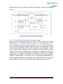
I2C bus defines a data signal line SDA and a clock signal line SCL which supports
bidirectional data transfer between a master and several slaves. Regardless of how
many devices are attached to the I2C bus, there are only two signals connected to
all of them. A master is the device which initiates a data transfer on the bus and
generates the clock signals to permit that transfer. The device being addressed by
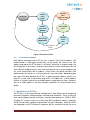
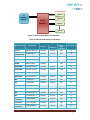
the master is called a slave. In Figure 1, the typical microcontroller (MCU)-based
system use I2C bus for communication between the host MCU and multiple
peripherals, such as memory, LCD drivers, data conversion devices, etc. In this
case, the MCU is the master and the peripherals are slaves. Both the master MCU
and slave peripherals can receive and transmit data.
In I2C bus, both SDA and SCL are connected to a positive supply voltage (VCC)
through pull-up resistors (see in Figure 1). Because SDA and SCL are open-drain,
the devices connected to I2C bus can only drive these lines low or leave them open.
The pull-up resistors RP pull the line up to HIGH (VCC) when the bus is free, or there
is no device on the bus. RP commonly ranges from 1 kΩ to 10 kΩ, resulting in typical
pull-up currents of about 1 mA and less.
So far we discussed a single master implementation of I2C bus. But I2C bus is in
fact a multi-master bus, which means more than one devices can be the master to
control the bus at the same time without corrupting the message. For example, there
are multiple MCUs connected to I2C bus. If two or more MCUs try to talk on the bus
concurrently, they have to determine whether the bus is currently idle or not before
I2C transferring. The arbitration procedure is used to decide which master is granted
access, and which master should wait for the next idle time.
VCC
RP
RP
SDA
SCL
Central
Processing
Unit
(MPU/MCU
Peripheral
Device 1
Peripheral
Device 2
Peripheral
Device 3
Peripheral
Device n
Figure 1 Connection of I2C Bus Devices
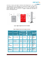
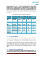
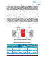
As for the total number of devices connected to the I2C bus is determined by the
maximum bus capacitance. According to I2C specification, a maximum bus
Solution Guide to I2C BUS Communication
Page 3