1
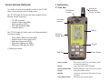
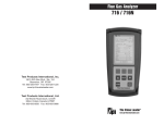
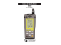
Indoor Air Quality Meter
1010
Rev. 2.x / 3.x Meters
The Value Leader
www.tpi-thevalueleader.com
TM
Contents
1.
Introduction
2.
General Overview
3.
3.1
3.2
3.3
Familiarization
Front View
Soft Keys
Back View
4.
4.1
4.2
4.3
4.4
4.5
4.6
4.7
Operation
Turning On & Off / Performing a Test / Main Display
Selecting Temperature Units
Ambient / Dew Point / Wet Bulb Temperature Display
Temperature / Clock Display Modes
Activating the Backlight
Setting Date and Time
Setting CO Alarm Level
5.
5.1
5.2
Calculating % Outside Air
% Outside Air (Temperature)
% Outside Air (Carbon Dioxide)
6.
Data Logging
7.
Retrieving Logged Data
8.
Technical Specifications
9.
9.1
9.2
Maintenance
Battery Replacement
Service
10.
Technical Information
1. Introduction
Thank you for purchasing TPI brand products. The TPI 1010 Indoor Air
Quality (IAQ) Meter is a state of the art, easy to use tester designed to
provide you with the necessary measurements to monitor and make
adjustments to air handling devices. The instrument is ruggedly constructed and comes with a 3 Year unit and 2 Year sensor Guarantee.
2. General Overview
The 1010 IAQ meter uses state of the art sensors to measure humidity,
carbon monoxide (CO), carbon dioxide (CO2), and temperature. The
CO and CO2 sensors in your meter will need to be replaced periodically
and calibration is recommended once every year.
The CO sensor is electrochemical and this type of sensor is always
active once installed in the unit. Therefore the time the unit is off and
not being used must be taken into account when determining sensor
life. The sensors in your analyzer are warranted for two years. This
warranty does not cover sensors damaged through misuse of the
meter.
You should keep battery power applied to your sensors at all times.
The following guidelines will help prevent damage to your sensors:
Always store your unit in a place where the temperature does not get
down to or below freezing.
Always maintain battery power to the sensors. When the batteries get
low replace them as soon as possible.
Never allow foreign objects or material to enter the sensor holes, damage to the sensor may result.
Never over saturate your sensors by performing tests on equipment
with gas levels beyond the capability of you analyzer.
General Overview (Continued)
3. Familiarization
3.1 Front View
This manual will guide you through the functions of the TPI 1010
which will give you many years of reliable service.
CO2 Sensor
Location
Humidity &
Temperature
Sensor Location
Your TPI 1010 Indoor Air Quality meter comes complete with the
following standard accessories:
•
•
•
•
•
TPI 1010 Instrument
Protective Rubber Boot (A800)
Soft Carrying Case (A921)
USB Cable & Software (A803)
Instruction Manual
Your TPI 1010 Indoor Air Quality meter has the following optional
accessories available:
•
•
•
•
•
CO Sensor
Location
Display
Protective
Rubber Boot
Power adapter / Battery eliminator (A804)
Magnetic strap kit to hang meter (A127)
Boot hook to hang meter (A103)
Replacement Software only (A802)
Replacement USB cable only (A801)
Keypad
( ) Denotes part number
Power Adapter
USB Port
Sensor Locations:
Places where the CO, CO2, and Humidity sensors
are located and protected.
Display :
Large 4 Parameter Backlit LCD Display.
Protective Rubber Boot
Provides protection to meter housing and sensors.
Keypad
Selects all available functions
USB Port
Location for connection of USB cable for PC com
munication.
Power Adapter Socket
Location to connect power adapter.
3.2 Soft Keys
3.3 Back View
On / Off key - Used to turn the IAQ meter on or off. Press to turn on,
press and hold to turn off.
Up Arrow key - Used to select and change parameters. Also used to
cycle through dew point and wet bulb temperatures from the main
display.
Left Arrow key - Used to select and change parameters.
Hanger Hole
Right Arrow key - Used to select and change parameters.
Down Arrow key - Used to select and change parameters.
Enter key - Used to activate % outside air mode. Also used to accept
parameter changes.
Mode key - Used to activate and deactivate data logging mode. Press
and hold to activate or deactivate logging.
Tilt Stand
Backlight key - Used to turn the display backlight on and off.
T/C key - Used to switch the bottom display between temperature /
humidity and time display modes.
Battery Cover Screw
Unit key - Used switch the bottom temperature display between
Fahrenheit and Celsius modes.
Hanger Hole:
Use to hang instrument for hands free operation. Can
be used with A127 magnetic strap kit or A103 hook.
Tilt Stand:
Use to stand instrument on a table.
Batter Cover
Screw:
Loosen this screw and open cover to access batteries.
4. Operation
4.2 Selecting Temperature Units
Pressing the
4.1 Turning On & Off / Performing a Test / Main Display
Always: - Turn the 1010 on outside of the area to be tested. Make sure the
unit is in fresh air (no carbon monoxide present) prior to turning on. This will
allow the CO sensor to set to zero properly.
key switches the temperature display between °F and °C.
4.3 Ambient / Dew Point / Wet Bulb Temperature Display
Repeatedly pressing the
key from the main display cycles through dew
point temperature, wet bulb temperature, and ambient temperature displays.
Press the
key and the 1010 will begin a 30 second countdown. During
this time the 1010 performs a self diagnostic and sets the CO sensor to zero.
Once the countdown ends the 1010 will display CO2, CO, Temperature, and
Humidity.
Enter the area to be tested, the measured values will be displayed.
Carbon dioxide (CO2) in parts per million (ppm) is displayed at the top, carbon monoxide (CO) in parts per million (ppm) is displayed in the middle,
temperature in °F or °C (selectable), and humidity in percent are displayed at
the bottom of the main display.
Ambient Temperature
Dew Point Temperature
Indicated by “DP” in the
display
Wet Bulb Temperature
Indicated by “WB” in
the display
4.4 Temperature / Clock Display Modes
The battery indicator is located at the bottom left of the display. When the
batteries become low they must be replaced to maintain proper operation.
Carbon dioxide (CO2)
Carbon monoxide (CO)
Battery indicator
To turn the 1010 off, press and hold the
Temperature
Humidity
key down until the 1010 turns off.
If 30ppm or more CO is measured the 1010 will beep and the display will
flash red as a warning. This alarm point is adjustable. Additional functions
can be activated during testing. Please see next sections.
Pressing the
key from the main display cycles between temperature
and clock display. To set the clock please refer to section 4.6.
4.5 Activating the Backlight
Pressing the
key turns the display backlight on and off. Power
consumption is much higher when the backlight is activated. The backlight
will automatically turn off 30 seconds after it is activated. To conserve battery life the backlight should only be used when necessary.
4.6 Setting Date and Time
4.7 Setting CO Alarm Level
1) Starting with the 1010 turned off, press and hold down the
press and hold down the
key then
The 1010 is equipped with an audible and visual alarm for carbon monoxide. The
alarm level is factory set at 30ppm. When CO above this level is measured, the
1010 will beep and the display will flash red.
key until two beeps are heard and the time / date
The alarm level is adjustable and can be set from 10ppm to 500ppm.
screen is displayed.
1) With the 1010 turned on, press and hold down the
until the CO alarm screen is displayed.
and
keys
Year
Month / Day
CO alarm level in ppm
Hour / Minutes
(24 hour clock, HH:MM)
2) Using the Arrow keys, set the year. Once the year is set, press
3) Using the Arrow keys, set the month. Once the month is set, press
4) Using the Arrow keys, set the day. Once the day is set, press
5) Using the Arrow keys, set the hour. Once the hour is set press
6) Using the Arrow keys set the minutes. Once minutes is set, press
The 1010 will return to normal operation.
Using the Arrow keys set the alarm point to the desired level. The
keys increase or decrease the value.
keys select the digit and the
key to return to normal
Once the desired alarm point is set, press the
operation.
5.2 % Outside Air (Carbon Dioxide)
5. Calculating % Outside Air
HVAC systems use a combination of outside air, supply air, and return air to maintain
consistent and comfortable air quality. The 1010 can calculate outside air either by
measuring temperature or by measuring CO2.
The formula used to calculate % outside air is:
key about 2 seconds until “t-0” is
To activate % outside air mode, press the
displayed in the middle display area. Press and hold the
key until “C-0” is
displayed.
1) Place the sensor of the 1010 perpendicular to the “Return” air flow. When the
reading stabilizes press the
key and capture the return air temperature,
"C-1" is displayed.
Percent outside air can be calculated using either temperature or carbon dioxide.
2) Place the sensor of the 1010 perpendicular to the “Supply” air flow. When the
reading stabilizes press the
key and capture the supply air temperature,
"C-2" is displayed.
5.1 % Outside Air (Temperature)
3) Place the sensor of the 1010 perpendicular to the “Outside” air flow. When the
reading stabilizes press the
key and capture the outside air temperature,
"C-3" is displayed.
To activate % outside air mode, press the
displayed in the middle display area.
key about 2 seconds until “t-0” is
1) Place the sensor of the 1010 perpendicular to the “Return” air flow. When the
reading stabilizes press the
key and capture the return air temperature,
"t-1" is displayed.
2) Place the sensor of the 1010 perpendicular to the “Supply” air flow. When the
reading stabilizes press the
key and capture the supply air temperature,
"t-2" is displayed.
3) Place the sensor of the 1010 perpendicular to the “Outside” air flow. When the
reading stabilizes press the
key and capture the outside air temperature,
"t-3" is displayed.
4) Press the
key, "t =" will be displayed and the calculated percent outside
air will be displayed at the top of the display.
5) If you want to perform this measurement again, press the
return to step 1.
key once and
6) To exit and return to normal operation, press and hold the
key until “C-0”
is displayed. Press and hold the
key until a beep is heard and the 1010
returns to normal operation.
4) Press the
key, "C =" will be displayed and the calculated percent outside
air will be displayed at the top of the display.
5) If you want to perform this measurement again, press the
return to step 1.
key once and
6) To exit and return to normal operation, press and hold the
a beep is heard and the 1010 returns to normal operation.
key until
6. Data Logging
7. Retrieving Logged Data
key until the logging setup
To activate data logging press and hold down the
screen is displayed. Once the logging function is activated all preciously logged
data is written over.
To retrieve logged data the USB cable and PC software (both supplied) must be
used.
Install the PC software on your PC and open it.
Connect the 1010 to the PC using the USB cable.
Click on the connect to PC button in the software window.
The software can be used to retrieve logged data and for real time monitoring.
COM port setting is:
1) INT is displayed at the top to indicate the 1010 is waiting for the logging interval
to be set. The logging interval tells the 1010 how often to sample. For example, a
logging interval of 10 seconds (00:10) means the 1010 will log a reading every
10 seconds. The bottom indicates the current logging interval in minutes and seconds (MM:SS) or hours and minutes (HH:MM). Flashing “SEC” in the display
indicates the last two digits are seconds and a flashing “MIN” in the display indicates the last two digits are minutes. In seconds mode the time is adjustable from
1 sec to 59 min 59 sec. In the minutes mode the time is adjustable from 1 min to
keys switches between the two time
23 hr 59 min. Pressing the
modes.
key and time digits will flash. Using
2) Once the time mode is set press the
the Arrow keys set the interval to the desired level. The
keys select the digit and the
keys increase or decrease the value.
3) Once the seconds have been entered, press the
key to move to min / hr.
4) Using the Arrow keys set the interval to the desired level. The
keys select the digit and the
keys increase or decrease the value.
key and the 1010 will return to
5) Once the logging interval is set press the
the main display and “LOG” will flash indicating the logging function is active.
6) To deactivate data logging press and hold down the
no longer flashing.
key until “LOG” is
For data retrieval please see the next section on how to retrieve logged data.
Baud rate: 19200
Parity: None
Data Bits: 8
Stop Bit: 1
8. Technical Specifications
9. Maintenance
Function
CO2
Range
Accuracy
0 to 5000ppm 50°F~104°F: ±3% of rdg+75ppm
<50°F, >104°F: ±5% of rdg+75ppm
Temperature
-5°F to 140°F ±2°F
-20°C to 60°C ±1°C
It is recommended that the instrument be calibrated every 12 months.
Please consult Test Products International for further details (800) 368-5719.
9.1 Battery Replacement
When the batteries become low they will require replacement.
Dew Point Temperature -47°F to 135°F Calculation
-44°C to 57°C
Wet Bulb Temperature
3°F to 135°F
Calculation
-16°C to 57°C
Relative Humidity
5% to 95%
±2% RH
CO
0 to 500ppm
±3ppm or ±5% of rdg whichever
is greater
% Outside Air
0 to 100%
Calculation
Data Logging: Up to 4,000 samples 1 sec to 23hr 59min interval.
Display Type: 3 line with annunciators and backlight
CO Alarm: Audible and visual, selectable level (factory default 30ppm)
Operating Temperature & Humidity
CO and CO2: 14°F to 122°F (-10°C to 50°C)
All Other Function: -4°F to 140°F (-20°C to 60°C)
Humidity 15 ~ 95% non-condensing
Storage Temperature: -4°F to 140°F (-20°C to 60°C)
Power supply
3 AA battery( 4.5V)
AC/DC adapter 5Vout (Center positive)
Battery Life: 40 hours typical without backlight
Output: Serial output via USB connection
1. Turn the meter over so the back is facing you.
2. Loosen the screw holding down the battery cover located under the tilt
stand.
3. Lift the tilt stand up and remove the battery cover.
4. Replace the batteries (3 x AA Alkaline) and install the cover and tighten the
screw.
9.2 Service
To obtain warranty and non-warranty performance or maintenance on your
analyzer: - Include with the product your name, address, phone number, written description of the problem and proof of purchase date. Carefully package
and return to:
TPI / Attn. Repair
9615 SW Allen Blvd. Suite 104
Beaverton, OR 97005
8. Technical Specifications
9. Maintenance
Function
CO2
Range
Accuracy
0 to 5000ppm 50°F~104°F: ±3% of rdg+75ppm
<50°F, >104°F: ±5% of rdg+75ppm
Temperature
-5°F to 140°F ±2°F
-20°C to 60°C ±1°C
It is recommended that the instrument be calibrated every 12 months.
Please consult Test Products International for further details (800) 368-5719.
9.1 Battery Replacement
When the batteries become low they will require replacement.
Dew Point Temperature -47°F to 135°F Calculation
-44°C to 57°C
Wet Bulb Temperature
3°F to 135°F
Calculation
-16°C to 57°C
Relative Humidity
5% to 95%
±2% RH
CO
0 to 500ppm
±3ppm or ±5% of rdg whichever
is greater
% Outside Air
0 to 100%
Calculation
Data Logging: Up to 10,000 samples 1 sec to 23hr 59min interval.
Display Type: 3 line with annunciators and backlight
CO Alarm: Audible and visual, selectable level (factory default 30ppm)
Operating Temperature & Humidity
CO and CO2: 14°F to 122°F (-10°C to 50°C)
All Other Function: -4°F to 140°F (-20°C to 60°C)
Humidity 15 ~ 95% non-condensing
Storage Temperature: -4°F to 140°F (-20°C to 60°C)
Power supply
3 AA battery( 4.5V)
AC/DC adapter 5Vout (Center positive)
Battery Life: 40 hours typical without backlight
Output: Serial output via USB connection
1. Turn the meter over so the back is facing you.
2. Loosen the screw holding down the battery cover located under the tilt
stand.
3. Lift the tilt stand up and remove the battery cover.
4. Replace the batteries (3 x AA Alkaline) and install the cover and tighten the
screw.
9.2 Service
To obtain warranty and non-warranty performance or maintenance on your
analyzer: - Include with the product your name, address, phone number, written description of the problem and proof of purchase date. Carefully package
and return to:
TPI / Attn. Repair
9615 SW Allen Blvd. Suite 104
Beaverton, OR 97005
10. Technical Information
10. Error Codes & Troubleshooting
CO2 Sensor Error
% Outside Air - HVAC systems use a combination of outside air, supply air, and
return air to maintain consistent and comfortable air quality. The 1010 can calculate outside air either by measuring temperature or by measuring CO2. The formula for % Outside Air is:
If too little outdoor air enters a home, pollutants can accumulate to levels that can
pose health and comfort concerns. Unless they are built with special mechanical
means of ventilation, homes that are designed and constructed to minimize the
amount of outdoor air that can 'leak' into and out of the home may have higher pollutant levels than other homes. However, because some weather conditions can
drastically reduce the amount of outdoor air that enters a home pollutants can build
up even in homes that are normally considered 'leaky'.
Dew Point Temperature - This is the temperature at which condensation begins
Wet Bulb Temperature - This is the lowest temperature evaporating water can
reach
Recommended Levels by Agency
Parameter
Humidity
IDPH1
20% - 60%
Temperature
68 - 75 (winter)
73 - 79 (summer)
Carbon Dioxide 1,000ppm
(<800ppm preferred)
Carbon Monoxide 9ppm
ASHRAE2
30% - 60%
OSHA PEL3 ACGIH TLV4
N/A
N/A
68 - 75 (winter)
N/A
73 - 79 (summer)
1,000ppm
5,000ppm
N/A
9ppm
25ppm
50ppm
5,000ppm
N/A-Not Applicable or Not Established
1
Illinois Department of Public Health (2009)
American Society of Heating, Refrigerating and Air Conditioning Engineers
3 Occupational Safety and Health Administration Permissible Exposure Limit -- this level
is a time-weighted average and is an enforceable standard that must not be exceeded
during any eight-hour work shift of a 40-hour work week.
4 American Conference of Governmental Industrial Hygienist Threshold Limit Value -- this
level is a recommended time-weighted average upper limit exposure concentration for a
normal eight to 10-hour workday and a 40-hour work week.
2
If the CO2 sensor fails to initialize or is faulty the
1010 will display an error code. Try turning the 1010
off and on again. If it displays the error code again
the 1010 is in need of service. Please return your
instrument to TPI. See section 9.2 for instructions on
returning your meter.
CO Sensor Error
If the CO sensor fails to initialize or is faulty the 1010
will display an error code. Try turning the 1010 off
and on again. If it displays the error code again the
1010 is in need of service. Please return your instrument to TPI. See section 9.2 for instructions on
returning your meter.
CO Sensor Caibration Due
When the last calibration date of the CO sensor is
one year or older the 1010 will display a reminder
that calibration is due before returning to normal
operation. Please return your instrument to TPI for
calibration. See section 9.2 for instructions on
returning your meter.
Temperature and/or Humidity Sensor Error
If the temperature and/or humidity sensor fails to initialize or is faulty the 1010 will display an error code.
Try turning the 1010 off and on again. If it displays
the error code again the 1010 is in need of service.
Please return your instrument to TPI. See section 9.2
for instructions on returning your meter.
Test Products International, Inc.
9615 SW Allen Blvd., Ste. 104
Beaverton, OR 97005
Tel: 503-520-9197 Fax: 503-520-1225
www.tpi-thevalueleader.com
Test Products International, Ltd.
342 Bronte Road South, Unit #9
Milton Ontario Canada L9T5B7
Tel: 905-693-8558 Fax: 905-693-0888