1
82 813 A801 GB
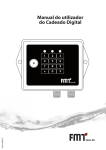
User Manual for Code Lock
G User Manual for Code Lock
Contents
1.
1.1.
1.2.
1.3.
1.4.
1.5.
2.
3.
4.
5.
6.
2
Display/control elements and their functions______________________________________________3
LED status display_____________________________________________________________________3
Keypad_ ____________________________________________________________________________3
Configuration________________________________________________________________________3
i-Button (optional)_ ___________________________________________________________________4
Electrical connections_ ________________________________________________________________4
Programming________________________________________________________________________5
Operation___________________________________________________________________________6
Hardware_ __________________________________________________________________________6
Repairs/service_______________________________________________________________________7
EC declaration of conformity____________________________________________________________7
User Manual for Code Lock G
1.
Display/control elements and their functions
The hardware is designed so that all LEDs are OFF, and the relay is de-energised.
1.1
LED status display
The device has three light emitting diodes (LEDs): red, yellow, and green. When the device is operational,
one of the three LEDs is always illuminated. If none of the LEDs is illuminated, the device has a fault.
The three LEDs indicate:
■■ Permanent red: Device fault, incorrect configuration/device not operational, or no PIN or i-Button
saved. Relay is de-energised.
Flashing red: Device is blocked because of incorrect entry or switch 4 has been set.
Short flashing red (200 ms): PIN or i-Button has been deleted
Long flashing red (1 s): All entries deleted.
■■ Permanent yellow: Successfully completed, valid entry process. Relay triggered/closed.
Short flashing yellow (200 ms): Keypad entry
Long flashing yellow (1 s): Confirmation that new PIN or Super-PIN has been activated
Rapid flashing yellow (approx. ¼ second rhythm for 5 s): Waiting for confirmation of “Delete all” in
programming mode.
■■ Permanent green: Base state, relay is de-energised.
Flashing green (approx. 1 second rhythm): Operational state during an incomplete entries of numbers
(PIN or Super-PIN for programming mode). At least one key was pressed, and other key presses are
expected, until the the entry process has been fully completed.
Rapid flashing green (approx. ¼ second rhythm): Programming mode is active, entry (PIN, Super-PIN)
or i-Button is expected.
1.2
Keypad
The numerical keypad is used to enter the sequence of numbers.
The * (DEL) key discards the entry or action and activates the base state. The relay de-energises/opens.
The # (ENTER) key is used for acknowledgement.
Key or i-Button entries (for programming or activation) are meaningful and possible only in the base state.
1.3
Configuration
There are four DIP switches on the printed circuit board; they are inaccessible from the outside.
DIP
Switch 1: ON – number entry (PIN) activated (standard)
Switch 2: ON – i-Button entry activated
ON WE
1 2 3 4
Switch 3: no function
Switch 4: ON – reset Super-PIN
3
G User Manual for Code Lock
If switch 1 and switch 2 are OFF (invalid setting), the red LED illuminates. This indicates possible corrosion
of the contacts.
If switch 4 is ON (reset of the Super-PIN to factory settings), all LEDs flash for approx. 1 second, and after
this the red LED flashes to indicate that switch 4 must be switched off again.
1.4
i-Button (optional)
The i-Button is used when only switch 2 is activated (ON).
If switch 1 and switch 2 are activated (ON), both number entry (PIN) and i-Button can be used.
1.5
Electrical connections
Attention!
The installer who carries out the electrical connection is responsible for complying with the applicable
directives and regulations.
Warning!
■■ When installing, and carrying out maintenance work, ensure that the power supply cables are not live.
■■ Always close the cover of the casing before reconnecting the power supply, after you have checked
the integrity of the seals which provide protection class IP 54.
Achtung!
Max. switching capacity 250 V AC / 8 A continuous / 10 A peak
4
User Manual for Code Lock G
2.
Programming
In the programming mode, the i-Button and PINs can be saved or deleted.
A list of maximum 96 i-Buttons and 96 PINs are supported. A freely selectable Super-PIN can be saved.
Programming is carried out from the base state (green LED ON, yellow LED OFF, relay de-energised) or in
the error state (red LED ON), if no PINs or i-Button are stored.
The programming mode is activated through the entry of a key sequence with a 6-place number
combination (Super-PIN). The programming mode is indicated by the rapid (¼ sec) flashing green LED;
invalid entries reset the device back to the base state.
The factory setting of the Super-PIN is:
# (ENTER) + 3 + 9 + 6 + 1 + 7 + 4 + # (ENTER) + * (DEL)
The number sequence of the factory setting is permanently stored in the device, and cannot be modified.
The Super-PIN can be modified (see below) and thus invalidates the factory setting.
The factory setting can be reactivated by means of switch 4 = ON. This does not delete the stored i-Button
and PIN list.
During entry, the green LED starts to flash in 1 second rhythm, and the yellow LED illuminates briefly for
each key pressed (approx. 200 ms).
The Super-PIN can be modified. For this, as when activating the programming mode, the full key sequence
is: to be entered with a new 6-place number combination, for example:
# (ENTER) + 9 + 8 + 7 + 6 + 5 + 4 + # (ENTER) + * (DEL)
If the programming mode is active (green LED flashes rapidly), then after entering a 4-place number
combination or making contact with the i-Button, this PIN or i-Button can be:
■■
saved by pressing # (ENTER). The yellow LED illuminates for approx. 1 sec. If the PIN or i-Button already
exists, the yellow LED does not illuminate.
■■
deleted by pressing * (DELETE). The red LED illuminates briefly for 200 ms. If the PIN or i-Button does
not already exist, the red LED does not illuminate.
■■
If * (DEL) is pressed continuously, i.e. for approx. 2 sec, all PINs and i-Buttons can be deleted. The yellow
LED changes to rapid flashing, and requires confirmation by pressing # (ENTER) within approx. 5 sec.
Upon confirmation, the red LED illuminates for approx. 1 second, thereby indicating deletion.
■■
■■
■■
■■
Program the time for automatic de-energisation of relay
Press down a key between 0 and 9 for 2 seconds
Release the key
Yellow LED illuminates for approx. 1 second (programming OK)
Key
Programmed relay de-energisation time
0
1
2
3
4
5
6
7
8
9
No limit (manual de-energisation)
05 sec.
15 sec.
30 sec.
60 sec.
03 min.
05 min.
10 min.
15 min.
30 min.
5
G User Manual for Code Lock
The programming mode is exited or a PIN entry is rejected by entering * (DEL).
The programming mode is exited automatically if no entry is made within 60 seconds.
If no key is pressed for 30 seconds during the PIN entry, the entries so far are rejected and the green
LED flashes again. If there is no entry within another 30 seconds, the programming mode is exited as
described above, and the device changes to the base state (green LED illuminates, relay is de-energised).
3.
Operation
When the device is switched on, it is in the base state; the green LED is illuminated and the relay is deenergised.
If the i-Button is active (switch 2: ON), when contact is made with the i-Button, its validity is checked. Only
then is release indicated by means of the yellow LED. The green LED integrated into the i-Button flashes
briefly in 1 second rhythm to indicate its operational state.
If an i-Button in the recess of the reader is pressed, the yellow LED illuminates briefly to indicate that
reading has been carried out. In this case, the reader is blocked for approx. 6 seconds; this is sufficient time
to remove the i-Button from the reader again.
If the PIN is activated (switch 1: ON) the release is achieved through entry of a 4-place code.
In this case, a 4-place number can be entered in the base state (green LED is illuminated).
During the entry, the green LED flashes in 1 second rhythm.
When the entry is complete (4 numbers), and the number is identical to the internally saved PIN, the
yellow LED illuminates, and the relay is energised.
If no entry is made within 30 seconds, the device automatically returns to the base state, and the green
LED is again illuminated. Using * (DEL), entry of a number can be interrupted; the green LED is again
permanently illuminated in the base state.
In the case of an incorrect entry or an invalid i-Button, the device flashes red for approx. 3 seconds, and
then returns back to the base state.
If 5 incorrect PINs are entered consecutively, the device is blocked for 10 minutes, and it displays a flashing
red LED. This is intended to avoid that PINs can be ascertained through repeated entry attempts.
If there is an invalid i-Button, there is no count of attempts, and the device does not block. This is because,
in contrast to the entry of PINs, there is no possibility of unlimited numbers of attempts.
4.
Hardware
■■
■■
■■
■■
■■
■■
■■
■■
■■
■■
6
Dimensions of printed circuit board approx. 80 x 100 mm
Twin-terminal fuse protection
Twin-terminal switching contacts
Radio interference suppression on the relay contacts
Max. switching capacity 250 V AC / 8 A continuous / 10 A peak
Keypad: 10-key block with 2 special keys * (DEL) and # (ENTER)
3 LEDs for operational display (red, yellow, green)
Optional i-Button
Set of 4 DIP switches for configuration
Wide temperature range: +40 to -40 °C
User Manual for Code Lock G
5.
Repairs/service
The code lock has been developed and manufactured according to the highest quality standards. Should
a problem occur in spite of all quality measures, please contact our service department:
FMT Swiss AG
Tel. +49 9462 17-216
Fax +49 9462 1063
[email protected]
6.
EC declaration of conformity
We hereby state that the appliance described below, in the model which we have made commercially
available, complies in its design and construction with the EU directives. If a change has been to the
appliance, and this has not been agreed with us, this statement loses its validity.
Designation of device
code lock
Device type
code lock
Baujahr
siehe Typenschild
Applicable EC directives
EC Low Voltage directive (73/23/EEC)
EC Electromagnetic Compatibility (89/336/EEC)
subsequently 93/31/EEC
Applied national standards
DIN VDE 0843 T1
30 June 2012
FMT Swiss AG
Dipl.-Ing. Rudolf Schlenker
7
FMT Swiss AG
Fluid Management Technologies Swiss AG
Gewerbestraße 6
6330 Cham / Schweiz
Tel. +41 41 712 05 37
Fax +41 41 720 26 21
[email protected]
www.fmtag.ch