1
AUV + WaveGlider communication scenarios
Frédéric Py, Tom O’Reilly, Kanna Rajan
Original:February 11, 2013::Revised: March 21
1
Problem Definition
We try here to explore how the WaveGlider could be used as a communication
relay between deployed AUV(s) and the shore or a ship. The general idea is
to replace the expensive — either financially or in term of energy required
— and limited — iridium satellite connections with a more pervasive data
point. While ideally the WaveGlider could be always connected to the shore
(using for example a wireless data plan to send data as it come though)
it is probably more realistic in general to consider it more as a proxy that
stores data from an AUV operating nearby until it is connects to the wider
world. In such a case, on connecting to the net, it can flush whatever data is
currently cached (using for example some sort of rsync mechanism between
its data and the shore).
The usage of the WaveGlider will be often considered in our scenario
as bi-directional where not only messages from an AUV but also new objectives/missions from shore to it will transit through the WaveGlider. While it
may not be efficient in some cases and make for a brittle network1 , it simplifies
many considerations at this stage and specifically ensure that WaveGlider is
aware of what the AUV is supposed to do.
Our general problem can be defined as follows: (How) can we use the
WaveGlider as a means to improve communication between the shore and
AUV(s) deployed? This of course while ensuring better results than ad-hoc
communication using a satellite connection. Possible communication schemes
available on the AUV are limited in term of their range, their bandwidth or
the condition they can be used (most radio communication cannot be used
1
Indeed a failure of any point with the WaveGlider results on no communication at all
1
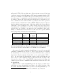
underwater). Table 1 shows what some of these systems can provide in term
of e↵ective average bandwidth during a AUV mission assuming that the AUV
surfaces for 1 minute every half hour. It is clear that there is a tradeo↵ between the range of communication and the amount of data that can be sent
in an hour. In fact the only technology that would be reasonable for remote communication are either satellite or possibly for near shore operation
wireless network communication such as EDGE. Which both due to the fact
that the vehicle is underwater most of the time exhibits the lowest e↵ective
bandwidth2 . These techniques do not allow sending very large data sets for
long missions in a sustainable way. It is also worth noting that all the data
presented here are idealistic; our experience has demonstrated that establishing a communication from an AUV in calm seas can be pretty difficult
thereby impacting even these theoretical findings.
Iridium
Freewave
EDGE (max)
EvoLogics 18/34
EvoLogics 48/78
Bandwidth
(kbps)
2.4
115
59.2
up to 13.9
up to 31.2
AUV e↵ective (kbph)
278.7
18000
6874.8
48425.8
108696.8
Limitations
surface
surface, 2km
surface, near coast
medium range, 3.5km
shallow, 1-2km
Table 1: Bandwidths from di↵erent communication possible on the AUV.
The AUV is e↵ectively at the surface for 1 minute every 30 minutes.
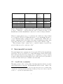
One expected benefit of using the WaveGlider is to provide a proxy with
permanent communication to the shore. Table 2 gives a picture on how using
the WaveGlider as a dedicated proxy between AUV and shore positively
impacts the e↵ective amount of data that can be sent from the AUV to
shore. By just having the WaveGlider equipped with an Iridium modem
and be able to connect with the vehicle by any other means, we improve the
data rate by a factor of 30. Using EDGE connection instead is then only
bounded by the e↵ective communication bandwidth between the AUV and
the WaveGlider.
While acoustic comms with EDGE presents the largest potential bandwidth this can vary substantially depending on the relative position of the
two assets. In addition this technology can be very energy intensive (5 – 35
2
It is also the 2 technologies that have a direct financial cost per data sent
2
AUV to WG (kbph)
Freewave + Iridium
Freewave + EDGE
Evo 18/34 + Iridium
Evo 18/34 + EDGE
Evo 48/78 + Iridium
Evo 48/78 + EDGE
18000
18000
48425.8
48425.8
108696.8
108696.8
WG
to
shore
(kbph)
8640
213120
8640
213120
8640
213120
E↵ective
8640
18000
8640
48425.8
8640
108696.8
Table 2: Bandwidth for comms from an AUV to WaveGlider and WaveGlider
to shore. “E↵ective” considers that the AUV is always in range of the
WaveGlider and that WaveGlider connection to shore is always available.
Watts for signal emission in good conditions and a little more than 1 Watt
for reception). Therefore I think that most of our experiments should be
covered efficiently using a simple freewave communication. While this constrains communication at the surface the range is usually larger than other
approaches and the power consumption is better (often 5 Watts or less).
Even though acoustic comms can be considered further down the line
provided that we need to send more data3 .
2
Incremental scenario
The main limitation in communication between the AUV and the WaveGlider
is its range. We propose therefore, to start with simple scenarios that ensure
that each asset stays in near-proximity and to eventually go to more complex
scenarios with rendezvous points which can be either pre-decided (in term of
location and time window) or identified autonomously.
2.1
WaveGlider as master
This first scenario relies on the drifter following missions already executed
with T-REX in the recent past. The WaveGlider will act as the “drifter” and
3
A quick look at the data we sent so far along with extrapolation based on 1Hz sending
of basic sensor data suggests that 8640 kbph (or 1MB per hour) is more than enough and
would be too expensive though Iridium anyway
3
the AUV will follow it by moving around it within a reasonable range (1km
or so).
At first the WaveGlider can just act as a communication relay and the
construction of a new goal for the AUV is still done on shore based on
WaveGlider position and speed. This allow testing how much communication
can be done without having to take into account the risk of not having the
assets in range.
We can then refine it further by setting WaveGlider as an active master as
it redirects the AUV autonomously without shore involvement and continues
to send all the contextual data from the AUV to shore. Further one can
picture to simply redirect the WaveGlider which will result on the AUV
following it without need of reconfiguration.
2.2
AUV as master
This scenario can be tricky as the WaveGlider is slower than the AUV. Which
mean that it cannot keep up on the AUV on a straight line. Therefore the
WaveGlider should find the best shortcut to be close enough to the AUV on
a future time.
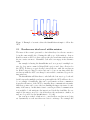
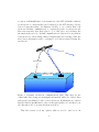
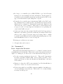
One proposed scenario relies on the AUV doing a lawnmower pattern and
the WaveGlider trying to find a next location to go to using this pattern,
where it can arrive before the AUV and wait for it to surface as illustrated
in Fig. 1. This scenario adds complexity on both sides; in order to decide its
next waypoint the WaveGlider needs to know what is the likely future path
of the vehicle in a reasonable time. Conversely the AUV may surface outside
of the comm range of the WaveGlider (for example in the northern part of
our lawnmower in Fig. 1) and needs to keep this data for next potential
window.
This scenario does not ensure constant communication between the two
assets and becomes more challenging as the AUV survey becomes closer
to a straight line. This may require exploring some coverage planning of
the WaveGlider which uses the AUV projected path to compute the best
trajectory to follow in order to ensure the best communication coverage along
the mission. This makes it even more chalenging when the AUV path is not
known a priori.
4
WG
AUV
WG wait for AUV
Figure 1: Example of scenario where the WaveGlider attempt to follow the
AUV
2.3
Rendezvous interleaved within mission
The issue of the scenario presented so far is that they force the two assets to
be in the same neighborhood during the full scope of the mission. A more
flexible scenario would be to have only specific places and time windows where
the two assets can meet. Meanwhile each asset can engage in its alternate
tasks.
An example is having the WaveGlider used as a proxy for multiple assets (eg deep water comm for Brian Keift’s project and data collection for
the AUV). It then goes periodically between the two with the rendezvous
for Keift being at a fixed location but can be done at any time while the
rendezvous with the AUV can change location while constrained by periodic
time windows.
The WaveGlider will then have to schedulle the best way to go back and
forth between the multiple rendezvous points while the AUV will have also to
do accordingly. Scientifically, this can be problematic as these communications alter the survey of the AUV by inserting these communication transits.
Still these points can be set so they are limiting the impact in term of continuity of the survey. As this first scenario consider predfeined communication
it is usefull to both anticipate the impact and check the feasibility (for example if the survey area is too far from where the underwater comm is, it
may not be posible for the WaveGlider to do both).
An even more refined solution is to consider these rendezvous as being
set dynamically as each asset has new data to exchange. For example the
5
reception of theWaveGlider of a new mission for the AUV will make it initiate
a rendezvous or conversely this can be intiated by the AUV having collected
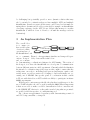
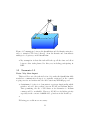
data it deems interesting. As illustrated in Fig. 2, we consider that both
assets use Iridium communication to organize/negotiate a rendezvous and
then autonomously alter their plan to go to this place and exchange the
information they need to. Iridum communication is only used for negotiation
between the two assets which ensures a lightweight data exchange while the
more heavy information will be exchanged on a faster netwrok during the
rendezvous.
WG to shore
RDV (lighweight)
Direct comm (~1km)
Figure 2: Dynamic rendezvous communications path. Blue lines are the
comm links that transport meaningful information while the dashed lines
indicate the data link used only to set a rendezvous. In this figure we consider
that the link for WaveGlider to shore is through satellite, it could have been
also through a 2G or 3g network when near shore.
This last scenario is in my opinion what we need to aim for it can
6
be challenging but potentially provide a more dynamic solution that may
also be extended to a situation where we have multiple AUVs and multiple
WaveGliders. In such a scenario all the assets could be used as data mule ensuring then a dynamic mobile ad-hoc network (for example one WaveGlider
A reciving a message for the AUV B can delegate this message to another
WaveGlider C which is closer to B and so on until the message reach its
destination).
3
An Implementation Plan
The overall idea
is to ensure we
Scenario 1.5
Scenario 0
Scenario 2
Scenario 3
have a viable plan
Scenario 1
of action to make
Scenario 0.5
Scenario 0.25
operational use of
the WaveGlider both
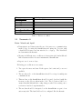
as a communi- Figure 3: An approximate timeline and temporal depencations ’hotspot’ dency between the tasks below.
and as a means
for demonstrating coordination techniques for AI Planning. The notion of
the hotspot, is to have the WaveGlider as a focal point of communication
between di↵erent assets in a field experiment. Currently while the Doradois
the intended coordination target, the steps we take ought to ensure that the
architecture can scale to including heterogenous (underwater, surface and
aerial) assets, as well as assets not belonging to and traditionally not operating out of MBARI. One specific point of coordination in this context
is UPorto with their Seacon AUVs which are likely to participate in future
CANON experiments.
With regard to autonomy specifically, the plan here is with respect to the
use of T-REX whether onboard or on shore using the ODSS. What is important
is that we are able to make a credible demonstration both to ourselves and
to the MBARI MT, that we’re on the path towards doing what we promised
we would for 2013 irrespective of constraints imposed.
Fig. 3 shows an approximate dependency with demonstrating scenario 0
and 0.25 being somewhat co-temporal.
7
Date
April 10 and 26
June 12th
July 11th
Aug 26th
Sept 4th
Oct 10th , 14th , 17th , 21st
Dec 17th
Activity
Request to DMO to postpone
Table 3: Table to be filled
3.1
Secenario 0
Dates: March end, April
• Demonstrate and characterize the use of freewave as a communication
methodology by using the WaveGlider and using the Paragon with
a hand-held freewave modem attached to a laptop. The hand-held
modem mimics the Dorado.
• Measure in di↵erent wave conditions to characterize the bandwidth and
link robustness with a freewave instrumented WaveGlider.
• Repeat over 2 or more days.
Following preconditions are necessary:
1. Two spare freewave modems. If the spares don’t exist and/or are not
available
2. The modem radio on the WaveGlider should be set up for multipoint
communications.
3. This modem on the WaveGlider should be tested (on shore) with the
freewave on the Carson when in the dock. The objective would be to
ensure that this link with the config change works before setting out to
sea in more involved experimentation.
4. The modem should be integrated on the WaveGlider as part of an
autonomy task. The hand-held radio is configured like the Dorado.
8
3.2
Secenario 0.25
Dates: March thru April
• Work co-temporally with the task in Section 3.1
• Demonstrate that a freewave modem on shore can talk to the WaveGlider
in near proximity. Test using Tom’s office with an antenna nearby.
Drive the WaveGlider from WGMS and perform experiments in distance from shore antenna and di↵erent environmental conditions.
• Build on this to use the shore-based SMC to write the freewave driver.
See Section 3.3 below.
• Configure the freewave radio in multipoint mode to make sure it works
with the WaveGlider at sea.
Following preconditions are necessary:
1. A suitable antenna can be found and rigged near by Tom’s office (or
some other convenient location facing the beach).
2. Proficiency of WGMS since more than likely the WaveGlider will be
close to ship traffic from Moss Landing.
3. Suitable understanding of the C&C API.
3.3
Secenario 0.5
Dates: April and May
• Use the SMC (Sensor Mgmt. Computer) to demonstrate an SMC/C&C
(Command and Control computer) client server applicability.
• WaveGlider ICD documents apparently shows the API to talk directly
to the C&C. We should use this API first as a simple stand alone app to
send lat/long from Tom’s office to the WaveGlider. Then consider its
integration into a UI within ODSS so people can pilot it outside T-REX
control.
9
• In doing so, we initially rely on LRIs WGMS to get back all status
messages (see user manual) and state information. In subsequent development, we incrementally return state updates from the C&C to the
app, even if this means it just dumps into a log file.
• Doing the above, sets the stage for interfacing T-REX to the C&C, sending commands and receiving updates. Specifically the update mechanism should be configured to ensure that not just task completion, but
other state info can be returned. This would be critical when and if
we propose work on doing diagnostic information for re-planning and
control with T-REX onboard.
• At the very least state info returned should include lat/long, status of
umbilical to sub-surface glider and weather info from mast. If the radar
reflector can be tapped for target range and bearing, that too might
be useful for informational and potential path planning purposes even
if the WaveGlider is slow to react and respond.
Following preconditions are necessary:
1. Adequate time and resources
3.4
Secenario 1
Dates: August thru December
Demonstrate the first simple interaction of ’coordinated’ activity between
a WaveGlider and the Dorado. This is the baseline demonstration that we
ought to be aiming for, for 2013 based on the internal autonomy proposal.
• Use the scenarios starting in Section 2.1. This would demonstrate
modeling capabilities within T-REX on shore which can make coarsegrained predictions on where the Dorado and WaveGlider could meet
on the surface.
• Migrate to where the AUV is unconstrained and the WaveGlider is
expected to ’arrive’ at a location as in Section .
• Work closely with Porto and LRI to integrate multiple data link protocols and switching between the two. This would be a core functionality
necessary for this project.
10
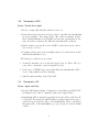
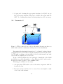
Iridium
ODSS
Wave Glider
Freewave
Figure 4: Communicate between the WaveGlider and the Dorado using freewave to transfer CTD data (others?) from the Dorado and demonstrate
multi-protocol gateway on the WaveGlider.
• My assumption is that this task will take up all the time and e↵ort
between other tasks planned for this year, including participating in
REP.
3.5
Secenario 1.5
Dates: May thru August
This is a follow on to the task in Section 3.2 to make the WaveGlider fully
standalone communication hotspot as originally envisioned in the comms
scoping exercise and written into the 2013 autonomy MBARI proposal.
• A minimum objective is to demonstrate a gateway functionality which
switches onboard data packets between 3G/4G and Iridium Rudics.
Time permitting, the use of Globalstar as an alternative to Iridium
comms would be worthwhile. However, 3G/4G is a far higher priority
especially in the context of CANON field operations in the north bay.
•
Following preconditions are necessary:
11
1. Scoping and obtaining the appropriate hardware for 3G/4G. As per
Robert’s message LRI has “integrated a COTS cell modem with the
SMC”. So obtaining this software and integrating it would be necessary.
3.6
Secenario 2
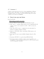
Iridium
Globalstar/SPOT
ODSS
Drifter
Freewave
Wave Glider
CTD
Drogue
Figure 5: CTD is connected via a cable to the surface freewave modem on a
Stella drifter which is continuously sending data to the WaveGlider.
Demonstrate the first simple interaction of ’coordinated’ activity between
a WaveGlider and a stella drifter, with the WaveGlider following the drifter.
A CTD with a real-time readout will be hooked to the freewave and send
data at the set sampling rate of the CTD.
Doing so will demonstrate the basic principles of mutability of the T-REX
model from one vehicle (Dorado) to a very di↵erent vehicle on the surface.
It will add another potent tool set for CANON science.
Following preconditions are necessary:
1. An appropriate CTD with a cable to the surface expression with the
freewave modem.
2. Freewave modem would need to be encased in a water-tight box with
a lead out for the antenna.
12
3.7
Secenario 3
Combine scenarios in Sections 3.6 and 3.4, to have a WaveGlider and Dorado
moving around a stella drifter. It is unclear whether this scenario can be
demonstrated given a lot depends on the smooth functioning and execution
of all the above scenarios as a minimum.
4
Near-term ops and ideas
From Tom O’Reilly:
Tasks leading up to April 17 deployment:
1. Integrate FGR2 and antenna with WG/SMC [Maughan, Coenen]
2. Setup ”testnode” consisting of FGR2/antenna connected with Linux/MacOS
computer; testnode acts as stand-in for AUV or UAV in early tests
[O’Reilly]
3. Setup onshore WG-to-testnode communications test environment (e.g.
in high bay?) [Cha↵ey, Maughan, O’Reilly]
4. Ramp up on WG SMC software environment, FGR2 interfaces and
APIs [O’Reilly]
5. Refine April 17 hot spot scenarios [OReilly, Maughan, Rajan, Py, Chaffey]
6. Demonstrate WG SMC code update through FGR2 [O’Reilly]
7. Demonstrate transfer of simulated ”mission script” from WG to test
node, simulated ”telemetry” transfer from test node to WG. Use rsync/scp/ssh
or DTN as appropriate. [O’Reilly]
13
4.1
2013 OReilly Ocean Hotspot software tasks
Evaluate hotspot approach +
Implement WG file sync
Integrate cell modem with PPP/SLIP
Support scenario 1.5
Get familiar +
Configure Freewave modems
with PPP/SLIP +
Support April WG-shore-Paragon tests
Software integration of CTD with
Freewave for Stella drifter
Support scenario 2
CANON Fall
expt. including Porto AUVs
Abstracts due
Proposals due
May
June 25th
April
Target date: 15th
Target date: 17th
June
Target date: 1st
Aug
July/Aug
Sept
Target date: 16th
Figure 6: Suggested timeline of work based on Tom O’Reilly’s task list. Note
the temporal location of the drifter/tracking experiment prior to full MBARI
proposals due.
Here is additional detail in terms of what Tom considers needs to be done
in terms of Comm Hotspots from his end. Note that tasks are not yet ordered
within a given priority level. Fig. 6 visualizes the timeline.
1. Get familiar with WG onboard software development environment (5
days)
2. Configure Freewave modems on WG and test node with PPP or SLIP
Presumes that Maughan handles electrical/mechanical integration (1
day)
3. Support April WG-shore-Paragon tests; includes pre-deployment test
support. Presume that Cha↵ey/Maughan handle electrical/mechanical
issues. Supports Scenario 0.25. (10 days)
4. Integrate cell modem with PPP or SLIP Presume that Cha↵ey/Maughan
handle electrical/mechanical integration Supports Scenario 1.5. (1 day)
5. Evaluate hotspot infrastructure approach (rsync/ssh vs DTN) Present
rationales and trade-o↵s to team (5 days)
14
6. Implement WG file sync with test box via TCP/IP, rsync over Freewave
(2 days)
7. Implement WG file sync with shore via TCP/IP, rsync over Rudics or
cell modem (2 days)
8. Support Fall CANON 2013 Hotspot operations (10 days)
9. 6/25/2013 - Project abstracts due
10. Software integration of CTD with Freewave for Stella drifter experiment Presume Cha↵ey/Maughan handle mechanical/electrical integration Supports Scenario 2. (5 days)
11. Support Fall CANON 2013 Hotspot operations (10 days)
Lower priority 2013 tasks
1. Integrate Globalstar modem with PPP or SLIP Presume Cha↵ey/Maughan
handle mechanical/electrical integration
2. Implement autonomous WG comms channel selection
Open questions:
1. What kind of antenna should testnode have?
2. RF safety issues with these radios/antennas?
15