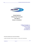
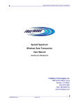
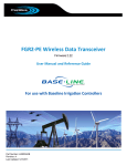
1
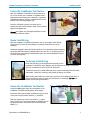
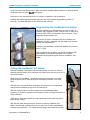
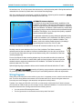
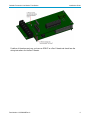
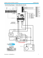
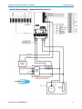
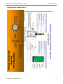
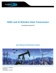
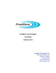
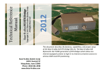
Cathodic Protection LineMarker Test Station Installation Guide Applies To the following FreeWave Products • • • FGR-CP FGR2-CP GX-CP For additional information about the Cathodic Protection (CP) radios and for Modbus register map information, see the Cathodic Protection User Manual Addendum available at www.freewave.com and on the User Manual and System Tools CD. Required Tools and Supplies Installation of the FreeWave model LineMarker Test Station requires the following tools and supplies: 1. 2. 3. 4. 5. 6. Phillips screw driver Standard screw driver Wire stripping pliers Spare insulated copper wire (Optional ) Cordless or corded drill with screwdriver bits (Optional) Nylon wire ties 3 Inch Conduit Installation The 3 inch, schedule 40, cathodic protection conduit should extend 24 to 36 inches above ground level, to provide sufficient ground clearance for snow build up or the potential growth of ground vegetation. The 3 inch conduit should be buried below grade 24 to 48 inches to provide sufficient structural integrity for the LineMarker Test Station installation. Cementing the 3 inch conduit in place is not required, but recommended to improve the lateral rigidity of the complete installation. Part Number: LIG0008AB Revision: A Last Updated: 11/14/2011 www.freewave.com 866.923.6168 303.381.9200 Cathodic Protection Line Marker Test Station Installation Guide Open the LineMarker Test Station Enclosure Using a Phillips screw driver or cordless drill with Phillips screw bit, turn the 4 fasteners counterclockwise from the base of the LineMarker Test Station. Be careful not to drop the fasteners, storing them in a secure location for reassembly later. Carefully, lift the top of the LineMarker Test Station enclosure vertically until the bottom of the enclosure clears the top of the CP radio green boards. The solar power panel wires and corresponding termination connector should now be exposed. Using one hand to hold the enclosure top in place, use a small standard blade screw driver to unfasten the two retaining screws in the side of the solar panel power termination connector, releasing it from its corresponding fixed connector on the CP radio board. At this point pull the two connector halves apart. With the two connector halves separated, you can slide the LineMarker Test Station enclosure top vertically until the enclosure top and solar power panel wires are clear of the radio and antennae assembly. Set the enclosure top aside, facing the solar panel up to prevent surrounding surfaces from damaging the solar panel surface. Install the LineMarker Test Station With a 3 inch plastic conduit in place and field wiring already run, slide the LineMarker Test Station over the top of the conduit, while running the field wiring up through the wire access hole in the bottom of the LineMarker Test Station base plate assembly. Firmly push down on the base plate assembly until the base adapter cap securely sits on top of the 3 inch conduit. Field wiring should be free of any kinks or binding against the 3 inch conduit or the LineMarker Test Station. Point the Solar Panel South Rotate the LineMarker Test Station on top of the 3 inch conduit until the solar panel attached to the LineMarker Test Station is facing due south to maximize exposure of the solar panel to the sun. FreeWave does not recommend pointing the solar panel east or west, as this decreases solar exposure, which adversely affects the performance of the LineMarker Test Station. Part Number: LIG0008AB Rev A 2 Cathodic Protection Line Marker Test Station Installation Guide Fasten the LineMarker Test Station With the LineMarker Test Station firmly positioned on the 3 inch conduit, use a cordless or corded drill and appropriate screw driving bits to install the 4 provided self-tapping fasteners into the 4 predrilled holes in the bottom of the mounting adapter cap. Drive the self-tapping screws into place until no threads are seen and the fastener head is firmly seated against the adapter cap. Do not over tighten the self-tapping fasteners, as this may result in fastener failure. Route Field Wiring With the LineMarker Test Station fastened to the 3 inch conduit, route all field wiring from the bottom of the assembly up vertically towards the top of the assembly. FreeWave suggests looping all field wiring with a 6 inch diameter loop and securing the wiring behind the factory-installed black nylon wire ties, or optionally securing the field wiring to the factory-installed black nylon wire ties using additional nylon wire ties (not supplied). Terminate Field Wiring Route the field wiring to the appropriate terminals per the LineMarker Test Station wiring diagram, cut the field wires to length, and remove 3/8 inch of insulation from the ends of all field wires. Thread the screws to be used sufficiently open to pass the stripped field wire ends underneath. Avoid fully removing, and possibly dropping, the screws. While holding each field wire in place with one hand, use a Phillips screw driver to tighten the terminal screw counter until the fastener is hand tight. Do not over tighten the fastener. Complete all field wiring terminations. Power the LineMarker Test Station Locate the red copper power wire originating on the LineMarker Test Station dual battery power supply. Disconnect both slide-pronged termination lugs from both of the power supply battery positive (+) terminals. Slide the stripped end of the red, positive (+) copper power supply wire into the appropriate termination port on the green connector terminal on the CP board labeled Battery (+). Part Number: LIG0008AB Rev A 3 Cathodic Protection Line Marker Test Station Installation Guide Using one hand to hold the red wire in place, use a small standard blade screwdriver to securely tighten the terminal screw in place. Do not over tighten. Gently pull on the now-secured red wire to ensure it is captured in the terminal port. Reattach both slide pronged termination lugs onto their original power supply battery positive (+) terminals. The three LED lights on the CP radio should now be lit. Programming the LineMarker Test Station Using the FreeWave user documentation for your CP radio, a computer and programming cable, connect to the CP radio using the white 9-Pin, RS232 Communication Port or the gray, 20-pin, Diagnostics Communication Port. Program the CP radio in accordance with the FreeWave user manual for the radio, compatibly with the Master radio network settings and configurations. In menu 1 (Set Baud Rate), submenu B (ModBus RTU) must be set to “1” (ON). When programming is complete, and the CP radio display LED lights indicate it is linked and connected to the network, disconnect the programming cable from the LineMarker Test Station. Closing the LineMarker Test Station Slide the LineMarker Test Station enclosure top assembly over the top of the CP antennae until the bottom of the enclosure top is about even with the top of the CP radio green boards. While holding the LineMarker Test Station enclosure top assembly in one hand, grasp the green, two-pin solar panel power termination connector in the other hand. Push the green solar panel power termination connector into the corresponding fixed connector located at the top of the CP radio board. With the connector halves now firmly seated, use a small standard blade screwdriver to thread in, clockwise, both connector screws to ensure the halves are firmly reattached. Gently pull on both wires together and then separately to ensure the solar panel power wiring is secure. With the solar panel facing due south, continue to slide the LineMarker Test Station enclosure top vertically down over the rest of the CP radio, dual batteries, and base mounting flange. The 4 base mounting flange holes should line up with Part Number: LIG0008AB Rev A 4 Cathodic Protection Line Marker Test Station Installation Guide the enclosure top. If not, fully remove the enclosure top, confirm the solar panel is facing due south and reassemble the enclosure top back down onto the base mounting flange. With the 4 mounting holes now aligned, reinstall the 4 fasteners, tightening with a screwdriver. Do not over tighten the fasteners as this can damage the enclosure top. ALTERNATE Antennae Options To enhance the long range communication capabilities of the LineMarker Test Station, optional long distance and/or high gain antennae equipment may be selected and installed in conjunction with the LineMarker Test Station. Optional antenna, coaxial cable, and lightning surge protection devices can be purchased through FreeWave Technologies, Inc or through other quality, reputable wireless communication suppliers. To implement enhanced long range antennae equipment during or after the installation of the LineMarker Test Station, with the enclosure top removed from the installed LineMarker Test Station, remove the existing flexible antenna by threading it counterclockwise from the top of the CP radio. You may now attach a coax cable to the CP radio RF connector located on top of the radio. Carefully route the coax cable down the front of the LineMarker Test Station assembly optionally securing the coax cable to the factory-installed black nylon wire ties, and continue to route the coax cable down through the wire access routing hole in the bottom of the base mounting adapter cap. From a point below the base mounting adapter cap, the coax cable can either be routed out the side of the 3 inch conduit or routed below grade and back up above grade to the optional elevated antennae equipment located above the LineMarker Test Station and secured to the antennae mast every 3 to 4 feet. Optional lightning surge protection devices can be located and fastened behind the CP radio. FreeWave strongly recom m ends grounding all lightning surge protection equipment separate from the CP grounding system to an external ground rod per local building electrical codes and requirements. Wiring Diagrams When wiring a CP transceiver to the rectifier at your site, it is important to note on which board the radio is built. There are wiring differences between a Rev D board and a Rev E board. Wiring the transceiver incorrectly can cause damage to the transceiver and present a safety hazard. Typically, if you have an FGR2-CP or a GX-CP, your transceiver is built with a Rev E board. However, you may have an FGR-CP that you are reusing in a new or different installation. You have a Rev E board and should follow the Rev E wiring instructions if the following are true: • • You can see the LEDs through the board. The far right terminal on the board's terminal strip reads "Not Used." Part Number: LIG0008AB Rev A 5 Cathodic Protection Line Marker Test Station Installation Guide If neither of the above are true, you have an FGR-CP or a Rev D board and should use the wiring instructions for the Rev D boards. Part Number: LIG0008AB Rev A 6 Cathodic Protection Line Marker Test Station Installation Guide Rectifier Wiring Diagram – Positive Side Shunt (Rev E) Part Number: LIG0008AB Rev A 7 Cathodic Protection Line Marker Test Station Installation Guide Rectifier Wiring Diagram – Negative Side Shunt (Rev E) Part Number: LIG0008AB Rev A 8 Cathodic Protection Line Marker Test Station Installation Guide Rectifier Wiring Diagram (Rev D) Part Number: LIG0008AB Rev A 9