1
New Features Reference
Nucoda
Version 2012.2
Rev 4
www.digitalvision.tv
Text and Logo Burn-In
A new feature in Nucoda enables the rendering of text elements and graphics onto exported
outputs. The HUD (Heads up display) configuration files are used to achieve this, however
there are some small differences.
General notes:
- By default text is rendered with semi-transparent block behind the text.
- You can replace the block with a soft shadow if you like
- Logo’s can be added to the burn-in (multiple files are supported)
- Once transparency is set below 50% the shadow is automatically removed from the text this is handy for watermarking.
- If the data for the requested field does not exist on the clip we will not display anything,
In this way the Data HUD example we provide has fields for Arri, RED, Phantom and SI2K
data in the top left, at the same position but It will only show the data if the fields exists in the
files.
- You can specify the font, colour and transparency values of the burn-in, however the font,
colour and transparency will only be visible on the exported file, and not in the nucoda.
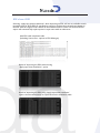
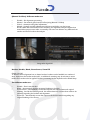
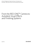
HUD display in Nucoda & Phoenix
Font set to : OCR A Extended
BG set to : Red with 50% Transparency
Exported file, with font and colour options
Implementation:
The burn-in is selected from the drop down menu in the GUI (or Precision)
When exporting material there is an additional selection box that will allow you to select the
burn in to use from a drop down menu.
Presets
There are some standard presets, they should cover most of the requirements, there are also
some really crazy ones that have a lot of information you may not need.
MonitorHUD_001.grids and MonitorHUD_002.grids, are now included with the Nucoda installation in the C:\nucoda\2012.x\root\monitorHUDs folder, any graphic or logos you want
to reference, must also be placed in this folder, included is a DigitalVision.png and the usual
grayscale.png images for testing.
These .grids files are in addition to the MonitorHUDs.grids file that was there before, the presets in all the files are automatically read and added together in the list.
For the logo we support any file we can currently import, and also support the Alpha channel
for transparency, PNG files are well suited to this.
We have added a new identifier to allow text to scale between output formats (within reason,
depending on the amount of data and the font size)
Logos will not autoscale, so a logo in an HD frame might be too large for a PAL frame.
Please see Page 526 of the user Manual for detailed information of the Grids Specification.
The following new identifiers were added to 2012.2
burnInTextScale 1.5
Using this identifier will cause the size and position of the burn-in text to reflect the size and
positions on the HUD (best value is 1.5)
textSizeBase 1080.0
Using this identifier when creating a preset will allow the burn-in to scale accordingly when
switching to other frame sizes, allowing the same preset to be used for multiple frame sizes.
In this case, the preset was set up for a HD frame, so the number after the Identifier was set to
1080
textFont “Arial”
Set the font for the burn-in. Use Windows Word Pad to get the correct name of the font.
textStyle “bold italic”
Set the text style
bgColor 0, 0, 0, 0.5 (RGB and Alpha)
Set the colour for background boxes for text.
dropShadow 0.5 1 -1
Sets up a drop shadow with opacity 0.5, offset 1 pixel to the right, and 1 pixel down (relative
to the main text)
The following new HUD fields were added to 2012.2
##compName - Composition Name
##compDescription - Composition Description field
The composition and composition description fields are handy for adding data such as version information to the burn-in. Please note, that these are refreshed only when reloading the
composition, or if you update the fields in the Library view (double click the field to update.)
##masterLocation - Location of the Src file
This field will add the source path for the files (handy for editors who like changing the names
of their RED files.
Additional new fields available in the HUD (case sensitive)
Scene and Take Info
##SourceId
##Take
##Scene
##Camroll
##Slate
##SoundRoll
##Director
##ProjectName
##DoP
##Cameraman
##DailiesColorist
##DateOfShoot
Arri RAW
##ARRI.Camera
##ARRI.Scale
##ARRI.ISO
##ARRI.ColourTemp
##ARRI.Tint
##ARRI.Sharpness
##ARRI.ColorEncoding
##ARRI.ColorSpace
##ARRI.DebayerMode
Red RAW
##R3D.ASA
##R3D.Brightness
##R3D.Contrast
##R3D.DRX
##R3D.Detail
##R3D.Exposure
##R3D.FLUT
##R3D.HDRBlend
##R3D.Kelvin
##R3D.OLPF
##R3D.Saturation
##R3D.Shadow
##R3D.Tint
##R3D.Denoise
##R3D.OLPF
##R3D.Detail
##R3D.ColorSpace
##R3D.ColorScience
##R3D.HDRBlendMode”
##R3D.GammaCurve
##R3D.DecodeQuality
Phantom Files
##CINE.Bright
##CINE.Gamma
##CINE.Scale
##CINE.Contrast
##CINE.Saturation
##CINE.DecodeQuality
##CINE.WBGain_R
##CINE.WBGain_B
SI2K
##SI2K.decodeResolution
##SI2K.advancedDetail
##SI2K.SATU
##SI2K.LOOK
##SI2K.gammaCurve
##SI2K.PROCESSING_LOOK_FILE
HUD Example for Burn in
The following is the text from TC HUD 1 - The most basic preset - Tape name and Src TC
monitorGrid 1.0 -1
{
name “TC HUD 1” ;
units “normalised” ;
burnInTextScale 1.5 ;
textSizeBase 1080.0 ;
color 1.0 1.0 1.0 1.0 ;
bgcolor 0, 0, 0, 0.2 ;
origin “top” “left” ;
textFont “Arial” ;
anchor “middle” “left” ;
textSize 30.0 ;
color 1.0 1.0 1.0 1.0 ;
text .65 .90 “Source : ##srcTimeTimecode” ;
}
textSize 20.0 ;
text .05 .90 “Tape : ##srcTape” ;
By looking at the presets you will easily be able to add your own presets or modify the defaults, however, you should make a backup of your .grids file, as it will be overwritten if it has
the same name and Nucoda is re-installed.
monitorGrid 1.0 -1
This is the opening line and is a requirement
{
Start of the preset
name “TC HUD 1” ;
Preset Name (must be unique across all .grids files) Strings always end with a ;
With normalised units, the image coordinates are normalised to the range 0.0
units “normalised” ;
to 1.0. This is the most flexible unit to use with burn ins, to make scaling
between frame sizes possible)
So, for example, the position 0.2 0.3 would be 20% from the left hand edge
burnInTextScale 1.5 ;
and 30% from the top if the origin is set to “Top” “Left”
textSizeBase 1080.0 ;
Additional text scaling applied for Burn-In text only, this value matches
your HUD and Burn-In output more closely.
color 1.0 1.0 1.0 1.0 ;
This value sets the basis for scaling Text up or Down to other outputs It should be set equal to the resolution you create the preset in.
This set the font colour 1.0 (100%) R G B and A. Example :
White faded text is 1.0 1.0 1.0 .50 (R 100% G 100% B 100% A50%)
This sets the colour and transparency for the boxes behind the text
bgcolor 0, 0, 0, 0,2
Starting position from where all elements are placed
origin “top” “left” ;
Name of the font to render the text (tip: use Wordpad to check the actual font name in windows)
The anchor for the text boxes - in this case the middle of the box vertically and the left side of the box horizontally
textFont “Arial” ;
anchor “middle” “left” ;
textSize 30.0 ;
Size of the text (point size)
color 1.0 1.0 1.0 1.0 ;
Re-use identifiers to change colours in the preset, please note, all identifiers
used will affect all text afterwards, till you use another identifier to change it back.
text .65 .90 “Source : ##srcTimeTimecode” ;
textSize 30.0 ;
text .05 .90 “Tape : ##srcTape” ;
}
This is a text Element - Placed 65% from the left hand side and 90% from th top of the image - Label is Source: and the data displayed is the Source Timecode
Size of the text (point size)
Preset End
Using a single # will allow for comments - everything after a single # is ignored.
Apart from the “name”,any of the other identifiers can be used multiple times, so you can change the font, colour,
size and alignment to different values in each preset.
EDL import and export options
There have been a significant amount of enhancements made to EDL handling in Nucoda
and Phoenix.
Changes to EDL export:
There are four new options in the EDL export dialog box.
- 8 Chars (CMX Legal) - This will export tapenames up to 8 Chars only, spaces are replaced
with underscores and names are truncated. When a tape name is truncated an FCP style
translate comment is added to the EDL
- 32 Chars - This will export tapenames up to 32 Chars only, spaces are replaced with underscores and names are truncated.
- 255 Chars - This will export tapenames up to 255 Chars only, spaces are replaced with
underscores and names are truncated. When a tape name is truncated an FCP style translate
comment is added to the EDL
- Export Bookmarks - This will export Nucoda bookmarks and add them to the EDL as comments with marker colour and timecode.
Changes to EDL import:
There are three new options in the EDL
import dialog box.
- Apply tape name translations
- Strip clip name extensions
- Import Locators as bookmarks
EDL’s from AVID
Selecting “apply tape name translations” when importing an EDL will use an available translation table from an AVID EDL (If specified on export) to replace the truncated tape names in
the EDL with the original source names in the translation table. Please note that AVID EDL
export will automatically replace spaces in tape name with an underscore.
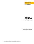
Avid EDL with translation table
(Including Source files - options in EDL Manager)
Result of importing the EDL without using
“Apply tape name translation” option
Result of importing the EDL using “Apply tape name translation”
option, the truncated names are replaced from the translation table.
EDL’s from FCP
The following example from Final Cut Pro has had the Reels replaced by truncated names
when it was exported from FCP.
Using the “apply tape name translation” option when loading this EDL will automatically replace the truncated tape names with the originals based on the clip name field.
Original EDL - Note truncated sources
Translated EDL - Tape name is replaced
with clip name from FCP Reel Comment
This EDL only has AX - Auxiliary sources as reels, when we detect the string in the EDL
* PROBLEM WITH EDIT: - The reel name will set to “Unknown” when using the
“apply tape name translation” option
The reason for using only the first part of the string is that some EDL’s will warn that there is
no reel name, and sometimes that there is no timecode, when in fact both are missing. In this
way we will always replace the source name when a problem is flagged.
Selecting “strip clipname extensions” will remove the last full stop and trailing characters
from the clip names, allowing conform from clipname.
Sources replaced with “Unknown”
AX Sources
clip names stripped of extensions
EDL’s from FCP
EDL’s imported into FCP require 2 spaces after the SOURCE FILE: xxxx
comment, if there was only one space, the source file would be incorrectly interpreted by FCP,
Nucoda now exports EDL’s that conform to this convention.
Support for EDL’s with Locator (marker) information
When exporting an EDL from the Avid, there is an option to include locator information in the
EDL. Nucoda will now read in interpret the information and colour match the locators, placing them on the Nucoda timeline as Timeline Markers.
In the export options, you can also select to export thew markers from Nucoda in a similar
way.
Support for EDL’s with extended CDL information
Due to the specification of CMX not allowing lines longer than 80 char, when creating a CDL
with extended precision values (4 decimal points) the EDL’s created by Avid will automatically
place the values exceeding 80 chars on the next EDL line, preceded by an *
000003 A007R1Y8 V C
10:25:30:21 10:29:16:19 01:04:45:11 01:08:31:09
* FROM CLIP NAME: 003
* ASC_SOP (1.041984 1.041675 1.041162)(-0.040069 -0.033391 -0.041859)(1.065496 1.0
* 66012 1.066495)
* ASC_SAT 1.59
Nucoda will correctly read and interpret these values from the EDL.
DVO Stereo Fix tool
The DVO Stereo Fix tool has been extensively updated and has many new options and parameters available to the user. The tool can only be applied as a an input effect and will be applied
to the Left and Right eyes simultaneously.
View and orientation
Mute: On/Off
Mutes the colour match as well as the align match and associated border/blanking modes.
The parameters in this section regarding view and orientation are active, i.e. SwapEyes/
ViewMode/Mirror/Flip. Can be used to view before and after, while correcting any necessary
mirror/flip.
Swap Eyes: On/Off
Swaps left and right eye on output. All parameters referring to either left and right are associated with the source left and right tracks, and as such, the actual processing is not affected by
swapping eyes on the output.
View Mode: Normal, Blended, Side-By-Side
This control allows different view modes to be applied on the output, mainly for visualization
purposes. The different modes are:
•
Normal – Normal separate left and right outputs.
•
Blended – Blends left and right image, which could be used to verify alignment
processing.
•
Side-By-Side – Displays left and right images side-by-side with halved horizontal reso
lution. If this mode is used to verify colour matching simultaneously, please note that many monitors might have colour reproduction which varies spatially or by viewing angle.
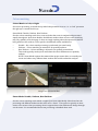
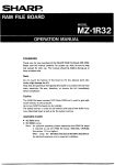
Using the Chequerboard comparison view, the images are clearly not correctly oriented
Auto Mirror/Flip: Disable, Left, Right
Automatically determines mirror and flip between left and right eye. A detected required mirror/flip is applied to the eye which the parameter is set to. The automatic operation will also
follow any manual settings applied to the other eye regarding mirror and flip.
Images are now correctly oriented using Auto Mirror
Mirror Left: On/Off : Manually set left eye to be mirrored.
Mirror Right: On/Off : Manually set right eye to be mirrored.
Flip Left: On/Off : Manually set left eye to be flipped (vertically).
Flip Right: On/Off : Manually set right eye to be flipped (vertically).
Colour matching
Colour Match: to Left, to Right
Sets colour processing to match the eye which the parameter is set to, i.e. “to Left” processes
the right eye to match the left eye.
Scene Mode: Disable, Uniform, Non-Uniform
Sets the colour matching mode for a scene such that the scene is analysed and processed
equally throughout. Apart from disable, the different modes relates to how colour matching
may vary spatially over the image. It does not imply anything about the spectrum transform
being uniform/non-uniform. To be specific, the different modes available are:
•
Disable – No colour match processing is performed (on scene basis).
•
Uniform – Colour matching is assumed to be spatially uniform.
•
Non-Uniform – Colour matching is allowed to be spatially non-uniform.
This mode typically works just as well when the colour differences are spatially
uniform.
NOTE: Scene Mode requires that material has proper scene edits, as normally one scene can behave very different from another and would confuse the analysis.
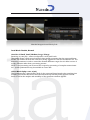
Images are colour matched
Frame Mode: Disable, Uniform, Non-Uniform
Sets the colour matching mode which is applied per frame individually. Other than that, the
processing and different modes are the same as for “Scene”. This option is typically an alternative to the scene colour processing, when it appears that colour differences change throughout the scene. It’s recommended that scene processing is disabled when used.
Matched images viewed Side by Side
Local Mode: Disable, Normal
Area Size: X-Small, Small, Medium, Large, X-Large
Sensitivity: 0-1023 (64) – values correspond to 10-bit pixel levels.
This option allows a much more localized colour match processing than the scene and frame
modes. The smaller the area size is the more locally aggressive it can be considered to be. The
sensitivity parameter is used to control the allowed difference ranges, but it’s effect is more of
a safety measure rather than a processing amount.
NOTE: Local processing can be turned off to speed up processing of complete scenes/material – speed optimizations may be available at a later date.
Colour Match Safety: 0.0-1.0 (0.5)
This parameter sets a general safety level for the scene and frame based colour matching (not
including local mode, which uses area size and sensitivity instead). Safety applies to black
levels as well as the analysis and variability of the spectrum transform applied.
Align matching
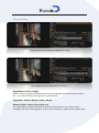
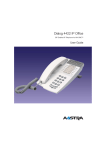
Anaglyph view to show image misalignment easily
Use merge view as an alternative to see errors
Align Match: to Left, to Right
Defines which eye alignment should match to and consequently process the other to match
this, i.e. ‘to Left’ means process right eye to match left eye.
Align Mode: Disable, Manual, Global, Morph
Manual V-Offset: Value for pixel offset (0.0)
The alignment processing is based on scene analysis and frames are processed equally
throughout the scene. The alignment can also be set manually or adjusted with a global offset
(Manual V-Offset). Different modes are:
•
•
•
•
Disable – No alignment processing
Manual – Set manual global vertical offset (using Manual V-Offset)
Global – Automatic and global adjustment
Morph – Spatially variable adjustment with linear variability over the image.
NOTE: Much like scene based colour matching, the alignment analysis requires that material has proper scene edits, as normally one scene can behave very different from another and would confuse the analysis.
Image after alignment
Borders: Disable, Blank, Zoom Source, Zoom Fill
Centre: On/Off
To hide the effect alignment has on frame borders, borders can be handled in a number of
ways. Apart from the border mode itself, an additional centering may be relevant in some
modes and can thus also be applied. Borders processing further depends on the Blank Setup.
The different modes are:
•
•
•
•
Disable – Don’t treat borders.
Blank – Automatically applies necessary blanking to borders.
Zoom Source – Automatically zooms the output to the source frame and original blanking. Just like the blanking mode, this mode takes into account what needs to be excluded regarding the borders and alignment.
Zoom Fill – Automatically zooms the output to fill the full frame disregarding any
original blanking of the source.
Blank Setup: Auto, Source, Output
Blank Top,Left,Right,Bottom: Each specified by number of pixels (0)
Defines if blanking is set up by automatic analysis or manually in relation to source or the output. Blanking affects the border processing and it’s effect will depend on the ‘Borders’ mode
setting. Typical use is ‘Auto’ which determines the blanking by automatic analysis. The mode
‘Source’ allows the user to specify this manually instead. The mode ‘Output’ allows the user to
specify blanking completely manually based on the output alone, i.e. user needs to manually
regard frame effects from the alignment processing as well as the original source frame blanking. Consider ‘Output’ an advanced mode.
Image Systems AB (HQ)
Ågatan 40
SE-582 22 Linköping
Sweden
Tel:+46 (0)13 200 100
Fax:+46 (0)13 200 150
Digital Vision (UK)
11 Wardour Mews
London, W1F 8AN
United Kingdom
Tel:+44(0)20 7734 8282
Fax:+44(0)20 7292 6969
Digital Vision
Telefonvägen 30
126 26 Hägersten
Sweden
Tel:+46 (0)8 546 18200
Fax:+46 (0)8 546 18209
Digital Vision (US)
6464 Sunset Blvd/Suite 830
Hollywood, CA 90028
USA
Tel:+1 818 769 8111
Fax:+1 818 769 1888
www.digitalvision.tv