1
Chapter 7
Interrupt Controller
7.2 Trigger Modes
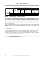
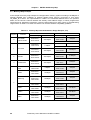
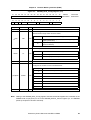
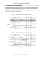
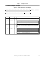
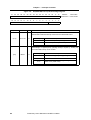
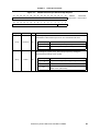
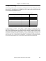
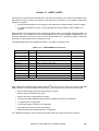
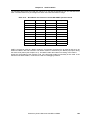
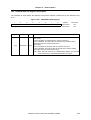
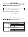
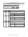
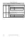
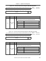
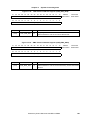
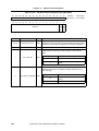
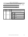
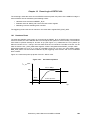
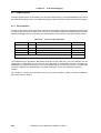
Edge-trigger or level-trigger modes are available for each interrupt input. The trigger type is defined by
means of the assigned bit in the TRIGREG register. For the edge-trigger mode setting, differentiation
can be made between a positive and negative edge evaluation. This is set in the EDGEREG register.
Edge-trigger with positive edge is the default trigger mode assignment for all interrupts. The active level
in level-trigger mode is always “high”.
The interrupt input signal must be present for at least one clock cycle in edge-trigger mode. The input
signal must be present until confirmation of the ARM946E-S CPU in level-trigger mode. Shorter signals
result in loss of the event.
7.3 Masking the Interrupt Inputs
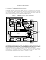
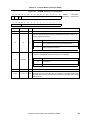
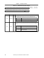
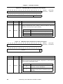
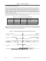
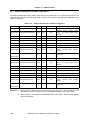
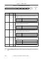
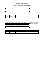
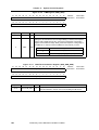
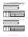
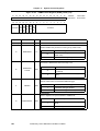
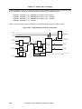
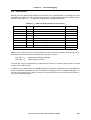
Each IRQ interrupt can be enabled or disabled individually. The MASKREG register is available for this
purpose. The interrupt mask acts only after the IRREG interrupt request register. That is, an interrupt is
entered in the IRREG register in spite of the block in the MASKREG register. After a reset, all mask bits
are set and, thus, all interrupts are disabled. At a higher level, all IRQ interrupts can be disabled globally
via a command. When IRQ interrupts are enabled globally via a command, only those IRQ interrupts
that are enabled by the corresponding mask bit in the MASKREG register are enabled.
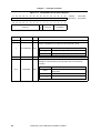
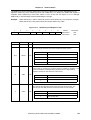
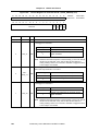
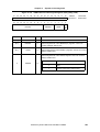
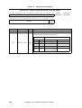
For the FIQ interrupts, only selective masking by the mask bits in the FIQ_MASKREG register is
possible. After a reset, all FIQ interrupts are disabled. A detected FIQ interrupt request is entered in the
FIQ interrupt request register. If the interrupt is enabled in the mask register, processing takes place in
the priority logic. If the interrupt request is accepted by the ARM946E-S CPU and an entry is made in
the in-service request register (ISR), the corresponding bit is reset in the IRREG register. Each bit that
is set in the IRREG register can be deleted via software. For this purpose, the number of the bit to be
reset in the IRCLVEC register is transferred to the interrupt controller.
7.4 Software Interrupts for IRQ
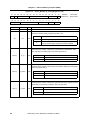
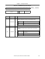
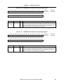
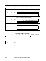
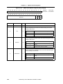
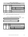
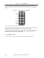
Each IRQ interrupt request can be triggered by setting the bit corresponding to the input channel in the
SWIRREG software interrupt register. Multiple requests can also be entered in the 16-bit SWIRREG
register. The software interrupt requests are received directly in the IRREG register and, thus, treated
like a hardware IRQ. Software interrupts can only be triggered by the ARM946E-S processor because
only this processor has access rights to the interrupt controller.
7.5 Nested Interrupt Structure
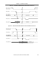
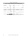
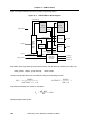
When enabled by the interrupt priority logic, an IRQ interrupt request causes an IRQ signal to be
output. Similarly, an FIQ interrupt request causes the FIQ signal to be output to the CPU.
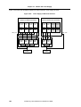
If the request is accepted by the CPU (in the IRQACK or FIQACK register), the bit corresponding to the
physical input is set in the ISREG or FIQISR register. The IRQ/FIQ signal is revoked. The ISR bit of the
accepted interrupt remains set until the CPU returns an “End-of-interrupt” command to the interrupt
controller. As long as the ISR bit is set, interrupts with lower priority in the priority logic of the interrupt
controller are disabled. Interrupts with a higher priority are allowed by the priority logic to pass and
generate an IRQ/FIQ signal to the CPU. As soon as the CPU accepts this interrupt, the corresponding
ISR bit in the ISREG or FIQISR register is also set. The CPU then interrupts the lower-priority interrupt
routine and executes the higher interrupt routine first. Lower-priority interrupts are not lost. They are
entered in the IRREG register and are processed at a later time when all higher-priority interrupt
routines have been executed.
Preliminary User’s Manual A17812EE1V1UM00
75