1
AN3123
Application note
Using the UART interfaces in the SPEAr embedded MPU family
Introduction
The SPEAr embedded MPU family is a family of configurable MPUs, based on the ARM926
CPU core. Each member of the SPEAr MPU family has one or more embedded ARM PL011
UARTs for asynchronous communications. This application note describes how to configure
the UART and transmit and receive data.
A Linux driver is available in the SPEAr Linux support package (LSP), refer to the SPEAR
Linux support package (LSP) user manual (UM0851) for a description of how to use this
driver.
Section 10 of this application note describes an OS independent hardware abstraction layer
(HAL) for the SPEAr UART which you can use as a starting point for developing your own
HAL code.
December 2009
Doc ID 16862 Rev 1
1/28
www.st.com
Contents
AN3123
Contents
1
Purpose and scope . . . . . . . . . . . . . . . . . . . . . . . . . . . . . . . . . . . . . . . . . . 4
2
UART signals . . . . . . . . . . . . . . . . . . . . . . . . . . . . . . . . . . . . . . . . . . . . . . . 5
3
2.1
SPEAr600 . . . . . . . . . . . . . . . . . . . . . . . . . . . . . . . . . . . . . . . . . . . . . . . . . 5
2.2
SPEAr300 . . . . . . . . . . . . . . . . . . . . . . . . . . . . . . . . . . . . . . . . . . . . . . . . . 5
2.3
SPEAr310 . . . . . . . . . . . . . . . . . . . . . . . . . . . . . . . . . . . . . . . . . . . . . . . . . 6
2.4
SPEAr320 . . . . . . . . . . . . . . . . . . . . . . . . . . . . . . . . . . . . . . . . . . . . . . . . . 7
Clock source and frequency . . . . . . . . . . . . . . . . . . . . . . . . . . . . . . . . . . 9
3.1
4
Clock related registers . . . . . . . . . . . . . . . . . . . . . . . . . . . . . . . . . . . . . . . . 9
Changing the UART baud rate on the fly . . . . . . . . . . . . . . . . . . . . . . . 10
4.1
Baud rate related registers . . . . . . . . . . . . . . . . . . . . . . . . . . . . . . . . . . . . 10
5
UART protocol flow control . . . . . . . . . . . . . . . . . . . . . . . . . . . . . . . . . . 11
6
UART controller data flow . . . . . . . . . . . . . . . . . . . . . . . . . . . . . . . . . . . . 12
6.1
7
UART interrupts . . . . . . . . . . . . . . . . . . . . . . . . . . . . . . . . . . . . . . . . . . . . 14
7.1
Interrupt Sources . . . . . . . . . . . . . . . . . . . . . . . . . . . . . . . . . . . . . . . . . . . 14
7.2
Interrupt types . . . . . . . . . . . . . . . . . . . . . . . . . . . . . . . . . . . . . . . . . . . . . 14
7.3
8
2/28
UART data registers . . . . . . . . . . . . . . . . . . . . . . . . . . . . . . . . . . . . . . . . . 12
7.2.1
UARTRXINTR . . . . . . . . . . . . . . . . . . . . . . . . . . . . . . . . . . . . . . . . . . . . 14
7.2.2
UARTTXINTR . . . . . . . . . . . . . . . . . . . . . . . . . . . . . . . . . . . . . . . . . . . . 15
7.2.3
UARTRTINTR . . . . . . . . . . . . . . . . . . . . . . . . . . . . . . . . . . . . . . . . . . . . 15
7.2.4
UARTMSINTR . . . . . . . . . . . . . . . . . . . . . . . . . . . . . . . . . . . . . . . . . . . . 15
7.2.5
UARTEINTR . . . . . . . . . . . . . . . . . . . . . . . . . . . . . . . . . . . . . . . . . . . . . 15
7.2.6
UARTINTR . . . . . . . . . . . . . . . . . . . . . . . . . . . . . . . . . . . . . . . . . . . . . . . 15
Interrupt related registers . . . . . . . . . . . . . . . . . . . . . . . . . . . . . . . . . . . . . 16
DMA interface . . . . . . . . . . . . . . . . . . . . . . . . . . . . . . . . . . . . . . . . . . . . . 17
8.1
DMA operation . . . . . . . . . . . . . . . . . . . . . . . . . . . . . . . . . . . . . . . . . . . . . 17
8.2
DMA registers . . . . . . . . . . . . . . . . . . . . . . . . . . . . . . . . . . . . . . . . . . . . . . 18
Doc ID 16862 Rev 1
AN3123
Contents
9
UART modem operation . . . . . . . . . . . . . . . . . . . . . . . . . . . . . . . . . . . . . 19
10
OS-independent SPEAr UART HAL . . . . . . . . . . . . . . . . . . . . . . . . . . . . 21
10.1
SetBaseDevice() . . . . . . . . . . . . . . . . . . . . . . . . . . . . . . . . . . . . . . . . . . . 21
10.2
GetBaudDivisor() . . . . . . . . . . . . . . . . . . . . . . . . . . . . . . . . . . . . . . . . . . . 21
10.3
UART_Init() . . . . . . . . . . . . . . . . . . . . . . . . . . . . . . . . . . . . . . . . . . . . . . . . 22
10.4
UART_Configure() . . . . . . . . . . . . . . . . . . . . . . . . . . . . . . . . . . . . . . . . . . 22
10.5
UART_Transmit() . . . . . . . . . . . . . . . . . . . . . . . . . . . . . . . . . . . . . . . . . . . 23
10.6
UART_Receive() . . . . . . . . . . . . . . . . . . . . . . . . . . . . . . . . . . . . . . . . . . . 23
10.7
UART_Disable() . . . . . . . . . . . . . . . . . . . . . . . . . . . . . . . . . . . . . . . . . . . . 24
10.8
UART_IsTxFIFOFull() . . . . . . . . . . . . . . . . . . . . . . . . . . . . . . . . . . . . . . . . 24
10.9
UART_IsTxFIFOEmpty() . . . . . . . . . . . . . . . . . . . . . . . . . . . . . . . . . . . . . 24
10.10 UART_IsRxFIFOFull() . . . . . . . . . . . . . . . . . . . . . . . . . . . . . . . . . . . . . . . 24
10.11 UART_IsRxFIFOEmpty() . . . . . . . . . . . . . . . . . . . . . . . . . . . . . . . . . . . . . 24
10.12 UART_IntEnable() . . . . . . . . . . . . . . . . . . . . . . . . . . . . . . . . . . . . . . . . . . 24
10.13 UART_IntDisable() . . . . . . . . . . . . . . . . . . . . . . . . . . . . . . . . . . . . . . . . . . 25
10.14 UART_IntClear() . . . . . . . . . . . . . . . . . . . . . . . . . . . . . . . . . . . . . . . . . . . . 25
10.15 UART_GetIntSrc() . . . . . . . . . . . . . . . . . . . . . . . . . . . . . . . . . . . . . . . . . . 25
Appendix A Acronyms . . . . . . . . . . . . . . . . . . . . . . . . . . . . . . . . . . . . . . . . . . . . . . 26
Revision history . . . . . . . . . . . . . . . . . . . . . . . . . . . . . . . . . . . . . . . . . . . . . . . . . . . . 27
Doc ID 16862 Rev 1
3/28
Purpose and scope
1
AN3123
Purpose and scope
UART is one of the most commonly used serial interface peripherals. It is also known as the
serial communications interface, or SCI. The most common use of the UART is to
communicate to a PC serial port using the RS-232 protocol.
RS-232 is a standard electrical interface for serial communications defined by the Electronic
Industries Association ("EIA").
Serial communications include most network devices, keyboards, mice, modems, and
terminals. When referring to serial devices or ports, they are either labeled as data
communications equipment ("DCE") or data terminal equipment ("DTE").
The UART can transmit and receive data serially. It is often necessary to regulate the flow of
data when transferring data between two serial interfaces. The first method is often called
"software" flow control and uses special characters to start (XON or DC1) or stop (XOFF or
DC3) the flow of data. The second method is called "hardware" flow control and uses the
RS-232 CTS and RTS signals instead of special characters. Because hardware flow control
uses a separate set of signals, it is much faster than software flow control which needs to
send or receive multiple bits of information to do the same thing.
4/28
Doc ID 16862 Rev 1
AN3123
2
UART signals
UART signals
SPEAr600 has 2 UARTs. SPEAr300, SPEAr310 and SPEAr320 have 1, 6 and 3 UARTs
respectively. The following tables list the UART pin connections and register base addresses
for each case.
2.1
SPEAr600
Table 1.
External pin connection on SPEAr600
Signal name
Ball
Direction
UART1_TXD
AA19
Output
UART2_TXD
AA20
Output
UART1_RXD
AB19
Input
UART2_RXD
AB20
Input
Table 2.
2.2
Function
Serial Data Out
Serial Data In
Pin type
TTL output buffer
3.3 V capable, 4 mA
TTL input buffer
3.3 V tolerant, PD
Memory map on SPEAr600
Peripheral
Start address
End address
UART1
0xD000.0000
0xD007.FFFF
UART2
0xD008.0000
0xD00F.FFFF
SPEAr300
Table 3.
External pin connection
Signal
Ball
Direction
RX DATA
D1
Input
TX DATA
E4
Output
RTS
B8
CTS
A8
DTR
D9
DSR
B9
DCD
A9
RI
C9
Table 4.
I/O
Function
Pin type
Shared I/O
TTL output buffer
3.3 V capable,
up to 10 mA
TTL input buffer
3.3 V tolerant, PU/PD
Memory map on SPEAr300
Peripheral
Start address
End address
UART
0xD000.0000
0xD007.FFFF
Doc ID 16862 Rev 1
5/28
UART signals
AN3123
In SPEAr300, the device offers several different PL_GPIO sharing modes. Different
blocks/IPs are available in different configuration modes.
This has an effect on the above mentioned UART signals also. Not all SPEAR300 UART
signals in Table 3 are available in all configurations.
This is because for many applications UART is used in NULL modem mode and only
UART_RX & UART_TX are sufficient.
There are 13 possible UART configurations in SPEAr300 which can be selected by RAS
control register 2.
In configuration 1 & configuration 2, the UART with modem control lines is available.
In configurations 3 to 13, the UART without modem control lines is available (see Table 6).
Table 5.
UART configurations for SPEAr300
Signal
Configuration 1
Configuration 2
Configurations 3 to 13
PL_GPIO[42]
UART_DTR
UART_DTR
-
PL_GPIO[41]
UART_RI
UART_RI
-
PL_GPIO[40]
UART_DSR
UART_DSR
-
PL_GPIO[39]
UART_DCD
UART_DCD
-
PL_GPIO[38]
UART_CTS
UART_CTS
-
PL_GPIO[37]
UART_RTS
UART_RTS
-
PL_GPIO[3]
UART_RX
UART_RX
UART_RX
PL_GPIO[2]
UART_TX
UART_TX
UART_TX
Note:
On PL_GPIO[3] and PL_GPIO[2] UART_RX and UART_TX are multiplexed with external
memory controller (FSMC) signals /E4 and /E3 respectively.
2.3
SPEAr310
In SPEAr310 the external pin connections of UART1 are the same as in SPEAr300.
You can configure the device to have either
●
up to 6 UARTs without modem control lines or
●
1 UART with modem control lines.
Refer to Table 3.
6/28
Doc ID 16862 Rev 1
AN3123
UART signals
Table 6.
UART configurations for SPEAr310
Signal
Ball
Alternate function
RAS normal mode
PL_GPIO[44]
A10
-
UART5_TX
PL_GPIO[43]
E9
-
UART5_RX
PL_GPIO[42]
D9
UART0_DTR
UART5_TX
PL_GPIO[41]
C9
UART0_RI
UART5_RX
PL_GPIO[40]
B9
UART0_DSR
UART4_TX
PL_GPIO[39]
A9
UART0_DCD
UART4_RX
PL_GPIO[38]
A8
UART0_CTS
UART3_TX
TTL output buffer
3.3 V capable,
up to 10 mA
TTL input buffer
PL_GPIO[37]
B8
UART0_RTS
UART3_RX
3.3 V tolerant, PU/PD
PL_GPIO[3]
D1
UART0_RX
UART0_RX
PL_GPIO[2]
E4
UART0_TX
UART0_TX
PL_GPIO[1]
E3
UART1_TX
PL_GPIO[0]
F3
UART1_RX
Table 7.
2.4
Pin type
Memory map on SPEAr310
Peripheral
Start address
End address
UART1
0xD000.0000
0xD007.FFFF
UART2
0xB200.0000
0xB207.FFFF
UART3
0xB208.0000
0xB20F.FFFF
UART4
0xB210.0000
0xB217.FFFF
UART5
0xB218.0000
0xB21F.FFFF
UART6
0xB220.0000
0xB227.FFFF
SPEAr320
In SPEAr320 the external pin connections of UART1 are the same as the UART in
SPEAr300. Refer to Table 3.
You can configure the device to have:
●
Table 8.
up to 3 UARTs, 1 without modem control lines and 2 with modem control lines.
UART configurations for SPEAr320
Signal
Ball
Alternate
function
Config. 1
Config. 2
Config. 3
PL_GPIO[44]
B10
PL_GPIO[44]
A10
-
UART1_DSR
PL_GPIO[43]
E9
-
UART1_RTS
Config. 4
UART1_DCD
Doc ID 16862 Rev 1
7/28
UART signals
Table 8.
AN3123
UART configurations for SPEAr320 (continued)
Signal
Ball
Alternate
function
PL_GPIO[42]
D9
UART0_DTR
PL_GPIO[41]
C9
UART0_RI
PL_GPIO[40]
B9
UART0_DSR
PL_GPIO[39]
A9
UART0_DCD
PL_GPIO[38]
A8
UART0_CTS
PL_GPIO[37]
B8
UART0_RTS
PL_GPIO[36]
Config. 3
Config. 4
C8
UART1_CTS
UART1_CTS
PL_GPIO[35]
D8
UART1_DTR
UART1_DTR
PL_GPIO[34]
E8
UART1_RI
UART1_RI
PL_GPIO[33]
E7
UART1_DCD
PL_GPIO[32]
D7
UART1_DSR
PL_GPIO[31]
C7
UART1_RTS
PL_GPIO[29]
A7
UART1_TX
UART1_TX
UART1_TX
UART1_TX
UART1_TX
PL_GPIO[28]
A6
UART1_RX
UART1_RX
UART1_RX
UART1_RX
UART1_RX
PL_GPIO[3]
D1
UART0_RX
PL_GPIO[2]
E4
UART0_TX
PL_GPIO[1]
E3
UART2_TX
UART2_TX
UART2_TX
UART2_TX
PL_GPIO[0]
F3
UART2_RX
UART2_RX
UART2_RX
UART2_RX
Table 9.
8/28
Config. 1
Config. 2
Memory map on SPEAr300
Peripheral
Start address
End address
UART1
0xD000.0000
0xD007.FFFF
UART2
0xA300.0000
0xA3FF.FFFF
UART3
0xA400.0000
0xA4FF.FFFF
Doc ID 16862 Rev 1
AN3123
3
Clock source and frequency
Clock source and frequency
The reference clock provided to the UART has a frequency ranging from 1.42 MHz to 542.72
MHz.
An auxiliary clock source can also be selected using the Auxiliary clock synthesizer
registers. These are a group of read / write registers in the Miscellaneous register block
which can be used to enable an auxiliary source clock for some of the SPEAR's internal
peripherals, including the UART. The clock synthesizer is a digital signal generator. It is used
to act as a fractional clock divider.
3.1
Clock related registers
●
PERIPHERAL CLOCK CONFIGURE REGISTER is a R/W register used to select the
peripheral clock source. The uart_clksel bit in this register allows you selected the
UART clock source as follows:
–
‘0’
48 MHz (default clock)
–
‘1’
UART Clock Synthesizer
Offset Value: 0x028.
●
PERIP1_CLK_ENB REGISTER is a R/W register using to enable/disable the
peripheral.
–
In SPEAr300, there is a single uart_clkenb bit which enables and disables the
UART-1 clock.
–
In SPEAr600, there are 2 clock enable bits, uart1_clkenb and uart2_clkenb which
enable and disable the UART-1 and UART-2 clock, respectively.
Offset Value: 0x02C.
Doc ID 16862 Rev 1
9/28
Changing the UART baud rate on the fly
4
AN3123
Changing the UART baud rate on the fly
The baud rate and line control registers (UARTIBRD, UARTFBRD and UARTLCR_H) form a
single 30-bit wide register named UARTLCR, which is updated on a single write strobe
generated by a UARTLCR_H write. So, in order to change the baud rate of the UART on the
fly, you need to perform the following two steps:
4.1
1.
Modify the contents of the UARTIBRD and UARTFBRD registers as per the required
baud rate.
2.
Perform a dummy write to the UARTLCR_H register.
Baud rate related registers
●
UART INTEGER BAUD RATE REGISTER (UARTIBRD) is a 16-bit RW register which
indicates the integer part of the baud rate divisor value.
Offset Value: ‘h024
●
UART FRACTIONAL BAUD RATE REGISTER (UARTFBRD) is a 6-bit RW register
which indicates the fractional part of the baud rate divisor value.
Offset Value: ‘h028
●
UART LINE CONTROL REGISTER (UARTLCR_H) is a 16-bit RW register which
accesses bits 29 to 22 of the UART bit rate and line control register UARTLCR.
Offset Value: ‘h02C
10/28
Doc ID 16862 Rev 1
AN3123
5
UART protocol flow control
UART protocol flow control
Flow control refers to the control of data flow between modems, or between the modem and
a computer. It handles the data in the FIFO buffer and starts and stops data flow between
the modems. Often, one modem may be sending data much faster than the other is able to
receive. Flow control allows the slower device to tell the faster device to pause and resume
data transmission.
There are two ways to handle flow control: hardware (RTS/CTS or DTR/DSR) and software
(Xon/Xoff or DC1/DC3):
●
Hardware flow control is performed using the RTS and CTS signals. These signals may
be software controlled.
●
Software flow control means sending an XOFF character to stop transmission, and
another character to start transmission.
The flow of data bytes in the cable between 2 serial ports is bi-directional so there are 2
different flows (and wires) to consider:
●
Byte flow from the computer to the modem
●
Byte flow from the modem to the computer.
HARDWARE FLOW CONTROL uses two dedicated "modem control" wires to send the
"stop" and "start" signals. Hardware flow control at the serial port works like this:
The two pins, RTS (Request to send) and CTS (Clear to send) are used. When the
computer is ready to receive data it asserts RTS by putting a positive voltage on the RTS pin
(meaning "Request To Send to me"). When the computer is not able to receive any more
bytes, it negates RTS by asserting negative voltage on the pin saying: "stop sending to me".
The RTS pin is connected by the serial cable to another pin on the modem, printer, terminal,
etc. This other pin's only function is to receive this signal. For a printer, another PC, or a
non-modem device, this “other” pin is usually a CTS pin so a "crossover" or "null modem"
cable is required. This cable connects the CTS pin at one end with the RTS pin at the other
end (two wires since each end of the cable has a CTS pin).
For the opposite direction of flow a similar scheme is used. For a non-modem, the RTS pin
sends the signal. Some non-modems may use other pins for flow control such as the DTR
pin instead of RTS.
SOFTWARE FLOW CONTROL uses the main receive and transmit data wires to send the
start and stop signals. It inserts the ASCII control characters DC1 (start) and DC3 (stop) into
the stream of data. Software flow control is slower than hardware flow control and it does not
allow the sending of binary data unless special precautions are taken. For example, you
need to be able to distinguish between an occurrence of a control code like DC3 when it
means a flow control stop and a DC3 that is part of the binary data payload.
Doc ID 16862 Rev 1
11/28
UART controller data flow
6
AN3123
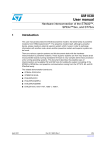
UART controller data flow
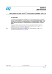
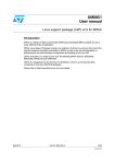
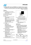
Figure 1.
UART controller data flow
User applications
Receive ()
Transmit ()
User exposed layer
UART hardware abstraction layer (HAL)
UART hardware (ARM Primecell PL011)
Figure 1 illustrates how data flows from user space down to the hardware interfaces and
flows back up.
The reading and writing processes use the HAL functions which are exposed to the user.
Then the corresponding APIs of the UART hardware layer are called for the transmission
and reception of data. The direction of transmission and reception are as shown in Figure 1.
6.1
UART data registers
SPEAr300
Base Address for UART: 0xD0000000
SPEAr600
Base Address for UART1: 0xD0000000
Base Address for UART2: 0xD0080000
Offset Value: ‘h000
12/28
Doc ID 16862 Rev 1
AN3123
UART controller data flow
This is a 16-bit read/write register which contains data:
●
In transmit mode, if FIFOs are enabled, data written to this location is pushed into the
transmit FIFO. If FIFOs are not enabled, data is stored in the transmitter holding
register.
●
In receive mode, if FIFOs are enabled, the data byte and the 4-bit status (break, frame,
parity and overrun) is pushed into the 12-bit receive FIFO. If FIFOs are not enabled,
data byte and status are stored in the receiving holding register.
Doc ID 16862 Rev 1
13/28
UART interrupts
7
AN3123
UART interrupts
UART generates individual maskable active HIGH interrupts. A combined interrupt output is
generated as an OR function of the individual interrupt requests and mapped on IRQ19 of
the vectored interrupt controller VIC in the case of SPEAr300, and on IRQ24 and IRQ25 in
the case of SPEAr600.
7.1
Interrupt Sources
Table 10.
Interrupt sources
Name
Source
UARTRXINTR
Receive FIFO
UARTTXINTR
Transmit FIFO
UARTRTINTR
Receive timeout in Receive FIFO
UARTRIINTR
nUARTRI modem status line change
Combined
Outputs
UARTCTSINTR
nUARTCTS modem status line change
UARTEINTR
UARTDCDINTR
nUARTDCS modem status line change
UARTDSRINTR
nUARTDSR modem status line change
(to Vectored
interrupt controller
VIC IRQ)
UARTOEINTR
Overrun Error
UARTBEINTR
Break Error (in reception)
UARTPEINTR
Parity Error in the Received Character
UARTFEINTR
Framing Error in Received Character
7.2
Interrupt types
7.2.1
UARTRXINTR
This interrupt is asserted when one of the following events occurs:
14/28
●
If the FIFOs are enabled (FEN bit set to ‘b1 in UARTLCR_H register) and the Receive
FIFO reaches the programmed trigger level (RXIFLSEL in UARTIFLS register). The
interrupt is then cleared by reading data from the Receive FIFO until it becomes less
than the trigger level, or by clearing the interrupt (writing a ‘b1 to the corresponding bit
of the UARTICR register).
●
If the FIFOs are disabled and data is received thereby filling the location. The interrupt
is then cleared by performing a single read of the Receive FIFO, or by clearing the
interrupt (writing a ‘b1 to the corresponding bit of the UARTICR register).
Doc ID 16862 Rev 1
AN3123
7.2.2
UART interrupts
UARTTXINTR
This interrupt is asserted when one of the following events occurs:
7.2.3
●
If the FIFOs are enabled (FEN bit set to ‘b1 in UARTLCR_H register) and the Transmit
FIFO reaches the programmed trigger level (TXIFLSEL in UARTIFLS register). The
interrupt is then cleared by writing data to the Transmit FIFO until it becomes greater
than the trigger level, or by clearing the interrupt (writing a ‘b1 to the corresponding bit
of the UARTICR register).
●
If the FIFOs are disabled and there is no data in the transmitter single location. The
interrupt is then cleared by performing a single write to the Transmit FIFO, or by
clearing the interrupt (writing a ‘b1 to the corresponding bit of the UARTICR register).
UARTRTINTR
This interrupt is asserted when the Receive FIFO is not empty, and no further data is
received over a 32-bit period. The interrupt is then cleared either when the Receive FIFO
becomes empty through reading all the data (or by reading the holding register), or by
clearing the interrupt (writing a ‘b1 to the corresponding bit of the UARTICR register).
7.2.4
UARTMSINTR
It represents the modem status interrupt that is a combined interrupt of the four individual
modem status lines (nUARTRI, nUARTCTS, nUARTDCS and nUARTDSR). This interrupt is
then asserted if any of the modem status lines change.
7.2.5
UARTEINTR
This error interrupt is triggered when there is an error in the reception of the data. The
interrupt can be caused by a number of different error conditions, such as overrun, break,
parity and framing.
7.2.6
UARTINTR
It is the OR logical function of all the individual masked interrupt sources. That is, this
interrupt is asserted if any of the individual interrupts are asserted and enabled.
Doc ID 16862 Rev 1
15/28
UART interrupts
7.3
AN3123
Interrupt related registers
These are the registers which are used for handling interrupts:
●
INTERRUPT FIFO LEVEL SELECT REGISTER is a 16-bit read-write register. This
register defines the FIFO level at which the UARTTXINTR and UARTRXINTR interrupts
are triggered.
Offset Value: ‘h034
●
INTERRUPT MASK SET/CLEAR REGISTER allows masking and clearing of each
UART interrupt source. Reading from this 16 bit read/write register gives the current
value of the mask on relevant interrupt.
Offset Value: ‘h038
●
RAW INTERRUPT STATUS REGISTER is a read-only register. This register gives the
current raw status value of the corresponding interrupt.
Offset Value: ‘h03C
●
INTERRUPT CLEAR REGISTER is 16 bit write only register. Writing logic 1 to the
relevant bit clears the corresponding interrupt.
Offset Value: ‘h044
●
MASKED INTERRUPT STATUS REGISTER is a 16 bit read-only register which gives
current masked status value of the corresponding interrupt.
Offset Value: ‘h040
16/28
Doc ID 16862 Rev 1
AN3123
8
DMA interface
DMA interface
DMA allows devices to transfer data without subjecting the processor to a heavy overhead.
Otherwise, the processor would have to copy each piece of data from the source to the
destination, making it unavailable for other tasks.
SPEAr300 and SPEAr600 provide an ARM PrimeCell® DMA controller (DMAC) able to
service up to 8 independent DMA channels for serial data transfers between single source
and destination (for example, memory-to-memory, memory-to-peripheral, peripheral-tomemory, and peripheral-to-peripheral).
The UART provides a DMA Interface for connecting to a DMA controller. The DMA operation
of the UART is controlled through the UART DMA control register. When the UART is in
FIFO disabled mode (where both FIFOs act like a one-byte holding register), only DMA
single transfer mode can operate, since only one character can be transferred to or from the
FIFO at any time.
●
For transmit:
DMA transfers data from a source address to the transmit FIFO. When the transmit
FIFO is full, then DMA goes into wait state. Then, the UART transmits the data from the
transmit FIFO to the destination address. When there is at least one empty location in
the transmit FIFO then DMA comes out of wait state and again starts transferring data
to the transmit FIFO. In transmit mode, one character consists of up to 8 bits.
●
For receive:
DMA transfers data from the receive FIFO to the address where the data received is to
be stored. The reception process with DMA occurs when the receive FIFO contains at
least one character. When the receive FIFO is empty, then DMA goes into wait state
until there is at least one character in the receive FIFO for the reception process to
occur. In receive mode, one character consists of up to 12 bits.
The burst transfer and single transfer request signals are not mutually exclusive, so
they can both be asserted at the same time. For example, when there is more data than
the watermark level in the receive FIFO, the burst transfer request and the single
transfer request are asserted. When the amount of data left in the receive FIFO is less
than the watermark level, only the single request is asserted. This is useful for
situations where the number of characters left to be received in the stream is less than
a burst.
8.1
DMA operation
First of all, the DMA clock is enabled. In transmission, the TX interrupt is enabled. Then,
DMA is enabled by the DMACConfiguration register. Setting the relevant bit in the
DMACIntTCClear register or in the DMACIntErrClr register, respectively, clears the interrupt
request. The DMA channel to be used is selected, corresponding to which the registers of
that channel are configured. For example, channel 0 is selected, then the DMACC0SrcAddr
register contains the source address of the data which is to be transmitted.
DMACC0DestAddr register contains the address of TX FIFO.
In reception, the RX interrupt is enabled. Then DMA is enabled and all the pending
interrupts on DMA are cleared. For channel 0, the DMACC0SrcAddr contains the address of
RX FIFO and DMACC0DestAddr contains the address where the data is to be received.
Doc ID 16862 Rev 1
17/28
DMA interface
8.2
AN3123
DMA registers
●
UART DMA control register is a 16-bit read/write register. The bits of this register
enable and disable the DMA for the transmit and receive FIFOs. It also changes the
DMA request outputs when an UART error interrupt is asserted.
Offset Value: ‘h048
●
DMACConfiguration register is a RW register which is used to configure the
operation of the DMAC. It enables the DMAC.
Offset Value: 0x030
●
DMACIntTCClear (interrupt terminal count clear) register is a WO register which is
used to clear a terminal count interrupt request.
Offset Value: 0x008
●
DMACIntErrClr (interrupt error clear) REGISTER is a WO register which is used to
clear an error interrupt request.
Offset Value: 0x010
●
DMACCnSrcAddr (channel n source address) register is a RW register which
contains the current source address of the data to be transferred over the n-th DMA
channel.
Offset Value: 0x100 + (n · 0x020)
●
DMACCnDestAddr (channel n destination address) register is a RW register which
contains the current destination address of the data to be transferred over the n-th DMA
channel.
Offset Value: 0x104 + (n · 0x020)
●
DMACCnLLI (channel n linked list item) register is a RW register which contains the
address of the next Linked List Item (LLI). If next LLI is 0, then the current LLI is last in
the chain, and the DMA channel is disabled after all DMA transfers associated with it
are completed.
Offset Value: 0x108 + (n · 0x020)
●
DMACCnControl REGISTER is a RW register which contains control information
about the DMA channel n, such as transfer size, burst size and transfer width.
Offset Value: 0x10C + (n · 0x020)
●
DMACCnConfiguration REGISTER is a RW register which is used to configure the
relevant DMA channel.
Offset Value: 0x110 + (n · 0x020)
18/28
Doc ID 16862 Rev 1
AN3123
9
UART modem operation
UART modem operation
The UART can support both data terminal equipment (DTE) and data communication
equipment (DCE) modes of operation. Table 11 gives a description of the signals in each
mode.
Table 11.
Modem input/output signals in DTE and DCE modes
Signal
Description
DTE
DCE
nUARTCTS
Clear to Send
Request to Send
nUARTDSR
Data Set Ready
Data Terminal Ready
nUARTDCD
Data Carrier Detect
-
nUARTRI
Ring Indicator
-
nUARTRTS
Request to Send
Clear to Send
nUARTDTR
Data Terminal ready
Data Set Ready
nUARTOUT1
-
Data Carrier Detect
nUARTOUT2
-
Ring Indicator
Two dedicated "modem control" wires are used in hardware flow control to send the "stop"
and "start" signals. When the computer is ready to receive data it asserts RTS by putting a
positive voltage on the RTS pin. When the computer is not able to receive any more bytes, it
negates RTS by asserting a negative voltage on the pin. The RTS pin is connected by the
serial cable to another pin on the modem. This other pin's only function is to receive this
signal.
This "other" pin will be the modem's RTS pin. For a modem, a straight-thru cable is used.
For the opposite direction of flow a similar scheme is used. The CTS pin is used to send the
flow control signal to the CTS pin on the PC.
Thus modems and non-modems have the roles of their RTS and CTS pins interchanged.
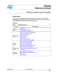
RS-232 hardware handshaking has been specified in terms of communication between
Data Terminal Equipment (DTE) and Data Communications Equipment (DCE).
Most RS-232 connections use 9-pin DSUB connectors. A DTE uses a male connector and a
DCE uses a female connector.
Doc ID 16862 Rev 1
19/28
UART modem operation
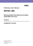
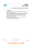
Figure 2.
AN3123
DTE to DCE connection
1
DSR input
RXD input
RTS output
TXD output
CTS input
DTR output
6
1
2
7
2
7
3
8
3
8
4
9
GND
4
9
5
3
8
4
9
6
2
7
3
8
4
9
GND
5
5
Data Communication Equipment
DSUB9 female connector
DTE to DTE connection
6
2
7
2
7
3
8
3
8
4
4
9
5
GND
1
6
9
20/28
2
7
DSUB9 female to DSUB9 male connector
1
GND
DSR output
RXD output
RTS input
TXD input
CTS output
DTR input
DTE to DCE RS-232 cable
DSUB9 male connector
DSR input
RXD input
RTS output
TXD output
CTS input
DTR output
1
6
GND
5
Data Terminal Equipment
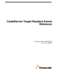
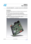
Figure 3.
1
DSR
RXD
RTS
TXD
CTS
DTR
6
5
DSR
RXD
RTS
TXD
CTS
DTR
GND
DTR
CTS
TXD
RTS
RXD
DSR
5
GND
9
5
9
4
8
3
7
2
6
1
DTR output
CTS input
TXD output
RTS output
RXD input
DSR input
4
8
3
7
2
6
1
Data Terminal Equipment
DTE to DTE RS-232 null modem cable
Data Terminal Equipment
DSUB9 male connector
DSUB9 female to DSUB9 female connector
DSUB9 male connector
Doc ID 16862 Rev 1
AN3123
10
OS-independent SPEAr UART HAL
OS-independent SPEAr UART HAL
This section describes an OS independent hardware abstraction layer (HAL) for the SPEAr
UART which you can use as a starting point for developing your own HAL code.
10.1
SetBaseDevice()
This API sets the base address of the UART.
static t_UARTError SetBaseDevice(volatile u32 *SPEAR_UART_APB_BASE,
struct spear_uart_config *dev)
●
UARTId: Identify the UART device
If the UARTId is UART0 or UART1, then it is a valid input for it otherwise it is said to be an
invalid UART ID.
10.2
GetBaudDivisor()
This function returns the integer and fractional values of the baud rate divisor.
static u32 GetBaudDivisor(t_UARTBaudRate BaudRate, u32
*IntegralVal)
●
BaudRate: Baud rate to be configured
●
IntegralVal - Baud rate divisor's integral value
Baud rate is a constant value & can be selected from the table given below
:
Table 12.
Baud rate values
Option
Value
BAUD110
110
BAUD300
300
BAUD1200
1200
BAUD2400
2400
BAUD4800
4800
BAUD9600
9600
BAUD19200
19200
BAUD38400
38400
BAUD57600
57600
BAUD115200
115200
BAUD230400
230400
BAUD460800
460800
Doc ID 16862 Rev 1
21/28
OS-independent SPEAr UART HAL
10.3
AN3123
UART_Init()
This routine is used to initialize the UART. This function sets the default settings and enables
the UART.
t_UARTError UART_Init(struct spear_uart **uart_device, t_UARTId
UARTId)
This function sets the default settings as shown in the example below:
struct spear_uart_config *dev;
dev->FIFOStatus
= FIFO_ENABLE;
dev->BaudRate
= BAUD115200;
dev->WordLength
= DATA8;
dev->StopBitSelect
= STOP1;
dev->ParitySelect
= PARITY_DISABLE;
dev->TxWatermarkLevel
= OneByTwo;
dev->RxWatermarkLevel
= OneByTwo;
dev->TxEnable
= TRUE;
dev->RxEnable
= TRUE;
dev->UARTId
10.4
= UARTId;
UART_Configure()
This function is used to configure a UART device. It first disables the UART, then finds the
integral and fractional baud rate and configures the line control register, control register and
various interrupt registers, etc. and finally enables the UART.
t_UARTError UART_Configure(struct spear_uart_config *dev)
●
UARTId: Identify the UART device
●
Config: Configuration information
The configuration information is selected as follows:
●
ParitySelect: If it is already zero, this means that odd parity is selected. If EVEN then
even parity is selected, otherwise invalid parity is selected.
●
WordLength: Its value can be chosen from the table given below:
Table 13.
WordLength values
Option
22/28
Value
DATA8
WORD_LENGTH_8
DATA7
WORD_LENGTH_7
DATA6
WORD_LENGTH_6
DATA5
Already zero
Doc ID 16862 Rev 1
AN3123
OS-independent SPEAr UART HAL
Apart from the above table, if any other option is given then it is an invalid word length
option.
●
StopBitSelect: If it is already zero then OneStopBit. If it is equal to STOP2 then two stop
bits otherwise invalid stop bit select.
●
FIFOStatus: Its valid inputs are FIFO_Enable or FIFO_Disable (already zero),
otherwise it is a case of invalid FIFO status.
●
TxWatermarkLevel: The interrupt FIFO level is already set to 1/8
Table 14.
●
Option
Value
OneByEight
-
OneByFour
TX_FIFO_TRIG_1BY4
OneByTwo
TX_FIFO_TRIG_1BY2
ThreeByFour
TX_FIFO_TRIG_3BY4
SevenByEight
TX_FIFO_TRIG_7BY8
RxWatermarkLevel: The Interrupt FIFO Level is already set to 1/8
Table 15.
10.5
TxWatermarkLevel values
RxWatermarkLevel values
Option
Value
OneByEight
-
OneByFour
RX_FIFO_TRIG_1BY4
OneByTwo
RX_FIFO_TRIG_1BY2
ThreeByFour
RX_FIFO_TRIG_3BY4
SevenByEight
RX_FIFO_TRIG_7BY8
UART_Transmit()
This API allows to start transmit a given number of characters. It writes character by
character.
t_UARTError UART_Transmit(struct spear_uart_config *dev, u32
NumOfCharToTx, char *Buffer)
10.6
●
NumOfCharToTx: This is the number of characters to be transmitted
●
Buffer: This is the pointer to the characters to be transmitted
UART_Receive()
This routine is used to start receiving a given number of characters. It reads character by
character.
Doc ID 16862 Rev 1
23/28
OS-independent SPEAr UART HAL
AN3123
t_UARTError UART_Receive(struct spear_uart_config *dev, u32
NumOfCharToRx, char *Buffer, u32 *NumOfCharRx, t_UARTRxError
*RxError)
10.7
●
NumOfCharToRx: This is the number of characters to be received
●
Buffer: This is the pointer to the buffer where the data is stored
●
NumOfCharRx: This is the number of characters received before error is encountered
●
RxError: This is the status of error occurred during the reception- framing, parity, break,
overrun or no error.
UART_Disable()
This function is used to disable the UART. It stops the transmission or reception process
after transferring the current byte.
t_UARTError UART_Disable(struct spear_uart_config *dev)
●
10.8
UARTId: identify the UART device
UART_IsTxFIFOFull()
This API is used to check whether the Tx FIFO is full.
t_bool UART_IsTxFIFOFull(struct spear_uart_config *dev)
10.9
UART_IsTxFIFOEmpty()
This function is used to check whether the Tx FIFO is empty.
t_bool UART_IsTxFIFOEmpty(struct spear_uart_config *dev)
10.10
UART_IsRxFIFOFull()
This function is used to check whether the Rx FIFO is full.
t_bool UART_IsRxFIFOFull(struct spear_uart_config *dev)
10.11
UART_IsRxFIFOEmpty()
This function is used to check whether the Rx FIFO is empty.
t_bool UART_IsRxFIFOEmpty(struct spear_uart_config *dev)
10.12
UART_IntEnable()
This API is used to enable the interrupt on the specified UART device.
t_UARTError UART_IntEnable(struct spear_uart_config *dev,
t_UARTIntType IntType)
●
24/28
IntType: identify the interrupt type
Doc ID 16862 Rev 1
AN3123
OS-independent SPEAr UART HAL
All the interrupts required to be enabled should be ORed first and then passed into this
argument.
10.13
UART_IntDisable()
This routine disables the interrupt on the specified UART.
t_UARTError UART_IntDisable(struct spear_uart_config *dev,
t_UARTIntType IntType)
●
IntType: identify the interrupt type
All the interrupts required to be disabled should be ORed first and then passed into this
argument.
10.14
UART_IntClear()
This function clears the interrupt of the specified UART.
t_UARTError UART_IntClear(struct spear_uart_config *dev,
t_UARTIntType IntType)
●
IntType: identify the interrupt type
All the interrupts required to be cleared should be ORed first and then passed into this
argument.
10.15
UART_GetIntSrc()
This routine is used to get the source of the interrupt.
u32 UART_GetIntSrc(struct spear_uart_config *dev)
●
UARTId: identify the UART device
Doc ID 16862 Rev 1
25/28
Acronyms
AN3123
Appendix A
Table 16.
26/28
Acronyms
List of acronyms
Acronym
Definition
ARM
Advanced RISC machine
SPEAr
Structured processor enhanced architecture
SoC
System-on-chip
AMBA
ARM microcontroller bus architecture
APB
Advanced peripheral bus
RI
Ring indicator
DCD
Data carrier detect
DSR
Data set ready
CTS
Clear to send
RTS
Request to send
DTR
Data transmit ready
LBE
Loop back enable
RXIM
Receive interrupt mask
TXIM
Transmit interrupt mask
FEN
FIFO enable
BRK
Send break
DMA
Direct memory access
Doc ID 16862 Rev 1
AN3123
Revision history
Revision history
Table 17.
Document revision history
Date
Revision
15-Dec- 2009
1
Changes
Initial release
Doc ID 16862 Rev 1
27/28
AN3123
Please Read Carefully:
Information in this document is provided solely in connection with ST products. STMicroelectronics NV and its subsidiaries (“ST”) reserve the
right to make changes, corrections, modifications or improvements, to this document, and the products and services described herein at any
time, without notice.
All ST products are sold pursuant to ST’s terms and conditions of sale.
Purchasers are solely responsible for the choice, selection and use of the ST products and services described herein, and ST assumes no
liability whatsoever relating to the choice, selection or use of the ST products and services described herein.
No license, express or implied, by estoppel or otherwise, to any intellectual property rights is granted under this document. If any part of this
document refers to any third party products or services it shall not be deemed a license grant by ST for the use of such third party products
or services, or any intellectual property contained therein or considered as a warranty covering the use in any manner whatsoever of such
third party products or services or any intellectual property contained therein.
UNLESS OTHERWISE SET FORTH IN ST’S TERMS AND CONDITIONS OF SALE ST DISCLAIMS ANY EXPRESS OR IMPLIED
WARRANTY WITH RESPECT TO THE USE AND/OR SALE OF ST PRODUCTS INCLUDING WITHOUT LIMITATION IMPLIED
WARRANTIES OF MERCHANTABILITY, FITNESS FOR A PARTICULAR PURPOSE (AND THEIR EQUIVALENTS UNDER THE LAWS
OF ANY JURISDICTION), OR INFRINGEMENT OF ANY PATENT, COPYRIGHT OR OTHER INTELLECTUAL PROPERTY RIGHT.
UNLESS EXPRESSLY APPROVED IN WRITING BY AN AUTHORIZED ST REPRESENTATIVE, ST PRODUCTS ARE NOT
RECOMMENDED, AUTHORIZED OR WARRANTED FOR USE IN MILITARY, AIR CRAFT, SPACE, LIFE SAVING, OR LIFE SUSTAINING
APPLICATIONS, NOR IN PRODUCTS OR SYSTEMS WHERE FAILURE OR MALFUNCTION MAY RESULT IN PERSONAL INJURY,
DEATH, OR SEVERE PROPERTY OR ENVIRONMENTAL DAMAGE. ST PRODUCTS WHICH ARE NOT SPECIFIED AS "AUTOMOTIVE
GRADE" MAY ONLY BE USED IN AUTOMOTIVE APPLICATIONS AT USER’S OWN RISK.
Resale of ST products with provisions different from the statements and/or technical features set forth in this document shall immediately void
any warranty granted by ST for the ST product or service described herein and shall not create or extend in any manner whatsoever, any
liability of ST.
ST and the ST logo are trademarks or registered trademarks of ST in various countries.
Information in this document supersedes and replaces all information previously supplied.
The ST logo is a registered trademark of STMicroelectronics. All other names are the property of their respective owners.
© 2009 STMicroelectronics - All rights reserved
STMicroelectronics group of companies
Australia - Belgium - Brazil - Canada - China - Czech Republic - Finland - France - Germany - Hong Kong - India - Israel - Italy - Japan Malaysia - Malta - Morocco - Philippines - Singapore - Spain - Sweden - Switzerland - United Kingdom - United States of America
www.st.com
28/28
Doc ID 16862 Rev 1