1
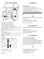
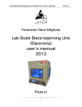
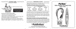
 Troubleshooting
1. When switched the voltage and
current indicators do not light up
1) Check if there is power in the network
2) Check the connection of AC cord in the outlet
2. When adjusting voltage and
current the indicator does not
change the value (constant “0”).
Check the connection of the cord to the load
3. When set, the current
does not stay in current
stabilization mode (red arrow
switches off and green arrow
lights up).
The load does not correspond to
the given value of voltage and current
DIGITAL RECTIFIER
Models: 270.60
60A / 15V
Impulse Power Supply -Precision current & voltage regulator
Self-restore internal short circuit protection
Works under maximum loads for extended periods-Dual voltage 110 V/ 230 V 50–60 Hz
WARNING:
User’s manual
For your safety, follow the Precautions:
1. Do not expose the Power Supply to rain or moisture
2. Do not remove the cover
3. Do not place Power Supply in direct sunlight or near heating source
4. When unplugging the unit from the AC outlet, hold the plastic part.
Do not jerk the power cord and hold the metal part
5. Do not block the ventilation holes. Place the Power Supply at least 10 cm ( 4 inches )
away from the walls or other obstacles, that may restrict air circulation
6. Do not stand on or place heavy objects on the Power Supply.
Use Power Supply in flat stable position only
7. When Power Supply is not used for an extended period –
disconnect the AC cord from the AC outlet
Features
1. General specifications
- INPUT:
- OUTPUT:
115 V AC, 5 A max., 60 Hz;
230 V AC, 2,5 A max., 50 Hz
15 V DC, 60 A max
- Efficiency not less than 80 %
self-restoring after elimination of short circuit
- Short circuit protection
- Range of operating
temperatures
+ 5 C min, + 40 C max
- Overall dimensions
295 х 230 х 130 mm
- Mass
2.8 kg max
2. The mode of voltage stabilization
- Display of operating conditions
- light, green
- Range of output voltage adjustment
- 1,2 V min, 15 V max
- Precision of output voltage adjustment
- 0,1 V
- Amplitude of output impulse voltage
- 1..5% max
- Instability of output terminal voltage
(Depends on time and external factors)
- not more than 1 %
3. The mode of current stabilization
- Display of operating conditions
- light, red
- Range of output current adjustment
- 0-60 A
- Precision of output current adjustment
- 0,1 A
- Amplitude of output impulse voltage
under maximum load
- not more than 2%
- Instability of load current
(depends on time and external factors)
- not more than 1,5 %
Package contains:
1.
2.
3.
4.
®
Power supply (Rectifier).
AC power cord.
Load cord with alligator clips.
User’s manual.
4
1 Controls - Names and Functions
Basic Operations
Connecting to AC source
VOLTMETER
1. Place the PS on horizontal, stable surface avoiding direct sunshine.
2. Place the PS at least 10 cm away from the walls for good air circulation.
3. Check the correspondence of the position of input voltage value switch to the specifications of
AC circuit, to which you connect the PS.
In case there is no such correspondence the Power Supply may be damaged.
Do not use the DC or another AC which does not correspond 110-120 V or 200 – 240 V, 50-60
Hz.
4. Put the AC cord into the socket on the backside of the PS.
AMPEREMETER
COARSE
STABILIZATION
VOLTAGE
OFF
CURRENT
ON
FINE
OPERETING
LOAD
LIMITING
“ON”
CARRENT LOAD
10
Check the correspondence of the position of input voltage value switch to the specifications of
the network.
1. Plug the AC cord into the outlet.
2. Connect the load to the output terminals with the help of DC cable.
3. Put the voltage and current regulators into the extreme left position.
4. Put the power switch into the position “ON”.
9
1. Terminal to connect to “ – “ stabilized voltage (current)
2. Terminal to connect to “ + “ stabilized voltage (current)
3. Voltage regulator. Controls the value of stabilized voltage
4. Current regulator. Controls the value of stabilized current
5. Voltage indicator. Displays the value of voltage on the terminals 1, 2
6. Current indicator. Depending on switch 9 position displays the present value of current in the
external circuit, connected to terminals 1, 2, or the maximum possible value of the current
7. Voltage stabilization mode indicator.
The green arrow of indicator shows that Power Supply is working in the mode of voltage
stabilization
8. Current stabilization mode indicator.
The red arrow of indicator shows that Power Supply is working in the mode of current stabilization
9. The switch of the current indicator mode.
In “OPERATING” position the current indicators 6 show the present value of the current in the
external network.
10. Load switch.
Voltage stabilization mode
Check the correspondence of the position of input voltage value switch to the specifications of
the network.
1. Plug the AC cord into the outlet.
2. Connect the load to the output terminals with the help of DC cable.
3. Put the voltage and current regulators into the extreme left position.
4. Put the power switch into the position “ON”.
Current stabilization mode
1. Put the current regulator into the maximum left position;
2. Put the voltage regulator into the maximum right position;
3. Set the switch “CURRENT LOAD” in the “OPERATING” position;
4. Set the necessary value of current which is flowing through the load, on the appropriate digital
indicator with the help of current regulator. The current indicator constantly shines (red arrow);
5. If necessary set maximum possible value of the current in the external network. To do this put
the switch “CURRENT LOAD” in “LIMITING” position and set the maximum possible value of
the current in the external network on digital indicator.
13
Cooling
Fan
12
“OFF”
11
11. The input voltage value switch.
Controls the value of input voltage: 115 V, 60 Hz
230 V, 50 Hz
12. Socket for AC cord
13. Power switch.
1. Put the voltage and current regulators into the extreme left position.
2.Switch off the power switch (“OFF” position).
or
3. Switch off the clamps of DC cord from the load.
4. Take the plug out of the outlet.
3
2
2